

Panasonic SC-HTR210 Operating Instructions
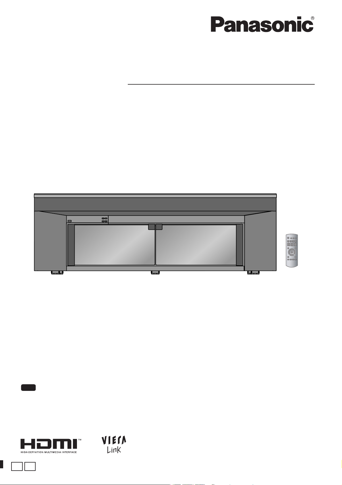
Operating Instructions
Home Theater Audio System
Model No. SC-HTR310
SC-HTR210
The illustration shows SC-HTR310.
Dear customer
Thank you for purchasing this product.
For optimum performance and safety, please read these instructions carefully.
Before connecting, operating or adjusting this product, please read the instructions completely.
Please keep this manual for future reference.
Note
“EB” on the packaging indicates the United Kingdom.
EB E
RQTX0151-B
Setting up your Home Theater system
In this manual, illustrations of SC-HTR310 are used to represent this system unless otherwise mentioned.
Before use
Step
Installing the rack
(® pages 10 to 15)
1
After you have installed the rack, attach the
glass top panel, shelf and glass doors.
Step
Setting up your Home Theater system
2
Connecting the television and DVD player
(® page 16)
(Peripheral equipment and cables are not included unless otherwise mentioned.)
Recommended TV size:
SC-HTR310
SC-HTR210
: 50 inches or less
: 42 inches or less
Basic connection
Connect with an HDMI cable for high-quality audio and video.
This connection requires HDMI terminals on both the television and
the DVD recorder. (® page 17)
Step
Enjoying movies and music
3
Enjoy surround sound with DVDs, TV, and
other sources.
This system has built-in speakers.
Do not connect other speakers with the front speakers, center
speaker and subwoofer.
If you connect other speakers, the sound will not be produced with
proper characteristics and malfunction may occur.
(® page 16)
(® pages 24 to 27)
2
RQTX0151
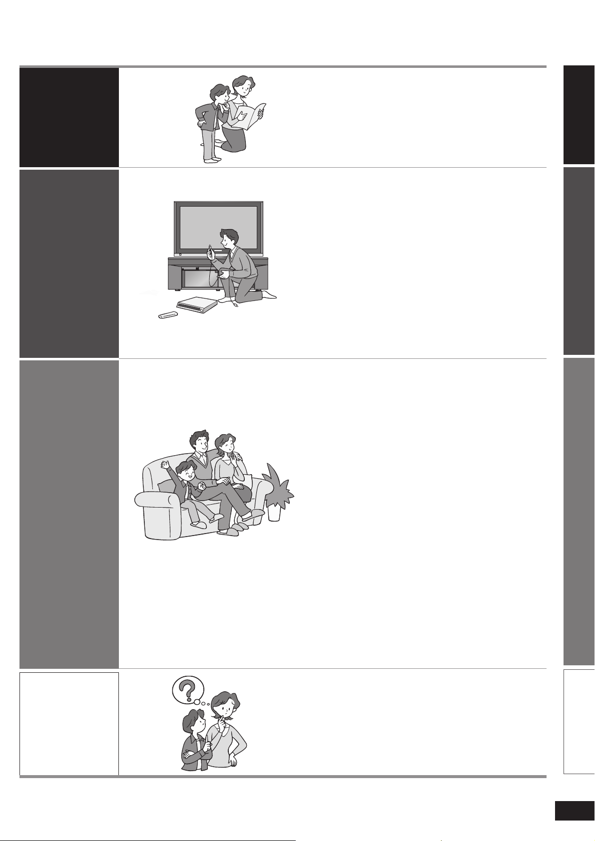
Table of contents
Before use
Connection
Setting up your Home Theater system ......... 2
Caution for AC Mains Lead ............................ 4
Safety precautions ......................................... 5
Supplied accessories ..................................... 6
Control guide .................................................. 7
Remote control preparation .......................... 9
Installing and assembling the rack ............. 10
Home Theater connections ......................... 16
Basic connections ............................................... 16
Connecting equipment with HDMI terminal (TV,
DVD recorder, etc.) ............................................. 17
Connecting with digital terminal-mounted
equipment ..........................................................18
Connecting with VCR ..........................................19
Other connections ........................................ 20
Connecting a set top box (cable or satellite) ...20
Connecting a combination DVD recorder/VCR ... 21
AC mains supply connection ...................... 22
Checking speaker output ............................. 23
Before useConnectionPlay
Play
Enjoying movies and music ........................ 24
Sound fi eld .......................................................... 26
Using the VIERA Link “HDAVI ControlTM” .. 28
Functions and settings ................................ 29
Using “WHISPER MODE SURROUND” ............. 29
Using “GAME” .................................................... 29
Muting .................................................................. 29
Adjusting speaker output .................................. 29
REAL CENTER function ..................................... 30
Adjusting sound quality .................................... 30
Adjusting the balance ........................................ 30
Reducing standby power consumption
(Standby mode) ..................................................31
Setting VIERA Link “HDAVI Control” to “OFF ”
Adjusting the time lag between audio and
video by delaying audio output ........................ 31
Switching between dual sounds ....................... 32
Clear audio at low volume ................................. 32
Switching the attenuator ................................... 32
Setting input signals .......................................... 33
Reset (factory settings) ..................................... 33
When other equipment (mini component
system, AV amp, etc.) manufactured by
Panasonic operate ............................................. 34
...
31
Reference
Error messages ............................................ 35
Specifi cations ............................................... 35
Troubleshooting guide ................................. 36
Digital signals that can be played
on this system .............................................. 37
Glossary ........................................................ 38
Maintenance .................................................. 38
Reference
3
RQTX0151
Caution for AC Mains Lead
(For United Kingdom)
(“EB” area code model only)
For your safety, please read the following text
carefully.
Before use
This appliance is supplied with a moulded three pin
mains plug for your safety and convenience.
A 5-ampere fuse is fi tted in this plug.
Should the fuse need to be replaced please ensure
that the replacement fuse has a rating of 5-ampere
and that it is approved by ASTA or BSI to BS1362.
Check for the ASTA mark or the BSI mark
on the body of the fuse.
If the plug contains a removable fuse cover you must
ensure that it is refi tted when the fuse is replaced.
If you lose the fuse cover the plug must not be used
until a replacement cover is obtained.
Caution for AC Mains Lead
A replacement fuse cover can be purchased from
your local dealer.
WARNING: DO NOT CONNECT EITHER WIRE TO
THE EARTH TERMINAL WHICH IS MARKED WITH
THE LETTER E, BY THE EARTH SYMBOL
OR
COLOURED GREEN OR GREEN/YELLOW.
THIS PLUG IS NOT WATERPROOF—KEEP DRY.
Before use
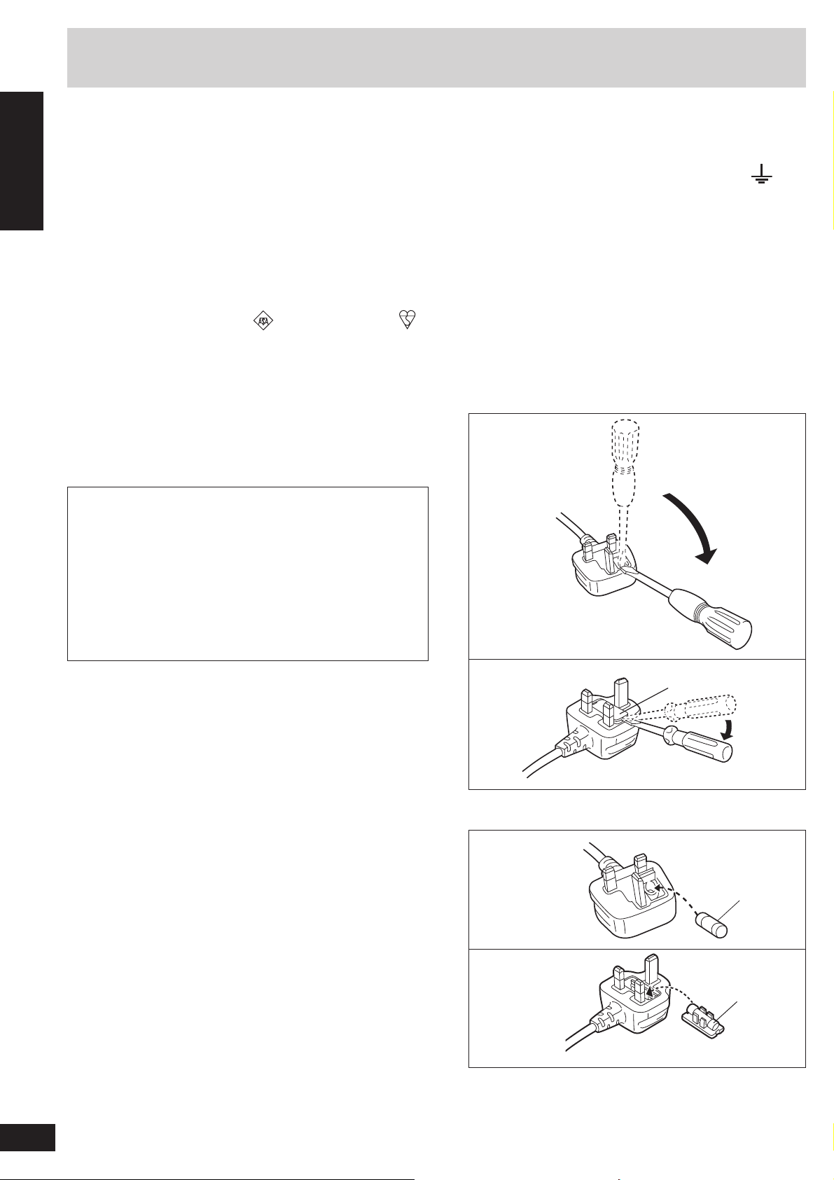
Remove the connector cover.
How to replace the fuse
The location of the fuse differ according to the type
of AC mains plug (fi gures A and B). Confi rm the AC
mains plug fi tted and follow the instructions below.
Illustrations may differ from actual AC mains plug.
1. Open the fuse cover with a screwdriver.
Figure A
CAUTION!
IF THE FITTED MOULDED PLUG IS UNSUITABLE
FOR THE SOCKET OUTLET IN YOUR HOME
THEN THE FUSE SHOULD BE REMOVED
AND THE PLUG CUT OFF AND DISPOSED OF
SAFELY.
THERE IS A DANGER OF SEVERE ELECTRICAL
SHOCK IF THE CUT OFF PLUG IS INSERTED
INTO ANY 13-AMPERE SOCKET.
If a new plug is to be fi tted please observe the wiring
code as stated below.
If in any doubt please consult a qualifi ed electrician.
IMPORTANT
The wires in this mains lead are coloured in
accordance with the following code:
Blue: Neutral, Brown: Live.
As these colours may not correspond with the
coloured markings identifying the terminals in your
plug, proceed as follows:
The wire which is coloured Blue must be connected
to the terminal which is marked with the letter N or
coloured Black or Blue.
The wire which is coloured Brown must be connected
to the terminal which is marked with the letter L or
coloured Brown or Red.
Figure B
2. Replace the fuse and close or attach the fuse cover.
Figure A
Figure B
Fuse cover
Fuse
(5 ampere)
Fuse
(5 ampere)
4
RQTX0151

Safety precautions
Placement
Set the system up on an even surface away from
direct sunlight, high temperatures, high humidity,
and excessive vibration. These conditions can
damage the system and other components, thereby
shortening the system’s service life.
Do not hang from or climb on the system. This may
result in serious injury.
Place the television properly on the system. Use the
Fall-prevention band to prevent the television from
falling over and causing serious damage or injury.
Do not place items heavier than the recommended
weight on the system or the shelves.
Voltage
Do not use high voltage power sources. This can
overload the system and cause a fi re.
Do not use a DC power source. Check the source
carefully when setting the system up on a ship or
other place where DC is used.
AC mains lead protection
Ensure the AC mains lead is connected correctly and
not damaged. Poor connection and lead damage
can cause fi re or electric shock. Do not pull, bend, or
place the system on the lead.
Grasp the plug fi rmly when unplugging the lead.
Do not move the system if AC mains lead is still
connected to socket outlet. Pulling the AC mains lead
can cause electric shock.
Do not handle the plug with wet hands. This can
cause electric shock.
Remove AC mains plug from socket outlet when not
using for a long period.
Foreign matter
Do not let metal objects fall inside the system. This
can cause electric shock or malfunction.
Do not let liquids get into the system. This can
cause electric shock or malfunction. If this occurs,
immediately disconnect the system from the power
supply and contact your dealer.
Do not spray insecticides onto or into the system.
They contain fl ammable gases which can ignite if
sprayed into the system.
Glass doors
Protect the doors from scratching.
Take care not to get your fi ngers caught when
opening and closing the doors.
Do not touch the doors if they crack. Consult your
dealer for immediate replacement.
Service
Do not attempt to repair this system by yourself. If
sound is interrupted, indicators fail to light, smoke
appears, or any other problem that is not covered in
these instructions occurs, disconnect the AC mains
lead and contact your dealer or an authorised service
center. Electric shock or damage to the system can
occur if the system is repaired, disassembled or
reconstructed by unqualifi ed persons.
Extend operating life by disconnecting the system
from the power source if it is not to be used for a long
time.
Before use
Safety precautions
5
RQTX0151

Supplied accessories
Please check and identify the supplied accessories.
Use numbers when asking for replacement parts.
(Product numbers correct as of March 2008. These may be subject to change.)
Before use
Supplied accessories
1 Glass top panel
SC-HTR310
SC-HTR210
2 Glass doors
SC-HTR310
1 x Right (RXQX0091)
SC-HTR210
1 x Right (RXQX0092)
2 Shelves
(RKQ2G0004-K)
1 Shelf
SC-HTR210
(RKQ2G0005-K)
1 AC mains lead
For the United Kingdom
(K2CT3CA00004)
: (RXQ1618)
: (RXQ1619)
: 1 x Left (RXQ1607)
: 1 x Left (RXQ1612)
SC-HTR310
:
:
Supplied accessories for amplifi er
For continental Europe
(K2CQ2CA00007)
Supplied accessories for rack
4 Caster stoppers (TBLB3008)
Left side
Right side
8 Moulded dowels
4 Moulded dowels
(RMQ1649)
2 Batteries 1 Remote control
2 Screws
(XTW4+15AFJK)
SC-HTR310
SC-HTR210
(N2QAYB000288)
6
RQTX0151
Packing plan
SC-HTR310 SC-HTR210
Shelf
(Dotted line)
Sales and Support Information
(For the United Kingdom and Republic of Ireland)
Customer Care Centre
•
For customers within the UK: 0844 844 3852
•
For customers within the Republic of Ireland: 01 289 8333
•
Visit our website for product information
•
E-mail: customer.care@panasonic.co.uk
Glass top panel Glass top panel
Glass doors
Other
supplied
accessories
Batteries
Remote
control
Rack
Direct Sales at Panasonic UK
•
Order accessory and consumable items for your product with
ease and confi dence by phoning our Customer Care Centre
Monday-Thursday 9:00am-5:30pm, Friday 9:30am-5:30pm
(Excluding public holidays).
•
Or go on line through our Internet Accessory ordering
application at www.panasonic.co.uk.
•
Most major credit and debit cards accepted.
•
All enquiries transactions and distribution facilities are
provided directly by Panasonic UK Ltd.
•
It couldn’t be simpler!
•
Also available through our Internet is direct shopping for a
wide range of fi nished products, take a browse on our website
for further details.
Interested in purchasing an extended guarantee?
Please call 0870 240 6284 or visit our website
www.panasonic.co.uk/guarantee.
Shelf
(Dotted line)
Batteries
Glass doors
Other
supplied
accessories
Rack
Remote control
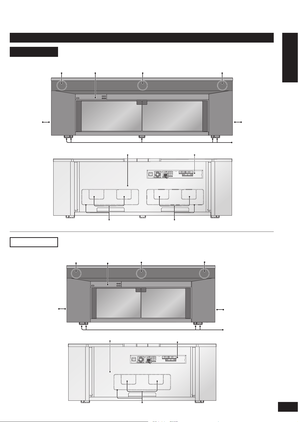
Control guide
This system
SC-HTR310
Front speaker (left)
Subwoofer
(left)
(Front view)
Control panel
(display)
(Rear view)
Center speaker Front speaker (right)
Rear panel Amplifi er
Subwoofer
(right)
Caster
Before use
Control guide
SC-HTR210
Subwoofer
(Front view)
Front speaker (left)
(left)
(Rear view)
Cut-outs Cut-outs
Control panel
(display)
Rear panel
Center speaker Front speaker (right)
Subwoofer
(right)
Caster
Amplifi er
Cut-outs
7
RQTX0151
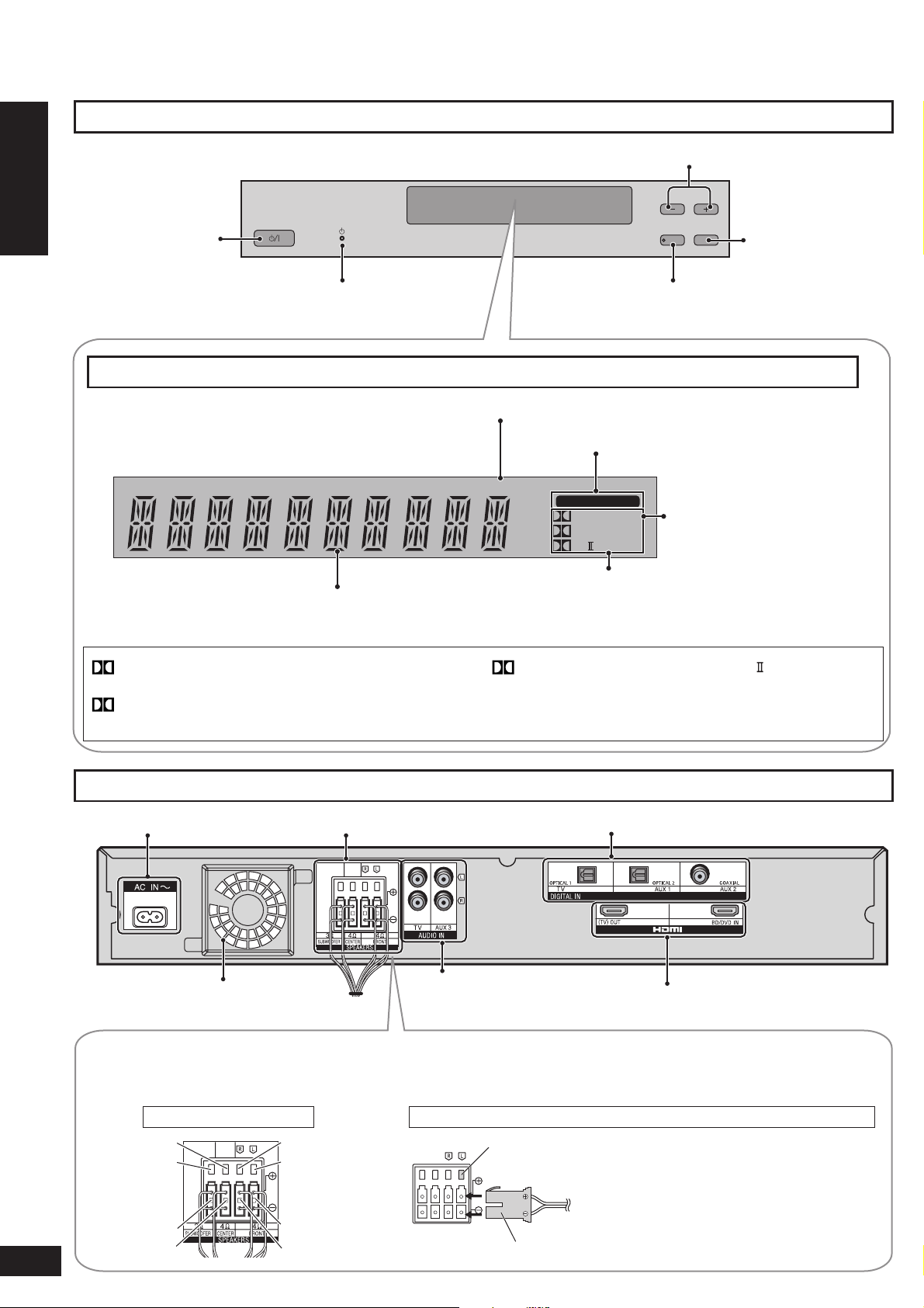
Control guide
Control panel
Before use
Standby/on switch
(® pages 22 to 24)
For adjusting volume (® page 24)
VOLUME
WHISPER MODE
INPUT
SURROUND
ゲーム(サウンド)
ゲーム(サウンド)
SELECTOR
“SELECTOR” switch
(® page 24)
Control guide
Display
DIGITAL : Dolby Digital sources
DTS : DTS sources
VS : When Dolby Virtual Speaker is working
SFC : When you are using an SFC mode
Standby indicator
(® page 22)
General display
For using “WHISPER MODE SURROUND”
(® page 29)
When input signal is fi xed to PCM (® page 33)
When input signal is digital
PCM
DIGITAL INPUT
DIGITAL DTS
VS
SFC
PL
When input signal is fi xed to
DTS (® page 33)
Digital surround signal/Sound fi eld (® below, pages 26 and 27)
PLⅡ :
(When using Dolby Virtual Speaker on
When Dolby Pro Logic decoder is being
used
2 channel stereo source)
8
RQTX0151
Amplifi er
Speaker terminalsAC inlet (® page 22) Digital input terminal (® pages 17 to 21 and 28)
Exhaust hole (Cooling fan)
Speaker terminals
The speakers are already connected. Do not touch the connectors unless absolutely necessary.
If the connectors become disconnected, refer to the illustrations below for connection.
Connector connection
Green
Purple
Purple
Green
Red
White
White
Red
Audio input terminal
(® pages 16, 17, 19 and 21)
How to attach the connectors
Terminal block
Connector
HDMI terminal (® pages 17 and 28)
Make sure the colour on the connector
indicates the same as corresponding
terminal and insert the connector straight all
the way.

Remote control
Standby/on button (® pages 23 to 25)
Test signal output (® page 23)
For using “WHISPER MODE
SURROUND” (® page 29)
For using “GAME”
(® page 29)
To enter setup mode
(® pages 29 to 34)
For selecting or cancelling
Dolby Virtual Speaker,
Dolby Pro Logic
and SFC mode
(® pages 26 and 27)
Remote control preparation
Input mode and remote control mode
buttons (® pages 24, 25 and 34)
Adjusting speaker output
(® pages 23 and 29)
For adjusting the volume
(® pages 23 to 25)
Muting (® page 29)
For adjusting settings/For activating
settings (® pages 29 to 34)
For returning to the previous menu
(® pages 29 to 34)
Before use
Control guide/Remote control preparation
Inserting the batteries
Press on the tab to open.
(R6/LR6, AA)
Insert so the poles (+ and –) match those in the
remote control.
CAUTION
Danger of explosion if battery is incorrectly replaced. Replace only with the same or equivalent type recommended by
the manufacturer. Dispose of used batteries according to the manufacturer’s instructions.
Do not use rechargeable type batteries.
•
Do not heat or expose to fl ame.
•
Do not leave the batteries in an automobile exposed to direct sunlight for a long period of time with doors and
•
windows closed.
Do not:
mix old and new batteries.
•
use different types at the same time.
•
take apart or short circuit.
•
attempt to recharge alkaline or manganese batteries.
•
use batteries if the covering has been peeled off.
•
Mishandling of batteries can cause electrolyte leakage which
can severely damage the remote control.
Remove the batteries if the remote control is not going to be
used for a long period of time. Store in a cool, dark place.
Using the remote control
Remote control signal sensor
Within 7 meters at the front
(actual distance depends on
the angle)
Transmission window
VOLUME
WHISPER MODE
SURROUND
INPUT
SELECTOR
Note
Do not place an object between the signal sensor and the
•
remote control.
Do not place the signal sensor under direct sunlight or the strong
•
light of a fl uorescent lamp.
Keep the transmission window and the system’s sensor free
•
from dust.
9
RQTX0151
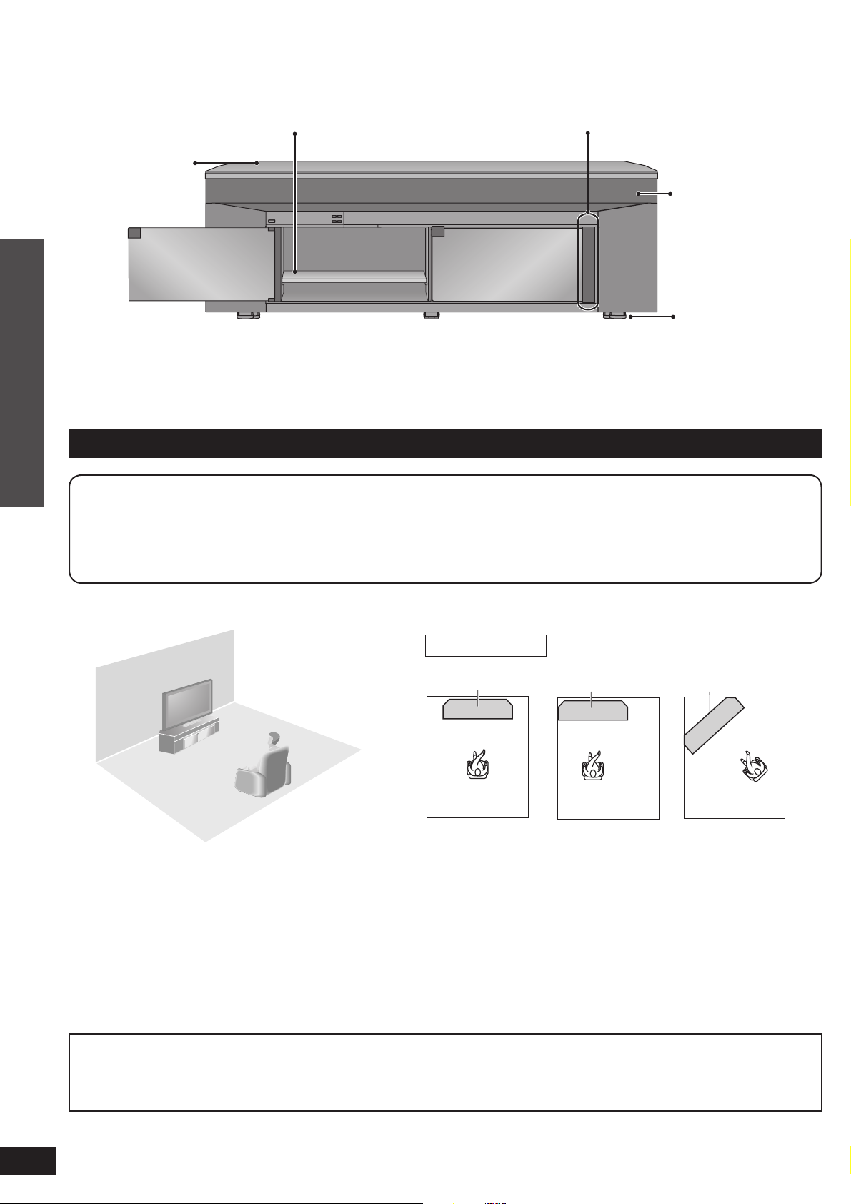
Installing and assembling the rack
Glass top
panel
assembly
(® page 12)
Installing each
equipment
Connection
Installation
At least 2 people are necessary for installation.
Use a Phillips-head screwdriver. (Do not use a powered screwdriver.)
Choose a stable location for installation.
Handle the glass top panel and glass doors with enough care.
Shelf assembly (® page 12)
Glass door assembly (® page 15)
Speaker net
Setting the caster
stoppers
(® page 14)
(DVD player/Blu-ray Disc player/DVD recorder ® page 13)
(TV ® page 13)
Installing and assembling the rack
Make sure to place the rack on a fl at, stable surface so there is no danger of it falling over. Take enough safety
•
measures to prevent the television from falling down.
You can install this system so that it is fl ush with the wall at either the sides or back, but you will require some space
•
for working during setup and connection.
Do not place in front of curtains as they may obstruct the system’s exhaust hole.
•
Avoid pressing on the speaker nets during installation.
•
If the surface of the wooden fl oor is soft, the caster mark may remain.
•
See page 11 for removing casters.
•
Caution
Use the speakers only with the recommended system. Failure to do so can damage the amplifi er and speakers, and
•
can cause fi re.
Consult a qualifi ed service person if damage occurs or if performance worsens.
•
Setup example
This system This system This system
10
RQTX0151
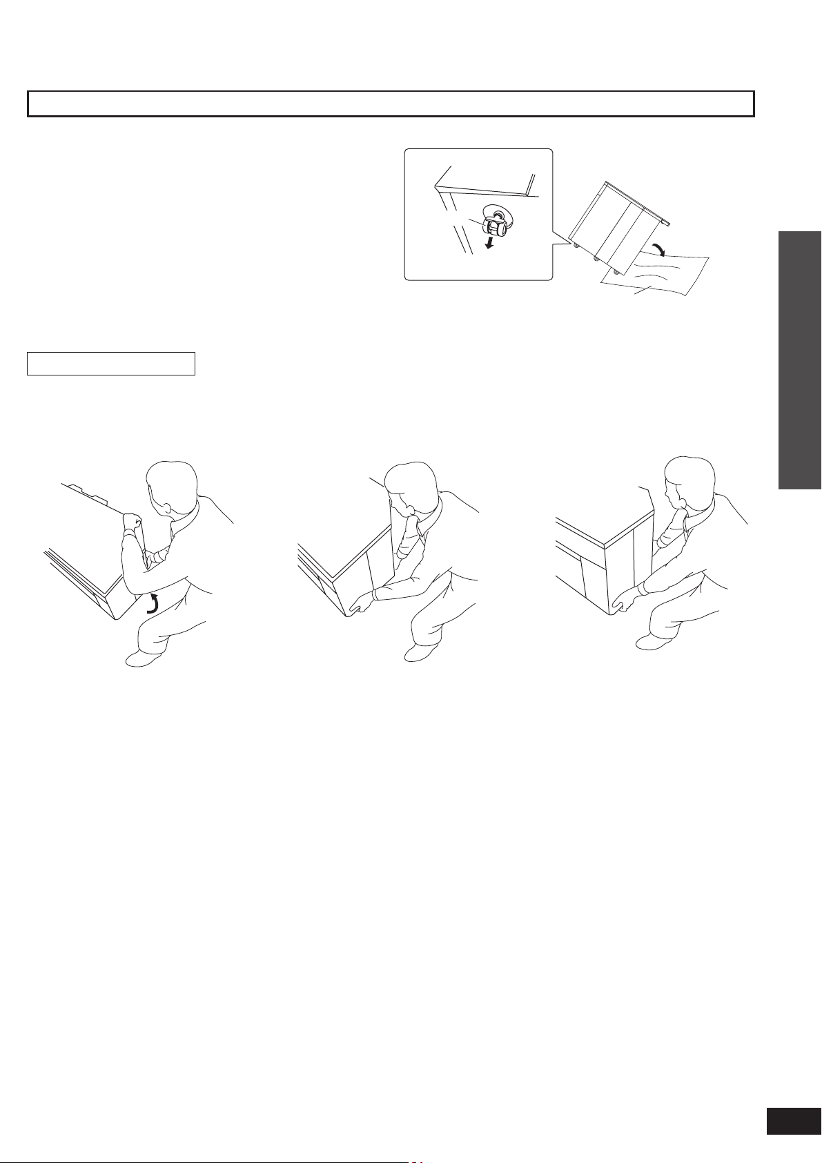
Removing casters
•
Remove casters at unstable places. (thick-piled carpet,
etc.)
•
Spread soft cloth on the fl oor and tip the rack back to
remove the casters.
•
Hold and pull to remove.
•
At least 2 people are necessary for removing casters.
•
Make sure that at least 2 people hold the bottom plate
when moving the rack after removing the casters. See the
following instructions about how to lift the rack.
•
Do not put anything on and in the rack when removing
casters. Do not put the included glass top panel either.
How to lift the rack
(Bottom plate)
Front side
Caster
Back side
Hold and pull.
Soft cloth, etc.
Lift the back side of the
1
top board and insert your
hand to the bottom of the
back side.
Back side
Front side
Insert your hand to the
2
bottom of the front side.
Lift the rack horizontally
3
using your both hands.
Connection
Installing and assembling the rack
11
RQTX0151
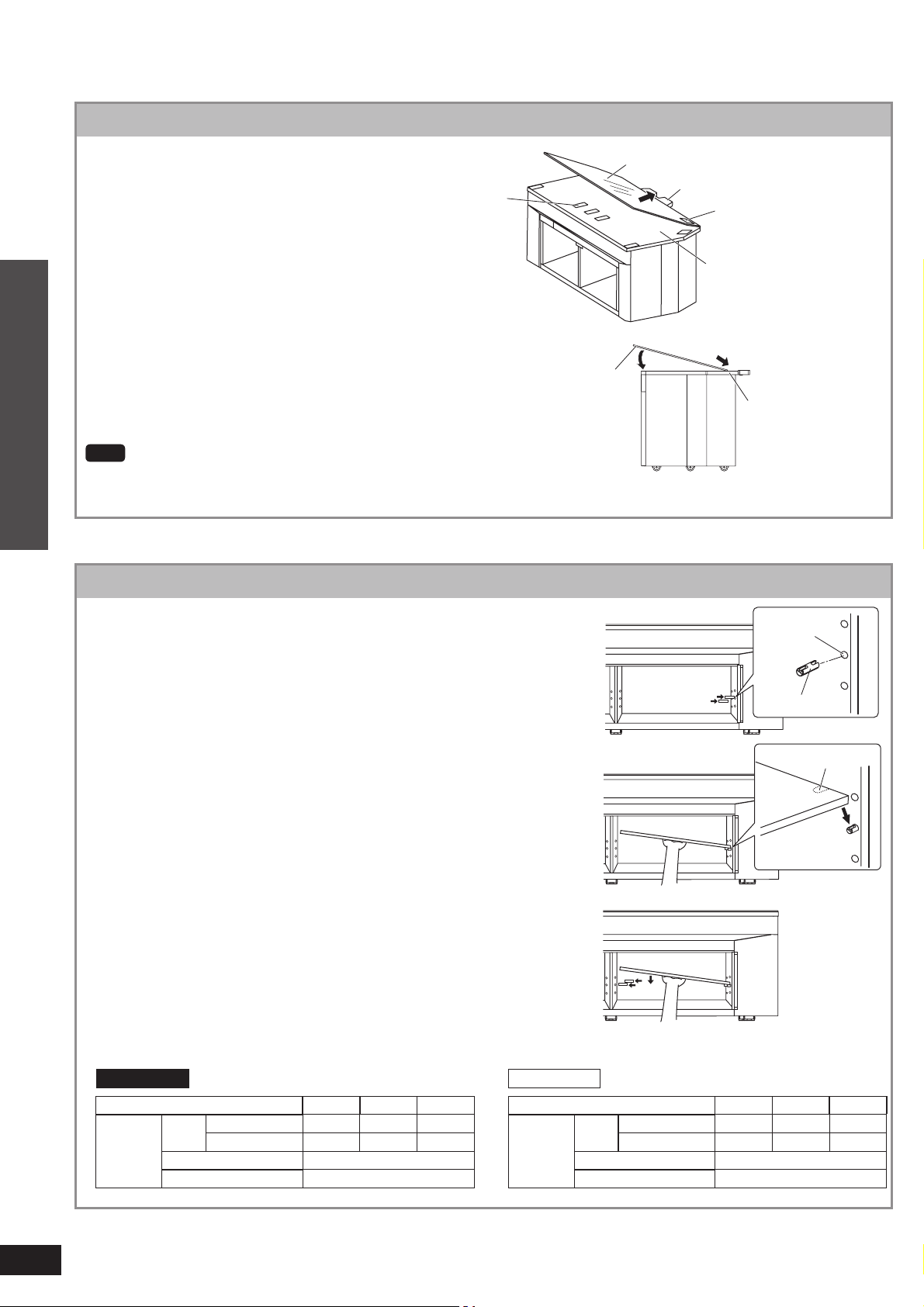
Installing and assembling the rack
Glass top panel assembly
1
2
Connection
Note
Lift up and down slowly not to make an impact on the glass.
Shelf assembly
Adjust the glass top panel (included)
to protrusion.
•
The glass top panel has the front side and back
side. Face up the front side with the sticker.
•
The nonslip sheet has been put on the top panel of
the rack. Do not remove the sheet when installing
the glass top panel.
Put it down slowly adjusting to the
top panel of the rack.
Nonslip
sheet
Glass top panel
Protrusion
Sticker
Top panel of the rack
(Side view)
Glass top panel
Top panel of the rack
Insert the moulded dowel (included) into
the dowel hole on one side.
1
Insert the shelf (included) with a slope
and set it adjusting the shelf groove to the
2
moulded dowel.
Installing and assembling the rack
Hold the shelf, insert the moulded dowel
into the dowel hole on the other side. Set
3
the shelf horizontally.
•
The height of the shelf can be adjusted at 3 different
levels.
•
Change the position of the dowels to move the shelf up or
down.
•
Insert the moulded dowel not to lose even when the shelf
is not set.
SC-HTR310 SC-HTR210
Dowel position Upper Middle Lower
Upper shelf 101 131 161
H
Compartment
Lower shelf 101 71 41
W 448 (both L and R)
D 354
UNIT: mm
Dowel position Upper Middle Lower
Compartment
Hole
Moulded dowel
Groove (Under the shelf)
Shelf
Upper shelf 98 128 158
H
Lower shelf 101 71 41
W 700
D 354
UNIT: mm
12
RQTX0151
 Loading...