

Panasonic SC-H M900 Diagram
r
r-
ROZMO121
Service Manual
Stereo system
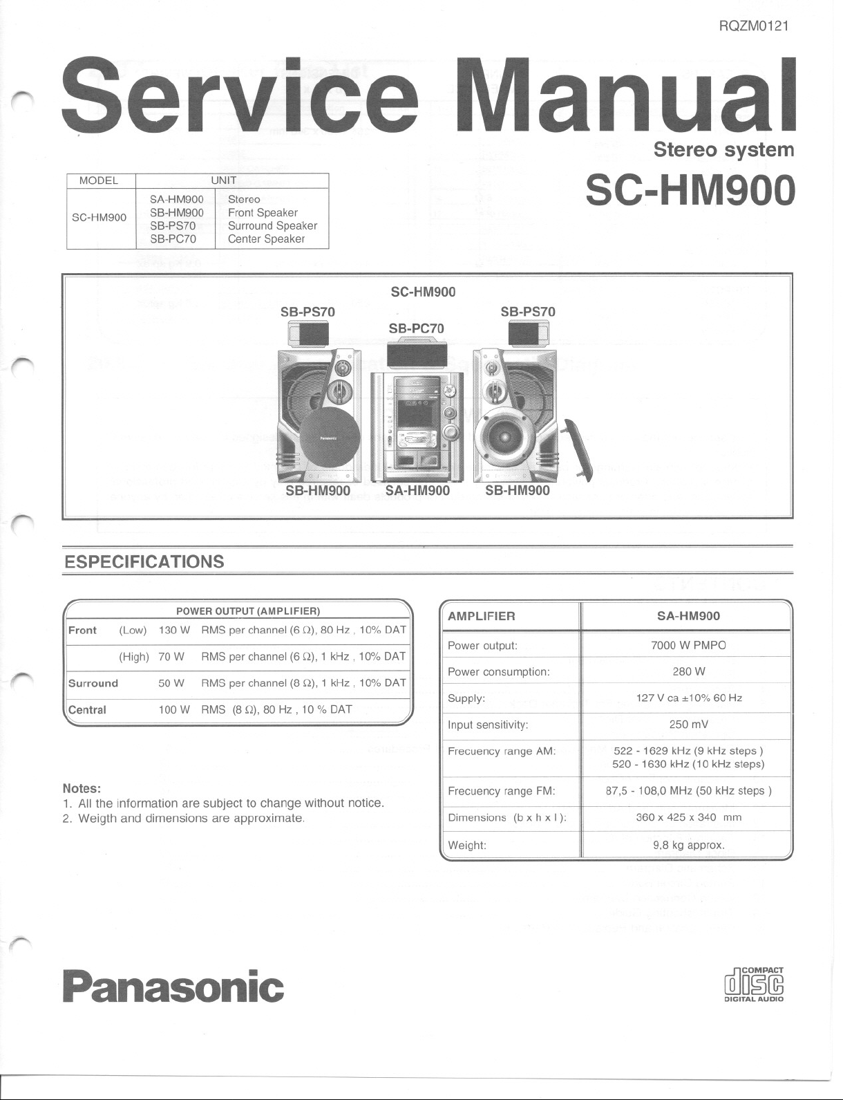
MODEL UNIT
Stereo
Front Speaker
Surround Speaker
Cantar Speaker
SB-PS70
SC-H M900
SC-HM900
SC-HM900
SA-HM900
SB-HM900
SB-PS70
SB-PC70
r-
r'-
SB-HM900
ESPECIFICA TIONS
POWEROUTPUT(AMPLlFIER)
Front
Surround
Central 100W
Notes:
1. AIIthe informationaresubjecttochangewithoutnotice.
2. Weigthanddimensionsareapproximate.
130W
(Low)
(High) 70 W
50W
RMS par ehannel(6Q), 80 Hz , 10% DAT
RMS par ehannel (6Q), 1 kHz , 10% DAT
RMS par ehannel (8 Q), 1 kHz, 10% DAT
RMS (8 Q), 80 Hz, 10% DAT
SA-HM900
SB-HM900
AMPlIFIER
Power output:
Power eonsumption:
Supply:
Input sensitivity:
Freeueney ranga AM:
Freeueney ranga FM:
Dimensions (b x h xl):
Weight:
,
SA-HM900
7000 W PMPO
280 W
127V ea:t10% 60 Hz
250 mV
522 - 1629 kHz (9 kHz steps )
520 -1630 kHz (10kHz steps)
87,5 - 108,0 MHz (50 kHz steps )
360 x 425 x 340 mm
9,8 kg approx.
,......
Panasonic
(illol!@
DIGITAL AUDIO
SC-HM900 I
P SPEAKERS
SB-HM900
FRONT
Super Tweeter
Tweeter
Woofer
Super Woofer
(high)
(Iow)
SB-PS70
SURROUND
FuI!Range
SB-PC70
CENTER 812
Tweeter
Woofer
3cm
6cm
17 cm
30 cm
8 cm 812
6cm
10 cm
INPUT DIMENSIONS
IMPEDANCE
- - -
(b x h x 1)
355 x 560 x 340 mm
- --
- --
- --
612
612
170 x 106 x 118 mm
250x121 x147mm
WEIGHT
- --
---
-- - - - -
- - - -- -
- - - -- -
- - -
9,2 Kg aprox.
-- -
- - -
-- -
0,9 Kg aprox.
1,6 Kg aprox.
Lh WARNING
This service information is designed for experienced repair technicians only and is not designed for useby the general
publico
It does not contain warnings or cautions to advise non-technical individuals of potential dangers in attempting to
service a product. Producís powered by electricity should be serviced or repaired only by experienced professional
technicians. Any attempt to service or repair the porduct or producís dealt with in this service information by anyone
else could result in serious injury or death.
~
'"
A
"""'"
~
CONTENTS
1
Safety Precaution 3
2
Before Repair and Adjustment 4
3
Protection Circuitry 4
4
Accessories 4
5
Handling Precautions For Traverse Deck 5
6
Precaution of Laser Diode
7
Operation Procedures
8
Operation Checks and Main Component Replacement Procedures 9
9
Self-Diagnostic Function """""' 17
10
Descriptionof ErrorCede"""""""" 18
11
Cd Test Mode Function """"""""""" 19
12
Measurements and Adjustments
13
lIIustration of IC, Transistors and Diodes : 23
14
Terminal Function of IC 24
15
Block Diagram
16
Schematic Diagram 35
17
Printed Circuit Board 48
18
Wiring Connection Diagram
19
TroubleshootingGuide"""""""""" 60
20
París Location and Replacement París List 61
"" 27
' 6
""""""" 7
""""""' 20
"""""""' 59
page
~
~
- 2-
-
1 SC-HM900
,.-.
,.....
1
1.
2.
3.
4-
5.
1.1
1.
2.
3.
4.
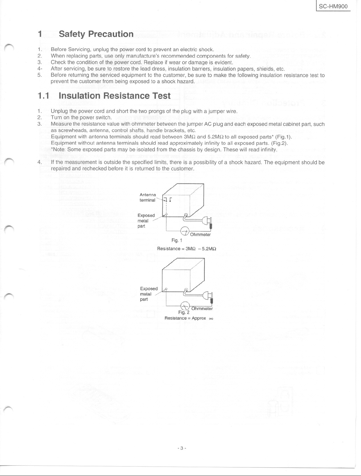
Safety Precaution
Before Servicing, unplug the power cord to prevent an electric shock.
When replacing parts, use only manufacture's recommended components for safety.
Check the condition of the power cardoReplace if wear or damage is evident.
After servicing, be sure to restorethe lead dress, insulation barriers, insulation papers, shields, etc.
Before returning the serviced equipment to the customer, be sure to make the following insulation resistance test to
prevent the customer from being exposed to a shock hazard.
Insulation Resistance Test
Unplug the power cord and short the two prongs of the plug with a jumper wire.
Turn on the powerswitch.
Measure the resistancevalue with ohmmeter betweenthe jumper AC plugandeachexposedmetalcabinetpart, such
as screwheads, antenna, control shafts, handle brackets, etc.
Equipment with antenna terminals should read between 3MQ and 5.2MQ to all exposed parts* (Fig.1).
Equipment without antenna terminals should read approximately infinity to all exposed parts. (Fig.2).
*Note: Some exposed parts may be isolated from the chassis by designoThese will read infinity.
If the measurement is outside the specified limits, there is a possibility of a shock hazard. The equipment should be
repaired and rechecked before it is returned to the customer.
,......
,......
Exposed
metal,./'/
par!
Exposed
metal/'
par!
Fig.1
Resistance ==3MO - 5.2MO
Fig-:2
Resistance==Approx 00
r---
- 3-
SC-HM900 J
2
Disconnect AC power, discharge Power Supply Capacitors POWER PCB C556, C557, C558, C559, C561 and TRANS-
FORMER PCB C705 through a 10 Q, 5W resistor to ground.
DO NOT SHORT-CIRCUIT DIRECTLy (with a screwdriver blade, for instance), as this way destroy salid state devices.
After repairs are completed, restore power gradually using a variac, to avoid overcurrent.
Current consumption at AC 127V, 60Hz in NO SIGNAL mode should be ~800mA.
3
The protection circuitry may have operated if either of the following conditions are noticed.
.
.
The function of this circuitry is to prevent circuitry damage if, for example, the positive and negative speaker connection
wires are "shorted", or if speaker systems with an impedance less than the indicated rated impedance of the amplifier are
used.
If this occurs, follow the procedure outlines below:
1.
2.
3.
Note:
Whentheprotectioncircuitryfunctions,theunitwillnotoperateunlessthepowerisfirstturnedoffandthenonagain.
Before Repair and Adjustment
Protection Circuitry
No sound is heard when the power is turned on.
Sound stops during a performance.
Turn off the power.
Determine the cause of the problem and correGíit.
Turn on the power once again after one minute.
'"'
~
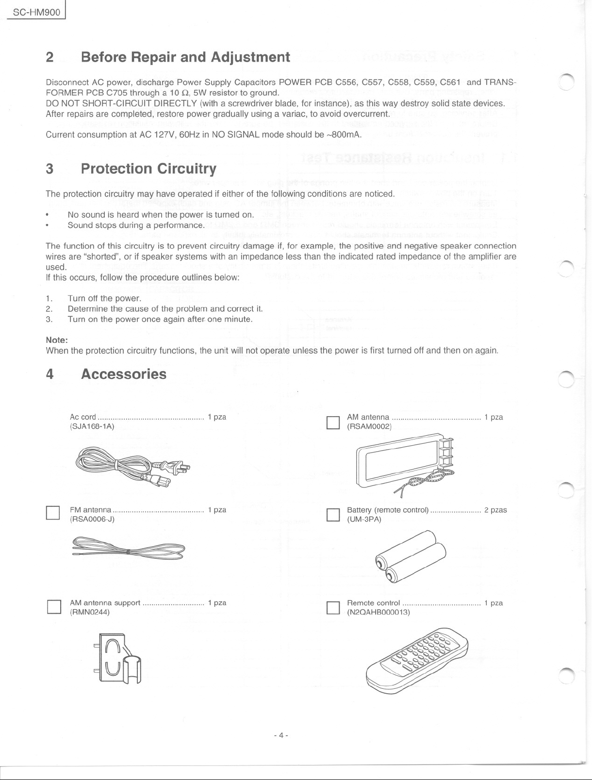
4 Accessories
Ac cord 1 pza
(SJA168-1A) D tR~~~~~~~)""""""""""""""""""""" 1 pza
Battery(remote control) 2 pzas
D f~s~~~~~-~)""""""""""""""""""""" 1 pza
D
(UM-3PA)
e
D tRMM~~~~~~support 1 pza D ~~2~ol~~~~~~113)""""""""""""""""" 1 pza
'""
~
-4-
,..-".
..
[SC-HM900
f'"
f"
5
The laser diode in the traverse deck (optical pickup) may break down due to potential difference caused by staticelectricity
of clothes or human body.
So. be careful of electrostatic breakdown during repairof the traverse deck (optical pick up).
Handling of traverse deck (optical pick up)
1. Donot subject the traverse deck (optical pickup) to static electricity as it is extremely sensitive to electrical shock.
2. Theshort land betweenthe No. 4 (LO)and No. 5 (GND) pins onthe flexible board (FFC) is shorted with a solde build-
3. Take Gafenot to apply excessive stress to the flexible board (FFC).
4. Do not turn the variable resistor (laser power adjustment). It has already been adjusted.
Handling Precautions For Traverse Deck
up to prevent damage to the laserdiode. To connect to the PC board be sure to open by removingthe solder build-up
and finish the work quickly.
Flexible board.
FFC
(Handle it carefully)
Lens
(Donottouch)
/
I
\
-
,
r
~
/
/
No.@Pin(GND) No.@)Pin(LO)
Grounding for electrostatic breakdown prevention
1.
Human body groundling
Use the anti-satatic wrist strap to discharge the static electricity from your body.
2.
Work table grounding
Pul a conductive material (sheet) or steel sheet on the afea where the traverse deck (optica! pickup) isplaced, and
ground the sheet.
Caution:
The static electricity of your clothes will not be grounded through the wrist strap. So, take Gafenotto leí your clothes touch
the traverse deck (optical pickup).
Caution when Replacing the Traverse Deck:
The traverse deck has a short point shourted with solder to proteGíthe lazer diode against electrostatics breakdown. Be
sure to remove the solder from the short point before making connections.
Variable resistor
(Do not lum)
Wriststrap
(Anti-static bracelet)
,.....
Iron plate or some metals
to conduct electricity
- 5-
SC-HM900]
6 Precaution 01 Laser Diode
CAUTION:
This unit utilizes a class 1 laser.
Invisible laser radiation is emitted from the optical pick up lens.
When the unit is turned on:
1. Donot look directly into the pick up lens.
2. Do not use optical instruments to look at tlle pick up lens.
3. Do not adjust the preset variable resistor on the pick up lens.
4. Do not disassemble the optical pick up unit.
5. If the optical pick up is replaced use the manufactures's specified replacement pick up only.
6. Use of control or adjustments or performance of procedures other than those specified here in may result in hazard-
'1"""'\
ous radiation exposure.
CAUTION!
THIS PRODUCT UTILlZES A LASER.
USE OF CONTROLS OR ADJUSTMENTS OR PERFORMANCE OF PROCEDURES OTHER THAN THOSE SPECI
FIED HERE IN MAY RESULT IN HAZARDOUS RADIATION EXPOSURE.
-"""
"""'"
" ,.
- 6-
~
...
I SC-HM900
..........
r
-
7
m
Operation Procedures
101
a Main unit
No. Name
CD Ac supply indicator (AC IN)
(This indicalor lighls when Ihe unil is connecled lo Ihe AC power supply)
(]) Standby/on switch (6/1 POWER)
Press lo switch Ihe unil Irom on lo slandby mode or viceversa. In slandby
mode, Ihe unil is slill consuming a small amounl 01 power.
@ Playtimer/record timer button (e) PLAY/ e) REC)
@ Clock/timer button (CLOCKlTIMER)
@ Signal sensor
@ 6ch button (6 CH INPUT)
(j) Karaoke select button KARAOKE
@ Microphone volume control (MIC VOL)
@ Microphonejacks 1 y 2
@ Deck 1 open button ( ~ DECK 1 OPEN)
@ Deck 1 cassette holder
@ Disctray
@ Cd manager button (CD MANAGER)
@J Disc direct play and indicators (1 - 5)
@ Disctray open/close button (~ )
@ Super3dai button (SUPER 3D Al)
@ Super sound eq button (SUPER SOUND Ea)
@ Sound equalizerknob (SOUND Ea)
@ Sound equalizercontrol (SOUND Ea)
@ Volumecontrol (VOLUME DOWN UP)
@ Headphonesjack (PHONES)
~ Deck 2 open button ( ~ DECK 2 OPEN)
e Deck 2 cassette holder
-
.
-.
""",,, I ",,"m, ,"",,'O"
rn Consola central
~ Aux select button (AUX 1/2)
@ Tuner/band select button (TUNER BAND)
@ Tape/deck select button (DECK 1/2TAPE)
@ Cd button (CD)
@ Display
@ Reverse mode select button (REV MODE)
@ Tape edil button (TAPE EDIT)
@ Dolby pro logic button ( [][JPRO LOGIC)
@ Display selectldemostration button (-DISPLAY/-DEMO)
@ Recordingbutton ( . REC/STOP)
@ Surroundbutton (SURROUND)
@ Super woofer on/off button (S. WOOFER)
@ Basic operating button
(Funclions change according lo Ihe source)
- 7-
SC-HM900 ]
I Remote control
Numberssuch asO, lunction is exactlythe same way as the buttonson
the main unit and the number such as @, lunction only with remate
control.
No. Nombre
f) Standby/on button ( <!>)
@ Auto power-off (AUTO OFF)
@ Numeric buttons (;:::10,1-9, O)
@ Program button (PROGRAM)
@ Cancel button (CANCEL)
~ Aux selector button (AUX 1/2)
e Tuner/band select button (TUNER)
G) Eqselect button (Ea)
e 3d ai button (3D Al)
a. Dolby Pro Logic button ([][] PL)
@ Play/pause/preset channel select button (only lor cd play)
(""/11IV )
@ Test button (TEST)
@ Channel selector button (CH SELECT)
G> Volume buttons (- VOLUME +)
@ Sleep button (SLEEP)
@ Muting button (MUTING)
@ Disc button (DISC)
@ Random button (RANDOM)
@ Repeat button (REPEAT)
G Disc button (CD)
e Tape/deck selct button (TAPE)
@ Skip/search bullan ( 1+11/"-, ~/~ )
@ Play/preset channel select ( ~/¡\)
~ Stop/clear program melodies (8/CLEAR)
@ Channellevel selector buttons (-CH LEVEL +)
""'""
""'"
'"'"
"--
- 8-
,........
, ,.,
Z;
ISC-HM900
r"'-
~
8
Operation Checks and Main Component Replacement
Procedures
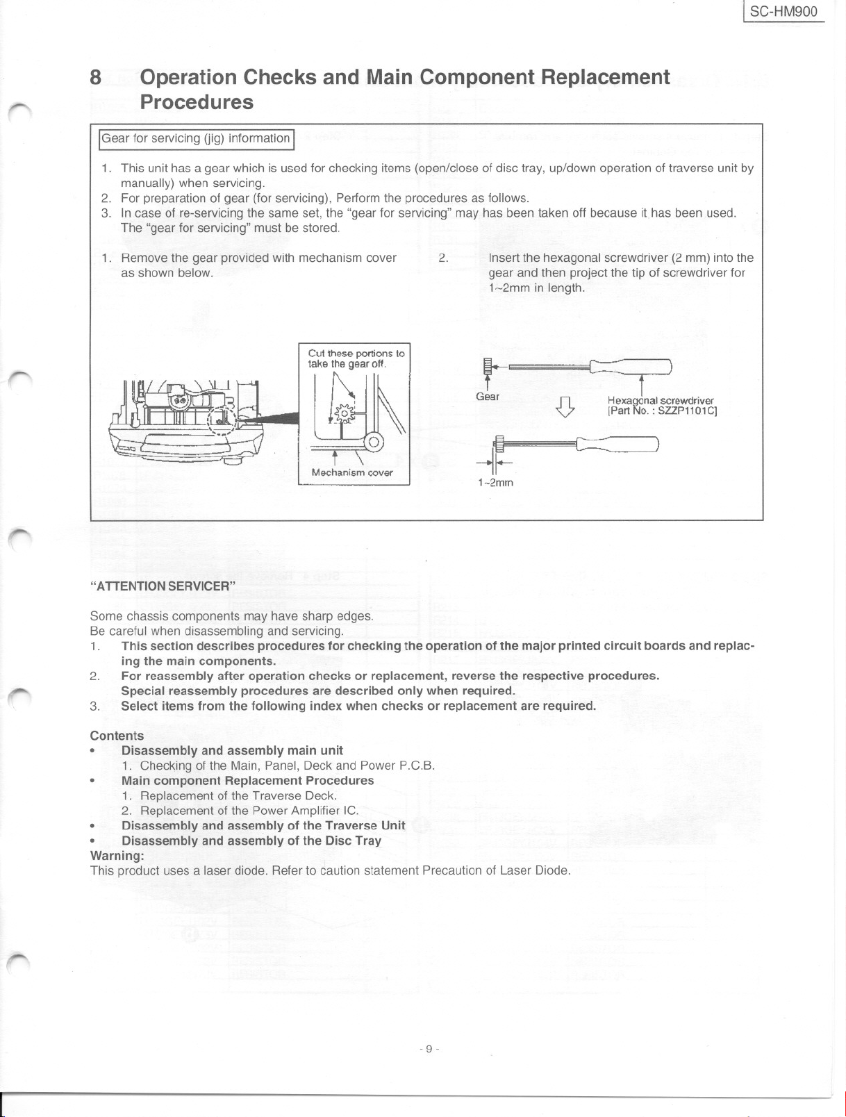
IGear for servicing (jig) informationI
1. This unít has a gear which is usedfor checking items (open/close of disc tray, up/down operation of traverse unit by
manually) when servicing.
2. For preparation of gear (for servicing), Performthe procedures as follows.
3. Incase of re-servicing the same gel, the "gear for servicing" may has been taken off because ithas been used.
The "gear for servicing" must be stored.
1. Remove the gear provided with mechanism cover
as shown below.
2.
Insertthe hexagonal screwdriver (2 mm) into the
gear and then project the tip of screwdriver for
1~2mm in length.
t-
Gear
~.
n Hexagonal screwdnver
V IPart No. : SZZP11 0.1C]
c=:
Mechanism caver
-1~
1-2mm
-
,
r
"ATTENTION SERVICER"
Some chassis components may have sharp edges.
Be careful when disassembling and servicing.
1. This section describes procedures for checking the operation of the majar printed circuit boards and replac-
ing the main components.
2.
For reassembly alter operation checks or replacement, reverse the respective procedures.
Special reassembly procedures are described only when required.
3. Select items from the following index when checks or replacement are required.
Contents
e Disassemblyandassemblymain unit
1. Checking of the Main, Panel, Deck and Power P.C.B.
e
Main component Replacement Procedures
1. Replacementof the Traverse Deck.
2. Replacement of the Power Amplifier IC.
e Disassemblyand assemblyof theTraverseUnit
e Disassemblyandassemblyof the DiscTray
Warning:
This product uses a laser diode. Refer to caution statement Precaution of Laser Diode.
,-
- 9-
SC-HM900 I
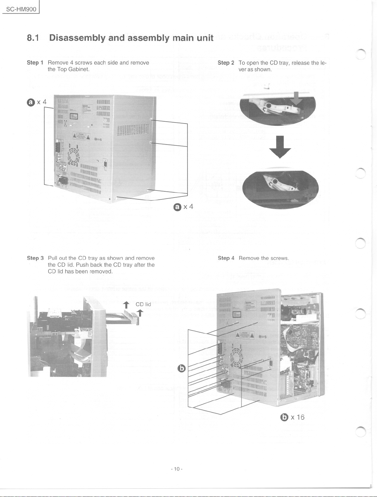
8.1
Step 1 Remove 4 screws each side and remove
E)x 4
Disassembly and assembly main unit
the Top Gabinet.
~
Step 2 To open the CD tray, releasethe le-
verasshown.
~
~
E)x 4
Step 3 Pul!out the CD tray as shown and remove
the CD lid. Push back the CD tray after the
CD lid has been removed.
~
Step 4 Remove the screws.
"'""'
G)
- 10-
0x 16
.......
~
I SC-HM900
r'
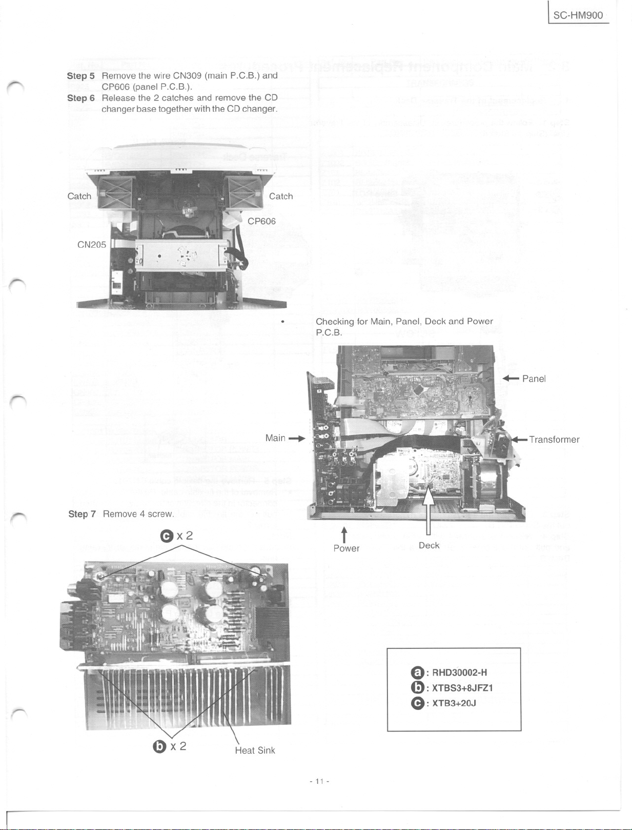
Step 5 Removethe wire CN309 (main P.C.B.) and
CP606 (panel P.C.B.).
Step 6 Releasethe 2 catches and removethe CD
changerbase togetherwiththe CDchanger.
,-
Checking tor Main, Panel, Deck and Power
P.C.B.
-.
-
,.......
Step 7 Remove4 screw.
Qx2
Main.....
Transtormer
Deck
E): RHD30002-H
4:): XTBS3+8JFZ1
ea: XTB3+20J
Heat Sink
- 11-
SC-HM900 I
8.2
1.
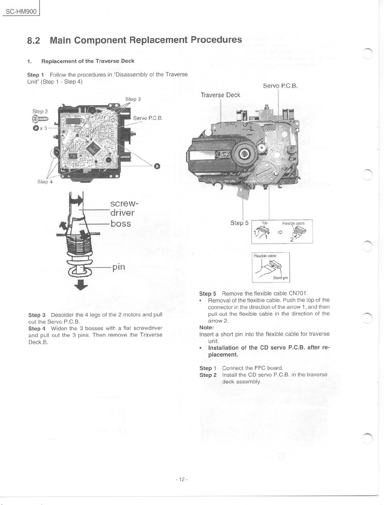
Step 1 Follow the procedures in "Disassembly of the Traverse
Unit" (Step 1 - Step 4)
Main Component Replacement Procedures
Replacement 01 the Traverse Deck
Stap3
(1
screw..
driver
Tfaverse
"""'
SeNO P.C.B.
Deck
~
"'""'-
boss
pin
~
Step 3 Desolder the 4 legs of the 2 motors and pul!
out the Servo P.C.B.
Step 4 Widen the 3 bosses with a flat screwdriver
and pull out the 3 pins. Then remove the Traverse
Deck.B.
511~
Step 5 Remove the flexible cable CN701 .
e>
. Removal of the flexible cable. Pushthe top of the
connector inthedirection of the arrow 1,and then
pul! out the flexible cable in the direction of the
arrow 2.
Note:
Insert a short pin into the flexible cable for traverse
unit.
. Installation of the CD servo P.C.B. after re-
placement.
Step 1 Connect the FFC board.
Step 2 Instal!the CD servo P.C.B. in the traverse
deck assembly.
~
"'"
- 12-
~
1 SC-HM900
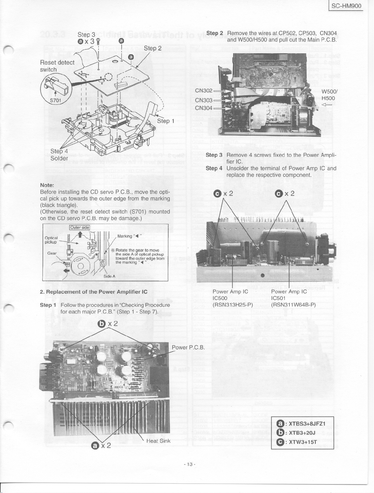
Step 2 Removethe wires at CP502, CP503, CN304
and W500/H500 and pull out the Main P.C.B.
r
..-
-
Note:
Before installing the CD servo P.C.B., move the opti-
cal pick up towards the outer edge from the marking
(black triangle).
(Otherwise, the reset detect switch (8701) mounted
on the CD servo P.C.B.may be damage.)
aptical
pickup
CN302
CN303
CN304
Step 3 Remove 4 screws fixed to the Power Ampli-
fier IC. .
Step 4 Unsolder the terminal of Power Amp IC and
replace the respective component.
ex2
ex2
W500/
H500
<J==
-
,
---
,
2. Replacement of the Power Amplifier IC
Step 1 Followthe proceduresin"CheckingProcedure
for each majar P.C.B." (8tep 1- 8tep 7).
-13-
Power Amp IC
IC500
(R8N313H25-P)
Power Amp IC
IC501
(R8N311W64B-P)
Q: XTBS3+8JFZ1
e: XTB3+20J
e: XTW3+15T
SC-HM900 I
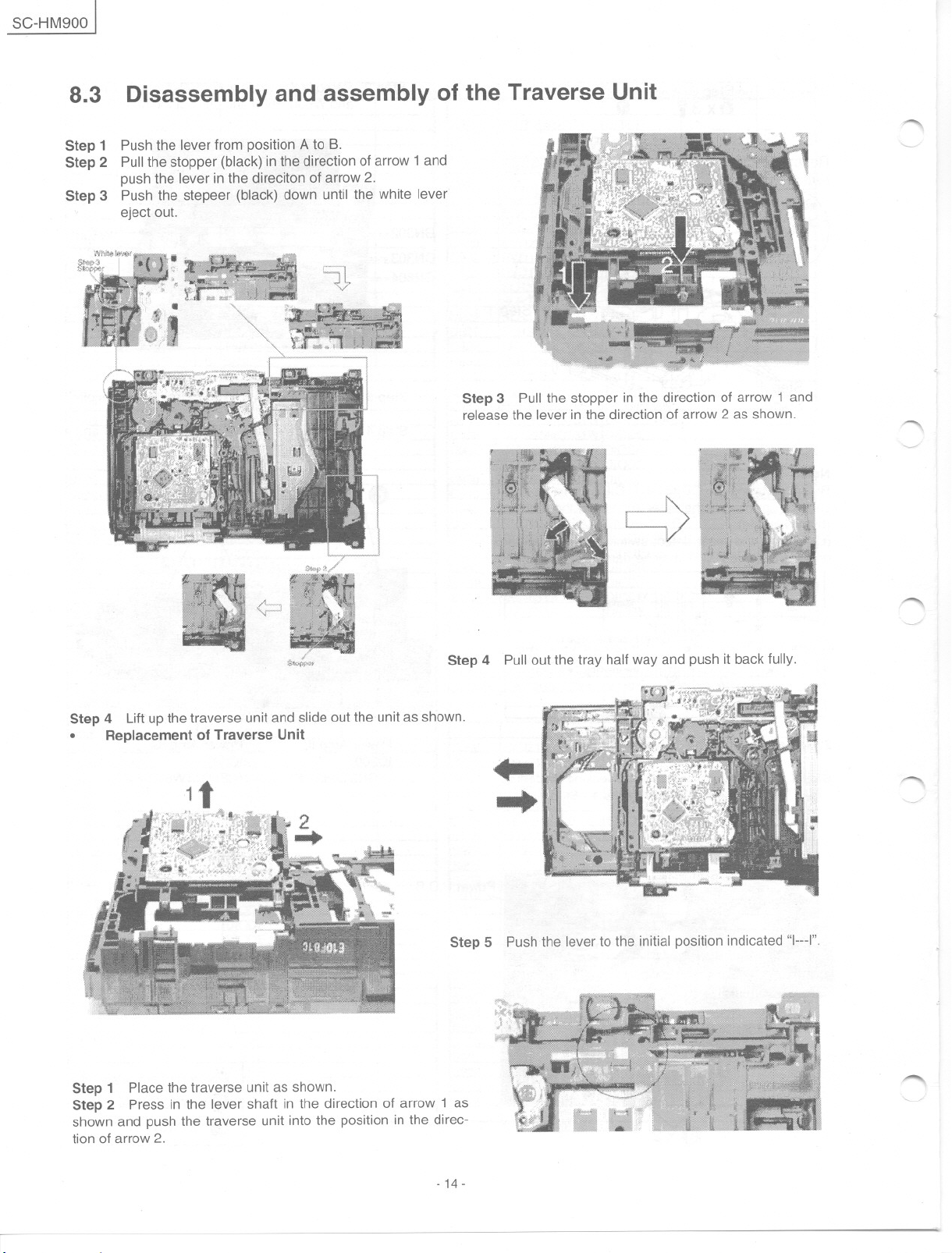
8.3
Step 1
Step 2
Step 3
Disassembly and assembly of the Traverse Unit
Push the lever from positionA to B.
Pullthe stopper (black) inthedirectionofarrow 1and
push the lever in the direciton of arrow 2.
Push the stepeer (black) down until the white lever
eject out.
Step 3 Pull the stopper in the direction of arrow 1 and
release the lever in the direction of arrow 2 as shown.
~
~
Step 4 Pull out the tray half way and push it back fully.
Step 4 Liftupthetraverse unit and slide out the unit as shown.
. Replacement 01 Traverse Unit
1t
....
....
Step 5 Push the lever to the initial position indicated "ln_I".
"""'"
'---'"
""'"
Step 1 Place the traverse unit as shown.
Step 2 Press in the lever shaft in the direction of arrow 1 as
shown and push the traverse unit into the position in the direc-
tion of arrow 2.
- 14-
,-.,.
'---~
I SC-HM900
r-
-..
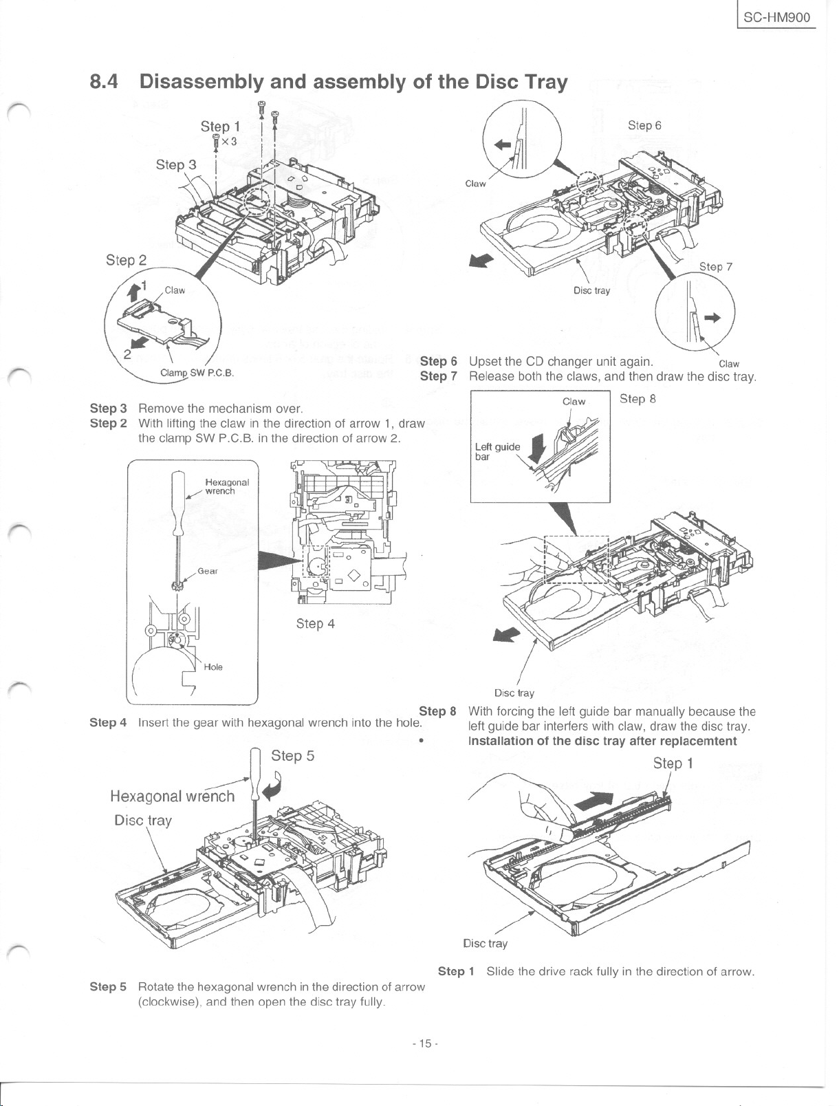
8.4
Disassembly and assembly 01 the Disc Tray
i
Step 1 If
iX3 i' ..
Step3 i
--
~
:'<;:' '
t.
'..,. ,- _.
I~i
._,"
Step 2
Clamp" SW P.C.B.
Step 3 Removethemechanismover.
Step 2 With lifting the claw in the direction of arrow 1, draw
the clamp SW P.C.B. in the direction of arrow 2.
Hexagonal
/ wreneh
<;) ,_o,"~
'~r
o Claw. ~~
~
l ~ o -~,-,
j
Step 6
Step 7
GU
O/setray
Claw
Step 6
).
..
Step 8
-.
--
Gear
Step 4
Hole
O/sefray
Step 8 With forcing the left guide bar manually beca use the
Step 4 Insert the gear with hexagonal wrench into the hojeo left guide bar interfers with claw, draw the disc tray.
. Installation of the dise tray alter replaeemtent
Step 1
~
Hexagonal wrench
Disctray
--.
Step 5 Rotatethe hexagonalwrench in the direction of arrow
(clockwise), and then open the disc tray fully.
- 15-
I
Disctray
Step 1 Slide the drive rack fully in the direction of arrow.
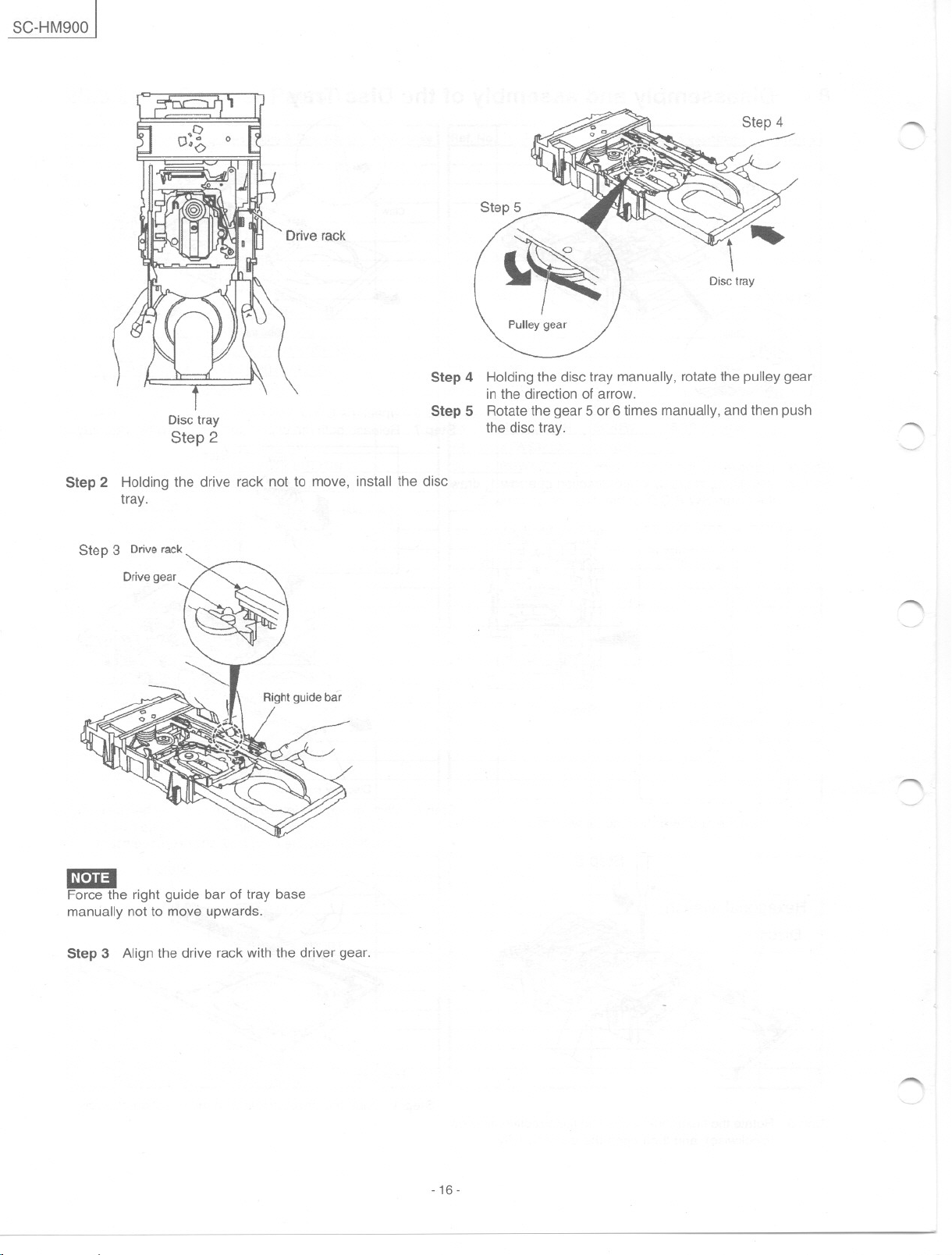
SC-HM900]
Step 4 Holdingthe disc tray manually, rotate the pulleygear
Disc tray
Step 2
Step 2 Holding the drive rack not to move, install the disc
tray.
Step 3 Driverack
Drive gear
Step 5 Rotatethe gear 5 or 6 times manually, andthen push
Step 5
in the direction of arrow.
the disc tray.
Step 4
Disctray
""'"
"
"---"
1"""""\
lmmI
Force the right guide bar of tray base
manually not to move upwards.
Step 3 Align the drive rack with the driver gear.
1"""""\
~
- 16-
1 SC-HM900
"......
--
9
9.1
This unit is equipped with a self-diagnostic display function which, if a problem occurs, will display an error code corres-
ponding to the problem.
Use this function when performing maintenance on the unit.
9.2
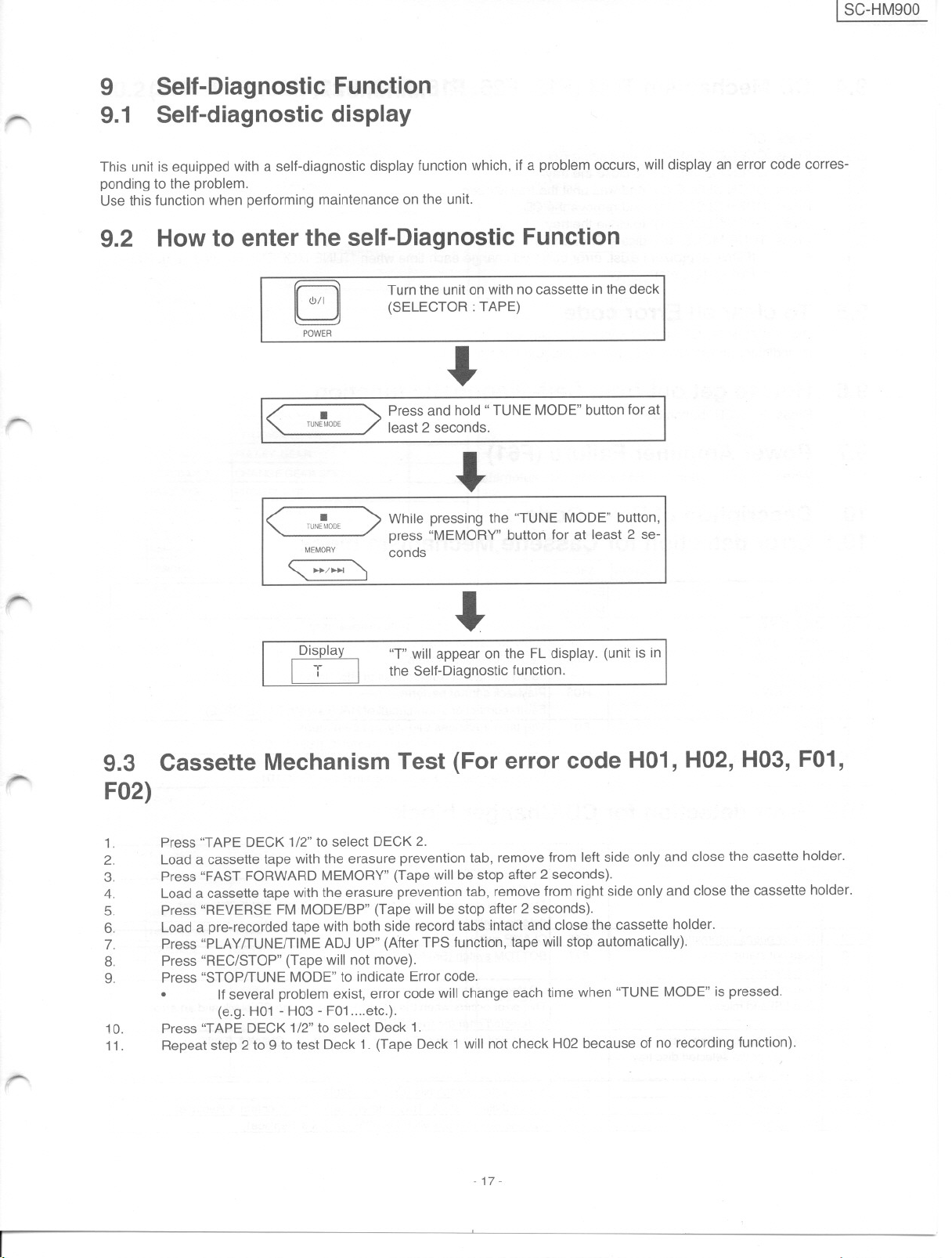
Self-Diagnostic Function
Self-diagnostic display
How to enter the self-Diagnostic Function
Turn the unit on with no cassette in the deck
G
POWER
(SELECTOR: TAPE)
.
.
TUNEMOOE
< >
Press and hold "TUNE MODE"buttonfor at
least 2 seconds.
.
.
¡UNEMOOE
<
MEMORY
"1*/»1 '1
> While pressing the "TUNE MODE" button,
press "MEMORY" button for at least 2 se-
conds
,-
r---
.
Display
I T
9.3 Cassette Mechanism Test (For error cede HO1, HO2, HO3, FO1,
FO2)
1.
2.
3.
4.
5.
6.
7.
8.
9.
10.
11.
Press "TAPE DECK 1/2"to select DECK 2.
Load a cassette tape with the erasure prevention tab, remove from left side only and clase the casette holder.
Press "FAST FORWARD MEMORY" (Tape will be stop after 2 seconds).
Load a cassettetape withthe erasure prevention tab, remove from right side only and clase the cassette holder.
Press "REVERSE FM MODE/BP" (Tape will be stop after 2 seconds).
Load a pre-recordedtape with both side recordtabs intact and clase the cassette holder.
Press "PLAY/TUNEITIMEADJ UP" (After TPS function, tape will stop automatically).
Press "REC/STOP" (Tapewill not move).
Press "STOP/TUNE MODE"to indicate Error codeo
. If several problem exist, error code will change each time when "TUNE MODE" is pressed.
(e.g. H01 - H03 - F01 etc.).
Press "TAPE DECK 1/2"to select Deck 1.
Repeat step 2 to 9 to test Deck 1. (Tape Deck 1 will not check H02 because of no recording function).
"T" will appear on the FL display. (unit is in
the Self-Diagnostic function.
---
I
- 17-
SC-HM900 J
9.4
1.
2.
3.
4.
5.
6.
7.
CD Mechanism Test (F15, F26, F16, F17, F27, F28, F29, H15)
Press "CD".
Press "OPEN/CLOSE (1)" and place a CD.
Press "OPEN/CLOSE (1)" to clase the tray.
Press "OPEN/CLOSE(5)"and wait until the tray is apeno
Press "OPEN/CLOSE (1)" and remove the CD.
Press "OPEN/CLOSE (1)" to clase the tray.
Press "TUNE MODE"to indicate Error Codeo
. It several problem exist, error cede will change each time when "TUNE MODE" is pressed. (e.g. F15 -
F26 - F16... etc).
9.5
1.
2.
9.6
1.
9.7
1.
To clear all Error cede
Press "STOP /TUNE MODE" button tor 5 seconds.
FL indicator shows "CLEAR" tor 1 second and change to "T".
How to gel out from Self-Diagnostic function
Press "POWER" button OFF.
Power Amplifier Failure (F61)
When power amplitier tail, F61 will indicate automatically.
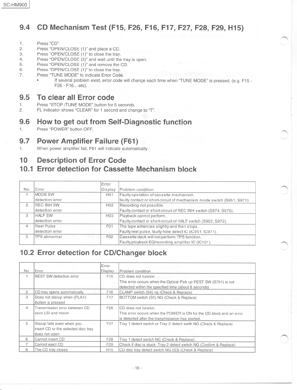
10 Description of Error Cede
10.1 Error detection for Cassette Mechanism block
~
"
Error
No. Error
1 MODESW
detection error
2
REC INH SW
detection error
3
HALF SW
detection error
4
Reel Pulse
detection error
5 TPS abnormal
Display
Problem condition
H01
Faulty operation,ol cassette mechanism
laulty contact or short-circuit 01mechanism mode switch (S951, S971).
H02
Recording not possible.
Faultycontact or short-circuit 01REC INH switch (S974, S975).
H03
Playback cannot perform.
Faulty contact or short-circuit 01HALF switch (S952, S972).
F01
The tape advances slightly and then stops.
Faulty reel pulse, laulty hole detect IC (IC951, IC971).
F02
Cassette deck will not perform TPS lunction.
Faulty playback EQ/recording amplilier IC (IC101).
10.2 Error detection for CD/Changer block
Error
No. Error
1 REST SW detection error
2 CDtrav ooens automaticallv F16
3
Does not starup when (PLAY)
Button is aressed
4
Transmission error betweenCD
sevo LSI and micon
5
Starup lails even when you
insert CD or the selected disc tray
does not caen
6
Cannot insert CD
7 Cannot eiect CD F29
8
The CD trav clases H15
Displav Problemcondition
F15 CDdoes not luncion
This error occurs when the Optical Pick up REST SW (S701) is not
detected within the specilied time (about 8 seconds)
CLAMP switch (S4) no (Check& Replace)
F17
BOTTOM switch (S5) NG(Check & Replace)
F26
CD does not luncion
This error occurs when the POWER is ON lor the CD block andan error
is detected alter the transmisission has started.
F27
Tray 1detect switch or Tray 2 detect swith NG (Check & Replace)
F28 Trav 1detectswitch NG (Check& Replace)
Check il disc is stuck. Trav 2 detect switch NG (Conlirm & Replace)
CD disc trav detect switch NG (S3) (Check& Replace)
1""""\
..-....
---/
~
- 18-
r
--
I SC-HM900
10.3 Power Supply related error detection
Error
Error Displav
No.
1
POWER AMP
output abnormal During normal operation, if DC DEr become L, PCNT shall become
Problem condition
F61
When POWER is switched on, power become off automatically.
L and the error display on the left shall be displaved. IIC501)
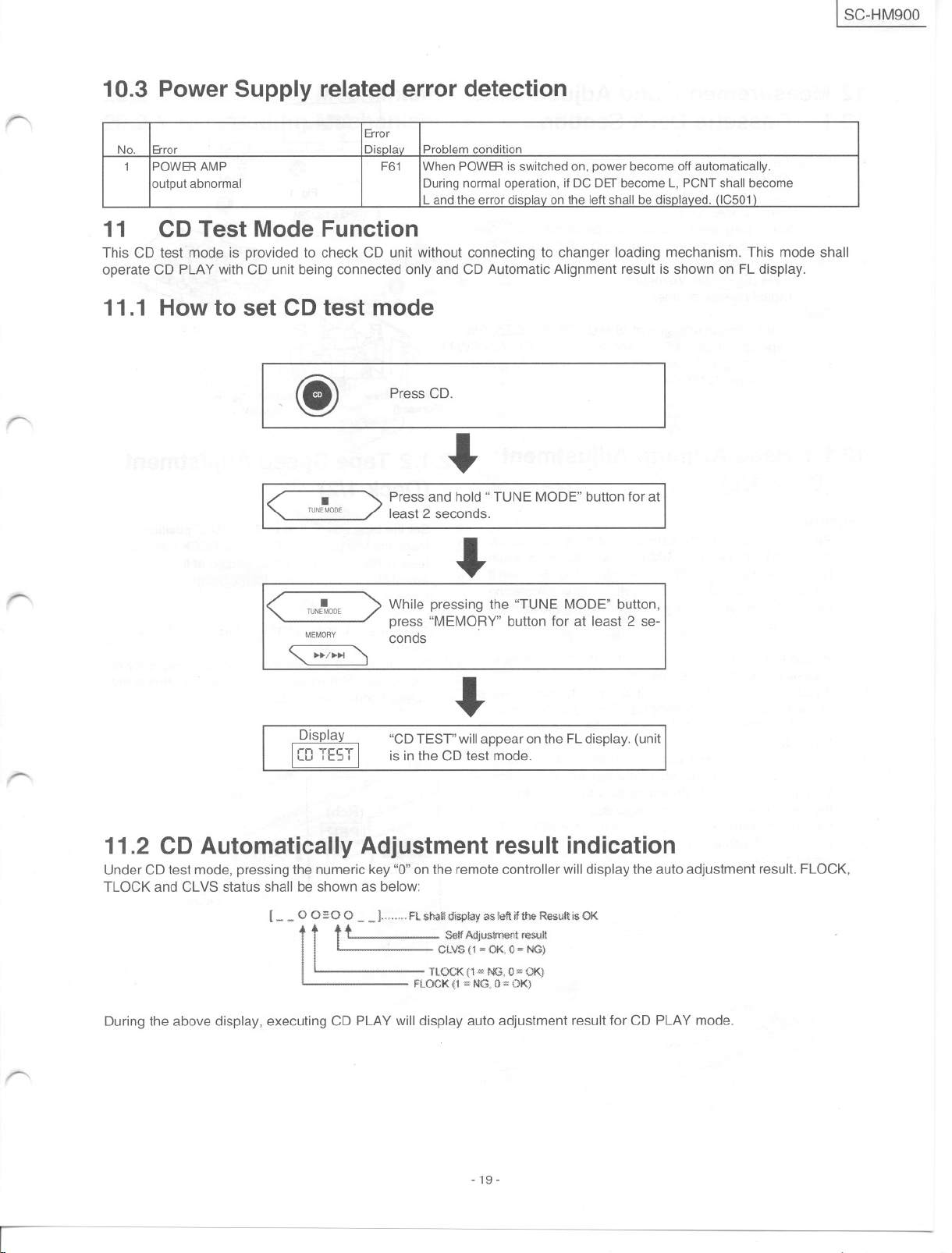
11 CD Test Mode Function
This CD test mode is provided to check CD unit without connecting to changer loading mechanism. This mode shall
operate CD PLAY with CD unit being connected only and CD Automatic Alignment result is shown on FLdisplay.
11.1 How to set CD test mode
Press CD.
(j)
.
-..
-..
Press and hold "TUNE MODE"buttonlor at
least 2 seconds.
>
<
.
TUNEMDOE
.
<
MEMORY
> While pressing the "TUNE MODE" button,
press "MEMORY" button lor at least 2 se-
conds
.
TUNEMQDE
"-1- ~
.
"CD TEST" will arrear on the FL display. (unit
is in the CD test mode.
11.2 CD Automatically Adjustment result indication
UnderCDtest mode,pressingthe numeric key"O"on the rematecontroller willdisplaytheauto adjustment result. FLOCK,
TLOCK and CLVS status shall be shown as below:
[- - O0",0 0- - ]." FLshaUdisplay as Mflifthe Result isOK
'
"
. CLV$(1'"OKú=NG}
.
t tt
."'",
~
se
lfAdJustme
.
TLQC.K(1 '" NO, O"'OKi
.
FLOCK{1 =NG,O= OK)
nt.teSl.
..
J
1I
.
..
During the above display, executing CD PLAY will display auto adjustment result lor CD PLAY mode.
-..
- 19-
r
SC-HM900 J
12 Measurements and Adjustments
CH
12.1 Cassette Deck Section
.
Measurement Condition
Reverse-mode selector switch:
Tape edit: NORMAL
Record timer: OFF
Make sure head, capstan and press rolier are clean.
Judgeable room temperature 20 :t 5°C (68 :t 9°F)
Measuring instrument
EVM (Electronic Volmeter)
.
12.1.1 Head Azimuth Adjustment
CAUTION:
. Please replace both azimuth adjustment screw
.
1.
2.
3.
Digital quency counter E.HEAD R/PHEAD
Test tape
- Head azimuth adjustment (8 kHz, -20 dB); QZZCFM /. Fig.:3
- Tape speed gain adjustment (3 kHz, -10 dB); AZZCWAT .
- Playback gain adjustment (315 Hz, OdB); AZZCFM L I
- CrO2tape,QZZCRX '
AzimuthScrew AzimuthScr8W
(Forward) (Reverso)
12.1.2 Tape Speed Adjustment
(Deck 1/2)
(rhe5152zb) and springs (RM0331) simultaneosly when
readjusting the head azimuth. (shown in Fig. 2). Even if
you wish to readjust the head azimuthwithout replacing
the screws and springs,afine adjustmentto the azimuth
screw and spring.
Please remove the screw-Iocking bond left on the head
base when replacing the azimuth screw.
If you wish to readjust the head azimuth, be sureto ad-
just withadheringthe cassettetapecloselytothe mecha-
nism by pushing the center of cassette tape with your
finger. (shown in Fig. 3)
Playbackthe azimuth adjustment portion(8kHz,-20dB)
of the test tape (QZZCFM) in the forward play mode.
Vary the azimuth adjustment screw until the output of
the R-CH (PB OUT-A) are maximized.
Perform the same adjustment in the reverse play mode.
After the adjustment, apply screwlock to the azimuth
adjusting screw.
(Deck 1/2)
1.
Set the tape edil button to "NORMAL" position.
2.
Ingeríthe test tape (QZZCWAT)to DECK2and play-
back (FWD side) the middle portion of i1.
3.
AdjustMotorVR (DECK2)forthe outputvalueshown
below.
, Adjustment target: 2940 - 3060 Hz (NORMAL
speed)
4.
After alignment, assure that the output frequency of
the DECK 1 FWDis within:t60Hzof thevalueof the
output frequency of DECK 2 FWD.
UNIT
liDI IPBRj
. (GND) L
A
(PeOUT-A) ;~
~
:",u"""':::::::uu, t@o""" u... """ - -
T (RHE5152ZB)
8 (RM80331)
Fig.2
~
Ag. 4
(Rch)
,'u o
Fig.1
~ ~-'-
-u-u.. O
;
EVM
i I
~
-.. - c-
~
Digital frequency
counter
--..
"'"""
--..
--..
- 20..
, ".
[SC-HM900
---
r'
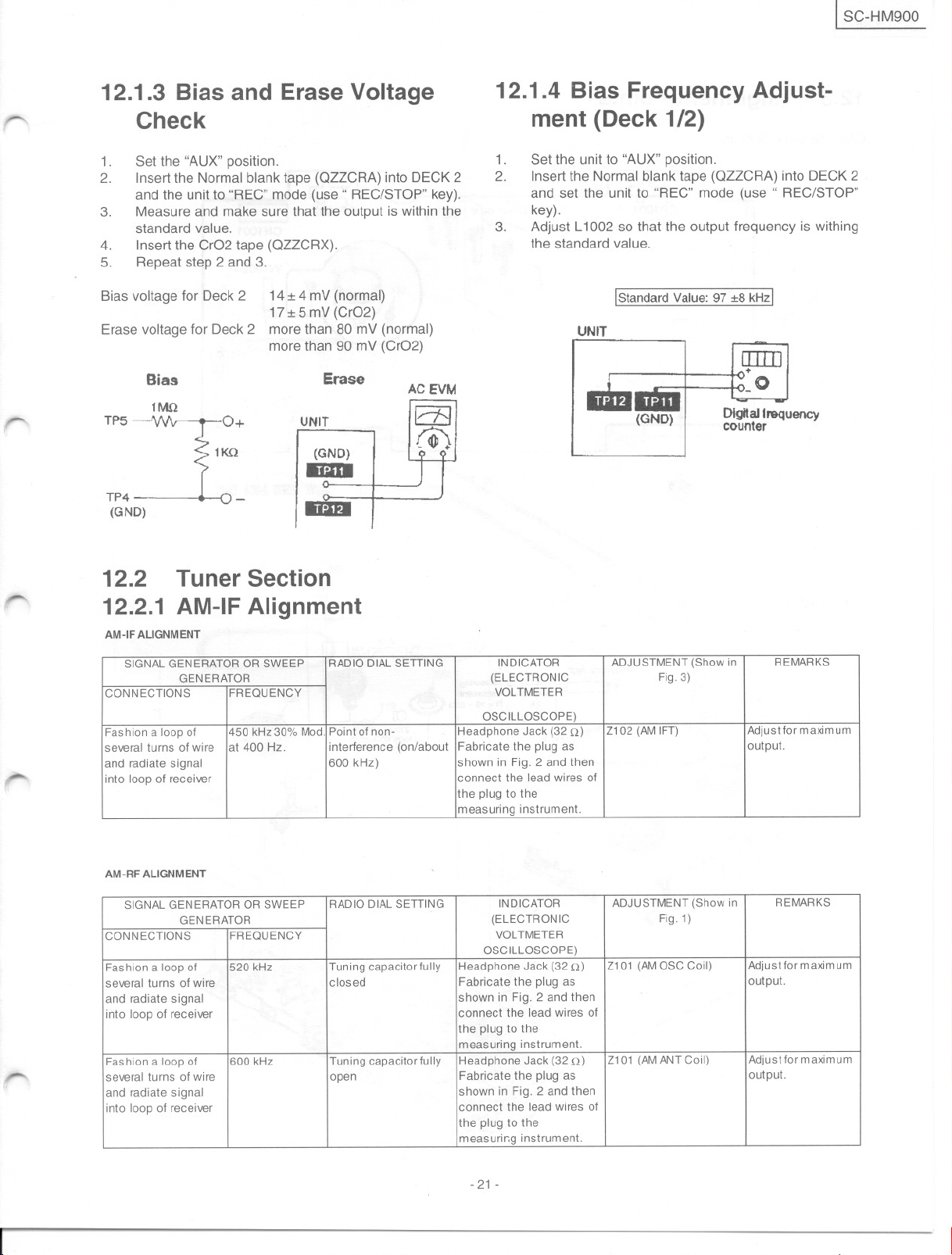
12.1.3 Bias and Erase Voltage
Check
1.
Set the "AUX" position.
2.
Insertthe Normal blank tape (OllCRA) into DECK2
and the unit to "REC" mode (use" REC/STOP" key).
3.
Measure and make sure that the output is within the
standard value.
4.
Insert the CrO2 tape (OllCRX).
5.
Repeat step 2 and 3.
Bias voltage tor Deck 2 14 :t 4 mV (normal)
17:t 5 mV (CrO2)
Erase voltage tor Deck 2 more than 80 mV (normal)
more than 90 mV (CrO2)
Bias
T :r.
1KQ
TP4
(GND) -
Erase
UNIT
r=l
BDI
1118
ACEVM
rm
12.1.4 Bias Frequency Adjust-
ment (Deck 1/2)
1.
Set the unit to "AUX" position.
2.
Insert the Normal blank tape (OllCRA) into DECK 2
and set the unit to "REC" mode (use" REC/STOP"
key).
3.
Adjust L1002 so that the output trequency is withing
the standard value.
¡Standard Value: 97 :t8 kHzl
UNIT
lIIllJ
+
_O
(GND)
Dlgltaltrequency
counter
12.2 Tuner Section
r
,-
r-
12.2.1 AM-IF Alignment
AM-IF ALlGNMENT
SIGNAL GENERATOR OR SWEEP
CONNECTIONS FREQUENCY
Fashion a loop 01
several turns 01wire
and radiate signal
into loop 01 receiver
AM-RF ALlGNMENT
SIGNAL GENERATOR OR SWEEP
CONNECTIONS
Fashion a loop 01
several turns 01wire
and radiate signal
into loop 01 receiver
Fashion a loop 01
several turns 01wire
and radiate signal
into loop 01 receiver
GENERATOR
450 kHz30% Mod.
at 400 Hz.
GENERATOR
FREQUENCY
520 kHz
600 kHz
RADIO DIAL SETTING INDICATOR
Point 01non-
interference (on/about Fabricate the plug as
600 kHz) shown in Fig. 2 and then
RADIO DIAL SETTING INDICATOR
Tuning capacitar lully Headphone Jack (32 n)
closed
Tuning capacitar lully Headphone Jack (32 n)
open
(ELECTRONIC Fig. 3)
VOLTMETER
OSCILLOSCOPE)
Headphone Jack (32 n)
connect the lead wires 01
the plug to the
measuring Instrument.
(ELECTRONIC Fig. 1)
VOLTMETER
OSCILLOSCOPE)
Fabricate the plug as
shown in Fig. 2 and then
connect the lead wires 01
the plug to the
measunng instrument.
Fabricate the plug as
shown in Fig. 2 and then
connect the lead wires 01
the plug to the
measurir.g Instrument.
ADJUSTMENT(Showin
Z102 (AM 1FT) Adjustlor maximum
ADJUSTMENT (Show in
Z101 (AMOSC Coil) Adjustlormaximum
Z101 (AMANTCoil)
REMARKS
output.
REMARKS
output.
Adjustlormaximum
output.
-21-
SC-HM900 I
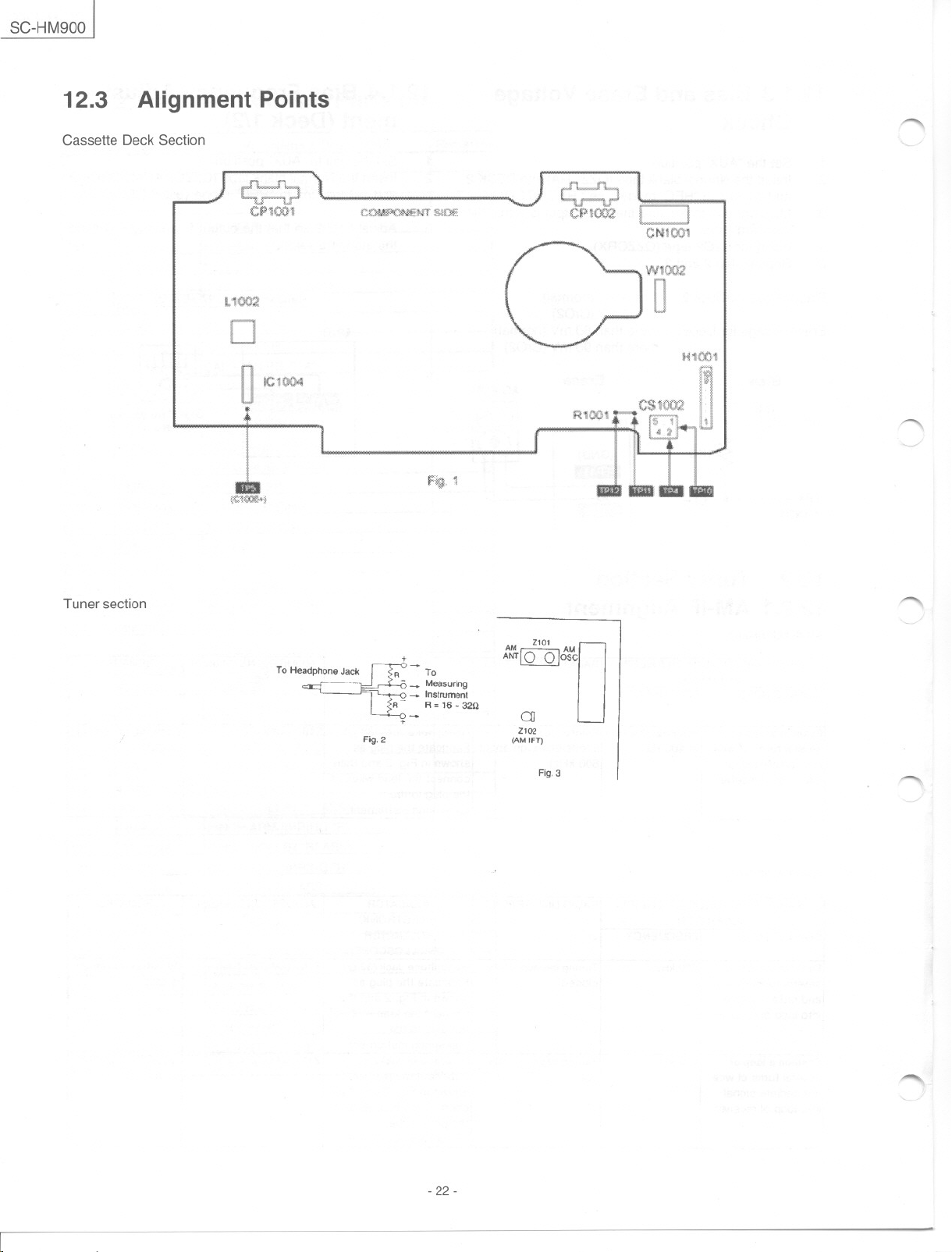
12.3
Cassette Deck Section
Alignment Points
1.1002
o le! lJO4
"
..
I
.
\C1@:1?;j
~
e~m
(:1'41(.*)1
H1oo1
~
Tuner section
R -To
--Measuring
. ~ -Instruman!
~R- R=16 -32G
+-o -
+
Fig.2
2101
AM AM
~: O~,
2102
(AMIFT)
Fig.3
"'"""
O
, ,....
- 22-
..........
-
ISC-HM900
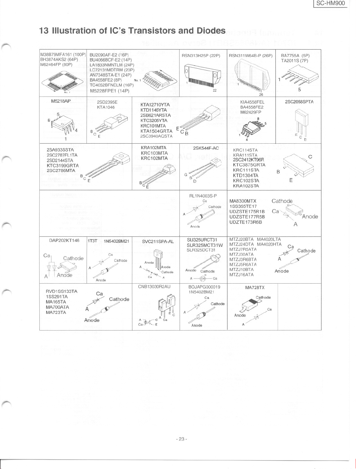
13 lIIustration of IC's Transistors and Diodes
-
-
M38B79MFA161 (100P)
BH3874AKS2 (64P)
M62464FP (80P)
N,.1
M5218AP
8,
1
2SC2787FL 1TA
I
2SD2144STA
KTC3199GRTA
2SC2786MTA
BU2090AF-E2 (16P)
BU4066BCF-E2 (14P)
LA 1833NMNTLM (24P)
LC72131MDTRM (20P)
AN7348STA-E1 (24P)
BA4558FE2 (8P)
TC4052BFNELM (16P)
M5228FPE1 (14P)
2SD2395E
KTA1046
t>lo.1
KTA12710YTA
2SB621ARSTA .)
KTD11<6YTA"
KTC3205YTA"
B
CE 2SC3940AOSTA
KRC101MTA E
KTA1504GRTA e B
KRA102MTA
KRC103MTA
KRC102MTA
RSN313H25P (22P) IRSN311W64B-P (26P) BA7755A (5P)
/:">-~
""
TA2
011S(7P)
.
~ (::::11 1~
~ 1 ~) ~./~~
2SK544F-AC
-P/#
G /./
s /.
D
RL 1N4003S-P
22 // 5
::::9>
4.
Ca
7/- Cathode
A'&
~?'-~
Anode
l
"'..'...".".""'.".
lJ
KIA4558FEL
BA4558FE2
M62429FP
8
15
4
KRC114STA2SA933SSTA
KRA111STA
2SC2412KT96R
/; KTC3875GRTA
KRC111STA
KTD1304TA
KRC102STA
KRA102STA
MA8300MTX
1SS355TE 17
UDZSTE175R1
UDZSTE177R5B
UDZTE173R6B
26
Cathode
B
2SC2058SPTA
.~ El
//-"'-<--- C
~ ~"
0'~_,
'" ~- / /
~
B ¿:'-"-':::1'/
E
A
//
-.
~-
DAP202KT146
RVD1SS133TA
1SS291TA
MA165TA
MA700ATA
MA723TA
11T3T
1N5402BM21I
Ca
. // MTZJ5R6ATA
7/' Cathode AnodeI
A'.f
$Y
Anode
Ca
./
A/
Anode
:Ode
SVC211SPA-AL I
o MTZJ30ATA
A Anode
' Cathode
Ca 'A
CNB13030R2AU
A j5rC Ca
Ca -E
SLl325URCT31
SLR325MCT31W
SLR325DCT31
BOJAPGOOOO19
1N5402BM21
Ca
/
'
7 Calhode
A/' //
¿::-
Anode
MTZJ20BTA MA4020L TA
MTZJ24DTA MA4020HTA
MTZJ7R5ATA
MTZJ3R6BTA
MTZJ10BTA
MTZJ16ATA
I
MA728TX
od:a
Anode /,0:;:/
A'
A //
,//
Anode
Ca
Cathode
-23-
SC-HM900 I
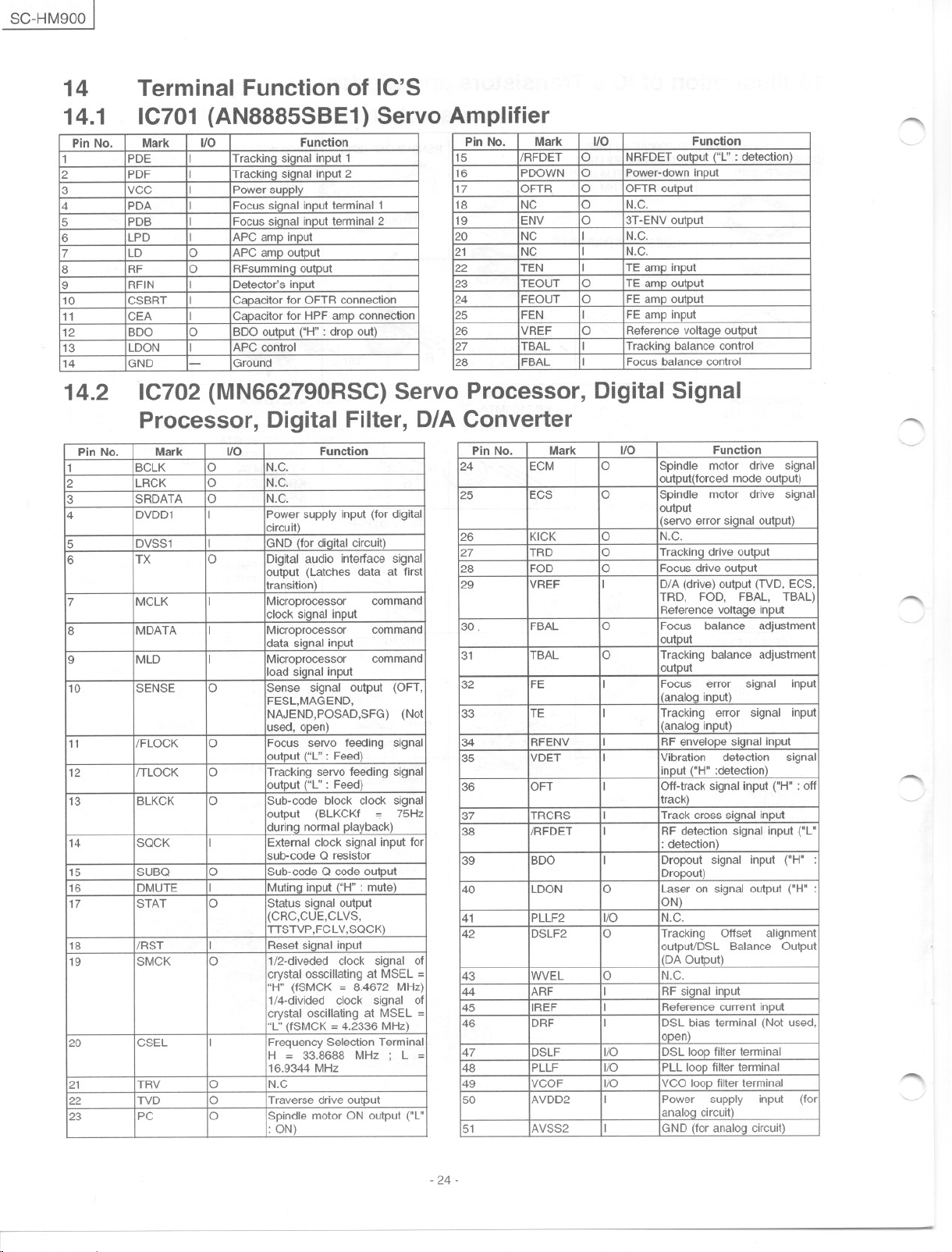
14
14.1
Pin No. Mark UO
1
2 PDF I
3 VCC I
4
5
6
7 LD O
8 RF O
9 RFIN
10 CSBRT
11
12 BDO O
13 LDON
14 GND
14.2
Terminal Function of IC'S
IC701 (AN8885SBE1) Servo Amplifier
PDE
PDA I
PDB I
LPD I
CEA
IC702 (MN662790RSC) Servo Processor, Digital Signal
I
Tracking signal input 1
Trackin¡:¡ signal input 2
Power supply
Focus signal input terminal 1
Focus signal input terminal 2
APC amp input
APC amp output
RFsummin¡:¡ output
I Detector's input
I
Capacitar for OFTR connection
I
Capacitar for HPF amp connection
BDO output ("H" : drop out)
I APC control
-
Ground
Processor, Digital Filter, D/A Converter
Pin No.
1 BCLK O N.C.
2
3
4
5 DVSS1
6
7 MCLK
8
9 MLD
10 SENSE O
11
12 /TLOCK
13
14 SQCK
15 SUBO O
16 DMUTE
17 STAT O
18 /RST 1
19
20 CSEL
21 TRV O N.C
22
23 PC
Mark UD
LRCK O
SRDATA O N.C.
DVDD1
TX
MDATA
/FLOCK
BLKCK O
SMCK O
TVD O
I
I
O
I
I
I
O
O
I
I
I
O
Function
Function
N.C.
Power supply input (for digital
circuit)
GND (for digital circuit)
Digital audio interface signal
output (Latches data at first
transition)
Microprocessor
clock signal input
Microprocessor
data si¡:¡nal input
Microprocessor
load signal input
Sense
signal output (OFT,
FESL,MAGEND,
NAJEND,POSAD,SFG) (Not
usad, open)
Focus servo feeding signal
output ("L" : Feed)
Tracking servo feeding signal
output ("L" : Feed)
Sub-cede block clock signal
output (BLKCKf
during normal playback)
External clock signal input for
sub-coda Q resistor
Sub-cede Q coda output
Muting input ("H" : muta)
Status signal output
(CRC,CUE,CLVS,
TTSTVP,FCLV,SOCK)
Reset signal input
1/2-diveded clock signal of
crystal osscillating at MSEL =
"H" (fSMCK = 8.4672 MHz)
1/4-divided clock
crystal oscillating at MSEL =
"L" (fSMCK = 4.2336 MHz)
Frequency Selection Terminal
H = 33.8688 MHz ;
16.9344 MHz
Traverse drive output
Spindle motor ON output ("L"
: eN)
command
command
command
75Hz
signal
L =
Pin No. Mark 1/0
15 /RFDET
16
17 OFTR O
18
19
20 NC
21
22 TEN
23
24 FEOUT O
25 FEN
26
27 TBAL
28 FBAL
Pin No.
24 ECM O
25
26 KICK O
27 TRD O
28 FOD O
29
30.
31
32
33
34 RFENV
35
36 OFT 1
37 TRCRS
38 /RFDET
39
40 LDON O
41
42 DSLF2 O
43
of
44
45
46
47 DSLF l/O
48 PLLF l/O
49 VCOF l/O
50 AVDD2 I
51 AVSS2
Function
O
NRFDET output ("L" : deleGUen)
PDOWN
NC
ENV
NC
TEOUT O
VREF
ECS
VREF
FBAL O Focus
TBAL O
FE
TE
VDET I Vibration detection
BDO
PLLF2 l/O N.C.
WVEL O N.C.
ARF 1
IREF 1
DRF I
O
Power-down input
OFTR output
N.C.
O
O
3T-ENV output
I N.C.
I N.C.
I
TE amp input
TE amp output
FE amp output
I
FE amp input
O
Reference voltage output
I
Tracking balance control
I Focus balance control
Mark 1/0 Function
Spindle
O
I
I
I
1
I
I
I
I
output(forced moda output)
Spindle
output
(servo error signal output)
N.C.
Tracking drive output
Focus drive output
D/A (drive) output (TVD, ECS,
TRD,
Reference voltage input
output
Tracking balance adjustment
output
Focus error
(analog input)
Tracking
(analog input)
RF envelope signal input
input ("H" :detection)
Qff-track signal input ("H" : off
track)
Track cross signal input
RF detection signal input ("L"
: detection)
Dropout signal input ("H" :
Dropout)
Laser on signal output ("H" :
eN)
Tracking
output/DSL Balance Output
(DA Output)
RF signal input
Reference current input
DSL bias terminal (Not usad,
open)
DSL loop filler terminal
PLL loop filter terminal
VCO loop filter terminal
Power
analog circuit)
GND (for analog circuit)
motor
motor drive
FOD,
balance
error
Offset
supply
drive
signal
signal
FBAL,
TBAL)
adjustment
signal input
signal
signal
alignment
input (for
~
"'"'"
'
-"""""'"
/
input
"'""
-.
'---
-24-
t SC-HM900
-
1
", ,
Pin No. Mark ./0 Function
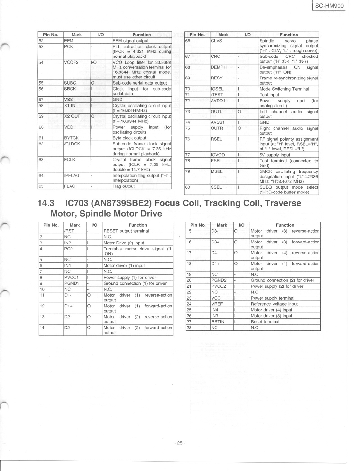
52 EFM
53 PCK
54 VCOF2 1/0
55
56
57
58
59 X2 OUT O
60
61 BYTCK
62
63 FCLK
64 IPFLAG
65 FLAG
SUBC O
SBCK I Clock
VSS I GNO
X1 IN I
VDO I
/CLOCK
-
-
-
-
-
-
-
EFMsignaloutput
PLL extraction dock output
(fPCK = 4.321
normal playback)
VCO Loop filler tor 33.8688
MHz conversation terminal for
16.9344 MHz crystal moda,
must use other circuit
Sub-coda serial data output
input
serial data
Crystal oscillating circuit input
!(f = 16.9344MHz)
Crystal oscillating circuit input
(f = 16.9344 MHz)
Power
oscillating circuit)
Byte clock output
Sub-coda trame dock signal
output (fCLOCK = 7.35 kHz
during normal playback)
Crystal
output (fCLK = 7.35
double = 14.7 kHz)
Interpolation flag output ("H" :
Interpolation)
Flag output
supply input (tor
trame clock
MHz during
tor sub-coda
signal
kHz,
Pin No. Mark ./0 Function
66
67
68
69
70
71
72 AVO01 I
73 OUTL O Left channel audio
74 AVSS1 I GND
75 OUTR O
76
77
78
79 MSEL
80 SSEL
CLVS
CRC
OEMPH
RESY
lOSEL
/TEST
RSEL I
laVaD
PSEL I
-
-
-
-
I
I
I
I
I
Spindle
synchronizing signal output
("H" : CLV, "L" : rough servo)
Sub-coda CRC checked
output ("H':OK,"L" :NG)
Oe-emphassis
output ("H" :ON)
Frame re-synchronizing signal
output
Mode Switching Terminal
Test input
Power
analog circuit)
output
Right channel audio signal
output
RF signal polarity assignment
input (at "H" level, RSEL="H",
at "L" level, RESL="L")
5V supply input
Test terminal (connected to
Gnd)
SMCK oscillating trequency
designation input ("L":4.2336
MHz, "H":8.4672 MHz)
SUBO output
("H":O-code buffer
servo
ON
supply input (tor
moda select
phase
signaJ
signal
moda)
r
r-
r¡
14.3 IC703 (AN8739SBE2) Focus Coil, Tracking Coil, Traverse
Mot9r, Spindle Motor Drive
Pin No. Mark ./0 Function
1
2
3 IN2
4
5 NC
/RST
NC
PC2 I
6 IN1 I
7
8
9
10
11
NC
PVCC1 I
PGN01
NC
01- O
-
RESET output terminal
-
N.C.
I
Motor Orive (2) input
Turntable motor drive signal ("L
:ON)
-
N.C.
Motordriver (1)input
I
N.C.
Powersupply(1)tordriver
-
Groundconnection(1) tordriver
-
N.C.
Motor driver
output
12 01+ O Motor
driver
output
13 02-
O
Motor driver
output
14
02+
O Motor driver
output
reverse-action
(1)
torward-action
(1)
reverse-action
(2)
forward-action
(2)
Pin No. Mark ./0 Function
15
16
17
18
19
20
21 PVCC2 I
22
23
24 VREF I
25 IN4 I
26 IN3
27 RSTIN
28
03- O Motor driver
03+
04- O Motor driver
04+ O Motor driver
NC
PGN02
NC
VCC
NC
output
O
Motor driver
output
output
output
-
N.C.
-
Groundconnection(2)tor driver
power supply(2)tor driver
-
N.C.
I
Power supply terminal
Reterence voltage input
Motor driver (4) input
I
Motor driver (3) input
I
Reset terminal
-
N.C.
reverse-actjon
(3)
torward-action
(3)
reverse-action
(4)
forward-action
(4)
r
-25-
 Loading...