

Panasonic SC-HC49EG Service Manual
© Panasonic Corporation 2014. All rights reserved.
Unauthorized copying and distribution is a violation of
law.
PSG1402001CE
Compact Stereo System
Model No. SC-HC49EG
Product Color: (K)...Black Type
(S)...Silver Type
(W)...White Type
TABLE OF CONTENTS
PAGE PAGE
1 Safety Precautions----------------------------------------------- 3
1.1. General Guidelines---------------------------------------- 3
1.2. Before Repair and Adjustment------------------------- 4
1.3. Protection Circuitry---------------------------------------- 4
1.4. Caution For Fuse Replacement------------------------ 4
1.5. Safety Part Information----------------------------------- 4
2 Warning-------------------------------------------------------------- 5
2.1. Prevention of Electrostatic Discharge (ESD)
to Electrostatically Sensitive (ES) Devices---------- 5
2.2. Precaution of Laser Diode------------------------------- 6
2.3. Service caution based on Legal restrictions-------- 7
2.4. Handling Precaution for Traverse Unit--------------- 8
3 Service Navigation----------------------------------------------- 9
3.1. Service Information --------------------------------------- 9
4 Specifications ----------------------------------------------------10
5 Location of Controls and Components ------------------11
5.1. Main Unit & Remote Control Key Button
Operations------------------------------------------------- 11
6 Service Mode-----------------------------------------------------12
6.1. Self Diagnostic Table------------------------------------12
6.2. Self Diagnostic Function Error Code----------------13
6.3. Doctor Mode Table--------------------------------------- 14
7 Troubleshooting Guide ---------------------------------------16
8 Disassembly and Assembly Instructions---------------17
8.1. Service Fixture & Tools ---------------------------------17
8.2. Disassembly flow chart--------------------------------- 18
8.3. Types of Screws------------------------------------------19
8.4. Main Parts Location Diagram------------------------- 19
8.5. Disassembly of Base Stand Assembly ------------- 20
8.6. Disassembly of Front Ornament Unit (L) & (R)---20
8.7. Disassembly of Door Unit------------------------------21
8.8. Disassembly of Door Base ---------------------------- 21

2
8.9. Disassembly of Front Panel Block-------------------22
8.10. Replacement of iPod Block----------------------------23
8.11. Disassembly of Bridge P.C.B.-------------------------30
8.12. Disassembly of Motor P.C.B.--------------------------30
8.13. Disassembly of Gear Block & Arm Spring
(Top) -------------------------------------------------------- 31
8.14. Disassembly of Arm Spring, Gear Assembly &
Arm Assembly -------------------------------------------32
8.15. Replacement of Gear Assembly ---------------------33
8.16. Replacement of Arm Assembly-----------------------35
8.17. Disassembly of Cam Rail Top & Door Slider
Top-----------------------------------------------------------36
8.18. Disassembly of Cam Rail Bottom & Door
Slider Bottom----------------------------------------------37
8.19. Disassembly of NFC P.C.B. ---------------------------38
8.20. Disassembly of SMPS Unit----------------------------39
8.21. Disassembly of SMPS P.C.B. -------------------------40
8.22. Disassembly of FL P.C.B. & Button Ornament
Unit-----------------------------------------------------------41
8.23. Disassembly of Button P.C.B.-------------------------42
8.24. Disassembly of CD Mechanism ----------------------42
8.25. Disassembly of CD Interface P.C.B.-----------------43
8.26. Disassembly of Main P.C.B.---------------------------45
8.27. Disassembly of Front Speaker (SP1)--------------- 46
8.28. Disassembly of Front Speaker (SP2)--------------- 47
8.29. Disassembly of Passive Radiator Unit (SP3) -----48
8.30. Disassembly of Passive Radiator Unit (SP4) -----49
8.31. Disassembly of Jack Lid--------------------------------49
9 Service Position-------------------------------------------------51
9.1. Checking of SMPS P.C.B.------------------------------51
9.2. Checking of FL P.C.B.-----------------------------------52
9.3. Checking of CD Interface P.C.B. ---------------------54
9.4. Checking of Main P.C.B.--------------------------------55
10 Block Diagram ---------------------------------------------------59
10.1. SYSTEM CONTROL (1/2) BLOCK DIAGRAM --- 59
10.2. SYSTEM CONTROL (2/2) BLOCK DIAGRAM --- 60
10.3. AUDIO BLOCK DIAGRAM ----------------------------61
10.4. POWER SUPPLY (1/2) BLOCK DIAGRAM ------- 62
10.5. POWER SUPPLY (2/2) BLOCK DIAGRAM ------- 63
11 Wiring Connection Diagram--------------------------------- 64
12 Schematic Diagram---------------------------------------------65
12.1. Schematic Diagram Notes-----------------------------65
12.2. CD INTERFACE CIRCUIT-----------------------------67
12.3. MAIN (MICON) CIRCUIT (1/2)------------------------68
12.4. MAIN (MICON) CIRCUIT (2/2)------------------------69
12.5. MAIN (SUPPLY) CIRCUIT-----------------------------70
12.6. MAIN (CD) CIRCUIT ------------------------------------71
12.7. MAIN (DAMP) CIRCUIT--------------------------------72
12.8. MAIN (TUNER) CIRCUIT ------------------------------73
12.9. MAIN (iPod_USB) CIRCUIT---------------------------74
12.10. BRIDGE, MOTOR & BUTTON CIRCUIT-----------75
12.11. FL CIRCUIT -----------------------------------------------76
12.12. SMPS CIRCUIT ------------------------------------------77
12.13. iPod DOCK CIRCUIT -----------------------------------78
13 Printed Circuit Board ------------------------------------------79
13.1. CD INTERFACE, BRIDGE & iPod DOCK
P.C.B.--------------------------------------------------------79
13.2. MAIN P.C.B. (Side A)------------------------------------80
13.3. MAIN P.C.B. (Side B)------------------------------------81
13.4. MOTOR, FL & BUTTON P.C.B. ----------------------82
13.5. SMPS P.C.B. ----------------------------------------------83
14 Appendix Information of Schematic Diagram -------- 85
14.1. Voltage Measurement & Waveform Chart--------- 85
15 Exploded View and Replacement Parts List----------- 89
15.1. Exploded View and Mechanical replacement
Parts List--------------------------------------------------- 89
15.2. Electrical Replacement Parts List ------------------- 95
3
1 Safety Precautions
1.1. General Guidelines
1. IMPORTANT SAFETY NOTICE
There are special components used in this equipment which are important for safety. These parts are marked by in the
Schematic Diagrams, Circuit Board Layout, Exploded Views and Replacement Parts List. It is essential that these critical parts
should be replaced with manufacturer’s specified parts to prevent X-RADIATION, shock, fire, or other hazards. Do not modify
the original design without permission of manufacturer.
2. An Isolation Transformer should always be used during the servicing of AC Adaptor whose chassis is not isolated from the AC
power line. Use a transformer of adequate power rating as this protects the technician from accidents resulting in personal
injury from electrical shocks. It will also protect AC Adaptor from being damaged by accidental shorting that may occur during
servicing.
3. When servicing, observe the original lead dress. If a short circuit is found, replace all parts which have been overheated or
damaged by the short circuit.
4. After servicing, see to it that all the protective devices such as insulation barriers, insulation papers shields are properl y
installed.
5. After servicing, make the following leakage current checks to prevent the customer from being exposed to shock hazards.
1.1.1. Leakage Current Cold Check
1. Unplug the AC cord and connect a jumper between the two prongs on the plug.
2. measure the resistance value, with an ohmmeter between the jumpered AC plug and e ach exposed metallic cabinet part on
the equipment such as screwheads, connectors, control shafts, etc. When the exposed metallic part has a return path to the
chassis, the reading should be between 1MΩ and 5.2MΩ. When the exposed metal does no t have a return path to the chas-
sis, the reading must be
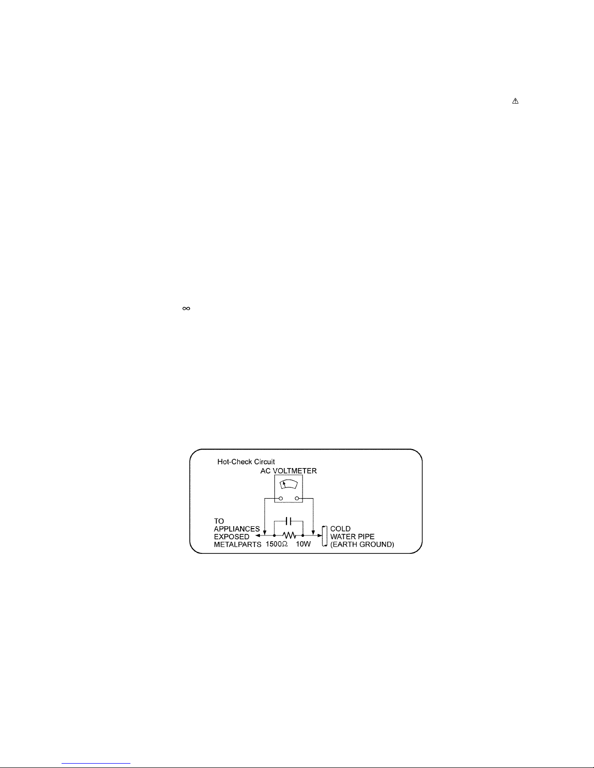
1.1.2. Leakage Current Hot Check
1. Plug the AC cord directly into the AC outlet. Do not use an isolation transformer for this check.
2. Connect a 1.5kΩ, 10 watts resistor, in parallel with a 0.15μF capacitors, between each exposed metallic part on the set and a
good earth ground such as a water pipe, as shown in Figure 1-1.
3. Use an AC voltmeter, with 1000 ohms/volt or more sensitivity, to measure the potential across the resistor.
4. Check each exposed metallic part, and measure the voltage at each point.
5. Reverse the AC plug in the AC outlet and repeat each of the above measurements.
6. The potential at any point should not exceed 0.75 volts RMS. A leakage current tester (Simpson Model 229 or equivalent)
may be used to make the hot checks, leakage current must not exceed 1/2 milliamp. In case a measurement is outside of the
limits specified, there is a possibility of a shock hazard, and the equipment should be repaired and rechecked before it is
returned to the customer.
Figure. 1-1
4
1.2. Before Repair and Adjustment
Disconnect AC power, discharge unit AC Capacitors (C1702, C1710, C1725, C1727 and C1728) through a 10W, 1W resistor to
ground.
Caution : DO NOT SHORT-CIRCUIT DIRECTLY (with a screwdriver blade, for instance), as this may destroy solid state devices.
After repairs are completed, restore power gradually using a variac, to avoid overcurrent.
• Current consumption at AC 240V, at 50Hz in NO SIGNAL mode (at volume minimum in FM Tuner mode) should be ~200 mA.
1.3. Protection Circuitry
The protection circuitry may have operated if either of the following conditions are noticed:
• No sound is heard when the power is turned on.
• Sound stops during a performance.
The function of this circuitry is to prevent circuitry damage if, for example, the positive and negative speaker connection wires are
"shorted", or if speaker systems with an impedance less than the indicated rated impedance of the amplifier are used.
If this occurs, follow the procedure outlines below:
1. Turn off the power.
2. Determine the cause of the problem and correct it.
3. Turn on the power once again after one minute.
Note:
When the protection circuitry functions, the unit will not operate unless the power is first turned off and then on again.
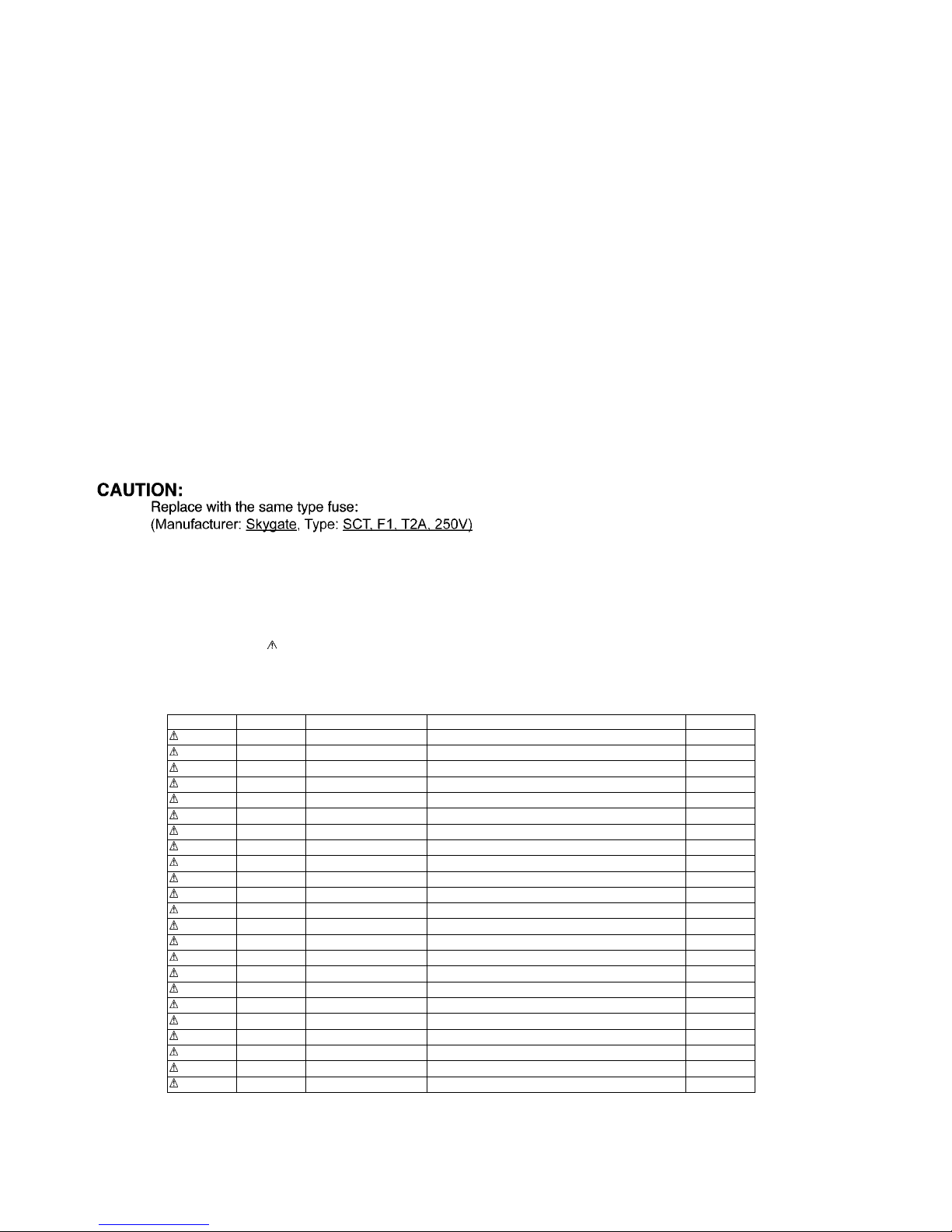
1.4. Caution For Fuse Replacement
1.5. Safety Part Information
Safety Parts List:
There are special components used in this equipment which are important for safety.
These parts are marked by in the Schematic Diagrams, Exploded View & Replacement Parts List. It is essential that these
critical parts should be replaced with manufacturer’s specified parts to prevent shock, fire or other hazards. Do not modify the
original design without permission of manufacturer.
Safety Ref. No. Part No. Part Name & Description Remarks
17 RGP1681A-K1 REAR CABINET K/S
17 RGP1681A-W1 REAR CABINET W
49 RMV0429 SMPS BRACKET INSULATOR A
51 RMV0432 SMPS COVER INSULATION
301 RAE5306Z-V TRAVERSE UNIT
A2 K2CQ2YY00119 AC CORD
A3 RQT9884-1D O/I BOOK (Ge/Fr/It/Du)
A3 RQT9885-1E O/I BOOK (Sw/Da/Fi)
A3 RQT9886-1R O/I BOOK (En/Po/Cz/Sp)
C1702 F0CAF224A105 0.22uF
C1710 F1BAF471A013 470pF
C1725 F0CAF104A105 0.1uF
C1727 F1BAF1020020 1000pF
C1728 F1BAF1020020 1000pF
F1 K5G202Y00006 FUSE
L1702 G0B922G00002 LINE FILTER
P1751 K2AA2B000011 AC INLET
PC1702 B3PBA0000579 PHOTO COUPLER
PCB7 REP5054CA SMPS P.C.B. (RTL)
R1724 ERJ12YJ105U 1M 1/2W
R1726 ERJ12YJ105U 1M 1/2W
T1700 G4DYZ0000077 TRANSFORMER
Z1752 ERZV10V511CS VARISTOR
5
2Warning
2.1. Prevention of Electrostatic Discharge (ESD) to Electrostatically Sensitive (ES) Devices
Some semiconductor (solid state) devices can be damaged easily by static electricity. Such components commonly are called Electrostatically Sensitive (ES) Devices.
The following techniques should be used to help reduce the incidence of component damage caused by electrostatic discharge
(ESD).
1. Immediately before handling any semiconductor component or semiconductor-equipped assembly, drain off any ESD on your
body by touching a known earth ground. Alternatively, obtain and wear a commercially available discharging ESD wrist strap,
which should be removed for potential shock reasons prior to applying power to the unit under test.
2. After removing an electrical assembly equipped with ES devices, place the assembly on a conductive surface such as al uminum foil, to prevent electrostatic charge buildup or exposure of the assembly.
3. Use only a grounded-tip soldering iron to solder or unsolder ES devices.
4. Use only an anti-static solder removal device. Some solder removal devices not classified as “anti-static (ESD protected)” can
generate electrical charge sufficient to damage ES devices.
5. Do not use freon-propelled chemicals. These can generate electrical charges sufficient to damage ES devices.
6. Do not remove a replacement ES device from its protective package until immediately before you are ready to install it. (Most
replacement ES devices are packaged with leads electrically shorted together by conductive foam, aluminum foil or comparable conductive material).
7. Immediately before removing the protective material from the leads of a replacement ES device, touch the protective material
to the chassis or circuit assembly into which the device will be installed.
CAUTION:
Be sure no power is applied to the chassis or circuit, and observe all other safety precautions.
8. Minimize bodily motions when handling unpackaged replacement ES devices. (Otherwise harmless motion such as the
brushing together of your clothes fabric or the lifting of your foot from a carpeted floor can generate static electricity (ESD) sufficient to damage an ES device).
6
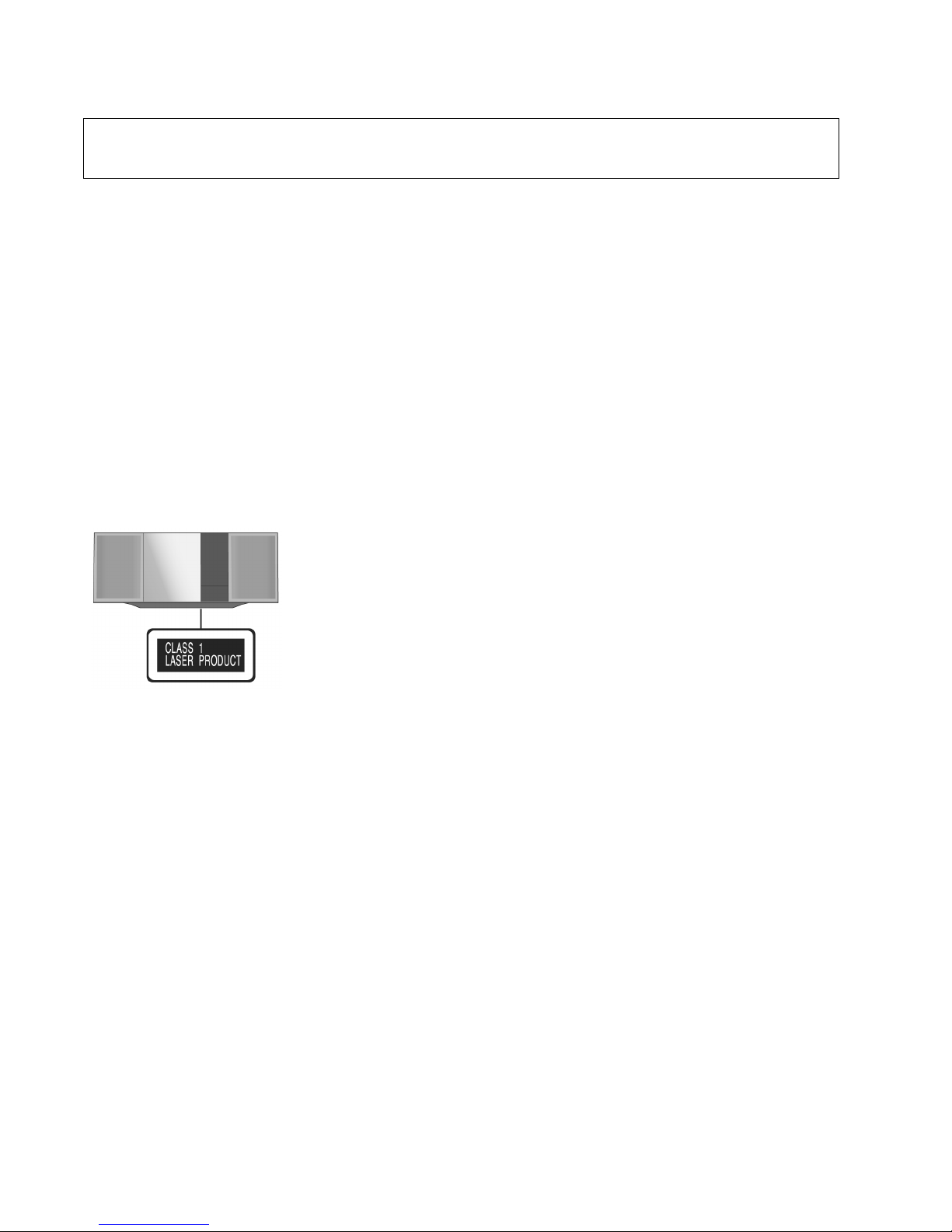
2.2. Precaution of Laser Diode
Caution:
This product utilizes a laser diode with the unit turned "on", invisible laser radiation is emitted from the pickup lens.
Wavelength: 790 nm (CD)
Maximum output radiation power from pick up : 10 0 μW/VDE
Laser radiation from the pickup unit is safety level, but be sure the followings:
1. Do not disassemble the pickup unit, since radiation from exposed laser diode is dangerous.
2. Do not adjust the variable resistor on the pickup unit. It was already adjusted.
3. Do not look at the focus lens using optical instruments.
4. Recommend not to look at pickup lens for a long time.
ACHTUNG :
Dieses Produkt enthält eine Laserdiode. Im eingeschalteten Zustand wird unsichtbare Laserstrahlung von der Lasereinheitadgestrahit.
Wellenlänge : 790nm (CD)
Maximale Strahlungsleistung der Lasereinheit :100 μW/VDE
Die Strahlung an der Lasereinheit ist ungefährlich, wenn folgende Punkte beachtet werden:
1. Die Lasereinheit nicht zerlegen, da die Strahlung an der freigelegten Laserdiode gefährlich ist.
2. Den werkseitig justierten Einstellregler der Lasereinhit nicht verstellen.
3. Nicht mit optischen Instrumenten in die Fokussierlinse blicken.
4. Nicht über längere Zeit in die Fokussierlinse blicken.
CAUTION!
THIS PRODUCT UTILIZES A LASER.
USE OF CONTROLS OR ADJUSTMENTS OR PERFORMANCE OF PROCEDURES OTHER THAN THOSE SPECIFIED HEREIN MAY RESULT
IN HAZARDOUS RADIATION EXPOSURE.
7
2.3. Service caution based on Legal restrictions
2.3.1. General description about Lead Free Solder (PbF)
The lead free solder has been used in the mounting process of all ele ctrical components on the printed circuit boards used for this
equipment in considering the globally environmental conservation.
The normal solder is the alloy of tin (Sn) and lead (Pb). On the other hand, the lead free solder is the alloy mainly consists of tin
(Sn), silver (Ag) and Copper (Cu), and the melting point of the lead free solder is higher approx.30 degrees C (86°F) more than that
of the normal solder.
Definition of PCB Lead Free Solder being used
Service caution for repair work using Lead Free Solder (PbF)
• The lead free solder has to be used when repairing the equipment for which the lead free solder is used.
(Definition: The letter of “PbF” is printed on the PCB using the lead free solder.)
• To put lead free solder, it should be well molten and mixed with the original lead free solder.
• Remove the remaining lead free solder on the PCB cleanly for soldering of the new IC.
• Since the melting point of the lead free solder is higher than that of the normal lead solder, it takes the longer time to melt the
lead free solder.
• Use the soldering iron (more than 70W) equipped with the temperature control after setting the temperature a t 350±30 deg rees
C (662±86°F).
Recommended Lead Free Solder (Service Parts Route.)
• The following 3 types of lead free solder are available through the service parts route.
RFKZ03D01K-----------(0.3mm 100g Reel)
RFKZ06D01K-----------(0.6mm 100g Reel)
RFKZ10D01K-----------(1.0mm 100g Reel)
Note
* Ingredient: Tin (Sn), 96.5%, Silver (Ag) 3.0%, Copper (Cu) 0.5%, Cobalt (Co) / Germanium (Ge) 0.1 to 0.3%
The letter of “PbF” is printed either foil side or components side on the PCB using the lead free solder.
(See right figure)
8
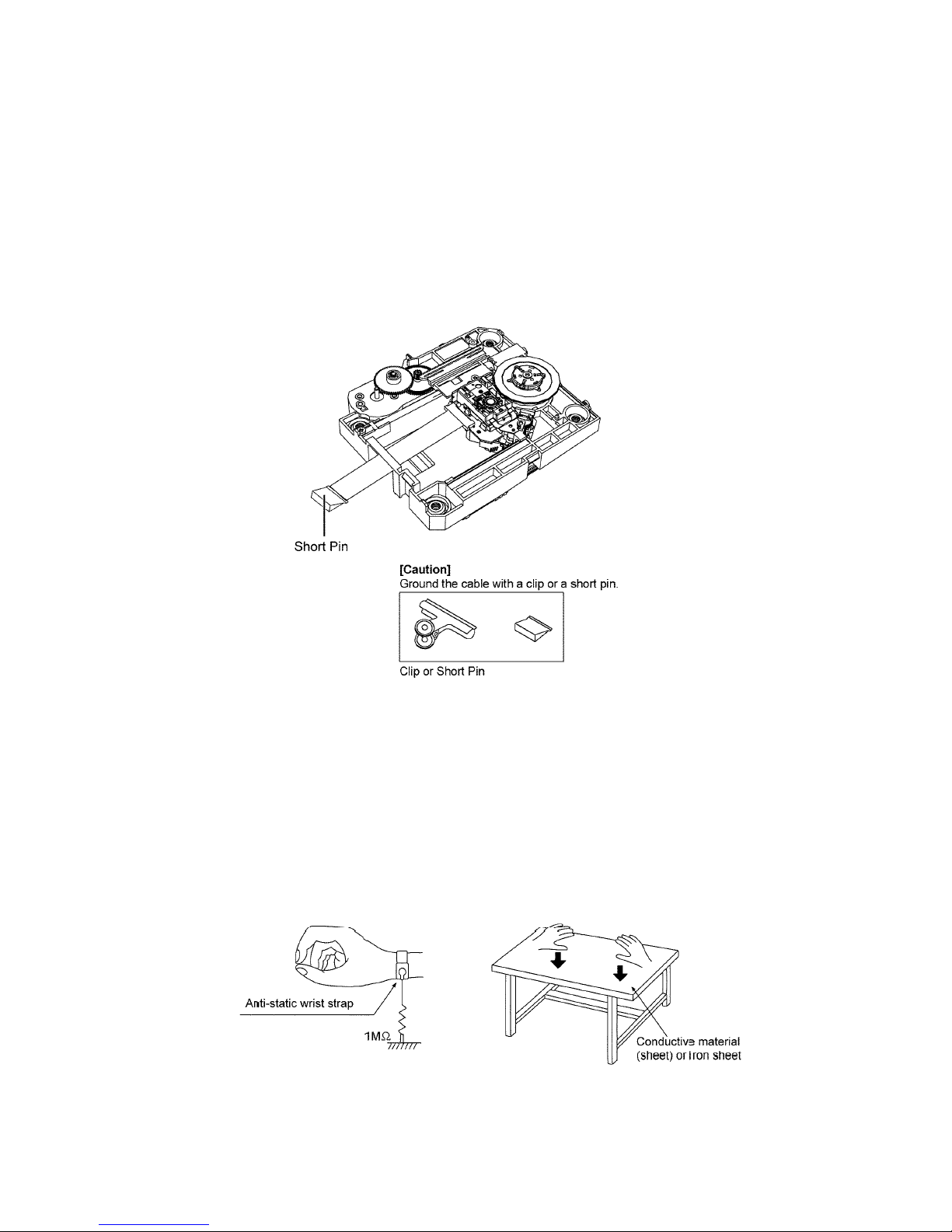
2.4. Handling Precaution for Traverse Unit
The laser diode in the optical pickup unit may break down due to static electricity of clothes or human body. Special care must be
taken avoid caution to electrostatic breakdown when servicing and handling the laser diode in the Traverse Unit.
2.4.1. Cautions to Be Taken in Handling the Optical Pickup Unit
The laser diode in the optical pickup unit may be damaged due to electrostatic discharge generating from clo thes or human body.
Special care must be taken avoid caution to electrostatic discharge damage when servicing the laser diode.
1. Do not give a considerable shock to the optical pickup unit as it has an extremely high-precise structure.
2. To prevent the laser diode fro m the electrostatic discharge damage, the flexible cable of the optical pickup unit removed
should be short-circuited with a short pin or a clip.
3. The flexible cable may be cut off if an excessive force is applied to it. Use caution when handling the flexible cable.
4. The antistatic FPC is connected to the new optical pickup unit. After replacing the optical pickup unit and connecting the flexible cable, cut off the antistatic FPC.
2.4.2. Grounding for electrostatic breakdown prevention
Some devices such as the CD player use the optical pickup (laser diode) and the optical pickup will be damaged by static electricity
in the working environment. Proceed servicing works under the working environment where grounding works is completed.
2.4.2.1. Worktable grounding
1. Put a conductive material (sheet) or iron sheet on the area where the optical pickup is placed , and ground the sheet.
2.4.2.2. Human body grounding
1. Use the anti-static wrist strap to discharge the static electricity form your body.

9
3 Service Navigation
3.1. Service Information
This service manual contains technical information which will allow service personnel’s to understand and service this model.
Please place orders using the parts list and not the drawing reference numbers.
If the circuit is changed or modified, this information will b e fol lowed by supplemen t service manual to be filed with original se rvice
manual.
Note : In case either NFC P.C.B. or EEPCOM IC (IC8004) on Main P.C.B. should break down, they need to be replaced at the same
time as a pair.
The following optional replacement methods are prepared and provided depending on circumstances.
1. NFC P.C.B. / EEPCOM IC (IC8004) kit supply.
Part No. RFKV5053DB
Replace the EEPCOM IC (IC8004) and NFC P.C.B. at the same time.
2. NFC P.C.B. / MAIN P.C.B. kit supply.
Part No. RFKV5053DA
Replace the Main P.C.B. and NFC P.C.B. at the same time.

10
4 Specifications
Q General
Power consumption 37 W
Power consumption in standby
mode*
1, 2
Approx. 0.2 W
(when “BLUETOOTH STANDBY” is “ON”)*
2
Approx. 0.3 W
Power supply AC 220 V to 240 V, 50 Hz
Dimensions (W x H x D) 500 mm x 205 mm x 92 mm
Mass (weight) Approx. 2.5 kg
Operating temperature range 0 °C to +40 °C
Operating humidity range 35% to 80 % RH
(no condensation)
Q Amplifier Section
Output power:
RMS Output Power Stereo Mode
Front Ch (both ch driven) 20 W per channel (8 Ω),
1 kHz, 10% THD
Total RMS Stereo mode power 40 W
Q Tuner section
Preset Memory FM 30 stations
Frequency modulation (FM)
Frequency range 87.50 MHz to 108.00 MHz
(50 kHz step)
Antenna terminals 75 Ω (unbalanced)
Q Disc Section
Disc played [8 cm or 12 cm]
CD, CD-R/RW (CD-DA, MP3*
3
)
Pick up
Wavelength 790 nm (CD)
Q Speaker System Section
Speaker unit(s)
Full range 6.5 cm Cone type x 1
per channel
Passive Radiator 8 cm x 2 per channel
Impedance 8 Ω
Q Terminal Section
Dock connection DC OUT 5 V 1.0 A
Port connection DC OUT 5 V 2.1 A
USB Standard USB 2.0 full speed
Media file format support MP3 (*.mp3)
USB device file system FAT12, FAT16, FAT32
Q Bluetooth Section
Version Ver2.1+EDR
Class Class 2
Supported profiles A2DP, AVRCP
Operating Frequency 2402 MHz to 2480 MHz
Operation distance 10 m Line of sight
• Specifications are subject to change without notice.
• Mass and dimensions are approximate.
• Total harmonic distortion is measured by a digital spectrum analyzer.
*1: “BLUETOOTH STANDBY” is “OFF”.
*2: No device is connected to the DC OUT terminal before turning to
standby mode.
*3: MPEG-1 Layer 3, MPEG-2 Layer 3.
11
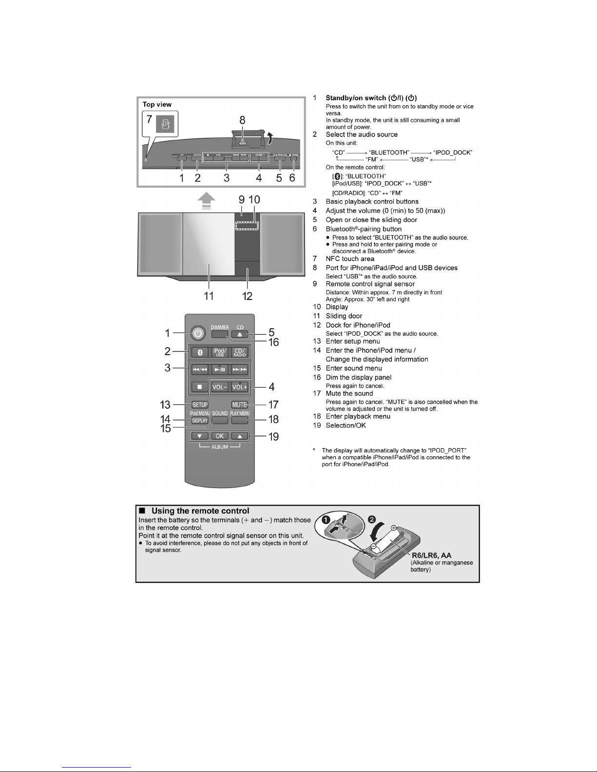
5 Location of Controls and Components
5.1. Main Unit & Remote Control Key Button Operations
12
6 Service Mode
This unit is equipped with features of self diagnostic & doctor mode setting for checking the functions & reliability.
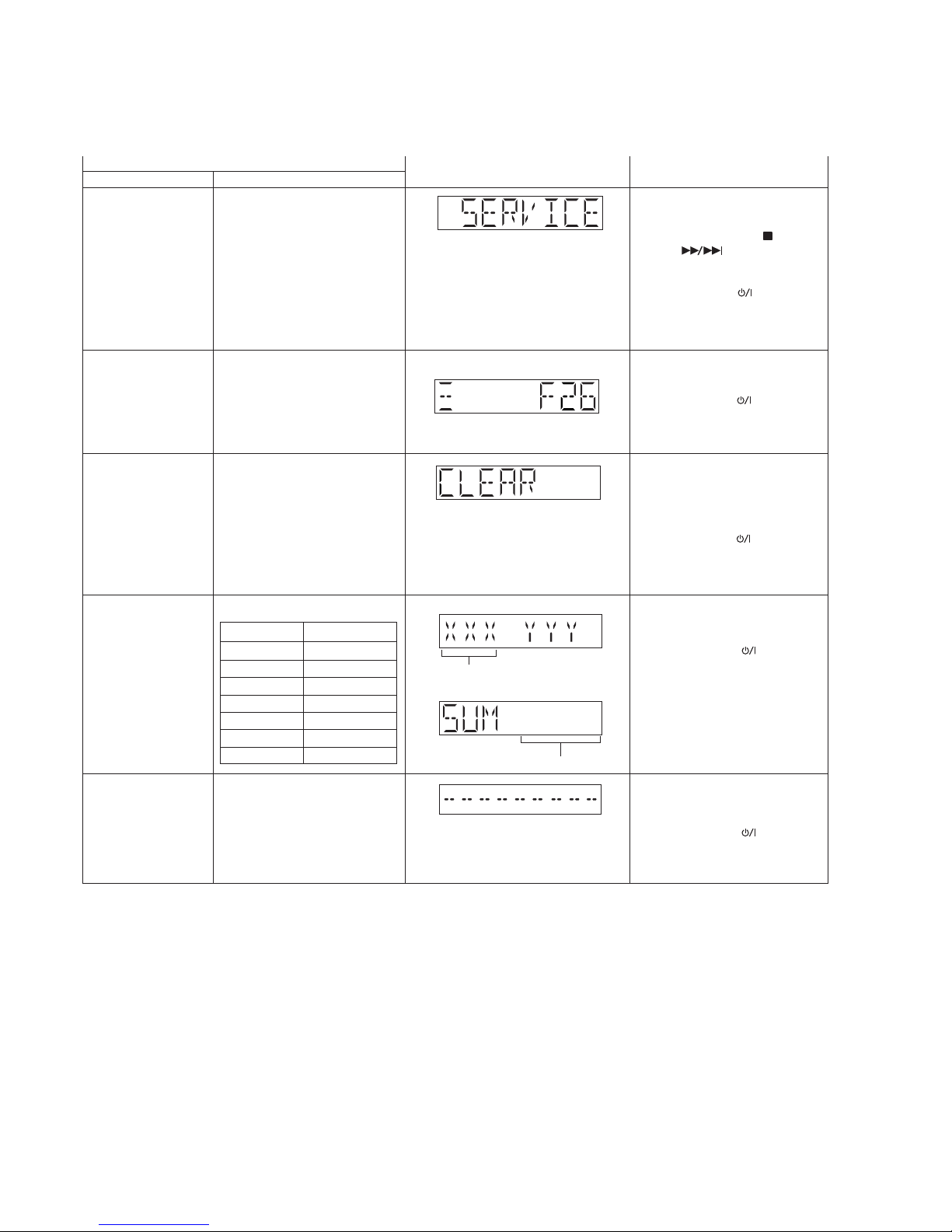
6.1. Self Diagnostic Table
Self Diagnostic Mode To enter into self diagnostic
checking
Item
FL display Key operation
Mode name Description
Error code information
Delete Error code
Example:
System will perform a check on
any unusual/error code from the
memory
To clear the stored in memory
(EEPROM IC)
Opecon version
Cold Start
To display model name & version
Model Name
HC49
HC39
HC29
HC19
HC49DB
HC39DB
HC29DB
Version display
_4AA
_4AB
_4AC
_4AD
_4AE
_4AF
_4AG
Step 1 : Select CD mode
(Ensure no disc is inserted).
Step 2 : Press and hold [ ] follow by
[ ] on main unit for 2
second .
• To exit, press the [TA] on the main
unit or using the remote control.
• Unplug the AC cord.
Step 1 : In self diagnostic mode,
Press [STOP] on main unit.
• To exit, press the [TA] on the main
unit or using the remote control.
• Unplug the AC cord.
Step 1 : In self diagnosis mode,
press and hold [OK] on
remote control for more than
5 second.
• To exit, press the [TA] on the main
unit or using the remote control.
• Unplug the AC cord.
No Rom correction
Version display
(Display 1)
(Display 2)
Press [DISPLAY] button on the
remote control.
• To exit, press the [TA] on the main
unit or using the remote control.
• Unplug the AC cord.
Press [SETUP] button on the remote
control.
• To exit, press the [TA] on the main
unit or using the remote control.
• Unplug the AC cord.
To activate cold start upon next
power up.
(Backup data are initialized)
13
6.2. Self Diagnostic Function Error Code
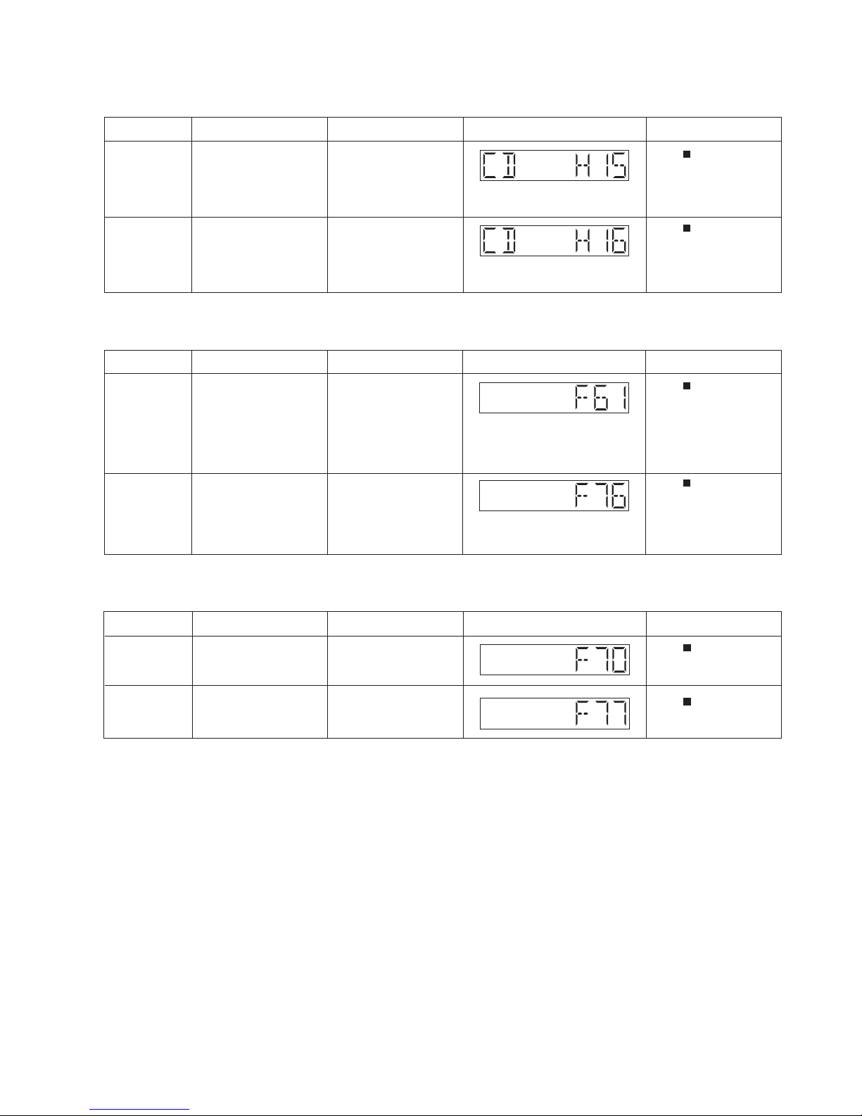
6.2.1. CD Mechanism Error Code Table
6.2.2. Power Amp Error Code Table
6.2.3. Bluetooth Error Code Table
of error Automatic FL Display Remarks
CD H15 CD Open Abnormal
Press [
] on main unit for
next error.
CD H16 CD Closing Abnormal
Press [
] on main unit for
next error.
Error Code Diagnostic Contents Description of error
During normal operation, if
“POS_SW_R (OPEN_SW)”
is not detected within 4~5
sec, “CD H15” shall be
memorized.
During closing operation, if
“POS_SW_CEN
(CLOSE_SW)” is not
detected within 4~5 sec,
“CD H16” shall be
memorized.
of error Automatic FL Display Remarks
F61
Press [
] on main unit for
next error.
Press [
] on main unit for
next error.
Error Code Diagnostic Contents Description of error
DAMP output abnormal PDET2 (DC_DET_AMP)= L
(NG). PDET2
(DC_DET_AMP) is
checked by reading the
input 2x20ms, F61 error
code shall be memorized
F76
Power supply abnormal PDET1 (DC_DET_PWR) = L
(NG). PDET1
(DC_DET_PWR) is checked
by reading the input 2x1ms,
F76 error code shall be
memorized.
of error Automatic FL Display Remarks
F70
Bluetooth Communication
Communication between
Bluetooth module and
micro-p abnormal
Press [
] on main unit for
next error.
F77
Bluetooth Address Error
If there is no valid Bluetooth
address stored in the
EEPROM IC
Press [
] on main unit for
next error.
Error Code Diagnostic Contents Description of error

14
6.3. Doctor Mode Table
Note : To enter the Doctor Mode, please use HC35 remote control. (Part No : N2QAYB000641)
Item
FL Display
Key Operation
Mode Name Description
Front Key
Doctor Mode
(Display 1)
(Display 2)
The Checksum of EEPROM and firmware
version will be display for 2 sec.
In any mode:
Press
[ ]
button on main unit follow by
[4] & then [7] on the remote control of
HC35.
•
To exit Doctor Mode, press
[TA]
button on main unit or on the remote
control of HC35.
• Unplug the AC cord.
In Doctor mode:
Press
[1]
button on the remote control
of HC35.
To cancel, press [0] button on remote
control of HC35. [CANCEL] will be
display and returns to Doctor Mode.
•
To exit Doctor Mode, press
[TA]
button on main unit or on the remote
control of HC35.
• Unplug the AC cord.
Opecon firmware version display
To enter into Doctor Mode for
checking of various items and
displaying EEPROM check sum
and Opecon firmware version
Note: The Opecon firmware
version as shown is an example.
It will be revised when there is
updates.
FL Display sequence Display
1¡2
Model Name
HC49
HC39
HC29
HC19
HC49DB
HC39DB
HC29DB
Version display
_4AA
_4AB
_4AC
_4AD
_4AE
_4AF
_4AG
FL Display Test
To check the FL segments
display (All segments will light
up)
In Doctor Mode:
Press [ ] follow by [2] & then [1]
button on the remote control of HC35.
To check the operation of sliding
Panel.
Sequence as follow :
1. CD Door set to CLOSE
position.
2. CD Door move to the left (CD
Open direction) and stop at
LEFT position for 1 sec.
3. CD Door move to the right
(CD Close direction) and stop at
CLOSE position for 1 sec.
4. All the process above is
considered as 1 cycle. Step (2) ~
(3) will repeat; Cycle Counter
display increase every 1 cycle
completed.
Mecha Sliding
Panel Reliability
•
To exit Doctor Mode, press
[TA]
button on main unit or on the remote
control of HC35.
• Unplug the AC cord.
To cancel, press [0] button on remote
control of HC35. [CANCEL] will be
display and returns to Doctor Mode.

15
Item
FL Display
Key Operation
Mode Name Description
Front Key
CD Traverse Test
Mode
In Doctor Mode:
Press [ ] follow by [1] & then [2]
button on the remote control of HC35.
The counter will increment by 1 until reach
99999999
To check for the traverse unit
operation. In this mode, the first &
last track is access & read.
(TOC). It fails when TOC is not
completed by 10s or the traverse
is out of focus. for more than 2s
•
To exit Doctor Mode, press
[TA]
button on main unit or on the remote
control of HC35.
• Unplug the AC cord.
•
To exit Doctor Mode, press
[TA]
button on main unit or on the remote
control of HC35.
• Unplug the AC cord.
Cold Start
The [NO DISC] display will appear after 2s,
In Doctor Mode:
Press [4] button on remote control.
To activate cold start upon next
power up.
(Backup data are initialized)
To cancel, press [0] button on remote
control of HC35. [CANCEL] will be
display and returns to Doctor Mode.
To cancel, press [0] button on remote
control of HC35. [CANCEL] will be
display and returns to Doctor Mode.

16
7 Troubleshooting Guide
This section is not available at the time of issue

17
8 Disassembly and Assembly Instructions
Caution Note:
• This section describes the disassembly and/or assembly procedures for all major printed circuit boards & main components for the unit. (You may refer to the section of “Main components and P.C.B Locations” as described in this service
manual)
• Before carrying out the disassembly process, please ensure all the safety precautions & procedures are followed.
• During the disassembly and/or assembly proc ess, please handle with care as there may be chassis components with
sharp edges.
• Avoid touching heatsinks due to its high temperature after prolong use.
• Be sure to use proper service tools , equipments or jigs during repair.
• Select items from the following indexes when disassembly or replacement are required.
• Disassembly of Base Stand Assembly
• Disassembly of Front Ornament Unit (L) & (R)
• Disassembly of Door Unit
• Disassembly of Door Base
• Disassembly of Front Panel Block
• Replacement of iPod Block
• Disassembly of Bridge P.C.B.
• Disassembly of Motor P.C.B.
• Disassembly of Gear Block & Arm Spring (Top)
• Disassembly of Arm Spring, Gear Assembly & Arm Assembly
• Replacement of Gear Assembly
• Replacement of Arm Assembly
• Disassembly of Cam Rail Top & Door Slider Top
• Disassembly of Cam Rail Bottom & Door Slider Bottom
• Disassembly of NFC P.C.B.
• Disassembly of SMPS Unit
• Disassembly of SMPS P.C.B.
• Disassembly of FL P.C.B. & Button Ornament Unit
• Disassembly of Button P.C.B.
• Disassembly of CD Mechanism
• Disassembly of CD Interface P .C.B.
• Disassembly of Main P.C.B.
• Disassembly of Front Speaker (SP1)
• Disassembly of Front Speaker (SP2)
• Disassembly of Passive Radiator Unit (SP3)
• Disassembly of Passive Radiator Unit (SP4)
• Disassembly of Jack Lid
8.1. Service Fixture & Tools
Prepare service tools before process service position.
Ref. No. Service Tools Remarks
SFT1 Main P.C.B. (P5003) - CD Interface P.C.B. (CN7002) REE1978 (24P FFC)
SFT2 Main P.C.B. (CN1100) - SMPS P.C.B. (P1700) REX1538 (7P Wire)
18
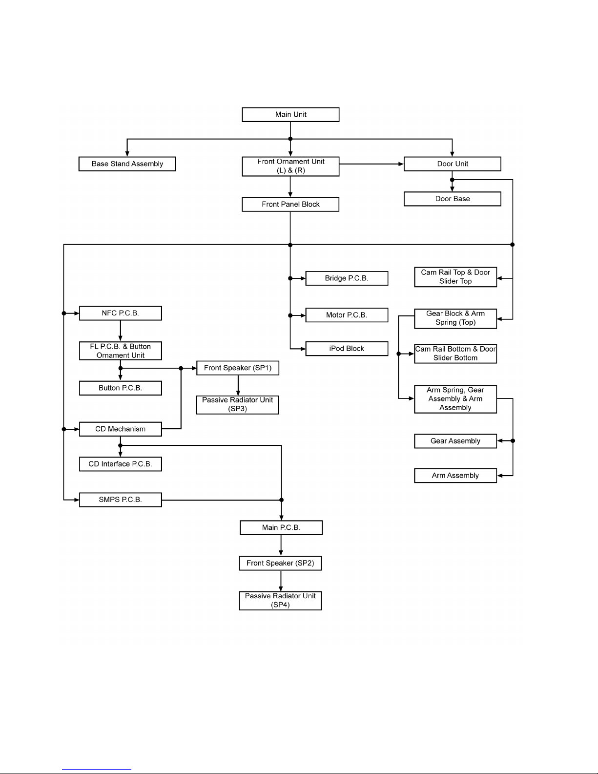
8.2. Disassembly flow chart
The following chart is the procedure for disassembling the casing and inside parts for internal inspection when carrying out the servicing.
To assemble the unit, reverse the steps shown in the chart below.
19
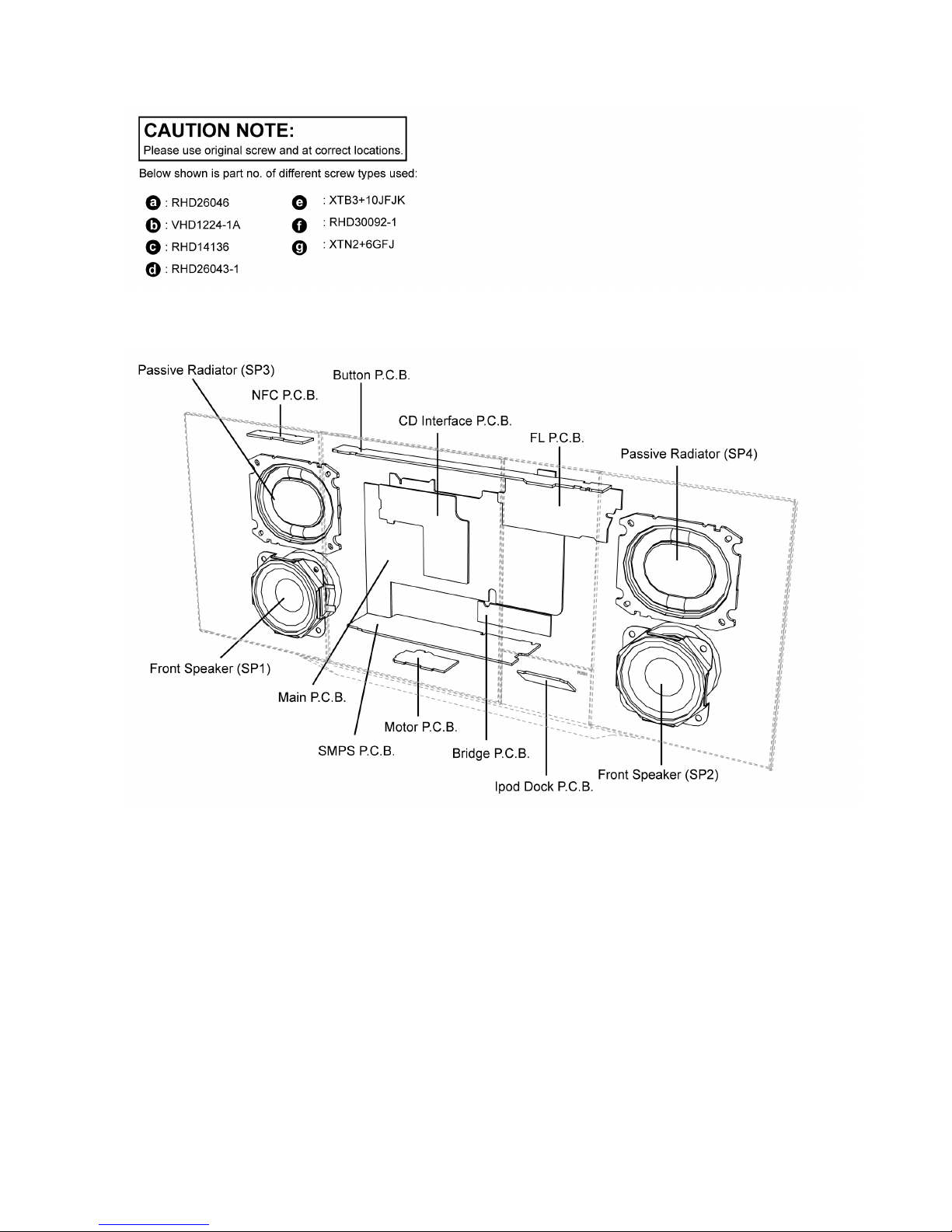
8.3. Types of Screws
8.4. Main Parts Location Diagram
20
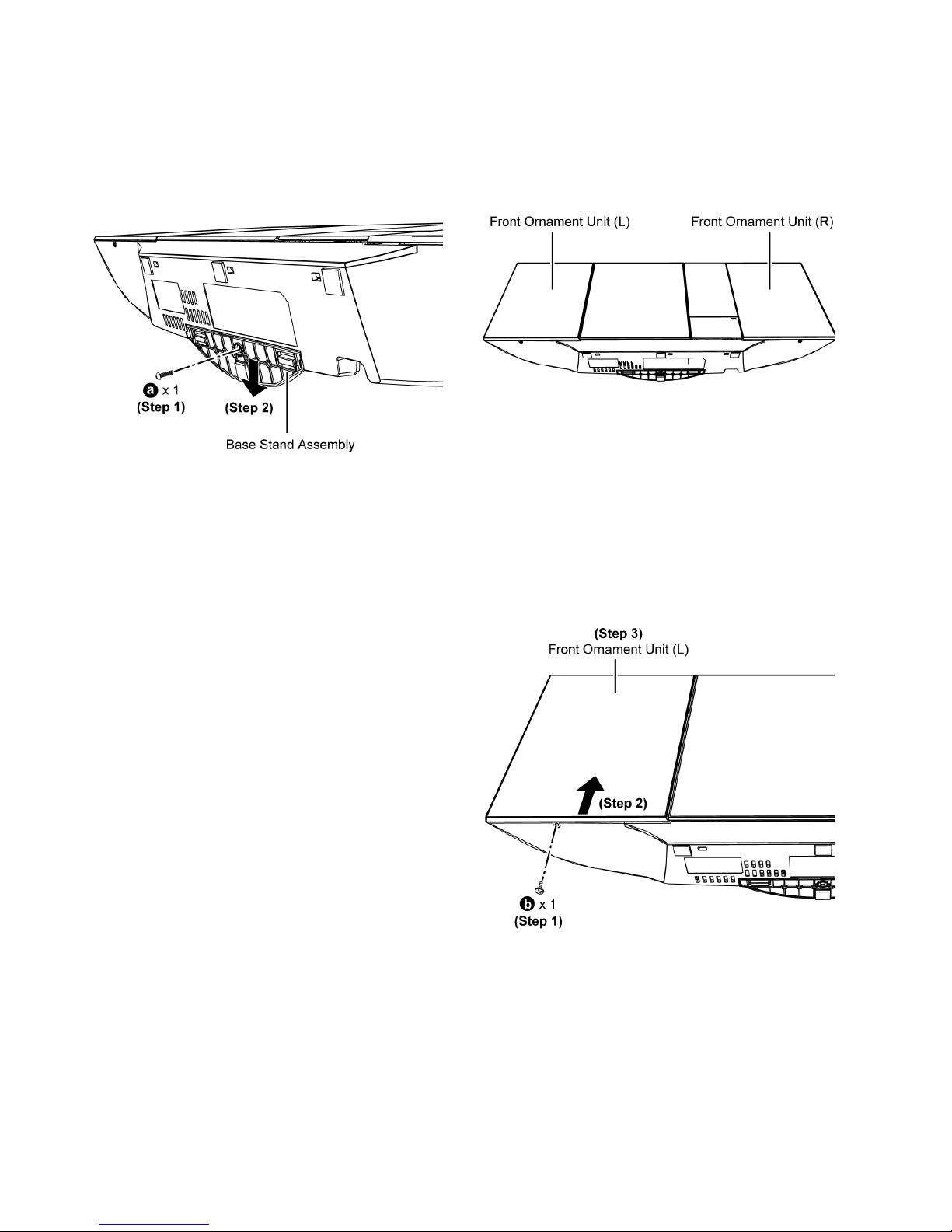
8.5. Disassembly of Base Stand
Assembly
Step 1 : Remove 1 screw.
Step 2 : Remove Base Stand Assembly.
8.6. Disassembly of Front Ornament Unit (L) & (R)
Note : The disassembling procedure for Front Ornament Unit
(L) will be described here only.
For Front Ornament Unit (R) please refer to the same procedure described here.
Step 1 : Remove 1 screw.
Step 2 : Push Front Ornament Unit (L) upwards.
Step 3 : Remove Front Ornament Unit (L).
21
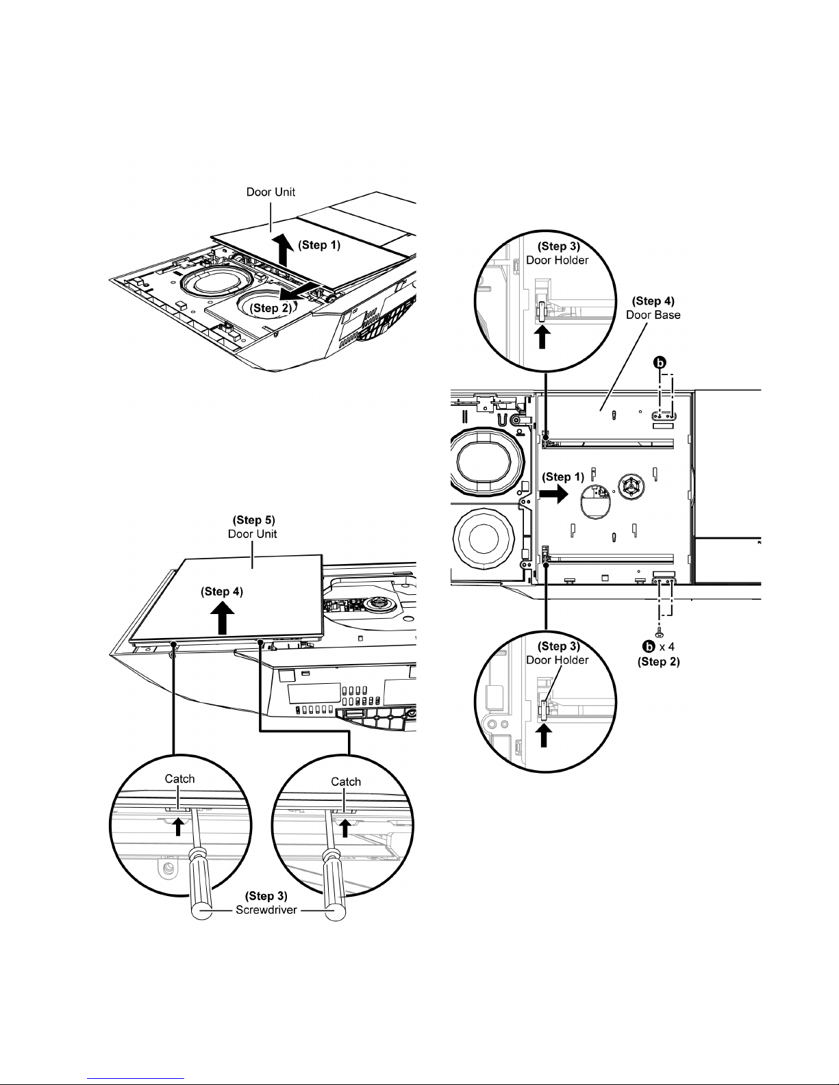
8.7. Disassembly of Door Unit
• Refer to “Disassembly of Front Ornament Unit (L)”
Step 1 : Lift up the Door Unit.
Step 2 : Slide the Door Unit to open it.
Step 3 : Slightly lift up the Door Unit as arrow shown to release
catches.
Step 4 : Push Door Unit upwards.
Step 5 : Remove Door Unit.
8.8. Disassembly of Door Base
• Refer to “Disassembly of Front Ornament Unit (L)”
• Refer to “Disassembly of Door Unit”
Step 1 : Slide the Door Base to close it.
Step 2 : Remove 4 screws.
Step 3 : Push up to release the Door Holder as arrow shown.
Caution : During assembly, ensure the Door Holder is lock
as shown.
Step 4 : Remove Door Base.

22
8.9. Disassembly of Front Panel
Block
• Refer to “Disassembly of Front Ornament Unit (L) & (R)”
Step 1 : Remove 6 screws.
Step 2 : Lift up the Door Unit.
Step 3 : Slide the Door Unit to open it.
Step 4 : Remove 2 screws.
Step 5 : Slide the Door Unit to close it.
Step 6 : Release catches on the Front Panel Block.
Step 7 : Slightly lift up the Front Panel Block.
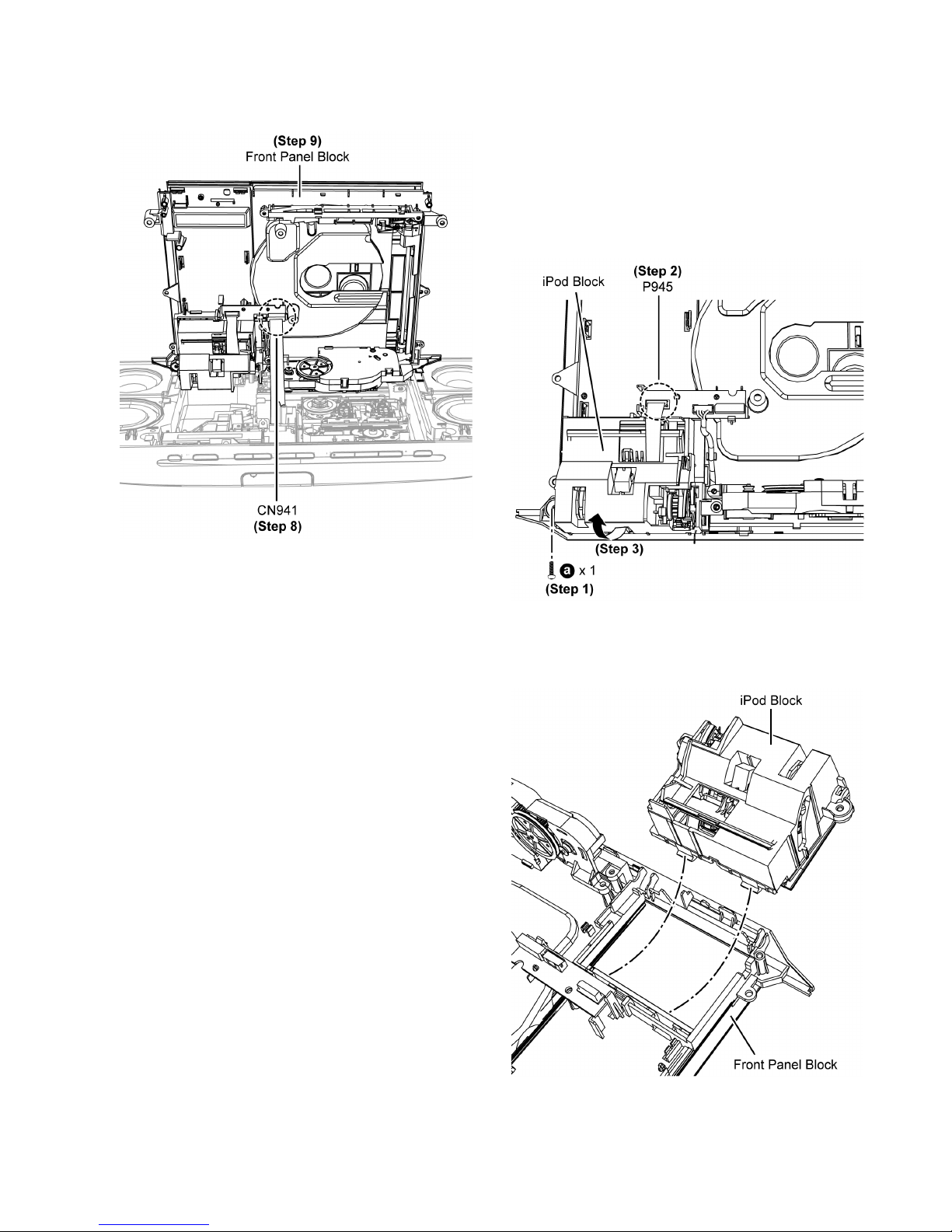
23
Step 8 : Detach 14P FFC at connector (CN941) on the Bridge
P.C.B..
Step 9 : Remove Front Panel Block.
8.10. Replacement of iPod Block
• Refer to “Disassembly of Front Ornament Unit (L) & (R)”
• Refer to “Disassembly of Front Panel Block”
8.10.1. Disassembly of iPod Block
Step 1 : Remove 1 screw.
Step 2 : Detach 9P FFC at connector (P945) on the Bridge
P.C.B..
Step 3 : Slightly lift up to remove iPod Block.
Caution : During assembling, ensure the iPod Block is
inserted into the Front Panel Block, A “tick” sound is
heard when the iPod Block is fully catched.
24
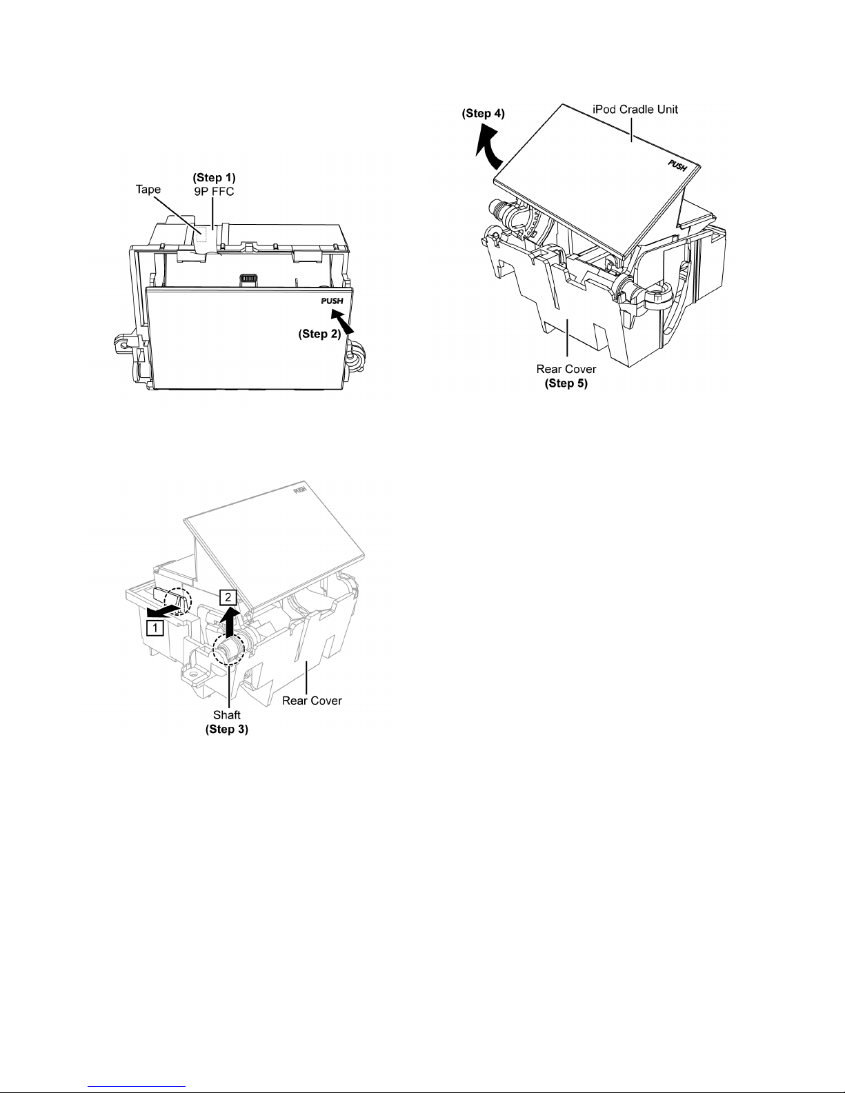
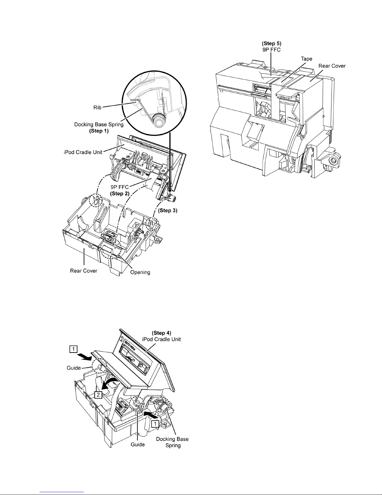
8.10.2. Disassembly of Rear Cover
• Refer to “Disassembly of iPod Block”
Step 1 : Lift up the 9P FFC.
Step 2 : Press to open the iPod Cradle Unit.
Step 3 : Pull and lift up the shaft of the iPod Cradle Unit in order
of sequences (1) to (2) as shown.
Step 4 : Lift up the iPod Cradle Unit.
Step 5 : Remove Rear Cover.
25
8.10.3. Assembly of Rear Cover
Step 1 : Place the Docking Base Spring onto the rib as shown.
Step 2 : Insert the 9P FFC into the opening of the Rear Cover.
Step 3 : Place the iPod Cradle Unit onto the Rear Cover.
Step 4 : Slightly push the guides of the iPod Cradle Unit inward
in order of sequences (1) to (2) as shown.
Caution : After assembly, Docking Ba se Spring will auto
locate to Rear Cover.
Step 5 : Paste 9P FFC on Rear Cover.
26
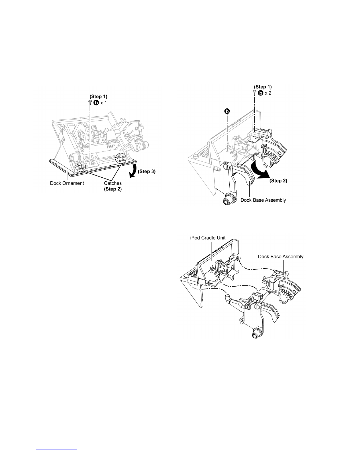
8.10.4. Disassembly of Dock Ornament
• Refer to “Disassembly of iPod Block”
• Refer to “Disassembly of Rear Cover”
Step 1 : Remove 1 screw.
Step 2 : Release catches on the Dock Ornament.
Caution : During assembling, ensure a “tack” Sound is
heard when the Dock Ornament is fully catches.
Step 3 : Remove Dock Ornament.
8.10.5. Disassembly of Dock Base Assembly & Lock Button Assembly
• Refer to “Disassembly of iPod Block”
• Refer to “Disassembly of Rear Cover”
• Refer to “Disassembly of Door Ornament”
Step 1 : Remove 2 screws.
Step 2 : Detach the Dock Base Assembly.
Caution : During assembling, ensure the Dock Base
Assembly is properly fix into the iPod Cradle Unit.
27
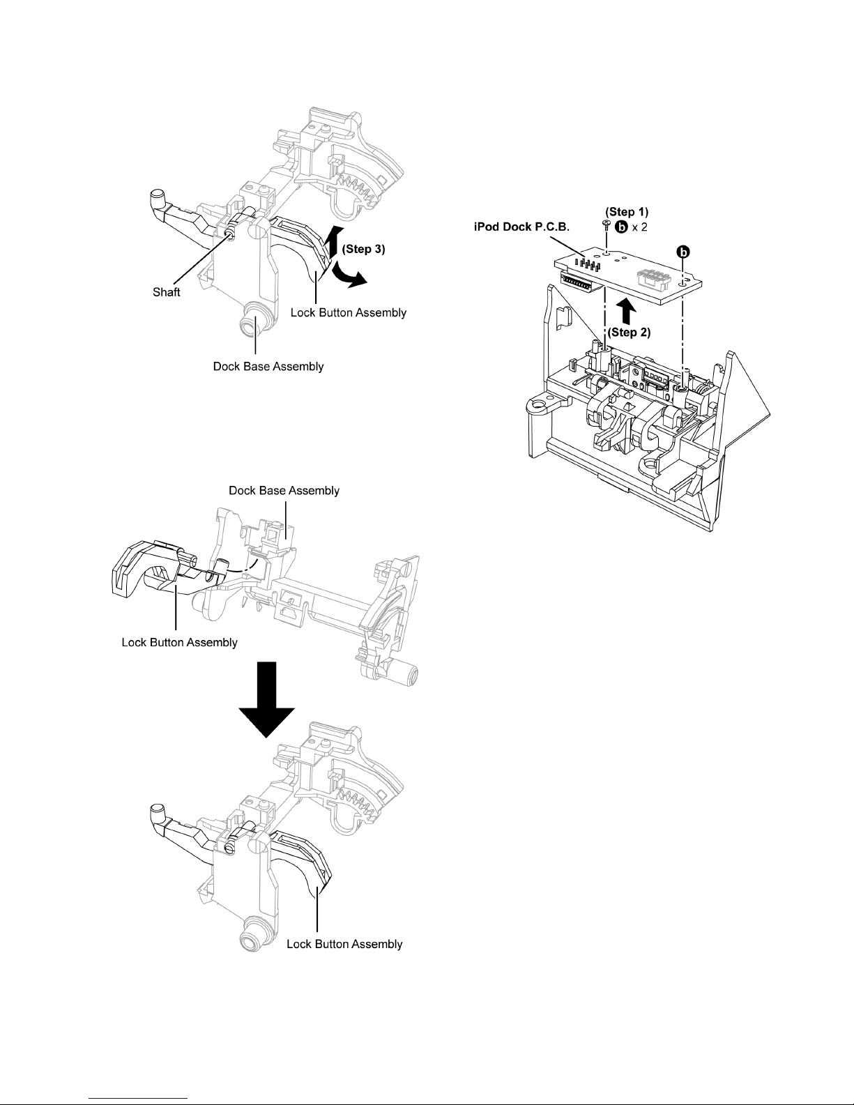
Step 3 : Lift up and remove Lock Button Assembly & Dock
Base Assembly.
Caution : During assembling, ensure the Lock Button
Assembly is properly fix into the Dock Base Assembly as
shown.
8.10.6. Disassembly of iPod Dock P.C.B.
• Refer to “Disassembly of iPod Block”
• Refer to “Disassembly of Rear Cover”
• Refer to “Disassembly of Door Ornament”
• Refer to “(Step 1) - (Step 2) of item 8.10.5.”
Step 1 : Remove 2 screws.
Step 2 : Remove iPod Dock P.C.B..
28
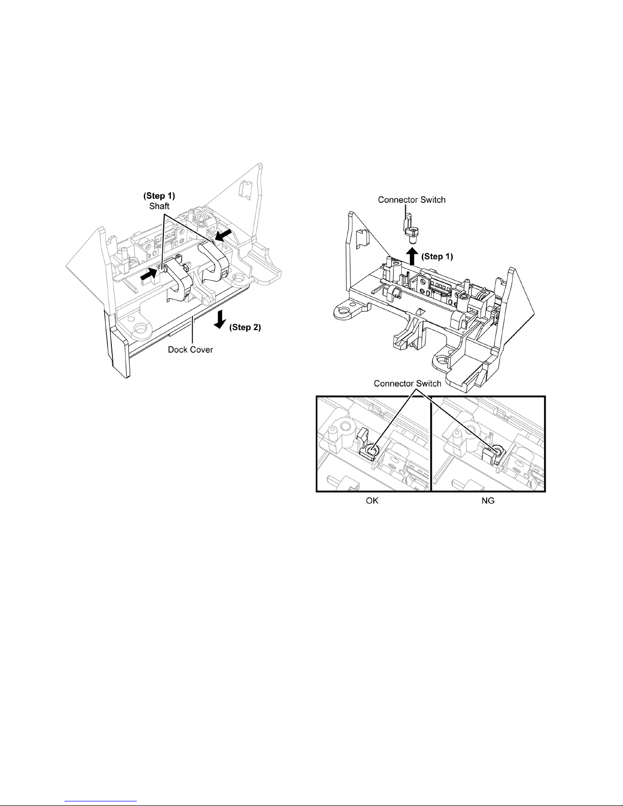
8.10.7. Disassembly of Dock Cover
• Refer to “Disassembly of iPod Block”
• Refer to “Disassembly of Rear Cover”
• Refer to “Disassembly of Dock Ornament”
• Refer to “(Step 1) - (Step 2) of item 8.10.5.”
• Refer to “Disassembly of iPod Dock P.C.B.”
Step 1 : Push the shaft of the Dock Cover inwards as shown.
Step 2 : Remove Dock Cover.
8.10.8. Disassembly of iPod Connector
Unit & iPod Cradle
• Refer to “Disassembly of iPod Block”
• Refer to “Disassembly of Rear Cover”
• Refer to “Disassembly of Door Ornament”
• Refer to “(Step 1) - (Step 2) of item 8.10.5.”
• Refer to “Disassembly of iPod Dock P.C.B.”
• Refer to “Disassembly of Dock Cover”
Step 1 : Remove Connector Switch.
Caution : During assembling, ensure the Connector Switch
is insert as shown.
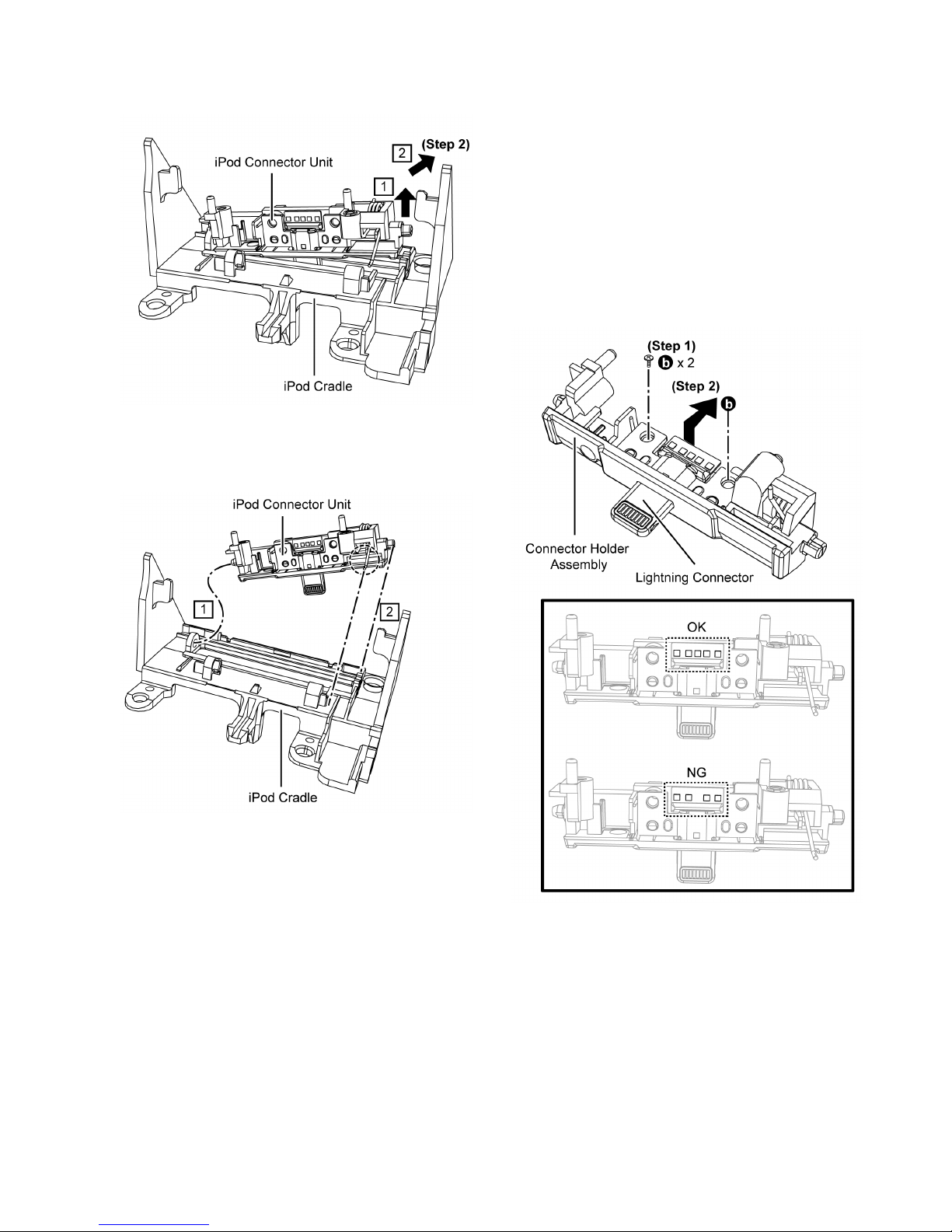
29
Step 2 : Lift up to remove iPod Connector Unit as arrown
shown in order of sequences (1) to (2).
Caution : During assembling, ensure the iPod Co nnector
Unit is properly fix into the iPod Cradle in order of
sequences (1) to (2) as shown.
8.10.9. Disassembly of Lightning Connector & Connector Holder Assembly
• Refer to “Disassembly of iPod Block”
• Refer to “Disassembly of Rear Cover”
• Refer to “Disassembly of Door Ornament”
• Refer to “(Step 1) - (Step 2) of item 8.10.5.”
• Refer to “Disassembly of iPod Dock P.C.B.”
• Refer to “Disassembly of Dock Cover”
• Refer to “Disassembly of iPod Connector Unit”
Step 1 : Remove 2 screws.
Step 2 : Remove Lightning Connector.
Caution : During assembling, ensure the lighting connec-
tor is insert properly, see picture below.
30
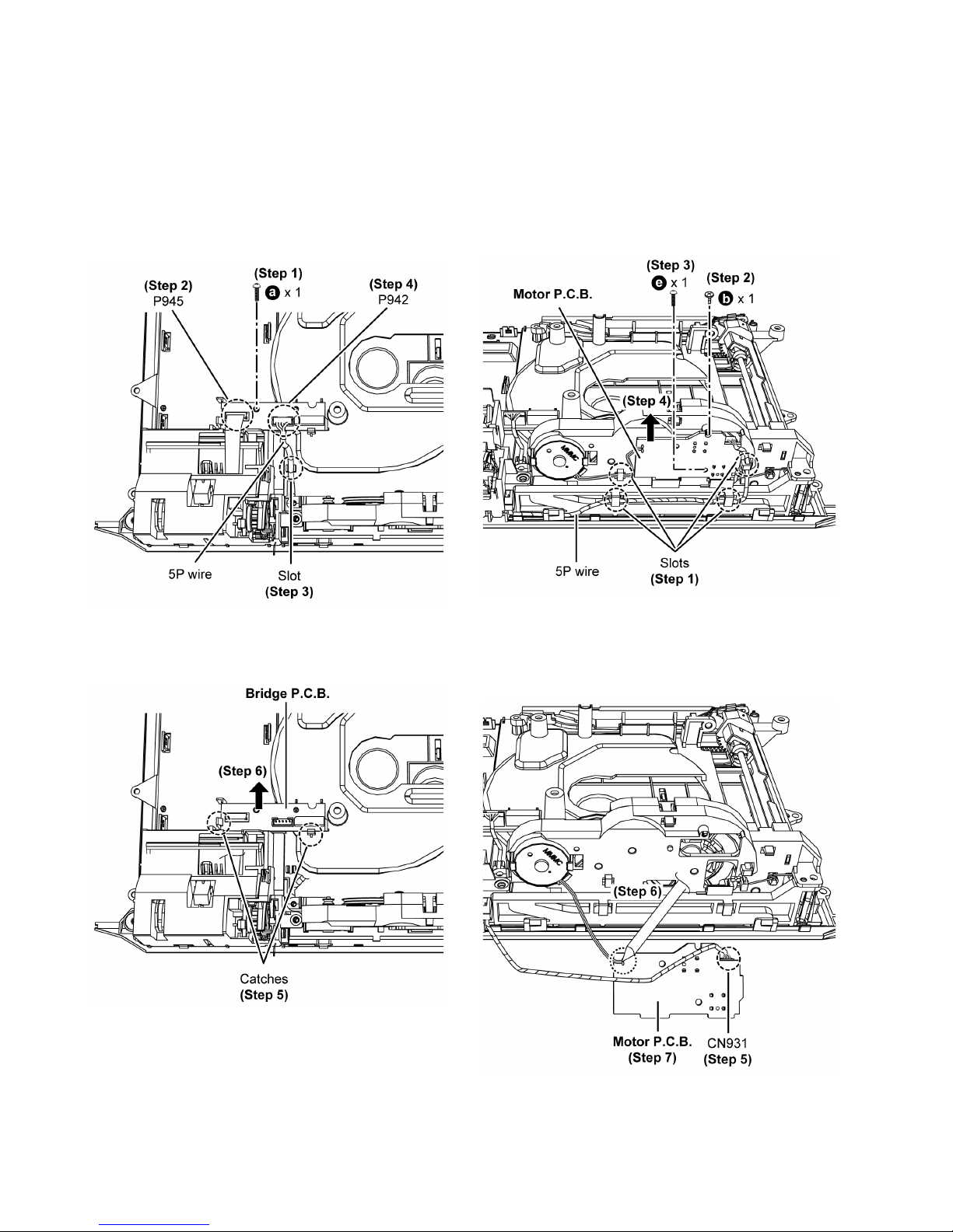
8.11. Disassembly of Bridge P.C.B.
• Refer to “Disassembly of Front Ornament Unit (L) & (R)”
• Refer to “Disassembly of Front Panel Block”
Step 1 : Remove 1 screw.
Step 2 : Detach 9P FFC at connector (P945) on the Bridge
P.C.B..
Step 3 : Release 5P wire from the slot.
Step 4 : Detach 5P wire at connector (P942) on the Bridge
P.C.B..
Step 5 : Release catches.
Step 6 : Remove Bridge P.C.B..
8.12. Disassembly of Motor P.C.B.
• Refer to “Disassembly of Front Ornament Unit (L) & (R)”
• Refer to “Disassembly of Front Panel Block”
Step 1 : Release 5P wire from the slots.
Step 2 : Remove 1 screw.
Step 3 : Remove 1 screw.
Step 4 : Lift up the Motor P.C.B..
Caution : During assembly, use manual screwing to pre-
vent overrun for [e] type screw.
Step 5 : Detach 5P wire at connector (CN931) on the Motor
P.C.B..
Step 6 : Desolder pins on the solder side of the Motor P.C.B..
Step 7 : Remove Motor P.C.B..
 Loading...