

Page 1
Operating Instructions
Manuel d’utilisation
Speaker System
Enceintes acoustiques
Model No. / Modèle SB-TP1000
Before connecting, operating or adjusting this product, please read
the instructions completely.
Please keep this manual for future reference.
Contents
Supplied accessories . . . . . . . . . . . . . . . . . . . . . . . 2
IMPORTANT SAFETY INSTRUCTIONS . . . . . . . . . 4
Location . . . . . . . . . . . . . . . . . . . . . . . . . . . . . . . . . . 5
Assembly and Installation . . . . . . . . . . . . . . . . . . . 6
Assembling the front speakers as stand types . . . . . . . 6
Assembling the surround speakers as stand types . . . 8
Wall-mounting the front and surround speakers . . . . . 10
Connections . . . . . . . . . . . . . . . . . . . . . . . . . . . . . 11
Front and surround speakers . . . . . . . . . . . . . . . . . . . . 11
Subwoofer . . . . . . . . . . . . . . . . . . . . . . . . . . . . . . . . . . 11
Bi-wiring connections . . . . . . . . . . . . . . . . . . . . . . . . . . 11
Subwoofer operation . . . . . . . . . . . . . . . . . . . . . . 12
Notes . . . . . . . . . . . . . . . . . . . . . . . . . . . . . . . . . . . 13
Warranty (U.S.A.) . . . . . . . . . . . . . . . . . . . . . . . . . . 14
Warranty (CANADA) . . . . . . . . . . . . . . . . . . . . . . . 15
Product service . . . . . . . . . . . . . . . . . . . . . . . . . . . 15
Specifications . . . . . . . . . . . . . . . . . . . . Back cover
Maintenance . . . . . . . . . . . . . . . . . . . . . Back cover
PP
Avant de raccorder, régler ou utiliser l’appareil, il est recommandé de
lire attentivement le manuel d’utilisation.
Conserver ce manuel.
Table des matières
Accessoires fournis . . . . . . . . . . . . . . . . . . . . . . . . 2
PRÉCAUTIONS À PRENDRE . . . . . . . . . . . . . . . . . 4
Emplacement . . . . . . . . . . . . . . . . . . . . . . . . . . . . . . 5
Assemblage et installation . . . . . . . . . . . . . . . . . . . 7
Assemblage des enceintes avant sur socle . . . . . . . . . 7
Assemblage des enceintes ambiophoniques
sur socle . . . . . . . . . . . . . . . . . . . . . . . . . . . . . . . . . . . . 9
Montage au mur des enceintes avant et
ambiophoniques . . . . . . . . . . . . . . . . . . . . . . . . . . . . . 10
Raccordements . . . . . . . . . . . . . . . . . . . . . . . . . . . 11
Enceintes avant et ambiophoniques . . . . . . . . . . . . . . . 11
Enceinte d’extrêmes-graves . . . . . . . . . . . . . . . . . . . . .11
Connexions bifilaires . . . . . . . . . . . . . . . . . . . . . . . . . . 11
Fonctionnement de l’enceinte
d’extrêmes-graves . . . . . . . . . . . . . . . . . . . . . . . 12
Remarques . . . . . . . . . . . . . . . . . . . . . . . . . . . . . . . 13
Garantie (CANADA) . . . . . . . . . . . . . . . . . . . . . . . . 15
Service après-vente . . . . . . . . . . . . . . . . . . . . . . . 15
Données techniques . . . . . . . . . Couverture arrière
Entretien . . . . . . . . . . . . . . . . . . . Couverture arrière
RQT8808-Y
Page 2
Dear customer
Cher client
Thank you for purchasing this product.
For optimum performance and safety, please read these instructions
carefully.
Speaker system Speaker
SB-FS1000 Front speaker (including center channel) R
SB-WA102 Active subwoofer SB-WA102 X 2
Front speaker (including center channel) L
SB-FC1000L X 1
SB-FC1000R X 1
Surround speakers SB-HS1000 X 2
User memo:
DATE OF PURCHASE
DEALER NAME
DEALER ADDRESS
TELEPHONE NUMBER
The model number and serial number of this product can be found
on either the back or the bottom of the unit.
Please note them in the space provided below and keep for future reference.
MODEL NUMBER SERIAL NUMBER
SB-FC1000L
SB-FC1000R
SB-HS1000
SB-WA102
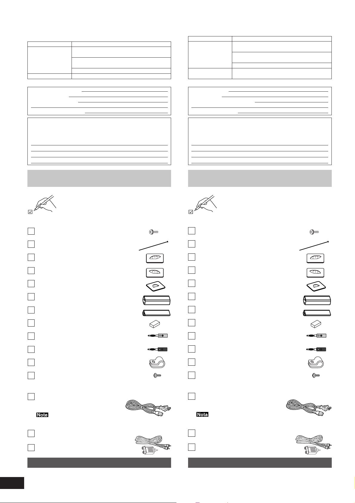
Supplied accessories
Please check and identify the supplied accessories.
Use numbers indicated in parentheses when asking for replacement parts. “As of August 2006”
In U.S.A. to order accessories, refer to “Accessory Purchases” on page 14.
SB-FS1000
Stand base mounting screws . . . . . . . . . . . . . 8
(XSB4+20FJK)
Stand mounting screws . . . . . . . . . . . . . . . . . 4
(RXQ1497)
Front L stand base . . . . . . . . . . . . . . . . . . . . . 1
(RYQ0607-K)
Front R stand base . . . . . . . . . . . . . . . . . . . . . 1
(RYQ0607A-K)
Surround stand bases . . . . . . . . . . . . . . . . . . 2
(RYQ0608-K)
Front speaker stands . . . . . . . . . . . . . . . . . . . 2
(RYQ0609A-K)
Surround speaker stands . . . . . . . . . . . . . . . . 2
(RYQ0610A-K)
Spacers . . . . . . . . . . . . . . . . . . . . . . . . . . . . 16
(RKA0191-K)
Banana plugs (red) . . . . . . . . . . . . . . . . . . . . . 6
(RJR0242-1)
Banana plugs (black) . . . . . . . . . . . . . . . . . . . 6
(RJR0242-2)
Nylon clamp . . . . . . . . . . . . . . . . . . . . . . . . . . 6
(RMR1503-K)
Screw for nylon clamp . . . . . . . . . . . . . . . . . . 6
(XTW3+10JFK)
SB-WA102
AC power supply cords . . . . . . . . . . . . . . . . . . 2
(K2CB2CB00018)
Nous vous remercions d’avoir arrêté votre choix sur cet appareil.
Pour en tirer un rendement optimal, lire attentivement le présent manuel.
Modèle Enceinte
SB-FS1000 Enceinte avant (y compris le canal central) D
SB-WA102
Enceinte avant (y compris le canal central) G
Enceinte ambiophonique droite
Enceinte d’extrêmes-graves avec
amplificateur SB-WA102 X 2
SB-FC1000L X 1
SB-FC1000R X 1
SB-HS1000 X 2
Homologation:
DATE D’ACHAT
DÉTAILLANT
ADRESSE DU DÉTAILLANT
NO DE TÉLÉPHONE
Il est recommandé de noter, dans l’espace prévu ci-dessous, le numéro
de modèle et le numéro de série inscrits à l’arrière, ou sous le fond de
l’appareil, et de conserver ce manuel pour référence ultérieure.
NUMÉRO DE MODÈLE NUMÉRO DE SÉRIE
SB-FC1000L
SB-FC1000R
SB-HS1000
SB-WA102
Accessoires fournis
Vérifier la présence et l’état des pièces et
accessoires suivants.
Lors de la commande de pièces de rechange,
utiliser les numéros indiqués entre parenthèses.
“À partir d’août 2006”
SB-FS1000
Vis de fixation de la base du socle . . . . . . . . . 8
(XSB4+20FJK)
Vis de fixation du socle . . . . . . . . . . . . . . . . . . 4
(RXQ1497)
Base du socle pour enceinte avant G . . . . . . . 1
(RYQ0607-K)
Base du socle pour enceinte avant D . . . . . . . 1
(RYQ0607A-K)
Bases des socles pour enceintes ambiophoniques
(RYQ0608-K)
Socles des enceintes avant . . . . . . . . . . . . . . 2
(RYQ0609A-K)
Socles des enceintes ambiophoniques . . . . . 2
(RYQ0610A-K)
Entretoises . . . . . . . . . . . . . . . . . . . . . . . . . . 16
(RKA0191-K)
Fiches bananas (rouge) . . . . . . . . . . . . . . . . . 6
(RJR0242-1)
Fiches bananas (noire) . . . . . . . . . . . . . . . . . . 6
(RJR0242-2)
Collier en nylon . . . . . . . . . . . . . . . . . . . . . . . . 6
(RMR1503-K)
Vis pour collier en nylon . . . . . . . . . . . . . . . . . 6
(XTW3+10JFK)
SB-WA102
Cordons d’alimentation . . . . . . . . . . . . . . . . . . 2
(K2CB2CB00018)
2
2
RQT8808
The included AC power supply cord is for use with this unit only.
Do not use it with other equipment.
Monaural connection cable (5 m) (16.4 ft) . . . 2
(RJLV1P002B50)
RCA Splitter . . . . . . . . . . . . . . . . . . . . . . . . . . 1
(RJR0243)
Speaker cables
This unit does not come with speaker cables. Have the following
speaker cables ready before proceeding with installation.
•Speaker cables (approx. 4 m) (13.1 ft) x 4
•Speaker cables (approx. 10 m) (32.8 ft) x 2
Les cordons d’alimentation fournis sont pour utilisation exclusive
avec cet appareil. Ne pas les utiliser avec un autre appareil.
Câble de raccordement monaural (5 m) (16,4 pi) . . .
(RJLV1P002B50)
Séparateur RCA . . . . . . . . . . . . . . . . . . . . . . . 1
(RJR0243)
2
Câbles d’enceintes
Les câbles d’enceintes sont vendus séparément. Avoir les câbles
suivants sous la main avant de procéder à l’installation.
•Câbles d’enceintes (env. 4 m) (13,1 pi) x 4
•Câbles d’enceintes (env. 10 m) (32,8 pi) x 2
Page 3
WARNING:
TO REDUCE THE RISK OF FIRE, ELECTRIC
SHOCK OR PRODUCT DAMAGE, DO NOT
EXPOSE THIS APPARATUS TO RAIN,
MOISTURE, DRIPPING OR SPLASHING AND
THAT NO OBJECTS FILLED WITH LIQUIDS,
SUCH AS VASES, SHALL BE PLACED ON THE
APPARATUS.
CAUTION!
DO NOT INSTALL OR PLACE THIS UNIT IN A
BOOKCASE, BUILT-IN CABINET OR IN
ANOTHER CONFINED SPACE. ENSURE THE
UNIT IS WELL VENTILATED. TO PREVENT
RISK OF ELECTRIC SHOCK OR FIRE HAZARD
DUE TO OVERHEATING, ENSURE THAT
CURTAINS AND ANY OTHER MATERIALS DO
NOT OBSTRUCT THE VENTILATION VENTS.
Although the AC power switch is in the “OFF” position, the unit is
not completely disconnected from the mains. Remove the plug
from the main electrical outlet if you will not be using the unit for
an extended period of time. Place the unit so the plug can be
easily removed.
The socket outlet shall be installed near the equipment and easily
accessible.
The mains plug of the power supply cord shall remain readily
operable.
To completely disconnect this apparatus from the AC Mains,
disconnect the power supply cord plug from AC receptacle.
CAUTION
MISE EN GARDE:
AFIN DE PRÉVENIR TOUT RISQUE D’INCENDIE
OU DE CHOCS ÉLECTRIQUES, AINSI QUE
TOUT DOMMAGE À L’APPAREIL, NE PAS
L’EXPOSER À LA PLUIE, À DES
ÉCLABOUSSURES OU À UNE HUMIDITÉ
EXCESSIVE. ÉVITER ÉGALEMENT DE PLACER
DES CONTENANTS AVEC DU LIQUIDE, TEL UN
VASE, SUR L’APPAREIL.
ATTENTION!
NE PAS INSTALLER CET APPAREIL DANS UNE
BIBLIOTHÈQUE, UNE ARMOIRE OU TOUT
AUTRE ESPACE CONFINÉ. S’ASSURER QUE
LA VENTILATION DE L’APPAREIL EST
ADÉQUATE. AFIN D’ÉVITER TOUT RISQUE DE
CHOC ÉLECTRIQUE OU D’INCENDIE DÛ À UN
SURCHAUFFEMENT, S’ASSURER QUE
RIDEAUX OU TOUT OBJET QUELCONQUE NE
BOUCHENT LES ÉVENTS D’AÉRATION DE
L’APPAREIL.
Même si l’interrupteur est à la position “OFF”, l’appareil n’est pas
entièrement déconnecté de la source d’alimentation. Débrancher
la fiche de la prise secteur si l’appareil ne sera pas utilisé pendant
une période prolongée. Placer l’appareil de façon que la fiche soit
facilement accessible.
La prise de courant doit se trouver prêt de l’appareil et être
La prise de courant doit se trouver près de l’appareil et être
facilement accessible. La fiche du cordon d’alimentation doit
facilement accessible. La fiche du cordon d’alimentation doit
demeurer à portée de la main. Pour déconnecter complètement
demeurer à portée de la main. Pour déconnecter complètement
cet appareil de sa source d’alimentation, débranchez de la prise
cet appareil de sa source d’alimentation, débranchez de la prise
de courant la fiche du cordon d’alimentation.
de courant la fiche du cordon d’alimentation.
RISK OF ELECTRIC SHOCK
DO NOT OPEN
CAUTION: TO REDUCE THE RISK OF ELECTRIC
SHOCK, DO NOT REMOVE SCREWS.
NO USER-SERVICEABLE PARTS
INSIDE.
REFER SERVICING TO QUALIFIED
SERVICE PERSONNEL.
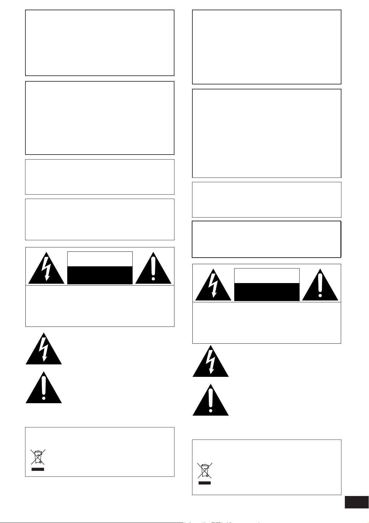
The lightning flash with arrowhead symbol, within
an equilateral triangle, is intended to alert the user
to the presence of uninsulated “dangerous voltage”
within the product’s enclosure that may be of sufficient magnitude to constitute a risk of electric shock
to persons.
The exclamation point within an equilateral triangle
is intended to alert the user to the presence of
important operating and maintenance (servicing)
instructions in the literature accompanying the
appliance.
-If you see this symbol-
Information on Disposal in other Countries outside the European Union
This symbol is only valid in the European Union.
If you wish to discard this product, please contact your
local authorities or dealer and ask for the correct method
of disposal.
ATTENTION
RISQUE DE CHOC ELECTRIQUE
NE PAS OUVRIR
ATTENTION: AFIN DE PRÉVENIR LE RISQUE
DE CHOCS ÉLECTRIQUES, NE
PAS RETIRER LES VIS.
TOUTE RÉPARATION DEVRAIT
ÊTRE CONFIÉE À UN
PERSONNEL QUALIFIÉ.
Le symbole de l’éclair dans un triangle équilatéral
indique la présence d’une tension suffisamment
élevée pour engendrer un risque de chocs
électriques.
Le point d’exclamation dans un triangle équilatéral
indique que le manuel d’utilisation inclus avec
l’appareil contient d’importantes recommandations
quant au fonctionnement et à l’entretien de ce
dernier.
- Si ce symbole apparaît -
Information sur la mise au rebut dans les pays n'appartenant
pas à l'Union européenne
Ce symbole est uniquement valide dans l'Union
européenne.
Si vous désirez mettre ce produit au rebut, contactez
l'administration locale ou le revendeur et informez-vous
de la bonne façon de procéder.
3
RQT8808
Page 4
IMPORTANT SAFETY
PRÉCAUTIONS À
INSTRUCTIONS
Read these operating instructions carefully before using the unit. Follow the safety instructions on the unit and the applicable safety instructions listed below. Keep these operating instructions handy for
future reference.
1) Read these instructions.
2) Keep these instructions.
3) Heed all warnings.
4) Follow all instructions.
5) Do not use this apparatus near water.
6) Clean only with dry cloth.
7) Do not block any ventilation openings. Install in accordance with
the manufacturer’s instructions.
8) Do not install near any heat sources such as radiators, heat registers, stoves, or other apparatus (including amplifiers) that produce heat.
9) Do not defeat the safety purpose of the polarized or groundingtype plug. A polarized plug has two blades with one wider than
the other. A grounding-type plug has two blades and a third
grounding prong. The wide blade or the third prong are provided
for your safety. If the provided plug does not fit into your outlet,
consult an electrician for replacement of the obsolete outlet.
PRENDRE
Avant d’utiliser l’appareil, lire attentivement le présent manuel. Porter
une attention toute particulière aux avis inscrits sur l’appareil et aux
instructions décrites ci-dessous. Conserver ce manuel pour
référence ultérieure.
1) Lire ces instructions.
2) Conserver ces instructions.
3) Respecter toutes les mises en garde.
4) Suivre toutes les instructions.
5) Ne pas utiliser cet appareil près de l’eau.
6) Nettoyer avec un chiffon sec seulement.
7) Ne pas bloquer les ouvertures pour ventilation. Installer selon
les directives du fabricant.
8) Éloigner l’appareil de toute source de chaleur telle que radiateurs et autres éléments de chauffage (incluant les amplificateurs).
9) Ne pas tenter de contourner les mesures de sécurité des fiches
polarisées ou de mise à la terre. Une fiche polarisée possède
une lame plus large que l’autre. Une fiche avec mise à la terre
possède une troisième broche pour la mise à la terre. Si la fiche
ne peut pas être branchée, communiquer avec un électricien
pour faire changer la prise de courant.
10) Protect the power cord from being walked on or pinched particularly at plugs, convenience receptacles, and the point where
they exit from the apparatus.
11) Only use attachments/accessories specified by the manufacturer.
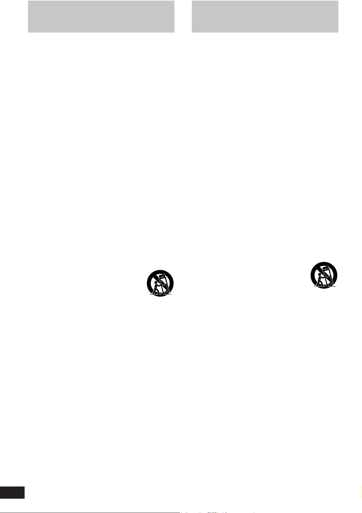
12) Use only with the cart, stand, tripod, bracket, or
table specified by the manufacturer, or sold with
the apparatus. When a cart is used, use caution
when moving the cart/apparatus combination to
avoid injury from tip-over.
13) Unplug this apparatus during lightning storms or when unused
for long periods of time.
14) Refer all servicing to qualified service personnel. Servicing is
required when the apparatus has been damaged in any way,
such as power-supply cord or plug is damaged, liquid has been
spilled or objects have fallen into the apparatus, the apparatus
has been exposed to rain or moisture, does not operate normally, or has been dropped.
10) Protéger le cordon d'alimentation de manière qu’il ne soit pas
piétiné ou écrasé par des objets. Faire particulièrement attention à ses extrémités de branchement, y compris sa fiche.
11) N’utiliser que les accessoires recommandés par le fabricant.
12) Ne placer l’appareil que dans une baie ou un
support recommandé par le fabricant. Déplacer
la baie ou le support avec le plus grand soin afin
d’en éviter le renversement.
13) Débrancher durant un orage ou lors de non-utilisation prolongée.
14) Confier toute réparation à un technicien qualifié. Faire réparer
l’appareil si le cordon ou la fiche a été endommagé, si l’appareil
a été mouillé, si un objet est tombé sur l’appareil, s’il a été exposé à la pluie ou à de l’humidité, s’il ne fonctionne pas normalement ou s’il a été échappé.
4
RQT8808
Page 5
30°
30°
120°
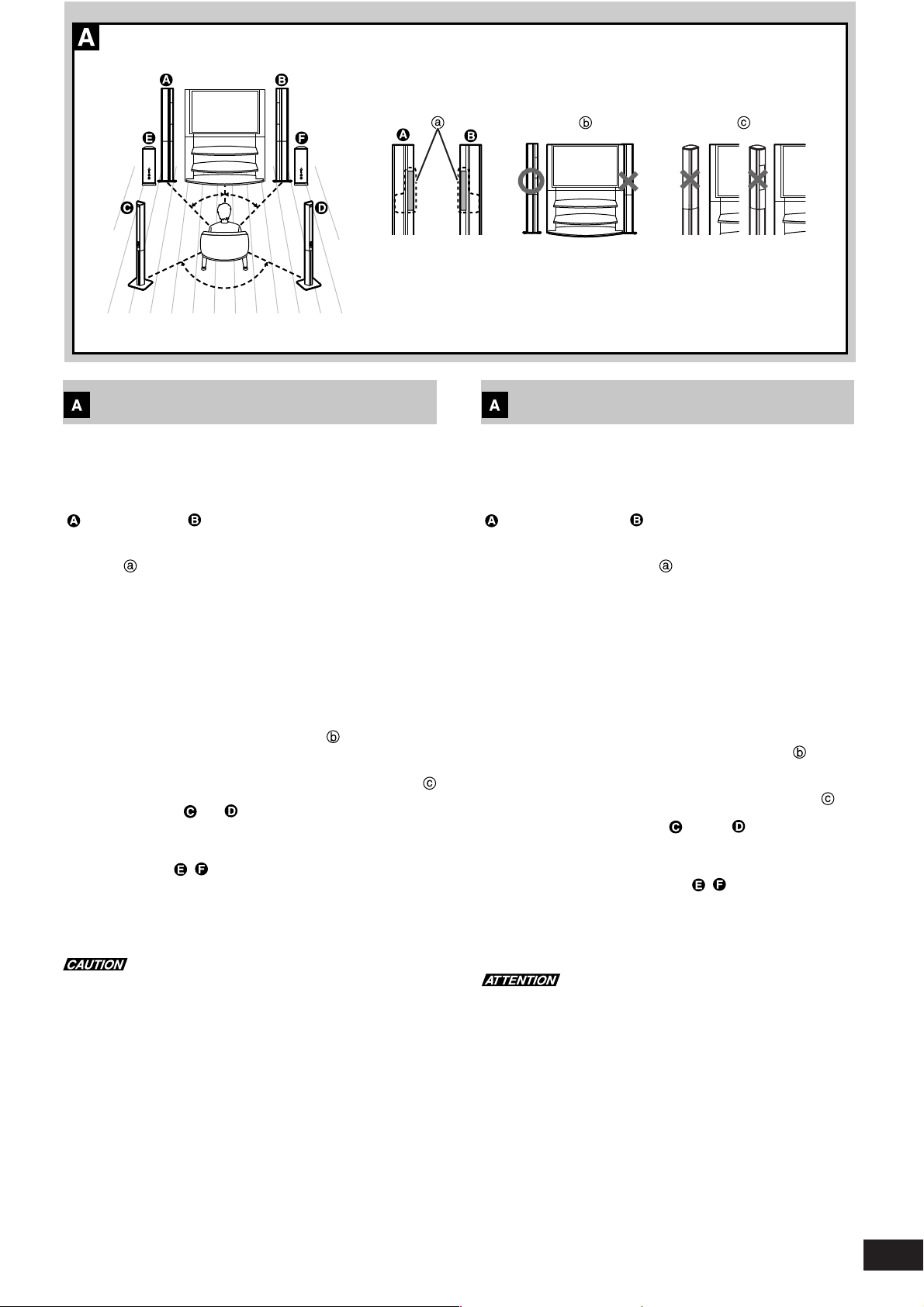
Location
The front and surround speakers should be placed at approximately
the same distance from the listening position. The angles in the diagram are approximate.
Front speakers (including center channel)
( left: SB-FC1000L, right: SB-FC1000R)
•Put the front speakers on either side of the television.
This system incorporates a center speaker in each of its front
speakers.
Using a unique system from Panasonic that reflects the principles of
auditory psychology, the sound seems to come from within the TV
screen, letting you enjoy sound and images with a heightened sense
of integration even if you are not seated directly in front of the TV set.
•It may be hard for the intended effect to be achieved under some
listening and viewing conditions and with some of the playback
sources.
•The effect will not be satisfactorily yielded if the left front speaker
is installed on the right and the right front speaker on the left.
•The sound quality will not be satisfactorily yielded if the center
speakers are hidden from the listener’s view.
•Do not position the front speakers so that they face outward or
overly inward.
Place them so that they are facing more or less straight ahead.
Surround speakers ( left, right: SB-HS1000)
•Put the surround speakers to the side of or slightly behind the seating area.
Active subwoofer ( , : SB-WA102)
•Place it at least 5 cm (2˝) from the wall as it has a bass reflex port in
the rear.
•Depending on speaker location, the low-range frequency characteristics will vary. When placed in the corner of a room, the volume will
increase accordingly.
Do not attach the subwoofer to walls or ceilings.
How you set up your speakers can affect the bass and the sound
field. Note the following points.
•Place them on a flat, level secure surface.
Use spacers or similar items to stop them from rocking.
•Placing speakers too close to walls, and corners can result in excessive bass.
•Cover walls and windows with a thick curtain.
•Do not place anything on top of the subwoofer.
Emplacement
Positionner les enceintes ambiophoniques avant et arrière à une
distance égale de la position d’écoute. Les angles illustrés dans le
schéma sont approximatifs.
Enceintes avant (y compris le canal central)
( gauche: SB-FC1000L, droite: SB-FC1000R)
•Positionner les enceintes avant de chaque côté du téléviseur.
Ce système incorpore un haut-parleur de canal central dans
chacune des enceintes avant.
Grâce à un système unique de Panasonic qui reflète les principes de
la psychologie auditive, le son semble provenir de l’intérieur de l’écran
du téléviseur, ce qui vous permet de profiter du son et de l’image avec
un sens rehaussé d’immersion même si vous n’êtes pas assis
directement devant le téléviseur.
•Il peut être difficile d’accomplir l’effet désiré sous certaines conditions de visionnement et d’écoute ainsi qu’avec certaines sources
de lecture.
•L’effet laissera à désirer si l’enceinte gauche est placée sur le côté
droit et l’enceinte droite sur le côté gauche.
•La qualité du rendu sonore ne sera pas optimale si les enceintes
centrales ne sont pas visibles de la position d’écoute.
•Ne pas placer les enceintes avant de façon à ce qu’elles soient
positionnées vers l’intérieur ou l’extérieur. Les placer de façon à
ce qu’elles soient positionnées plus ou moins droit devant.
Enceinte ambiophonique droite ( gauche, droite: SB-HS1000)
•Placer les enceintes ambiophoniques de chaque côté de la position
d’écoute ou légèrement derrière.
Enceinte d’extrêmes-graves active ( , : SB-WA102)
•La placer à une distance d’au moins 5 cm (2 po) du mur en raison
de la présence d’un évent acoustique à l’arrière.
•Les caractéristiques des fréquences de la limite inférieure varient
selon la position de l’enceinte. Si elle est placée dans un coin, le
volume augmente.
Ne pas fixer l’enceinte d’extrêmes-graves à un mur ou la suspendre
au plafond.
L’emplacement des enceintes peut affecter les graves et le champ
sonore. Lire attentivement les points suivants.
•Placer les enceintes sur une surface plate, de niveau et sécuritaire.
Utiliser des cales ou un objet similaire pour éviter qu’elles ne
basculent.
•Afin d’éviter une production excessive des graves, ne pas placer les
enceintes trop près du plancher, des murs ou des coins.
•Recouvrir les murs et les fenêtres d’un rideau épais.
•Ne rien placer sur l’enceinte d’extrêmes-graves.
5
RQT8808
Page 6

Assembly and Installation
Assembling the front speakers as stand types
R
R
6
RQT8808
•Do not apply an unreasonable force to the net at the front of the
speaker unit. You cannot remove the front net.
•You can carry out assembly work stably by placing the cushions in
the packing case beneath the speaker. Place the net sides of the
speaker units face up.
Cushions used
Speaker units.
Use the four cushions at the very top of the SB-FS1000.
Method of setting cushions
Place these surfaces face up.
Be sure to spread a cloth, for example, on the floor to protect it from
damage.
•After each task, tighten the screws securely.
1.Fit the stand bases onto the front speaker stands.
Align the two projections in one of the front speaker stands
(provided) with the two holes in the front R stand base
(provided), and fit together.
•The packing bag for the front R stand base and the packing bag
for the front center speaker R are held in place by tape of the
same color. Assemble the base and speaker with the same color
tape.
•Similarly, the packing bag for the front L stand base and the packing bag for the front center speaker L are held in place by tape of
the same color.
Attach the stand base using the two stand base mounting
screws (provided).
Use the two screw holes marked “R” to attach the base.
•Align the positions of the holes marked “R” with the positions of
the screw holes in the stand. If the positions do not line up,
change the direction of the stand. (The base can be fitted onto
the top or bottom of the stand.)
•When assembling front speaker L, use the screw holes marked
“L” and fit.
•Tighten the screws alternately, and finally tighten them hard.
Reverse side of stand base
2.Fit the stand onto front speaker R.
Align the two projections in the assembled stand with the two
holes in front speaker R , and fit together.
Attach the stand using the stand mounting screw (provided).
Use the center screw hole to fit the stand on to the speaker.
3.Connect the speaker cables (not provided) to the
terminals.
Before connection, pass the speaker cords through the hole marked
“R” in the back of the stand base.
(Use the hole marked “L” for the left front speaker.)
Speaker cables (approx. 4 m)
(–) cable :
Connect this to the “CENTER” black negative (–) terminal.
(+) cable :
Connect this to the “CENTER” red positive (+) terminal.
Speaker cables (approx. 4 m)
(–) cable :
Connect this to the “LF” black negative (–) terminal.
(+) cable :
Connect this to the “HF” red positive (+) terminal.
Do not remove the shorting bars.
Turn the thumb nut in the loosening direction until the hole
in the terminal becomes visible.
Insert the conductor into the hole, and tighten the thumb
nut.
When using banana plugs (4 mm plugs)
Loosen the screws of the banana plugs (provided).
Twist the conductors of the speaker cable.
Insert the speaker cables all the way, then firmly tighten
the screws.
Tighten the thumb nuts of the terminals all the way, and connect
the plugs.
•When using commercially available banana plugs, use banana
plugs that have an overall diameter of 10 mm or less.
Do not use the banana plugs when the speakers are to be mounted
on a wall.
Never short-circuit positive (+) and negative (–) speaker wires.
4.Fix the speaker cables.
Press the speaker cables into the cable groove provided in the stand.
The speaker cables must have a thickness of 2.8 mm or less to fit into
the cable groove.
Cable groove
When using speaker cables that are thicker than 2.8 mm, attach
nylon clampers to the speakers and use them to fix the cables.
Example Nylon clamp (provided)
Screw for nylon clamp (provided)
Speaker cables
Repeat steps 1 to 4 and assemble front speaker L.
Page 7

R
10 mm
10 mm
Assemblage et installation
Assemblage des enceintes avant sur socle
•Ne pas forcer la grille à l’avant de l’enceinte. Il est impossible de
retirer la grille.
•L’assemblage s’effectue plus facilement si les enceintes sont
déposées sur les coussinets d’emballage. Orienter la grille des
enceintes vers le haut.
Utilisation des coussinets
Enceintes
Utiliser les quatre coussinets installés sur le dessus de l’enceinte
SB-FS1000.
Mode de mise en place des coussinets
Placer ces surfaces orientées vers le haut.
S’assurer de placer les composants sur un linge doux pour prévenir
tout risque de dommage.
•Après chaque étape, serrer les vis à fond.
1.Installer les bases sur les socles des enceintes
avant.
Aligner les deux tiges en saillie de l’un des socles des
enceintes avant (fournis) avec les deux trous dans l’avant
de la base du socle de l’enceinte avant D (fourni) et les y
introduire.
•Le sac d’assemblage pour la base du socle pour enceinte avant
D et le sac d’assemblage pour la base du socle pour enceinte
avant centrale D sont retenus en place par du ruban adhésif de
la même couleur.
•
Pareillement, le sac d’assemblage pour la base du socle pour enceinte avant G et le sac d’assemblage de l’enceinte avant centrale G
sont retenus en place par du ruban adhésif de la même couleur.
Fixer la base du socle au moyen des deux vis de montage
fournies.
Introduire les vis dans les deux trous “R” pour fixer la base.
•Aligner les trous “R” avec les trous pour les vis du socle. Si les
trous ne sont pas alignés, changer l’orientation du socle. (La base
peut être placée sur le dessus ou le dessous du socle.)
•Pour l’assemblage de l’enceinte avant G, utiliser les trous de vis
“L” et fixer.
•Serrer les vis en alternance, puis les serrer à fond.
Revers de la base du socle
2.Installer le socle sur l’enceinte avant D.
Aligner les deux tiges en saillie du socle assemblé avec les
deux trous de l’enceinte avant D et les y introduire.
Fixer le socle à l’aide de la vis de montage du socle (fournie).
Fixer le socle à l’enceinte par le trou de vis du centre.
3.Raccorder les câbles d’enceintes (non fournis)
aux bornes.
Avant d’effectuer les raccordements, passer les câbles dans le
trou “R” à l’arrière de la base du socle.
(Utiliser le trou “L” pour les câbles de l’enceinte avant gauche.)
Câbles d’enceinte (env. 4 m)
(–) câble :
Raccorder ce câble à la borne négative noire (–) “CENTER”.
(+) câble :
Raccorder ce câble à la borne positive rouge (+) “CENTER”.
Câbles d’enceinte (env. 4 m)
(–) câble :
Raccorder ce câble à la borne négative (–) noire “LF”.
(+) câble :
Raccorder ce câble à la borne positive (+) rouge “HF”.
Ne pas retirer les tiges court-circuit.
Tourner l’écrou à molette dans la direction de desserrage
jusqu’à ce que le trou de la borne devienne visible.
Introduire le conducteur dans le trou, puis serrer l’écrou à
molette.
Avec des fiches bananes (fiches de 4 mm)
Desserrer les vis des fiches bananes (fournies).
Torsader les conducteurs du câble d’enceinte.
Insérer les câbles d’enceinte à fond, puis serrer fermement
les vis.
Serrer à fond les écrous à molette des bornes et connecter les fiches.
•Pour utiliser des fiches bananes en vente dans le commerce,
elles doivent avoir un diamètre total de 10 mm ou moins.
Ne pas utiliser les fiches bananes lorsque les enceintes doivent
être montées sur un mur.
Ne jamais court-circuiter les fils positif (+) et négatif (–) du câble
d’enceinte.
4.Attacher les câbles d’enceintes.
Insérer les câbles d’enceintes dans la rainure du socle prévue à
cet effet.
Les câbles d’enceinte doivent avoir une épaisseur de 2,8 mm ou moins
pour entrer dans la rainure pour câble.
Rainure pour câble
Pour utiliser des câbles d’enceinte plus épais que 2,8 mm, fixer des
attaches de nylon aux enceintes et les utiliser pour fixer les câbles.
Exemple Collier en nylon (fournie)
Vis pour collier en nylon (fournie)
Câbles d’enceintes
Recommencer les étapes 1 à 4 pour l’enceinte avant gauche.
7
RQT8808
Page 8

1
S
Assembly and Installation
2
S
Assembling the surround speakers as stand types
•Do not apply an unreasonable force to the net at the front of the
speaker unit. You cannot remove the front net.
•You can carry out assembly work stably by placing the cushions in
the packing case beneath each speaker. Place the net sides of the
speaker units face up. ( page 6) Use the same cushions as
used for the front speakers.
Be sure to spread a cloth, for example, on the floor to protect it from
damage.
•After each task, tighten the screws securely.
1.Fit the stand bases onto the surround speaker
stands.
Align the two projections in one of the surround speaker
stands (provided) with the two holes in one of the surround
stand bases (provided), and fit together.
Install the stand base at the end where the sticker has been
adhered on the inside.
Attach the stand base using the two stand base mounting
screws (provided).
Use the two screw holes marked “S” to attach the base.
Reverse side of stand base
2.Fit the stands onto the surround speakers.
Align the two projections in the assembled stand with the two
holes in the surround speaker , and fit together.
Attach the stand using the stand mounting screw (provided).
Use the center screw hole to fit the stand on to the speaker.
4.Fix the speaker cables.
Press the speaker cables into the cable groove provided in
the stand.
The speaker cables must have a thickness of 2.8 mm or less to fit
into the cable groove.
Cable groove
When using speaker cables that are thicker than 2.8 mm, attach
nylon clampers to the speakers and use them to fix the cables.
Example Nylon clamp (provided)
Screw for nylon clamp (provided)
Speaker cables
Repeat steps 1 to 4 and assemble the other surround speaker.
Attaching a stabilizing wire
Example Remove the cover Wire (not included)
Ring (not included) Screw (not included)
The wall on which the speakers are to be mounted and the screws
(not included) used for installing the speakers must be strong enough
to support a weight of at least 65 kg (143 lb.) for the front speakers
and 50 kg (110 lb.) for the surround speakers. Consult the contractor
in charge of the work.
A screw which is at least 35 mm long ( see above) is used
when installing the speaker on a wooden post or pillar. In all other
cases, use a screw which is strong enough to support a weight of at
least 65 kg (143 lb.) or 50 kg (110 lb.).
8
RQT8808
3.Connect the speaker cables (not provided) to the
terminals
Before connection, pass the speaker cords through the hole marked
“S” in the back of the stand base.
Speaker cables (approx. 10 m)
(–) cable : Connect this to the black negative (–) terminal.
(+) cable : Connect this to the red positive (+) terminal.
Never short-circuit positive (+) and negative (–) speaker wires.
Settings for connecting the recommended amplifier
to the active subwoofer
When using our SA-XR700 AV control receiver (not included)
First make the following settings.
•Refer to “Setting the Amplifier” in the instruction manual for the
SA-XR700 AV control receiver.
Setting the speaker (YES/NO) and its size
Speaker to be set Setting item
SUBW (subwoofer) YES (Connected)
LR (Front) SMALL
C (Center) SMALL
S (Surround) SMALL
Setting the lower region filter
Selection frequency: 80 (Frequencies of 80 Hz and below are
output to the subwoofer.)
Note
To improve the acoustics, it is recommended that the amplifier’s
center speaker output level be set 1 dB to 3 dB higher than usual.
Page 9

3
4
S
Assemblage et installation
Assemblage des enceintes ambiophoniques sur socle
•Ne pas forcer la grille à l’avant de l’enceinte. Il est impossible de
retirer la grille.
•L’assemblage s’effectue plus facilement si les enceintes sont
déposées sur les coussinets d’emballage. Placer les enceintes, la
grille vers le haut. ( page 7). Utiliser les mêmes coussinets
que ceux utiliser pour les enceintes avant.
S’assurer de placer les composants sur un linge doux pour prévenir
tout risque de dommage.
•Après chaque étape, serrer les vis à fond.
4.Attacher les câbles d’enceintes.
Insérer les câbles d’enceintes dans la rainure du socle prévue
à cet effet.
Les câbles d’enceinte doivent avoir une épaisseur de 2,8 mm ou
moins pour entrer dans la rainure pour câble.
Rainure pour câble
Pour utiliser des câbles d’enceinte plus épais que 2,8 mm, fixer des
attaches de nylon aux enceintes et les utiliser pour fixer les câbles.
Exemple Collier en nylon (fournie)
1.Installer les bases sur les socles des enceintes
ambiophoniques.
Aligner les deux tiges en saillie de l’un des socles (fournis)
des enceintes ambiophoniques avec les deux trous dans
l’une des bases des socles des enceintes ambiophoniques
(fournies) et les y introduire.
Installer le socle sur l’extrémité où le collant à été posé à
l’intérieur.
Fixer la base au socle au moyen des deux vis de montage
(fournies).
Introduire les vis dans les trous “S” pour fixer la base au socle.
Revers de la base du socle
2.
Installer les socles sur les enceintes ambiophoniques.
Aligner les deux tiges en saillie du socle assemblé avec les
deux trous de l’enceinte ambiophonique et les y introduire.
Fixer le socle à l’aide de la vis de montage du socle (fournie).
Fixer le socle à l’enceinte par le trou de vis du centre.
3.Raccorder les câbles d’enceintes (non fournis)
aux bornes.
Avant d’effectuer les raccordements, passer les câbles dans le trou
“S” à l’arrière de la base du socle.
Câbles d’enceinte (env. 10 m)
(–) câble : Raccorder ce câble à la borne négative (–) noire.
(+) câble : Raccorder ce câble à la borne positive (+) rouge.
Ne jamais court-circuiter les fils positif (+) et négatif (–) du câble
d’enceinte.
Recommencer les étapes 1 à 4 pour assembler l’autre enceinte
ambiophonique.
Installation d’un fil de stabilisation
Exemple Retirer le couvercle Fil (non fourni)
Le mur sur lequel les enceintes doivent être montées et les vis
(vendues séparément) utilisées pour fixer les enceintes doivent être
capables de supporter un poids d’au moins 65 kg (143 lb) dans le cas
des enceintes avant et de 50 kg (110 lb) dans le cas des enceintes
ambiophoniques. Consulter l’entrepreneur en charge des travaux.
Une vis longue d’au moins 35 mm ( voir ci-dessus) est utilisée
pour installer l’enceinte sur un montant ou pilier de bois. Dans tous
les autres cas, utiliser une vis capable de supporter un poids d’au
moins 65 kg (143 lb) ou de 50 kg (110 lb).
Réglages pour le raccordement de l’amplificateur
recommandé à l’enceinte active
Avec le récepteur de commande SA-XR700 AV (vendu séparément)
Procéder d’abord aux réglages suivants.
•Consulter “Réglage de l’amplificateur” dans le manuel d’utilisation
du récepteur de commande SA-XR700 AV.
Activation ou non de l’enceinte et réglage de sa taille
Enceinte à régler Paramètre à régler
SUBW (extrêmes-graves) YES (connectée)
LR (avant) SMALL (petite)
C (centrale) SMALL (petite)
S (ambiophonique) SMALL (petite)
Réglage du filtre passe-bas
Sélection de la fréquence: 80 (les fréquences inférieures à 80
Hz sont envoyées à l’enceinte d’extrêmes-graves).
Nota
Pour améliorer l’acoustique, il est recommandé que le niveau de
sortie de l’enceinte centrale de l’amplificateur soit réglé de 1dB à 3
dB plus élevé que d’habitude.
※
ø7.0-9.4 mm
Vis pour collier en nylon (fournie)
Câbles d’enceintes
Anneau (non fourni) Vis (non fournie)
ø4 mm
9
RQT8808
Page 10

16.5 mm
SUBWOOFER
TV/STB
FRONT A FRONT B CENTER SURROUND
SURROUND BA
Y
TV MONITOR OUT TV / STB INDVD RECORDER IN
PBP
R
SPEAKERS
COMPONENT VIDEO
HAUT-PARLEURS
YYPBPRPBP
R
AC
RLRL RLR
BI-WIRE
LF HF
IN
OUT
IN
TV/STB
(21/32˝)
(21/32 po)
35 mm
705 mm
(27-25/32˝)
(27-25/32 po)
35 mm
ø4 mm
ø7.0-9.4 mm
8-10 mm
(5/16˝ to 13/32˝)
(5/16 po à 13/32 po)
Assembly and Installation
Wall-mounting the front and surround speakers
Do not attempt to attach these speakers to walls using methods
other than those described in this manual.
•After each task, tighten the screws securely.
•Keep the removed parts carefully aside.
1.Connect the speaker cables (not provided) to the
terminals.
Refer to step 3 on page 6 and step 3 on page 8.
•If the speakers are to be wall-mounted, the stands and stand
bases need not be fitted onto the speaker units.
When mounting the speakers on a wall, use speaker cables
that have a thickness of 3.8 mm or less.
•When using speaker cables that have multiple coverings, remove
the outer coverings (leave the innermost covering) so that the
cable thickness is 3.8 mm or less for a length of 200 mm from the
connection end.
2.Adhere the spacers and mount the speakers on
the wall.
Remove the covers from the back of the speakers.
Adhere the spacers in the four locations.
•Align the spacers with the bottom of the holes used for wall mounting, and adhere.
Mount the speakers on the wall.
When the screws are in this position, the speaker may drop off.
Fit the speaker securely so the screws are in this position.
Screw (not included)
Arrange the speaker cables in such a way that they will not touch
the holes used for wall mounting.
The wall on which the speakers are to be mounted and the screws
(not included) used for installing the speakers must be strong
enough to support a weight of at least 30 kg (66 lb.) for the front
speakers and 20 kg (44 lb.) for the surround speakers. Consult the
contractor in charge of the work.
A screw which is at least 35 mm long ( see above) is used
when installing the speaker on a wooden post or pillar. In all
other cases, use a screw which is strong enough to support a
weight of at least 30 kg (66 lb.) or 20 kg (44 lb.).
Assembling a wall-mounted speaker system as a stand type
Return the speaker to the original condition by carrying
out the opposite procedure to the above.
Assemble the speaker as a stand type.
( page 6 and page 8)
81.5 mm
(3-7/32˝)
(3-7/32 po)
Assemblage et installation
Montage au mur des enceintes avant et
ambiophoniques
Ne pas essayer de fixer ces enceintes à des murs d’une autre
façon que celles décrites dans ce manuel.
•Après chaque étape, serrer les vis à fond.
•Conserver soigneusement les pièces enlevées.
1.Raccorder les câbles d’enceintes (non fournis)
aux bornes.
Suivre les instructions à l’étape 3 de la page 7 et à l’étape
3 de la page 9.
•Si les enceintes seront montées au mur, il n’est pas nécessaire
d’installer les socles et les bases de socle sur les enceintes.
Pour monter les enceintes sur un mur, utiliser des câbles
d’enceinte d’une épaisseur de 3,8 mm ou moins.
•Pour utiliser des câbles d’enceinte à revêtements multiples, retirer
les revêtements externes (laisser en place le revêtement le plus
interne) de sorte que l’épaisseur du câble soit de 3,8 mm ou
moins sur une longueur de 200 mm à partir du bout de la
connexion.
2.Accrocher les entretoises et monter les enceintes
sur le mur.
Retirer les couvercles de l’arrière des enceintes.
Accrocher les entretoises dans les quatre endroits.
•Aligner les entretoises avec le fond des trous utilisés pour montage mural et les accrocher.
Monter les enceintes sur le mur.
Lorsque les vis sont fixées à cette position, l’enceinte risque de
tomber.
Fixer l’enceinte solidement à cette position.
Vis (non fournie)
Disposer les câbles d’enceinte de sorte qu’ils ne touchent pas les
trous utilisés pour le montage mural.
Le mur sur lequel les enceintes doivent être montées et les vis
(vendues séparément) utilisées pour fixer les enceintes doivent
être capables de supporter un poids d’au moins 30 kg (66 lb) dans
le cas des enceintes avant et de 20 kg (44 lb) dans le cas des
enceintes ambiophoniques. Consulter l’entrepreneur en charge des
travaux.
Une vis longue d’au moins 35 mm ( voir ci-dessus) est
utilisée pour installer l’enceinte sur un montant ou pilier de bois.
Dans tous les autres cas, utiliser une vis capable de supporter
un poids d’au moins 30 kg (66 lb) ou de 20 kg (44 lb).
Assemblage d’une enceinte montée au mur comme modèle
sur socle.
Remettre l’enceinte dans l’état dans lequel elle était à la
réception en inversant la marche à suivre ci-dessus.
Assembler l’enceinte comme un modèle sur socle.
( page 7 et page 9)
10
RQT8808
Page 11

SUBWOOFER
TV/STB
FRONT A FRONT B CENTER SURROUND
SURROUND BACK
Y
TV MONITOR OUT TV / STB INDVD RECORDER IN
PB PR
SPEAKERS
COMPONENT VIDEO
HAUT-PARLEURS
YYPB PR PB PR
AC IN
RLRL RLRL
BI-WIRE
LF HF
IN
OUT
IN
TV/STB
15 mm 15 mm
Connections
Connect to a receiver or amplifier with 6-Ω impedance for the front
and surround speakers, and a pin-type output terminal for an active
subwoofer. You cannot connect these speakers to any equipment other
than this amplifier.
Before connection
Turn off the other equipment.
Do not connect the AC power supply cord until all other cables and
cords are connected.
Front and surround speakers
Connect the speaker cables , which have been connected to “CENTER”
of front speakers and , to the center terminals on the amplifier.
• Before connecting these cables to the amplifier, twist the conductors
with the same polarity in the left and right speaker cables together to
make a single conductor.
Connect the speaker cables , which have been connected to
“FRONT” of front speakers and , to the front terminals on the
amplifier, and connect the speaker cables of the surround speakers and to the surround terminals.
Be sure to connect the (+) ends of the speaker cables to the positive
(+) terminals of the amplifier and connect their (–) ends to its negative
(–) terminals.
Never short-circuit positive (+) and negative (–) speaker wires.
Subwoofer
1. Connect the RCA Splitter (included) to the subwoofer
output terminal on the amplifier.
2. Make the connection with the RCA Splitter using the
monaural connection cable
3. Connect the AC power supply cord to the house-
hold AC outlet .
(included).
Raccordements
Raccorder les enceintes à un récepteur ou à un amplificateur sous
une impédance de 6 ohms pour les éléments des canaux avant et
ambiophoniques. Il ne faut pas raccorder ces enceintes à tout
équipement autre que cet amplificateur.
Avant d’effectuer les raccordements
Couper le contact sur l’équipement.
Ne pas brancher le cordon d’alimentation avant d’avoir effectué tous
les raccordements.
Enceintes avant et ambiophoniques
Raccorder les câbles d’enceinte qui ont été raccordés à “CENTER”
des enceintes avant et aux bornes centrales de l’amplificateur.
• Avant de raccorder ces câbles à l’amplificateur, torsader ensemble
les conducteurs de même polarité dans les câbles de droite et de
gauche pour qu’ils ne deviennent qu’un conducteur.
Raccorder les câbles d’enceinte , qui ont été raccordés à “FRONT”
des enceintes avant et , aux bornes avant de l’amplificateur, et
raccorder les câbles d’enceinte des enceintes ambiophoniques
et aux bornes ambiophoniques.
S’assurer de raccorder les extrémités (+) des câbles d’enceinte aux
bornes positives (+) de l’amplificateur, puis en raccorder les extrémités
(–) aux bornes négatives (–).
Ne jamais court-circuiter les fils positif (+) et négatif (–) du câble
d’enceinte.
Enceinte d’extrêmes-graves
1.
Raccorder le séparateur RCA (fourni) à la borne de
sortie de l’enceinte d’extrêmes-graves de l’amplificateur.
2. Effectuer le raccordement au séparateur RCA avec le
câble RCA monaural
3. Brancher le cordon d’alimentation dans une prise
de courant .
(fourni).
Bi-wiring connections
The front speakers come with separate mid/high-range (HF) and lowrange (LF) terminals. If your amplifier comes with two sets of speaker
terminals marked A and B, for instance, you can enjoy a more expansive sound field and a greater depth in the sound by connecting the
speaker terminals to the terminals A and B on the amplifier.
•Remove the shorting bars (but be sure to keep them in a safe
place).
•Use the speaker cables (not provided) to connect both the HF
and LF terminals on the amplifier to the front speakers.
•Set the speaker selector switch on the amplifier to A/B (both A and
B).
(For further details, refer to the operating instructions of the amplifier.)
Note
•Do not move the speaker while the speaker cables are connected.
This may cause a short circuit.
•Make sure to bundle the speaker cable with a string etc. when relocating the speaker cables.
Connexions bifilaires
Les enceintes avant sont dotées de bornes séparées pour les fréquences
moyennes/hautes (HF) et basses (LF). Si l’amplificateur comporte deux
paires de bornes pour enceintes marquées A et B, par exemple, il sera
possible de profiter d’un champ sonore plus étendu et d’un rendu plus
ample en connectant les câbles aux bornes A et B de l’amplificateur.
•Retirer les tiges court-circuit (prenant soin de les ranger en
sécurité).
•Utiliser les câbles (vendus séparément) pour relier les bornes
HF et LF de l’amplificateur aux enceintes avant.
•Régler le sélecteur d’enceintes de l’amplificateur sur la position A/B
(enceintes A et B).
(Pour plus de détails, se reporter au manuel d’utilisation de
l’amplificateur.)
Nota
•
Toujours débrancher les câbles des enceintes avant de les déplacer ;
cela prévient les risques de court-circuit.
•Enrouler et retenir la longueur excessive de câble au moyen d’une
ficelle lors du déplacement de l’enceinte.
11
RQT8808
Page 12

Frequency response by LOW PASS FILTER setting
Réponse en fréquence et réglage du filtre passe-bas
(approximate values)
200
(valeurs approximatives)
150
100
10 dB
Sound pressure level
Niveau de pression acoustique
20
Level change according to volume control setting
Réponse en fréquence et volume
Sound pressure level
50 100 200 500 1000 (Hz)
LOW PASS FILTER : 200 Hz(max)
FILTRE PASSE-BAS : 200 Hz(max)
10 dB
Niveau de pression acoustique
20
50 100 200 500 1000 (Hz)
80
60
50
(approximate values)
(max)
(valeurs approximatives)
12
RQT8808
Subwoofer operation
The active subwoofer reproduces very low frequency sound monaurally, making use of the fact that the human ear does not sense direction in the low frequency region.
You can emphasize low frequencies by combining the active subwoofer
with the speaker system.
1.Set [POWER] to “ ON”.
The indicator turns green.
2.Output sound from the receiver or amplifier and
adjust the volume to a suitable level.
See the operating instructions for the other equipment for details.
•Do not adjust the bass as this can cause distortion.
•
If the volume control on the amplifier is left in the minimum position or
there is no signal from the amplifier for more than 8 minutes, the active
subwoofer will automatically switch to standby and the power lamp will
turn red. If you turn up the volume control on the amplifier or if a signal
enters the subwoofer from the amplifier, the subwoofer will automatically switch to the operation mode and the power lamp will turn green.
Note, however, that the subwoofer may sometimes fail to switch to
standby due to noise emitted by the amplifier to which it is connected.
3.Set [LOW PASS FILTER].
•
Refer to “Frequency response by LOW PASS FILTER setting” .
•When you adjust the frequency domain of the subwoofer with
your receiver or amplifier, set [LOW PASS FILTER] to 200 Hz.
4.Adjust [VOLUME] to a suitable level.
•Gradually turn up the volume control from the minimum position
and set it in a position where the output from the subwoofer is
balanced with the front speakers and also there is no distortion
in the low frequency region.
•Refer to “Level change according to volume control setting” .
5.Play something, then set [PHASE] to “ NOR-
MAL” or “ REVERSE” so the sound is normal.
The subwoofer and speakers cancel each other out (causing unusual, muffled sound) if the phase setting is incorrect.
Set [POWER] to “ OFF”.
The indicator turns off.
When you wish to reproduce 2-channel stereo music
The output in the low range sometimes may be excessively high depending on the setting of the amplifier and the active subwoofer when
you are reproducing a multi-channel movie source.
Reduce the subwoofer level at the amplifier side.
Also, note that you may be able to obtain more natural sound quality by
reducing the frequency of the “low-pass filter” on the active subwoofer.
Note
If the volume output is too loud, this unit’s amplifier can be clipped,
causing output to sound unusual. Reduce the volume of the receiver
or amplifier or the volume of this unit if this occurs.
When settings are complete
The only operation you should have to perform daily is press [POWER]
to turn the unit ON/OFF.
If you reposition the system and the acoustics change, reset the unit
as necessary.
Fonctionnement de l’enceinte
d’extrêmes-graves
L’enceinte d’extrêmes-graves active reproduit en mono les sons de très
basse fréquence, profitant ainsi du fait que l’oreille humaine ne peut pas
détecter la provenance dans les graves.
Il est possible d’accentuer les graves en combinant une enceinte
d'extrêmes-graves active avec le système d’enceintes acoustiques.
1.Régler l’interrupteur [POWER] sur “ ON”.
Le voyant s’allume en vert.
2.Mettre le récepteur ou l’amplificateur en marche
et régler le volume à un niveau adéquat.
Pour plus de détails, se reporter au manuel d’utilisation du récepteur ou de l’amplificateur.
•Ne pas régler le niveau des graves ; cela pourrait causer de la distorsion.
•
Si la commande de volume sur l’amplificateur est laissée au minimum ou s’il n’y
a pas de signal à la sortie de l’amplificateur pendant plus de 8 minutes, l’enceinte
d'extrêmes-graves active se commute automatiquement en mode attente et le
voyant d’alimentation passe au rouge. Lorsque le volume est augmenté sur
l’amplificateur ou si un signal parvient à l’enceinte d'extrêmes-graves depuis
l’amplificateur, l’enceinte d'extrêmes-graves se commute automatiquement en
mode fonctionnement et le voyant d’alimentation passe au vert.
Remarquer, toutefois, que l’enceinte d'extrêmes-graves peut échouer
parfois la commutation en mode attente à cause de la présence de bruit à
la sortie de l’amplificateur auquel elle est raccordée.
3.Régler le filtre passe-bas [LOW PASS FILTER]
•
Voir le diagramme “Réponse en fréquence et réglage du filtre passe-bas” .
•
Lors du réglage de la plage de fréquences de l’enceinte d'extrêmes-graves avec le
récepteur ou l’amplificateur, régler le filtre passe-bas [LOW PASS FILTER] à 200 Hz.
4.
Régler le volume au moyen de [VOLUME].
•
Augmenter graduellement le volume à partir du minimum jusqu’à la position à laquelle
la sortie de l’enceinte d'extrêmes-graves est équilibrée avec celle des enceintes
avant sans que les sons soient déformés par la distorsion dans les graves.
•Consulter le diagramme “Réponse en fréquence et volume” .
5.
Lancer la lecture d’une pièce musicale, puis régler la
commande [PHASE] sur “ NORMAL” ou “ REVERSE” de manière que le rendu sonore soit normal.
En cas de déphasage, l’enceinte d’extrêmes-graves et les autres s’annulent
mutuellement engendrant ainsi un son étouffé, inhabituel.
Régler l’interrupteur [POWER] sur “ OFF”.
Le voyant s’éteint.
Pour une reproduction musicale en stéréo à 2 canaux
La sortie des extrêmes-graves peut parfois être excessivement élevée
selon le réglage de l’amplificateur et de l’enceinte d'extrêmes-graves active
à l’écoute d’une source multicanal provenant d’un film.
Réduire le niveau de l’enceinte d'extrêmes-graves sur l’amplificateur.
De plus, remarquer qu’il peut être possible d’obtenir une sonorité de qualité
plus naturelle en diminuant la fréquence de coupure du filtre passe-bas
sur l’enceinte d'extrêmes-graves active.
Nota
Si le volume est trop élevé, l’amplificateur pourrait subir un écrêtage,
engendrant un rendu sonore anormal. Le cas échéant, baisser le volume
sur le récepteur ou l’amplificateur.
Après avoir effectué les réglages
La seule opération à faire régulièrement se limitera à appuyer sur
l’interrupteur [POWER] pour mettre l’enceinte en et hors marche.
Si l’emplacement des enceintes est modifié et que l’acoustique est
différente, régler à nouveau l’enceinte.
Page 13

Notes
Remarques
Speaker impedance and allowed input
SB-FC1000L, R/ Impedance 6 Ω
SB-HS1000
The only receivers or amplifiers you should connect to these speakers are those whose rated output does not exceed the above figures.
Using a receiver or amplifier with higher ratings than listed above can
cause abnormal sounds to occur because of excessive input, damage to the receiver or speakers, and fire. If equipment is damaged in
any way or unexpected trouble occurs during playback, unplug the
system from its outlet and call a servicenter for assistance.
Protection circuitry
These units incorporate protection circuitry to protect them from damage caused by excessive input or abnormal signals; when excess
input is detected, input is automatically interrupted.
If sound is interrupted...
1.Reduce the volume of the receiver (or amplifier).
Check the sound source and connections for any problems.
2.
If there is no problem, the protection circuitry will reset in a few minutes.
After the protection circuit is reset...
Take care not to increase the receiver’s volume too high.
Protection circuitry (SB-WA102)
This speaker is provided with a protection circuit. If trouble develops
inside the speaker because the speaker is being used in an abnormally
hot location or because excessively high input signals are supplied,
the protection circuit may be triggered, shutting down the output.
It could take approximately an hour for the protection circuitry to reset.
If sound is interrupted during play…
1. Reduce the volume level from the receiver or amplifier.
2. Press [POWER] to turn the unit off.
3. Check the temperature and connections for problems.
4. Remove the cause of any problems discovered. Press [POWER]
to turn the unit on.
Should the unit still not function properly…
Pull out the plug and consult your dealer.
Input power 100 W (RATED)
(SB-FC1000L, R / SB-HS1000)
Impédance des enceintes et puissanceadmissible
SB-FC1000L, R/ Impédance 6 Ω
SB-HS1000
Seuls les amplificateurs ou récepteurs dont la puissance de sortie
nominale ne dépasse pas celle donnée ci-dessus doivent être
raccordés aux enceintes acoustiques.
L’utilisation d’un amplificateur ou d’un récepteur plus puissant pourrait produire
des sons anormaux en raison d’entrée excessive, endommager les enceintes
ou le récepteur ou déclencher un incendie. Dans l’éventualité d’un mauvais
fonctionnement des appareils ou si ceux-ci sont endommagés, les débrancher
de la prise de courant et contacter un centre de service agréé.
Puissance admissible
100 W (nominale)
Circuit de protection (SB-FC1000L, R / SB-HS1000)
Les enceintes sont munies de circuits les protégeant contre les
dommages que peuvent causer un signal d’entrée trop élevé ou
anormal ; lorsqu’un signal trop intense est détecté, l’acheminement
du signal est automatiquement coupé.
Dans le cas où le son est interrompu…
1.Baisser le volume sur le récepteur ou l’amplificateur.
2.
Vérifier la source sonore et les raccordements. Si aucun problème n’est
détecté, le circuit de protection sera réarmé dans quelques minutes.
Suite au réarmement du circuit de protection…
Veiller à ne pas trop monter le volume sur le récepteur.
Circuit de protection (SB-WA102)
Cette enceinte est dotée d’un circuit de protection. Si un problème survient
à l’intérieur de l’enceinte parce que cette dernière est utilisée dans un
endroit anormalement chaud ou parce que des signaux d’entrée trop élevés
sont fournis, le circuit de protection peut se déclencher et couper la sortie.
Le réarmement du circuit de protection pourrait prendre environ 1 heure.
En cas de déclenchement du circuit de protection…
1. Baisser le volume sur le récepteur ou l’amplificateur.
2.
Appuyer sur l’interrupteur [POWER] pour mettre l’enceinte hors marche.
3. Vérifier la température et les raccordements.
4. Faire les ajustements nécessaires, puis appuyer sur l’interrupteur
[POWER] pour remettre l’enceinte en marche.
Si l’appareil ne devait toujours pas fonctionner correctement...
Débrancher l’appareil et consulter un détaillant.
Excessive input
You can damage your speakers and shorten their life span
if you keep the volume high over extended periods.
Reduce the volume in the following cases to avoid damage:
•When playing distorted sound.
•When the speakers are receiving howling from a microphone or
record player, noise from FM broadcasts, or continuous signals
from an oscillator, test disc, or electronic instrument.
•When adjusting the sound quality.
•When turning the amplifier on or off.
Other notes
When used with a CRT TV set.
•Depending on how the installation is configured, irregular coloring
may occur. If this occurs, turn the television off for about 30 minutes. The television’s demagnetizing function should correct the
problem. If it persists, move the speakers further away from the
television.
This speaker system is not magnetically shielded.
Do not place it near a PC or other device that is affected by magnetic
fields.
Keep magnetized items away.
Magnetized cards, bank cards, commuter passes, etc., can be damaged
if placed too close to the speaker magnets. Clocks may also be affected.
Avoid locations such as described below:
•In direct sunlight
•Near heating appliances or other sources of heat
•Where the humidity is high
Signal d’entrée excessif
Ne pas effectuer d’écoute à un niveau élevé pendant une
période prolongée car cela pourrait endommager les
enceintes et en réduire leur durée de vie.
Afin de prévenir tout dommage aux enceintes, réduire le
volume dans les conditions suivantes:
•Lors de l’écoute avec distorsion.
•
Lors de la réception de sifflement à cause d’un micro ou d’un tourne-disque,
d’émissions sur la bande FM avec interférence, de signaux continus en
provenance d’un oscillateur, instrument électrique ou disque d’essai.
•Lors du réglage de la qualité sonore.
•Lors de la mise en ou hors marche de l’amplificateur.
Autres remarques
Avec un téléviseur à tube cathodique.
•
Dépendant de la configuration des enceintes, le rendu chromatique
du téléviseur pourrait être instable. Dans une telle éventualité, mettre
le téléviseur hors marche pendant environ 30 minutes. La fonction
de démagnétisation du téléviseur devrait normalement corriger le
problème. Si le problème persiste, éloigner les enceintes du téléviseur.
Les enceintes ne sont pas blindées.
Ne pas les placer à proximité d’un ordinateur ou de tout appareil
pouvant être affecté par un champ magnétique.
Éloigner les enceintes de tout objet magnétisé.
Les cartes magnétiques, cartes de guichet automatique, etc.,
pourraient être endommagées si elles sont placées à proximité de
l’aimant d'une enceinte. Les horloges peuvent aussi être affectées.
Éviter de placer les enceintes:
•Dans un endroit exposé aux rayons solaires directs ;
•Près d’une source de chaleur ;
•Dans un endroit humide.
13
RQT8808
Page 14

(ONLY FOR U.S.A.)
Panasonic Consumer Electronics Company,
Division of Panasonic Corporation of North America
One Panasonic Way Secaucus, New Jersey 07094
Panasonic Audio Products
Limited Warranty
Limited Warranty Coverage
If your product does not work properly because of a defect in materials or workmanship,
Panasonic Consumer Electronics Company or Panasonic Puerto Rico, Inc. (collectively
referred to as “the warrantor”) will, for the length of the period indicated on the chart below,
which starts with the date of original purchase (“warranty period”), at its option either (a)
repair your product with new or refurbished parts, or (b) replace it with a new or a
refurbished product. The decision to repair or replace will be made by the warrantor.
Product or Part Name
Audio Products (except items listed below)
USB Reader-Writer, Personal Computer
Card Adapters
(in exchange for defective item)
Accessories: Headphones, Cartridges,
Microphones, Adapters
Rechargeable Batteries, DVD-R/-RAM Discs
(in exchange for defective item)
SD Memory Cards, Rechargeable Battery
Packs (in exchange for defective item)
During the “Labor” warranty period there will be no charge for labor. During the “Parts”
warranty period, there will be no charge for parts. You must carry-in or mail-in your product during the warranty period. If non-rechargeable batteries are included, they are not
warranted. This warranty only applies to products purchased and serviced in the United
States or Puerto Rico. This warranty is extended only to the original purchaser of a new
product which was not sold “as is”. A purchase receipt or other proof of the original
purchase date is required for warranty service.
(ONLY FOR U.S.A.)
Customer Services Directory
Parts
One (1) year
One (1) year
Ninety (90) days
Ten (10) days
Ninety (90) days
Labor
One (1) year
Not Applicable
Ninety (90) days
Not Applicable
Not Applicable
Panasonic Puerto Rico, Inc.
Ave. 65 de Infantería, Km. 9.5
San Gabriel Industrial Park, Carolina, Puerto Rico 00985
Carry-In or Mail-In Service
For Carry-In or Mail-In Service in the United States call 1-800-211-PANA (1-800-211-
7262) or visit Panasonic web site: http://www.panasonic.com
For assistance in Puerto Rico call Panasonic Puerto Rico, Inc. (787)-750-4300 or fax
(787)-768-2910.
Limited Warranty Limits And Exclusions
This warranty ONLY COVERS failures due to defects in materials or workmanship, and
DOES NOT COVER normal wear and tear or cosmetic damage. The warranty ALSO
DOES NOT COVER damages which occurred in shipment, or failures which are caused
by products not supplied by the warrantor, or failures which result from accidents, misuse,
abuse, neglect, mishandling, misapplication, alteration, faulty installation, set-up
adjustments, misadjustment of consumer controls, improper maintenance, power line
surge, lightning damage, modification, or commercial use (such as in a hotel, office,
restaurant, or other business), rental use of the product, service by anyone other than a
Factory Servicenter or other Authorized Servicer, or damage that is attributable to acts of
God.
THERE ARE NO EXPRESS WARRANTIES EXCEPT AS LISTED UNDER “LIMITED
WARRANTY COVERAGE”. THE WARRANTOR IS NOT LIABLE FOR INCIDENTAL
OR CONSEQUENTIAL DAMAGES RESULTING FROM THE USE OF THIS PRODUCT,
OR ARISING OUT OF ANY BREACH OF THIS WARRANTY. (As examples, this
excludes damages for lost time, travel to and from the servicer, loss of media or images,
data or other memory content. The items listed are not exclusive, but are for illustration
only.) ALL EXPRESS AND IMPLIED WARRANTIES, INCLUDING THE WARRANTY OF
MERCHANTABILITY, ARE LIMITED TO THE PERIOD OF THE LIMITED WARRANTY.
Some states do not allow the exclusion or limitation of incidental or consequential
damages, or limitations on how long an implied warranty lasts, so the exclusions may not
apply to you.
This warranty gives you specific legal rights and you may also have other rights which
vary from state to state. If a problem with this product develops during or after the
warranty period, you may contact your dealer or Servicenter. If the problem is not handled
to your satisfaction, then write to the warrantor’s Consumer Affairs Department at the
addresses listed for the warrantor.
PARTS AND SERVICE WHICH ARE NOT COVERED BY THIS LIMITED WARRANTY
ARE YOUR RESPONSIBILITY.
Obtain Product Information and Operating Assistance; locate your nearest Dealer or Servicenter; purchase Parts and
Accessories; or make Customer Service and Literature requests by visiting our Web Site at:
http://www.panasonic.com/consumersupport
or, contact us via the web at:
http://www.panasonic.com/contactinfo
You may also contact us directly at:
1-800-211-PANA (7262),
Monday-Friday 9 am-9 pm; Saturday-Sunday 10 am-7 pm, EST.
For hearing or speech impaired TTY users, TTY: 1-877-833-8855
Accessory Purchases
Purchase Parts, Accessories and Instruction Books online for all Panasonic Products by visiting our Web Site at:
http://www.pasc.panasonic.comm
or, send your request by E-mail to:
npcparts@us.panasonic.com
You may also contact us directly at:
1-800-332-5368 (Phone) 1-800-237-9080 (Fax Only) (Monday – Friday 9 am to 8 pm, EST.)
Panasonic Services Company
20421 84th Avenue South, Kent, WA 98032
(We Accept Visa, MasterCard, Discover Card, American Express, and Personal Checks)
For hearing or speech impaired TTY users, TTY: 1-866-605-1277
Service in Puerto Rico
Panasonic Puerto Rico, Inc.
Ave. 65 de Infantería, Km. 9.5, San Gabriel Industrial Park, Carolina, Puerto Rico 00985
Phone (787)750-4300, Fax (787)768-2910
14
RQT8808
Page 15

(ONLY FOR CANADA)
Panasonic Canada Inc.
PANASONIC PRODUCT—LIMITED WARRANTY
Panasonic Canada Inc. warrants this product to be free from defects in material and workmanship and agrees to remedy any such defect for a period as stated below from the date
of original purchase.
Technics Audio Product One (1) year, parts and labour
Panasonic Portable / Clock Radio (without Tape, CD, MD) One (1) year, parts and labour
Panasonic Audio / SD Audio Product One (1) year, parts and labour
Panasonic DVD Product One (1) year, parts and labou
Panasonic Combination DVD Player / VCR One (1) year, parts and labour
Panasonic Combination DVD Recorder / VCR One (1) year, parts and labour
Accessories including rechargeable batteries Ninety (90) days
LIMITATIONS AND EXCLUSIONS
This warranty does not apply to products purchased outside Canada or to any product which has been improperly installed, subjected to usage for which the product was not
designed, misused or abused, damaged during shipping, or which has been altered or repaired in any way that affects the reliability or detracts from the performance, nor does it
cover any product which is used commercially. Dry cell batteries are also excluded from coverage under this warranty.
This warranty is extended to the original end user purchaser only. A purchase receipt or other proof of date of original purchase is required before warranty service is performed.
THIS EXPRESS, LIMITED WARRANTY IS IN LIEU OF ALL OTHER WARRANTIES, EXPRESS OR IMPLIED, INCLUDING ANY IMPLIED WARRANTIES OF MERCHANTABILITY
AND FITNESS FOR A PARTICULAR PURPOSE.
IN NO EVENT WILL PANASONIC CANADA INC. BE LIABLE FOR ANY SPECIAL, INDIRECT OR CONSEQUENTIAL DAMAGES.
In certain instances, some jurisdictions do not allow the exclusion or limitation of incidental or consequential damages, or the exclusion of implied warranties, so the above limitations
and exclusions may not be applicable.
WARRANTY SERVICE
FOR PRODUCT OPERATION ASSISTANCE, please contact:
Our Customer Care Centre: Telephone #: (905) 624-5505
FOR PRODUCT REPAIRS, please locate your nearest Authorized Servicentre at
1-800 #: 1-800-561-5505
Fax #: (905) 238-2360
Email link: "Customer support" on
TM
Link : "Servicentres
Carefully pack and send prepaid, adequately insured and preferably in the original carton.
Include details of the defect claimed, and proof of date of original purchase.
locator" under "Customer support"
IF YOU SHIP THE PRODUCT TO A SERVICENTRE
www.panasonic.ca :
www.panasonic.ca
Panasonic Canada Inc.
Certificat de garantie limitée Panasonic
Panasonic Canada Inc. garantit cet appareil contre tout vice de fabrication et accepte, le cas échéant, de remédier à toute défectuosité pendant la période indiquée ci-dessous et
commençant à partir de la date d'achat original.
Appareils audio Technics —Un (1) an, pièces et main-d’œuvre
Radio-réveil / portative Panasonic (sans cassette, lecteur CD / MD) —Un (1) an, pièces et main-d’œuvre
Appareils audio et appareils audio avec carte SD Panasonic —Un (1) an, pièces et main-d’œuvre
Lecteurs DVD Panasonic —Un (1) an, pièces et main-d’œuvre
Combiné lecteur DVD/magnétoscope Panasonic —Un (1) an, pièces et main-d’œuvre
Combiné enregistreur DVD/magnétoscope Panasonic —Un (1) an, pièces et main-d’œuvre
Accessoires incluant les piles rechargeables —Quatre-vingt-dix (90) jours
LIMITATIONS ET EXCLUSIONS
Cette garantie n'est valide que pour les appareils achetés au Canada et ne couvre pas les dommages résultant d'une installation incorrecte, d'un usage abusif ou impropre ainsi que
ceux découlant d'un accident en transit ou de manipulation. De plus, si l'appareil a été altéré ou transformé de façon à modifier l'usage pour lequel il a été conçu ou utilisé à des fins
commerciales, cette garantie devient nulle et sans effet. Les piles sèches ne sont pas couvertes sous cette garantie.
Cette garantie est octroyée à l’utilisateur original seulement. La facture ou autre preuve de la date d’achat original sera exigée pour toute réparation sous le couvert de cette garantie.
CETTE GARANTIE LIMITÉE ET EXPRESSE REMPLACE TOUTE AUTRE GARANTIE, EXPRESSE OU IMPLICITE, INCLUANT LES GARANTIES IMPLICITES DU CARACTÈRE
ADÉQUAT POUR LA COMMERCIALISATION ET UN USAGE PARTICULIER.
PANASONIC N’AURA D’OBLIGATION EN AUCUNE CIRCONSTANCE POUR TOUT DOMMAGE DIRECT, INDIRECT OU CONSÉCUTIF.
Certaines juridictions ne reconnaissent pas les exclusions ou limitations de dommages indirects ou consécutifs, ou les exclusions de garanties implicites. Dans de tels cas, les
limitations stipulées ci-dessus peuvent ne pas être applicables.
RÉPARATION SOUS GARANTIE
Pour de l’aide sur le fonctionnement de l’appareil, veuillez contacter
notre service à la clientèle au : N° de téléphone : (905) 624-5505
Pour la réparation des appareils, veuillez consulter notre site www.panasonic.ca pour connaître le centre de service agréé le plus près de votre domicile :
Lien : "Centres de service" sous "support à la clientèle"
Emballer soigneusement l'appareil, de préférence dans le carton d'origine, et l'expédier port payé et assuré au centre de service.
Ligne sans frais : 1-800-561-5505
N° de télécopieur : (905) 238-2360
Lien courriel : "Support à la clientèle" à www.panasonic.ca
Expédition de l'appareil à un centre de service
Inclure la description détaillée de la panne et la preuve de la date d'achat original.
Product service
1. Damage requiring service—The unit should be serviced by
qualified service personnel if:
(a) The AC power supply cord or the plug has been damaged; or
(b) Objects or liquids have gotten into the unit; or
(c) The unit has been exposed to rain; or
(d) The unit does not operate normally or exhibits a marked
change in performance; or
(e) The unit has been dropped or the cabinet damaged.
2. Servicing—Do not attempt to service the unit beyond that
described in these operating instructions. Refer all other servicing to authorized servicing personnel.
3. Replacement parts—
servicer uses parts specified by the manufacturer or parts that
have the same characteristics as the original parts. Unauthorized
substitutes may result in fire, electric shock, or other hazards.
4. Safety check—
safety checks to confirm that the unit is in proper working condition.
Product information
For product information or assistance with product operation:
In the U.S.A., refer to “Customer Services Directory” on page 14.
In Canada, refer to “Limited Warranty” on this page.
When parts need replacing ensure the
After repairs or service, ask the servicer to perform
Service après-vente
1. En cas de dommage—Confier l’appareil à un technicien qua-
lifié dans les cas suivants:
(a)
lorsque le cordon d’alimentation ou sa fiche a été endommagé;
(b)
lorsqu’un objet est tombé dans l’appareil ou si ce dernier a été mouillé;
(c) lorsque l’appareil a été exposé à la pluie;
(d) lorsque l’appareil semble ne pas fonctionner normalement ou
que son rendement laisse à désirer;
(e) lorsque l’appareil a subi un choc violent ou que son coffret a
été endommagé.
2. Réparation—Ne faire aucun réglage ni ajustement autres que
ceux décrits dans le présent manuel. Confier toute réparation à
un centre de service Panasonic agréé.
3. Pièces de rechange—
de rechange recommandées par le fabricant ou dont les caractéristiques
sont les mêmes. L’utilisation de pièces de rechange non autorisées peut
causer un incendie, des chocs électriques ou d’autres dangers.
4. Vérification de sécurité—Demander au technicien qui a réparé
l’appareil de soumettre ce dernier à des vérifications pour
s’assurer qu’il peut être utilisé en toute sécurité.
Demande d’informations
Pour toutes réparations, renseignements ou conseils sur le fonctionnement du produit:
Se reporter à “garantie limitée” ci-dessus.
S’assurer que le technicien utilise des pièces
15
RQT8808
Page 16

Specifications
Données techniques
SB-FC1000L/SB-FC1000R
FRONT SPEAKER SECTION
Type 3 way 4 speaker system Bass-reflex type
Speaker Woofer: 8 cm (3-1/8˝) cone type x 2
Impedance 6 Ω
Input power (IEC) 200 W (MAX), 100 W (RATED)
Sound pressure level 82.5 dB/W (1.0 m)
Crossover frequency 2.5 kHz, 20 kHz
Frequency range 65 Hz – 100 kHz (at –16 dB)
CENTER SPEAKER SECTION
Type 3 way 3 speaker system Bass-reflex type
Speaker Woofer: 8 cm (3-1/8˝) cone type x 1
Impedance 12 Ω
Input power (IEC) 100 W (MAX), 50 W (RATED)
Sound pressure level 80 dB/W (1.0 m)
Crossover frequency 800 Hz, 3 kHz
Frequency range 65 Hz – 50 kHz (at –16 dB)
GENERAL
Dimensions (W x H x D) 279 mm x 1298 mm x 279 mm (with the stand)
Mass Approx. 12.6 kg (27.8 lb.) (with the stand)
Tweeter: 2.5 cm (1˝) dome type x 1
Super Tweeter: 1.2 cm (1/2˝) dome type x 1
75 Hz – 90 kHz (at –10 dB)
Midrange: 6.5 cm (2-1/2˝) cone type x 1
Tweeter: 2.5 cm (1˝) dome type x 1
75 Hz – 40 kHz (at –10 dB)
175 mm x 802 mm x 102 mm (For wall-mounting)
(6-29/32˝ x 31-19/32˝ x 4-1/32˝) (For wall-mounting)
(11˝ x 51-1/8˝ x 11˝) (with the stand)
Approx. 5.4 kg (11.9 lb.) (For wall-mounting)
SB-HS1000
Type 2 way 3 speaker system Bass-reflex type
Speaker Woofer: 8 cm (3-1/8˝) cone type x 2
Impedance 6 Ω
Input power (IEC) 200 W (MAX), 100 W (RATED)
Sound pressure level 82.5 dB/W (1.0 m)
Crossover frequency 2.5 kHz
Frequency range 65 Hz – 50 kHz (at –16 dB)
Dimensions (W x H x D) 279 mm x 1298 mm x 279 mm (with the stand)
Mass Approx. 9.3 kg (20.5 lb.) (with the stand)
Tweeter: 2.5 cm (1˝) dome type x 1
75 Hz – 40 kHz (at –10 dB)
125 mm x 802 mm x 87 mm (For wall-mounting)
(4-15/16˝ x 31-19/32˝ x 3-7/16˝) (For wall-mounting)
(11˝ x 51-1/8˝ x 11˝) (with the stand)
Approx. 3.7 kg (8.2 lb.) (For wall-mounting)
SB-FC1000L/SB-FC1000R
SECTION ENCEINTE AVANT
Type Enceinte 3 voies à 4 haut-parleurs (évent réflex)
Haut-parleur Graves: 8 cm (3 1/8 po) à cône x 2
Impédance 6 ohms
Puissance admissible (IEC) 200 W (MAX), 100 W (nominale)
Niveau de pression acoustique 82,5 dB/W (1,0 m)
Fréquence de recouvrement 2,5 kHz, 20 kHz
Réponse en fréquence 65 Hz – 100 kHz (à –16 dB)
SECTION ENCEINTE CENTRALE
Type Enceinte 3 voies à 3 haut-parleurs (évent réflex)
Haut-parleur Graves: 8 cm (3 1/8 po) à cône x 1
Impédance 12 ohms
Puissance admissible (IEC) 100 W (MAX), 50 W (nominale)
Niveau de pression acoustique 80 dB/W (1,0 m)
Fréquence de recouvrement 800 Hz, 3 kHz
Réponse en fréquence 65 Hz – 50 kHz (à –16 dB)
GÉNÉRALITÉS
Dimensions (L x H x P) 279 mm x 1298 mm x 279 mm (socle compris)
Poids Env. 12,6 kg (27,8 lb)(socle compris)
Aigus: 2,5 cm (1 po) à dôme x 1
Ultra aigus: 1,2 cm (1/2 po) à dôme x 1
75 Hz – 90 kHz (à –10 dB)
Gamme moyenne: 6,5 cm (2 1/2 po) à cône x 1
Aigus: 2,5 cm (1 po) à dôme x 1
75 Hz – 40 kHz (à –10 dB)
(11 po x 51 1/8 po x 11 po) (socle compris)
175 mm x 802 mm x 102 mm (Pour montage mural)
(6 29/32 po x 31 19/32 po x 4 1/32 po) (Pour montage mural)
Env. 5,4 kg (11,9 lb)(Pour montage mural)
SB-HS1000
Type Enceinte 2 voies à 3 haut-parleurs (évent réflex)
Haut-parleur Graves: 8 cm (3 1/8 po) à cône x 2
Impédance 6 ohms
Puissance admissible (IEC) 200 W (MAX), 100 W (nominale)
Niveau de pression acoustique 82,5 dB/W (1,0 m)
Fréquence de recouvrement 2,5 kHz
Réponse en fréquence 65 Hz – 50 kHz (à –16 dB)
Dimensions (L x H x P) 279 mm x 1298 mm x 279 mm (socle compris)
Poids Env. 9,3 kg (20,5 lb)(socle compris)
Aigus: 2,5 cm (1 po) à dôme x 1
75 Hz – 40 kHz (à –10 dB)
(11 po x 51 1/8 po x 11 po) (socle compris)
(4 15/16 po x 31 19/32 po x 3 7/16 po) (Pour montage mural)
125 mm x 802 mm x 87 mm (Pour montage mural)
Env. 3,7 kg (8,2 lb)(Pour montage mural)
SB-WA102
SPEAKER SECTION
Type 1 way 1 speaker system Bass-reflex type
Speaker Woofer: 17 cm (6-3/4˝) cone type x 1
Sound pressure level 81 dB/W (1.0 m)
Frequency range (with amp) 32 Hz – 300 Hz (at –16 dB)
AMPLIFIER SECTION
Output power 100 W (6 Ω) (THD 0.9 %)
Input sensitivity / Input Impedance 300 mV/33 kΩ (RCA jack)
Phase switching NORMAL/REVERSE
Low pass filter 50 Hz – 200 Hz Variable
GENERAL
Power supply AC 120 V, 60 Hz
Power consumption 168 W
Dimensions (W x H x D) 162 mm x 457 mm x 420 mm
Mass Approx. 11.3 kg (24.9 lb.)
Power consumption in input standby condition: 1 W
Specifications are subject to change without notice.
38 Hz – 240 Hz (at –10 dB)
(6-13/32˝ x 18˝ x 16-9/16˝)
Maintenance
Clean these units with a soft, clean, dry cloth.
•Never use alcohol, paint thinner, or benzine to clean these units.
•Before using chemically treated cloth, read the instructions that
came with the cloth carefully.
SB-WA102
SECTION HAUT-PARLEUR
Type Enceinte 1 voie à 1 haut-parleur (évent réflex)
Haut-parleur Graves: 17 cm (6 3/4 po) à cône x 1
Niveau de pression acoustique 81 dB/W (1,0 m)
Réponse en fréquence (avec ampli) 32 Hz – 300 Hz (à –16 dB)
SECTION AMPLIFICATEUR
Puissance de sortie 100 W (6 ohms) (D.H.T. : 0,9 %)
Sensibilité / impédance d’entrée 300 mV/33 kilohms (prise RCA)
Commutation de phase NORMAL/REVERSE
Filtre passe-bas 50 Hz – 200 Hz (variable)
GÉNÉRALITÉS
Alimentation 120 V c.a., 60 Hz
Consommation 168 W
Dimensions (L x H x P) 162 mm x 457 mm x 420 mm
Poids Env. 11,3 kg (24,9 lb.)
Consommation en mode attente d’entrée : 1 W
Données sous réserve de modifications.
38 Hz – 240 Hz (à –10 dB)
(6 13/32 po x 18 po x 16 9/16 po)
Entretien
Pour nettoyer l’appareil, utiliser un chiffon doux et sec.
•Ne jamais utiliser d’alcool, diluant pour peinture ni de benzène pour
nettoyer l’appareil.
•Avant d’utiliser un chiffon traité chimiquement, lire attentivement les
directives sur l’emballage du chiffon.
Panasonic Consumer Electronics
Company, Division of Panasonic
Corporation of North America
One Panasonic Way Secaucus,
New Jersey 07094
http://www.panasonic.com
2006 Matsushita Electric Industrial Co., Ltd.
Printed in Malaysia / Imprimé en Malaisie
Panasonic Puerto Rico, Inc.
Ave. 65 de Infantería, Km. 9.5
San Gabriel Industrial Park, Carolina,
Puerto Rico 00985
Panasonic Canada Inc.
5770 Ambler Drive
Mississauga, Ontario L4W 2T3
www.panasonic.ca
CfEn
RQT8808-Y
M0806KS0
 Loading...