

Panasonic SA-XR70S Operating Instructions Manual

PP
Model No. SA-XR70
En Cf
RQT7523-Y
H0804RT0
Operating Instructions
AV Control Receiver
Dear customer
Thank you for purchasing this product.
Before connecting, operating or adjusting this product, please read these
instructions completely.
Please keep this manual for future reference.
Table of contents
IMPORTANT SAFETY INSTRUCTIONS ................................. 2
Listening caution.................................................................... 3
Supplied accessories ............................................................ 3
The remote control ................................................................ 3
Control guide ........................................................................ 18
The radio ............................................................................... 20
Audio settings ....................................................................... 22
Other functions..................................................................... 25
Making a recording............................................................... 25
Specifications ....................................................................... 26
Product Service .................................................................... 26
Maintenance.......................................................................... 26
Warranty (U.S.A.) .................................................................. 27
Troubleshooting guide ......................................................... 28
Before use
Step
1
Home Theater connections....4
• DVD player/TV or monitor......................(4)
• Speakers/AC power supply cord ...........(5)
Step
2
Other connections ..................6
• Bi-wiring connection/
Using speaker terminal B ......................(6)
• Having fun with DVDs using HDMI
connections/Antennas ...........................(7)
• DVD recorder/VCR/TV or monitor/
Cable box or satellite receiver etc. ........(8)
• Video camera etc. .................................(9)
• CD player/CD recorder/Tape deck/
Using the SECOND AUDIO OUT........(10)
Step
3
Settings..................................11
• Customizing your receiver
A. Using the On Screen Display .......................... (12)
B. Using the Multi control...................................... (14)
• Adjusting speaker output level.............(15)
Step
4
Basic operations...................16
• Sound modes ......................................(16)
Operations
Reference
2
Before use
RQT7523
IMPORTANT SAFETY INSTRUCTIONS
Read these operating instructions carefully before using the unit. Follow the safety instructions on the unit and the applicable safety
instructions listed below. Keep these operating instructions handy for future reference.
1) Read these instructions.
2) Keep these instructions.
3) Heed all warnings.
4) Follow all instructions.
5) Do not use this apparatus near water.
6) Clean only with dry cloth.
7) Do not block any ventilation openings. Install in accordance
with the manufacturer’s instructions.
8) Do not install near any heat sources such as radiators, heat
registers, stoves, or other apparatus (including amplifiers)
that produce heat.
9) Do not defeat the safety purpose of the polarized or
grounding-type plug. A polarized plug has two blades with
one wider than the other. A grounding-type plug has two
blades and a third grounding prong. The wide blade or the
third prong are provided for your safety. If the provided plug
does not fit into your outlet, consult an electrician for
replacement of the obsolete outlet.
10) Protect the power cord from being walked on or pinched
particularly at plugs, convenience receptacles, and the
point where they exit from the apparatus.
11) Only use attachments/accessories specified by the
manufacturer.
12) Use only with the cart, stand, tripod,
bracket, or table specified by the
manufacturer, or sold with the apparatus.
When a cart is used, use caution when
moving the cart/apparatus combination to
avoid injury from tip-over.
13) Unplug this apparatus during lightning storms or when
unused for long periods of time.
14) Refer all servicing to qualified service personnel. Servicing
is required when the apparatus has been damaged in any
way, such as power-supply cord or plug is damaged, liquid
has been spilled or objects have fallen into the apparatus,
the apparatus has been exposed to rain or moisture, does
not operate normally, or has been dropped.
WARNING:
TO REDUCE THE RISK OF FIRE, ELECTRIC
SHOCK OR PRODUCT DAMAGE, DO NOT
EXPOSE THIS APPARATUS TO RAIN,
MOISTURE, DRIPPING OR SPLASHING AND
THAT NO OBJECTS FILLED WITH LIQUIDS,
SUCH AS VASES, SHALL BE PLACED ON
THE APPARATUS.
CAUTION
RISK OF ELECTRIC SHOCK
DO NOT OPEN
CAUTION: TO REDUCE THE RISK OF ELECTRIC
SHOCK, DO NOT REMOVE SCREWS.
NO USER-SERVICEABLE PARTS
INSIDE.
REFER SERVICING TO QUALIFIED
SERVICE PERSONNEL.
The lightning flash with arrowhead symbol,
within an equilateral triangle, is intended to
alert the user to the presence of uninsulated
“dangerous voltage” within the product’s
enclosure that may be of sufficient magnitude
to constitute a risk of electric shock to
persons.
The exclamation point within an equilateral
triangle is intended to alert the user to the
presence of important operating and
maintenance (servicing) instructions in the
literature accompanying the appliance.
CAUTION:
This equipment has been tested and found to comply with the
limits for a Class B digital device, pursuant to Part 15 of the
FCC Rules.
These limits are designed to provide reasonable protection
against harmful interference in a residential installation. This
equipment generates, uses and can radiate radio frequency
energy and, if not installed and used in accordance with the
instructions, may cause harmful interference to radio
communications. However, there is no guarantee that
interference will not occur in a particular installation. If this
equipment does cause harmful interference to radio or
television reception, which can be determined by turning the
equipment off and on, the user is encouraged to try to correct
the interference by one or more of the following measures:
• Reorient or relocate the receiving antenna.
• Increase the separation between the equipment and
receiver.
• Connect the equipment into an outlet on a circuit different
from that to which the receiver is connected.
• Consult the dealer or an experienced radio/TV technician
for help.
Any unauthorized changes or modifications to this equipment
would void the user’s authority to operate this device.
This device complies with Part 15 of the FCC Rules.
Operation is subject to the following two conditions: (1) This
device may not cause harmful interference, and (2) this
device must accept any interference received, including
interference that may cause undesired operation.
The socket outlet shall be installed near the equipment and
easily accessible or the mains plug or an appliance coupler
shall remain readily operable.
HDMl, the HDMI logo and High-Definition Multimedia
Interface are trademarks or registered trademarks of HDMI
Licensing LLC.
THE FOLLOWING APPLIES ONLY IN THE U.S.A.
3
Before use
RQT7523
Listening caution
Selecting fine audio equipment such as the unit you’ve just
purchased is only the start of your musical enjoyment. Now it’s
time to consider how you can maximize the fun and excitement
your equipment offers. This manufacturer and the Electronic
Industries Association’s Consumer Electronics Group want you
to get the most out of your equipment by playing it at a safe level.
One that lets the sound come through loud and clear without
annoying blaring or distortion-and, most importantly, without
affecting your sensitive hearing.
We recommend that you avoid prolonged exposure to excessive
noise.
Sound can be deceiving. Over time your hearing “comfort level”
adapts to higher volumes of sound. So what sounds “normal”
can actually be loud and harmful to your hearing.
Guard against this by setting your equipment at a safe level
BEFORE your hearing adapts.
To establish a safe level:
• Start your volume control at a low setting.
• Slowly increase the sound until you can hear it comfortably and
clearly, and without distortion.
Once you have established a comfor table sound level:
• Set the dial and leave it there.
Taking a minute to do this now will help to prevent hearing
damage or loss in the future. After all, we want you listening for a
lifetime.
User memo:
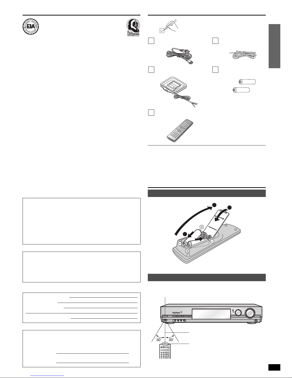
Supplied accessories
Please check and identify the supplied accessories.
Use the numbers indicated in parentheses when asking for replacement
parts. (As of August 2004)
In the U.S.A. to order accessories, refer to
“Accessory Purchases” on page 27.
In Canada to order accessories, call the dealer from whom you have
made your purchase.
The remote control
• Insert so the poles (+ and –) match those in the remote control.
• Do not use rechargeable type batteries.
Aim at the sensor, avoiding obstacles, at a maximum range of 7 m (23
feet) directly in front of the unit.
• Keep the transmission window and the unit’s sensor free from dust.
• Operation can be affected by strong light sources, such as direct
sunlight, and the glass doors on cabinets.
CAUTION!
DO NOT INSTALL OR PLACE THIS UNIT IN A
BOOKCASE, BUILT-IN CABINET OR IN ANOTHER
CONFINED SPACE. ENSURE THE UNIT IS WELL
VENTILATED. TO PREVENT RISK OF ELECTRIC SHOCK
OR FIRE HAZARD DUE TO OVERHEATING, ENSURE
THAT CURTAINS AND ANY OTHER MATERIALS DO NOT
OBSTRUCT THE VENTILATION VENTS.
CAUTION!
Do not place anything on top of this unit or block the heat
radiation vents in any way. In particular, do not place tape
decks or CD/DVD players on this unit as heat radiated from it
can damage your software.
DATE OF PURCHASE
DEALER NAME
DE AL ER AD DR ES S
TELEPHONE NUMBER
The model number and serial number of this product can be found on
either the back or the bottom of the unit. Please note them in the
space provided below and keep for future reference.
MODEL NUMBER
SERIAL NUMBER
EST. 1924
1 AC power supply cord
(K2CB2CB00006)
1 FM indoor antenna
(RSA0006-L)
1 AM loop antenna
(RSA0037)
2 Batteries
1 Remote control
(EUR7722X80) Refer to the separate booklet,
“Remote Control Operation Guide”,
for remote control operation details.
Batteries
Use
1
2
3
(R6/LR6, AA, UM-3)
1
^ ^
2 3
4 5 6
7 8 9
RECEIVER
AV SYSTEM
TV
CD
TAPE
-
MONITOR
DVD RECORDER
VCR
CH
VOLUME
ENTER
DIRECT TUNING
DVD
-
ANALOG 6CH
SPEAKERS
AB
POWER
8
6.1CH DECODING
VCR 2
PHONES
^
MULTI CONTROL
INPUT SELECTOR
VOLUME
DOWN UP
PUSH ENTER
BI-AMP
BI-WIRE
VIDEO IN
AUDIO INLR
S-VIDEO IN
7 meters (23 feet)
Transmission window
SA-XR70
Remote control signal sensor
4
Step 1
RQT7523
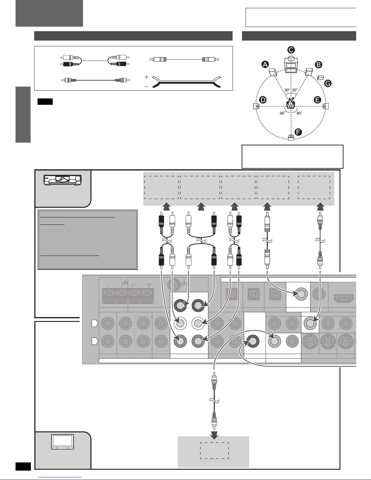
Home Theater connections
Before connecting
1
Placement of speakers
111
Stereo connection cable Coaxial cable
1
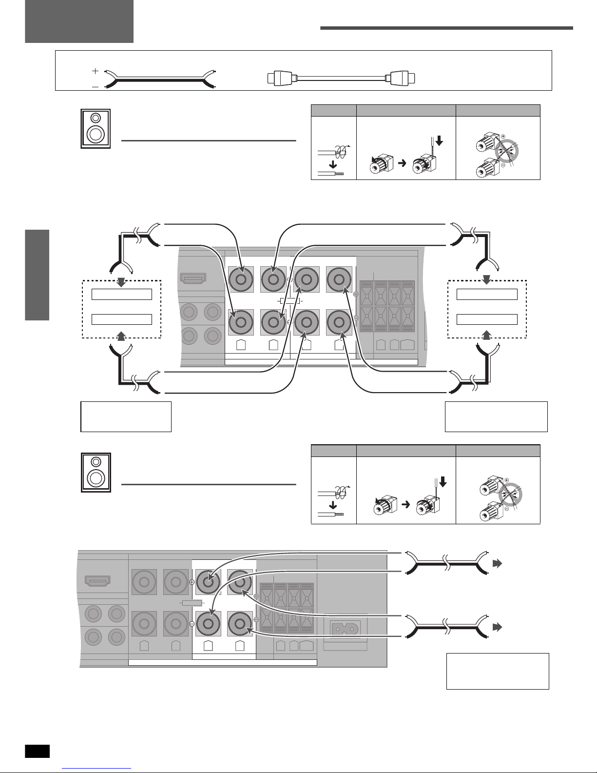
Video connection cable Speaker cable
1
Turn off all components before making any connections.
Note
• Use a digital connection to enjoy Dolby Digital or DTS and record digital sources (á pages 16 and 25).
• Use an analog connection to enjoy sources that cannot be decoded on this unit, to record
analog sources and to output through SECOND AUDIO OUT (ápages 10, 16, 24 and 25).
• When setting the On Screen Display (á page 12) connect the television’s VIDEO IN terminal
to this unit’s VIDEO TV MONITOR OUT terminal (á below).
• Enjoy higher picture quality using the S VIDEO or COMPONENT terminal (á page 9).
• Refer to pages 6 through 10 regarding connections to other equipment.
1
1
1
The front, center, and surround speakers
should be placed at approximately the same
distance from the seating area. The angles in
the diagram are approximate.
White (L)
Red (R)
75Ω GND LOOP EXT
FM ANT AM ANT
IN
CD
L
R
REC(OUT) PLAY(IN)
TA PE
LOOP ANT
GND
IN
TV DVR/VCR1
OUT IN
OUT
OPTICAL
(TV) IN
OPTICAL1 OPTICAL2
(DVR) IN
COAXIAL2
(CD) IN
OUT
IN
DVR/VCR1
MONITOR OUT
TV MONITOR O
U
YPBP
IN IN
TV DVD
D
S VIDEO
DIGITAL
CENTER
SUBWOOFER
SURROUND
FRONT
DVD /DV D 6 CH
AUDI O
COAXIAL1
IN
DVD
VIDEO
MONITOR OUT
IN
TV
(DVD) IN
OUT
SUBWOOFER
SECOND AUDIO OUT
OUT
AUDIO OUT
(SURROUND
L, R)
AUDIO OUT
(CENTER,
SUBWOOFER)
AUDIO OUT
(FRONT
L, R)
DIGITAL
AUDIO OUT
VIDEO OUT
VIDEO IN
DVD player
TV or
monitor
Changing the digital input
settings
You can change the input settings for the digital
terminals if necessary. Note the equipment you
have connected to the terminals, then change
the settings (á pages 12 or 14).
Note on analog input
Connect to FRONT L, R if your DVD player
does not have 6 channel outp ut.
Step 1
DVD player/
TV or monitor
5
Step 1
RQT7523
U
T
R
IN
DVR/VCR1
YP
B
P
R
YPBP
R
TV IN
DVD IN
COMPONENT VIDEO
FRONT B
CENTER
SURROUND
SPEAKERS (6∼8Ω) HAUT-PARLEURS
AC IN
∼
FRONT A
R L
BACK
R L
(DVD) IN
LF
R L
BI-WIREHF
Class 2 Wiring
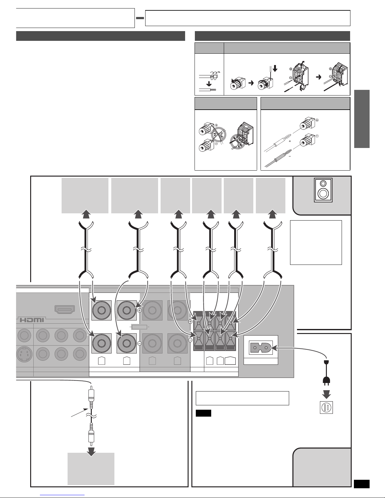
Connecting speakers
Front speakers ( left right)
Place on the left and right of the TV at seated ear height so that there is
good coherency between the picture and sound.
Center speaker ( )
Place underne ath or above the center of the TV. Aim the speaker at the
seating area.
Surround speakers ( left right)
Place on the side of or slightly behind the seating area, about one meter
(3 feet) higher than ear level.
Surround back speaker ( )
Place behind the seating area, about one meter (3 feet) higher than ear
level.
Subwoofer ( )
The subwoofer can be placed in any position as long as it is at a
reasonable distance from the TV.
Note that some experimentation with positioning can yield the
smoothest low frequency performance. Placement near a corner can
increase the apparent output level, but can result in unnatural bass.
Cable Speaker terminals
Twist
the wire.
FRONT Other terminals
Note If using 4-mm plugs
Do not short-circuit.
( )
( )
Peripheral equipment and cables sold separately unless otherwise indicated.
To connect equipment, refer to the appropriate operating instructions.
Front
right
Front
left
Surround
right
Surround
left
Surround
back
Speakers
Speaker
impedance:
Front A: 6-8 Ω
A and B:
6-8 Ω
Center: 6-8 Ω
Surround: 6-8 Ω
Center
Active
subwoofer
Monaural
connection
cable
Connect this cord after all other cables
and cords are connected.
Note
• The included AC power supply cord is for
use with this unit only. Do not use it with
other equipment.
• Do not use an AC power supply cord
from any other type of equipment with
this unit.
• If the unit is left unplugged for longer than
two weeks, all settings will revert to the
factory settings. Do the settings again if
this occurs.
Household AC outlet
(AC 120 V/60 Hz)
Speakers/
AC power supply cord
AC power
supply cord
(included)
Fully tighten the terminal,
then insert.
6
Step 2
RQT7523
Other connections
Turn off all components before making any connections.
Bi-wiring connection
You can enjoy high quality sound by connecting to speakers designed for
bi-wiring.
• Use speakers designed for bi-wiring that have a combined impedance
of 6–8 Ω.
• Be sure to press [A] and [B] at the same time to turn on the “BI-WIRE”
indicator (á page 18).
Speaker cable HDMI cable
Cable Speaker terminals Note
Twi st
the wire.
Do not short-circuit.
PB PR
PB PR
TV IN
DVD IN
CENTER
SURROUND
SPEAKERS (6∼8Ω) HAUT-PARLEURS
FRONT A
R L
R L
BACK
(DVD) IN
HF
Class 2 Wiring
R L
LFBI-WIRE
FRONT B
Front right speaker Front left speaker
HF terminals
LF terminals
HF terminals
LF terminals
Step 2
Using speaker terminal B
For connection to a second pair of speakers.
Use the A terminals to enjoy multi-channel sound.
If SPEAKERS B is selected, play will be 2-channel only.
For a multi-channel source, 2CH MIX mode will be automatically selected.
Cable Speaker terminals Note
Twi st
the wire.
Do not short-circuit.
1
YP
B
P
R
YPBP
R
TV IN
DVD IN
COMPONENT VIDEO
CENTER
SURROUND
SPEAKERS (6∼8Ω) HAUT-PARLEURS
AC IN
∼
FRONT A
R L
R L
BACK
DMI
(DVD) IN
HF
Class 2 Wiring
R L
LFBI-WIRE
FRONT B
Front right
speaker
Front left
speaker
Speaker impedance:
Front B: 6-8 Ω
A and B: 6-8 Ω
Speaker impedance:
BI-WIRE: 6-8 Ω
HF: High frequency
LF: Low frequency
7
Step 2
RQT7523
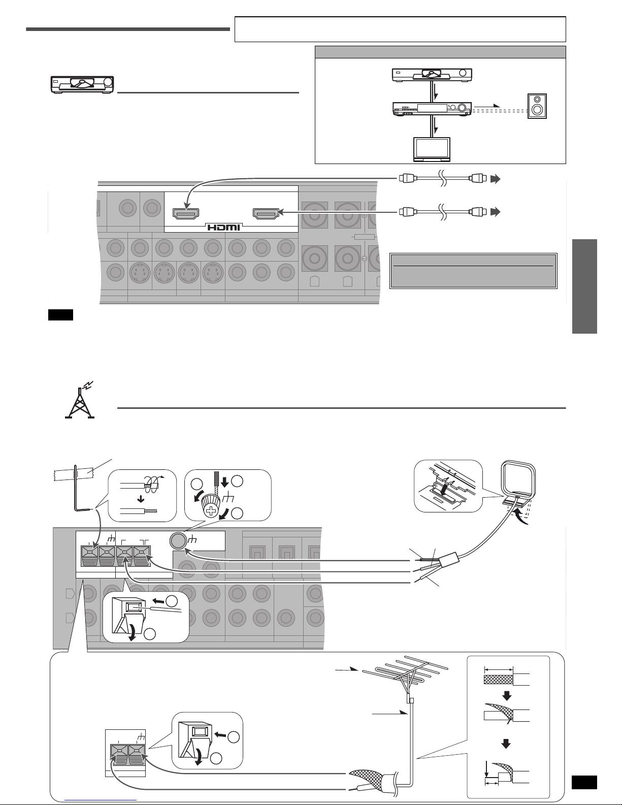
Having fun with DVDs
using HDMI connections
“HDMI” (High Definition Multimedia Interface) is a standard that enables
high-quality video and audio signals to be transmitted using a single
cable.
You can have lots of fun with this unit by means of simple connections for
high-quality video, PCM, Dolby Digital, DTS and DVD-Audio signals.
When signal transmission is commenced, the “HDMI” indicator on the unit
lights.
Path of HDMI signal
Audio and Video
Audio
Video
DVD player
or
DVD recorder
This unit
TV
Speakers
Note
• To digitally record audio from a HDMI input source, connect the recording equipment to this unit’s DIGITAL OPTICAL OUT terminal as shown on page
10. (For details on how to record, refer to page 25.)
• If the connected DVD player or DVD recorder cannot digitally output audio from DVD-Audio discs (it may be a HDMI Ver. 1.0 unit), connect it through
the DVD/DVD 6CH analog terminals. (á page 4).
• The DVD unit’s video and audio signals are not transmitted directly to the TV when you turn the unit to standby. To play a DVD on a TV only, directly
connect the DVD player or DVD recorder to the TV. (Refer to the operating instructions of the connected e quipment for further details.)
Antennas
(TV) IN
OPTICAL1 OPTICAL2
(DVR) IN
COAXIAL2
(CD) IN
OUT
IN
DVR/VCR1
MONITOR OUT
TV MONITOR OUT
YP
B
P
R
IN IN IN
TV DVD DVR/VCR1
YP
B
P
R
YPBP
R
TV IN
S VIDEO
DVD IN
COMPONENT VIDEO
FRONT B
CENTER
SURROUND
SPEAKERS (6∼8Ω) HAUT-PARLEURS
AC IN
∼
COAXIAL1
IN
DVD
VIDEO
MONITOR OUT
IN
TV FRONT A
(DVD) IN
OUT
SUBWOOFER
R L
R L
BACK
R L
Class 2 Wiring
BI-WIREHF LF
DIGITAL
(DVD) INOUT
TV
HDMI
(AV IN)
DVD
HDMI
(AV OUT)
Changing the HDMI input settings
You can change the input setting for the HDMI
terminal (á pages 12 or 14).
IN
CD
L
R
REC(OUT) PLAY(IN)
TAP E
IN
TV DVR/VCR1
OUT IN
OUT
OPTICAL
(TV) IN
OPTICAL1 OPTICAL2
(DVR) IN
COAXIAL2
(CD) IN
OUT
IN
DVR/VCR1
MONITOR OUT
TV MONITOR OUT
YP
B
P
R
IN IN IN
TV DVD DVR/VCR1
YP
B
P
R
YPBP
R
TV IN
S VIDEO
DVD IN
COMPONENT VIDEO
DIGITAL
CENTER
SUBWOOFER
SURROUND
FRONT
DVD/DVD 6CH
AUDIO
COAXIAL1
IN
DVD
VIDEO
MONITOR OUT
IN
TV FRONT A
(DVD) IN
OUT
SUBWOOFER
R
SECOND AUDIO OUT
HDMI
(DVD) INOUT
75Ω GND LOOP EXT
FM ANT
AM ANT
LOOP ANT
GND
1
2
2
1
3
LOOP ANT
GND
75Ω GND
FM ANT
LOOP
1
2
Black
Red
Adhesive tape
White
FM outdoor antenna
• Disconnect the FM indoor antenna.
• The antenna should be installed by a competent
technician.
• Twist the coaxial cable’s shield braid firmly and
connect it to the GND terminal.
FM outdoor antenna
75Ω coaxial cable
20 mm (25/32")
Shield braid
10 mm (3/8")
Core wire
AM loop antenna (included)
Keep the antenna cord away from tape
decks, DVD players, and other cords.
FM indoor antenna (included)
Fix the other end of the antenna
where reception is best.
Peripheral equipment and cables sold separately unless otherwise indicated.
To connect equipment, refer to the appropriate operating instructions.
8
Step 2
RQT7523
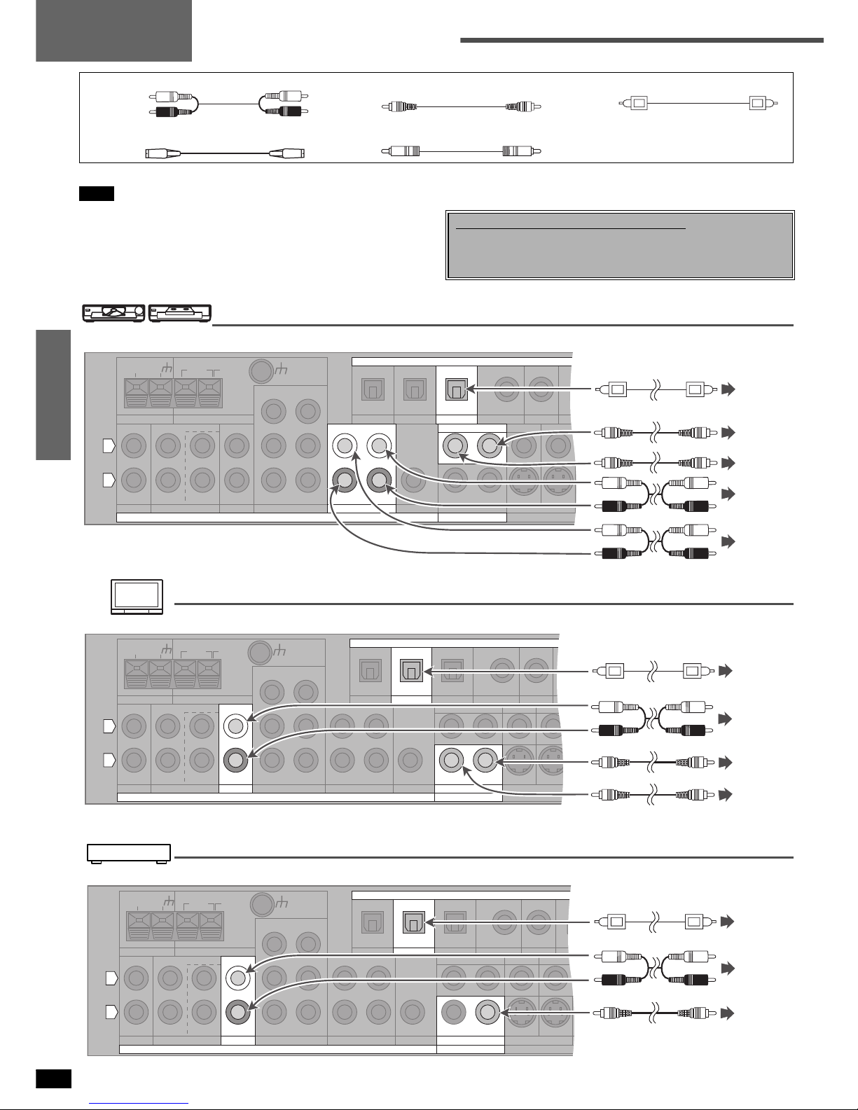
Other connections
DVD recorder/VCR
TV or monitor
Cable box or satellite receiver etc.
Stereo connection cable Video connection cable Optical fiber cable
White (L)
Red (R)
S-video connection cable Coaxial cable
Turn off all components before making any connections.
Note
• Do not shar ply bend the optical fiber cable.
• Use a digital connection to enjoy Dolby Digital or DTS and record
digital sources (á pages 16 and 25).
• Use an analog connection to enjoy sources that cannot be decoded on
this unit, to record analog sources and to output through SECOND
AUD IO OUT (ápages 10, 16, 24 and 25).
• When setting the On Screen Display mode (á page 12) connect the
television’s VIDEO IN terminal to this unit’s VIDEO TV MONITOR OUT
terminal (á below).
Changing the digital input settings
You can change the input settings for the digital terminals if necessary.
Note the equipment you have connected to the terminals, then change
the settings (á pages 12 or 14).
75Ω GND LOOP EXT
FM ANT AM ANT
IN
CD
L
R
REC(OUT) PLAY(IN)
TAPE
LOOP ANT
GND
IN
TV
OUT
OPTICAL
(TV) IN
OPTICAL1 COAXIAL2
(CD) IN
MONITOR OUT
TV MONITOR OUT
YP
B PR
IN IN IN
TV DVD DVR/VCR1
YP
B PR
YPB PR
TV IN
S VIDEO
DVD IN
COMPONENT VIDEO
CENTER
SUBWOOFER
SURROUND
FRONT
DVD /DVD 6CH
COAXIAL1
IN
DVD
MONITOR OUT
IN
TV FRO
(DVD) IN
OUT
SUBWOOFER
R
SECOND AUDIO OUT
HDMI
(DVD) INOUT
DIGITAL
OPTICAL2
(DVR) IN
OUT
IN
DVR /VC R1
DVR/VCR1
OUT IN
AUDI O VIDEO
DIGITAL
AUDIO
OUT
VIDEO
OUT
VIDEO
IN
AUDIO
OUT
AUDIO
IN
75Ω
GND LOOP EXT
FM ANT AM ANT
IN
CD
L
R
REC(OUT) PLAY(IN)
TAPE
LOOP ANT
GND
DVR/VCR1
OUT IN
OUT
OPTICAL OPTICAL2
(DVR) IN
COAXIAL2
(CD) IN
OUT
IN
DVR/VCR1
MONITOR OUT
TV MONITOR OUT
YP
B
P
R
IN IN IN
TV DVD DVR/VCR1
YP
B
P
R
YPBP
R
TV IN
S VIDEO
DVD IN
COMPONENT VIDEO
CENTER
SUBWOOFER
SURROUND
FRONT
DVD/DVD 6CH
COAXIAL1
IN
DVD
VIDEO
FRON
T
(DVD) IN
OUT
SUBWOOFER
R
SECOND AUDIO OUT
HDMI
(DVD) INOUT
IN
TV
(TV) IN
OPTICAL1
AUDIO
MONITOR OUT
IN
DIGITAL
TV
DIGITAL
OUT
AUDIO
OUT
VIDEO
OUT
VIDEO
IN
75Ω GND LOOP EXT
FM ANT AM ANT
IN
CD
L
R
REC(OUT) PLAY(IN)
TAPE
LOOP ANT
GND
DVR/VCR1
OUT IN
OUT
OPTICAL OPTICAL2
(DVR) IN
COAXIAL2
(CD) IN
OUT
IN
DVR/VCR1
MONITOR OUT
TV MONITOR OUT
YP
B
P
R
IN IN IN
TV DVD DVR/VCR1
YP
B
P
R
YPBP
R
TV IN
S VIDEO
DVD IN
COMPONENT VIDEO
CENTER
SUBWOOFER
SURROUND
FRONT
DVD/DVD 6CH
COAXIAL1
IN
DVD
FRON
T
(DVD) IN
OUT
SUBWOOFER
R
SECOND AUDIO OUT
HDMI
(DVD) INOUT
DIGITAL
(TV) IN
OPTICAL1
AUDIO
IN
TV
MONITOR OUT
IN
TV
VIDEO
DIGITAL
OUT
VIDEO
OUT
AUDIO
OUT
Step 2
9
Step 2
RQT7523
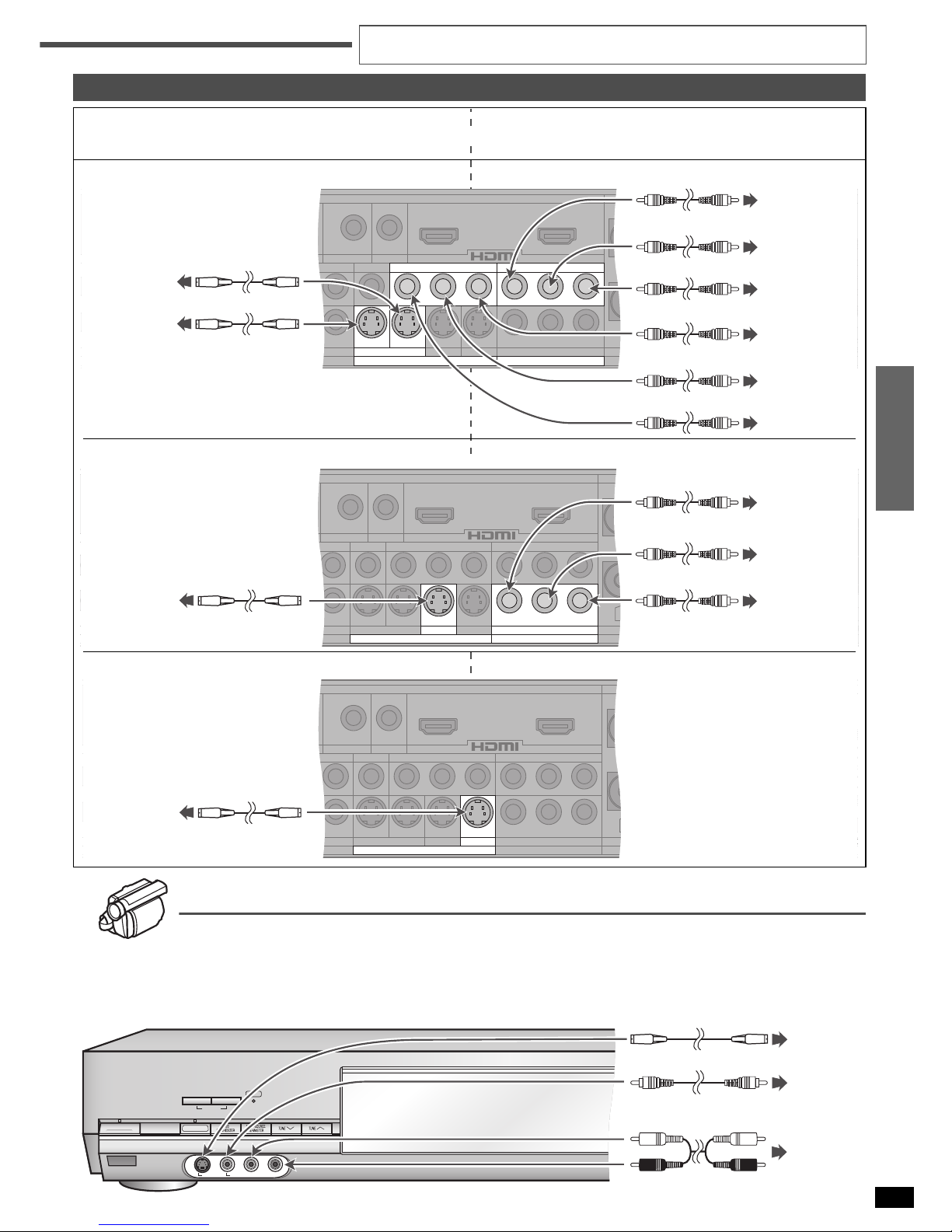
Video camera etc.
These terminals are convenient for equipment you want to connect only temporarily. Select “VCR 2” for input.
Use the S VIDEO connection for better picture quality than with the VIDEO terminal.
• Video input can only be output again through the same type of terminal.
Enjoy even higher picture quality
S VIDEO
Use this connection for better picture quality than with the VIDEO
terminals.
COMPONENT VIDEO
This connection provides high quality pictures by separating the
color (P
B and PR) and the luminance (Y) signals.
n TV, monitor, cable box or satellite receiver etc.
n DVD player
n DVD recorder/VCR
LOOP ANT
GND
DVR/VCR1
OUT IN
OUT
OPTICAL
(TV) IN
OPTICAL1 OPTICAL2
(DVR) IN
COAXIAL2
(CD) IN
OUT
IN
DVR/VCR1
IN IN
DVD DVR/VCR1
YP
B
P
R
DVD IN FRONT B
CENTER
SUR
R
SPEAKERS (6∼8Ω) HAUT-PARLEURS
CENTER
SUBWOOFER
SURROUND
FRONT
DVD/DVD 6CH
AUDI O
COAXIAL1
IN
DVD
VIDEO
MONITOR OUT
IN
TV FRONT A
(DVD) IN
OUT
SUBWOOFER
R L
R
L
R L
Class 2 Wiring
BI-WIREHF LF
DIGITAL
(DVD) INOUT
MONITOR OUT
TV MONITOR OUT
YP
B
P
R
IN
TV
YP
B
P
R
TV IN
S VIDEO COMPONENT VIDEO
COMPONENT
VIDEO OUT (Y)
COMPONENT
VIDEO OUT (P
B)
COMPONENT
VIDEO OUT (P
R)
COMPONENT
VIDEO IN (P
R)
COMPONENT
VIDEO IN (P
B)
COMPONENT
VIDEO IN (Y)
S-VIDEO OUT
S-VIDEO IN
LOOP ANT
GND
DVR/VCR1
OUT IN
OUT
OPTICAL
(TV) IN
OPTICAL1 OPTICAL2
(DVR) IN
COAXIAL2
(CD) IN
OUT
IN
DVR/VCR1
MONITOR OUT
TV MONITOR OUT
YP
B
P
R
IN IN
TV DVR/VCR1
YP
B
P
R
TV IN
FRONT B
CENTER
SURRO
U
SPEAKERS (6∼8Ω) HAUT-PARLEURS
DIGITAL
CENTER
SUBWOOFER
SURROUND
FRONT
DVD/DVD 6CH
AUDI O
COAXIAL1
IN
DVD
VIDEO
MONITOR OUT
IN
TV FRONT A
(DVD) IN
OUT
SUBWOOFER
R L
R L
R L
(DVD) INOUT
Class 2 Wiring
BI-WIREHF LF
IN
DVD
YPBP
R
S VIDEO
DVD IN
COMPONENT VIDEO
S-VIDEO OUT
COMPONENT
VIDEO OUT (P
B)
COMPONENT
VIDEO OUT (P
R)
COMPONENT
VIDEO OUT (Y)
LOOP ANT
GND
DVR/VCR1
OUT IN
OUT
OPTICAL
(TV) IN
OPTICAL1 OPTICAL2
(DVR) IN
COAXIAL2
(CD) IN
OUT
IN
DVR/VCR1
MONITOR OUT
TV MONITOR OUT
YP
B
P
R
IN IN
TV DVD
YP
B
P
R
YPBP
R
TV IN
DVD IN
COMPONENT VIDEO
FRONT B
CENTER
SURR
O
SPEAKERS (6∼8Ω) HAUT-PARLEURS
DIGITAL
CENTER
SUBWOOFER
SURROUND
FRONT
DVD/ DVD 6C H
AUDI O
COAXIAL1
IN
DVD
VIDEO
MONITOR OUT
IN
TV FRONT A
(DVD) IN
OUT
SUBWOOFER
R L
R L
R L
(DVD) INOUT
Class 2 Wiring
BI-WIREHF LF
IN
DVR/VCR1
S VIDEO
S-VIDEO OUT
SPEAKERS
AB
POWER
8
6.1CH DECODING
AUDIO INLR
VCR 2
^
BI-AMP
BI-WIRE
VIDEO IN
S-VIDEO IN
VIDEO
OUT
AUDIO
OUT
S-VIDEO
OUT
or
Peripheral equipment and cables sold separately unless otherwise indicated.
To connect equipment, refer to the appropriate operating instructions.
or
 Loading...