


Operating Instructions
AV Control Receiver
Model No. SA-XR58
Dear customer
Thank you for purchasing this product.
Before connecting, operating or adjusting this product,
please read the instructions completely.
Please keep this manual for future reference.
E
RQTV0156-1B

ENGLISH
RQTV0156
Safety precautions
Placement
Set the unit up on an even surface away from direct sunlight, high
temperatures, high humidity, and excessive vibration. These conditions
can damage the cabinet and other components, thereby shortening the
unit’s service life.
Do not place heavy items on the unit.
Voltage
Do not use high voltage power sources. This can overload the unit and
cause a fire.
Do not use a DC power source. Check the source carefully when
setting the unit up on a ship or other place where DC is used.
Safety precautions
AC mains lead protection
Ensure the AC mains lead is connected correctly and not damaged.
Poor connection and lead damage can cause fire or electric shock. Do
not pull, bend, or place heavy items on the lead.
Grasp the plug firmly when unplugging the lead. Pulling the AC mains
lead can cause electric shock.
Do not handle the plug with wet hands. This can cause electric shock.
Foreign matter
CAUTION!
DO NOT INSTALL OR PLACE THIS UNIT IN A BOOKCASE,
•
BUILT-IN CABINET OR IN ANOTHER CONFINED SPACE.
ENSURE THE UNIT IS WELL VENTILATED. TO PREVENT
RISK OF ELECTRIC SHOCK OR FIRE HAZARD DUE TO
OVERHEATING, ENSURE THAT CURTAINS AND ANY OTHER
MATERIALS DO NOT OBSTRUCT THE VENTILATION VENTS.
DO NOT OBSTRUCT THE UNIT’S VENTILATION OPENINGS
•
WITH NEWSPAPERS, TABLECLOTHS, CURTAINS, AND
SIMILAR ITEMS.
DO NOT PLACE SOURCES OF NAKED FLAMES, SUCH AS
•
LIGHTED CANDLES, ON THE UNIT.
DISPOSE OF BATTERIES IN AN ENVIRONMENTALLY
•
FRIENDLY MANNER.
WARNING:
TO REDUCE THE RISK OF FIRE, ELECTRIC SHOCK OR
PRODUCT DAMAGE, DO NOT EXPOSE THIS APPARATUS TO
RAIN, MOISTURE, DRIPPING OR SPLASHING AND THAT NO
OBJECTS FILLED WITH LIQUIDS, SUCH AS VASES, SHALL BE
PLACED ON THE APPARATUS.
THIS UNIT IS INTENDED FOR USE IN MODERATE CLIMATES.
This product may receive radio interference caused by mobile
telephones during use. If such interference is apparent, please
increase separation between the product and the mobile telephone.
Do not let metal objects fall inside the unit. This can cause electric
shock or malfunction.
Do not let liquids get into the unit. This can cause electric shock or
malfunction. If this occurs, immediately disconnect the unit from the
power supply and contact your dealer.
Do not spray insecticides onto or into the unit. They contain flammable
gases which can ignite if sprayed into the unit.
Service
Do not attempt to repair this unit by yourself. If sound is interrupted,
indicators fail to light, smoke appears, or any other problem that is
not covered in these operating instructions occurs, disconnect the AC
mains lead and contact your dealer or an authorized service center.
Electric shock or damage to the unit can occur if the unit is repaired,
disassembled or reconstructed by unqualified persons.
Extend operating life by disconnecting the unit from the power source if
it is not to be used for a long time.
The socket outlet shall be installed near the equipment and easily
accessible or the mains plug or an appliance coupler shall remain
readily operable.
CAUTION!
Do not place anything on top of this unit or block the heat radiation
vents in any way. In particular, do not place DVD recorder or CD/
DVD players on this unit as heat radiated from it can damage your
software.
HDMI, the HDMI logo and High-Definition Multimedia
Interface are trademarks or registered trademarks of HDMI
Licensing LLC.
HDAVI ControlTM is a trademark of Matsushita Electric
Industrial Co., Ltd.
Manufactured under license from Dolby Laboratories.
“Dolby”, “Pro Logic” and the double-D symbol are trademarks
of Dolby Laboratories.
“DTS”, “DTS-ES”, “Neo:6” and “DTS 96/24” are trademarks of
Digital Theater Systems, Inc.
Refer to the back cover for
“Supplied accessories”.
2
ENGLISH
RQTV0156
AUTO
SPEAKER SETUP
ADVANCED
DUAL AMP
BI-AMP
SPEAKERS
A B
AUTO DETECTOR
SURROUND
AUX SETUP MIC
MENU
SETUP
RETURN
INPUT SELECTOR
ENTER
VOLUME
HDMI
TUNE
S VIDEO IN
VIDEO IN
L
A
U
D
I
O
I
N
R
Table of contents
Before use
Safety precautions ...................................................... 2
The remote control .............................................................. 3
Control guide ............................................................... 4
Remote control/The main unit and display ....................... 4
Connections
Home Theater connections ........................................ 5
Connecting your television and DVD equipment ............. 5
High-quality audio and video simply with HDMI connection
.. 5
Connections for high-resolution video (components without
an HDMI) ............................................................................. 6
Connections for standard-resolution video (components
without an HDMI) ................................................................ 7
Connection with 21-pin scart cable .................................... 7
6-channel discrete connection (for high-quality DVD-Audio
sound) ................................................................................. 8
Analogue audio connections ............................................... 8
Playing audio from your television through speakers
connected to this unit .......................................................... 9
Connecting a combination DVD recorder/VCR ................... 9
Connecting other equipment .................................... 10
Connecting a set top box (cable or satellite)/Connecting a
VCR/Connecting a CD player/Connecting a video camera
or other portable device ...................................................10
Connecting the antennas and AC mains lead ................ 11
Using headphones ............................................................ 11
Speaker connections ................................................ 12
Connecting speakers ........................................................ 12
Connections and placement to suit the number of speakers
you have ........................................................................... 12
Connecting biwireable speakers/Connecting a second pair
of front speakers ............................................................... 13
Before playback ......................................................... 14
Auto speaker setup ........................................................... 14
Process for auto speaker setup ........................................ 14
Troubleshooting for auto speaker setup ........................... 16
Automatic speaker detection ........................................... 17
Speaker output and level .................................................. 17
Basic operations
Enjoying Home Theater features ............................. 18
Basic play .......................................................................... 18
Digital signals this unit can play/Signal indicators ............. 19
Playback options ....................................................... 20
Using SPEAKERS B/ADVANCED DUAL AMP/BI-AMP/
Playing DVD-Audio ........................................................... 20
Using HDAVI ControlTM .............................................. 21
One-touch Home Theater .................................................21
Operations
Surround sound ......................................................... 22
Dolby Pro LogicΙΙx ............................................................ 22
Adjusting the Dolby Pro LogicΙΙx “MUSIC” mode ............ 22
NEO:6 .................................................................................23
Adjusting the NEO:6 “MUSIC” mode ............................... 23
SFC (Sound Field Control) ...............................................24
Adjusting SFC (Sound Field Control) ................................ 25
Receiver settings ....................................................... 26
Basic operations ...............................................................26
Speaker and size settings/Distance/LR BI-WIRE setting/
Low-pass filter/Auto Setup ................................................ 27
Digital input settings/Input signal/Bi-amp settings ............. 28
HDMI settings/Turning the ADVANCED DUAL AMP
off/Clear audio at low volume/Attenuating analogue input/
Delaying audio/Resetting factory settings ......................... 29
Sound effects/Other functions ................................. 30
Basic operations ...............................................................30
Sound effects-Adjusting the bass/Adjusting the treble/
Adjusting front speaker balance/Adjusting the subwoofer
level ................................................................................... 31
Other functions-Selecting audio channels/Adjusting the
dimness of the display/Sleep timer/Muting ....................... 31
The radio .................................................................... 32
Manual tuning .................................................................... 32
Preset tuning .....................................................................33
Presetting stations/Selecting channels ............................. 33
RDS broadcasts ......................................................... 34
Changing the display ........................................................ 34
Using the remote control with other equipment ..... 34
Television ........................................................................... 34
DVD recorder/DVD player ................................................. 35
VCR/CD player ................................................................... 36
Changing the remote control code/Enter a code to operate
some equipment ............................................................... 37
Reference
Specifications (DIN 45 500) ....................................... 38
Help messages .......................................................... 38
Troubleshooting guide .............................................. 39
Supplied accessories ................................. Back cover
Maintenance ................................................ Back cover
Table of contents
The remote control
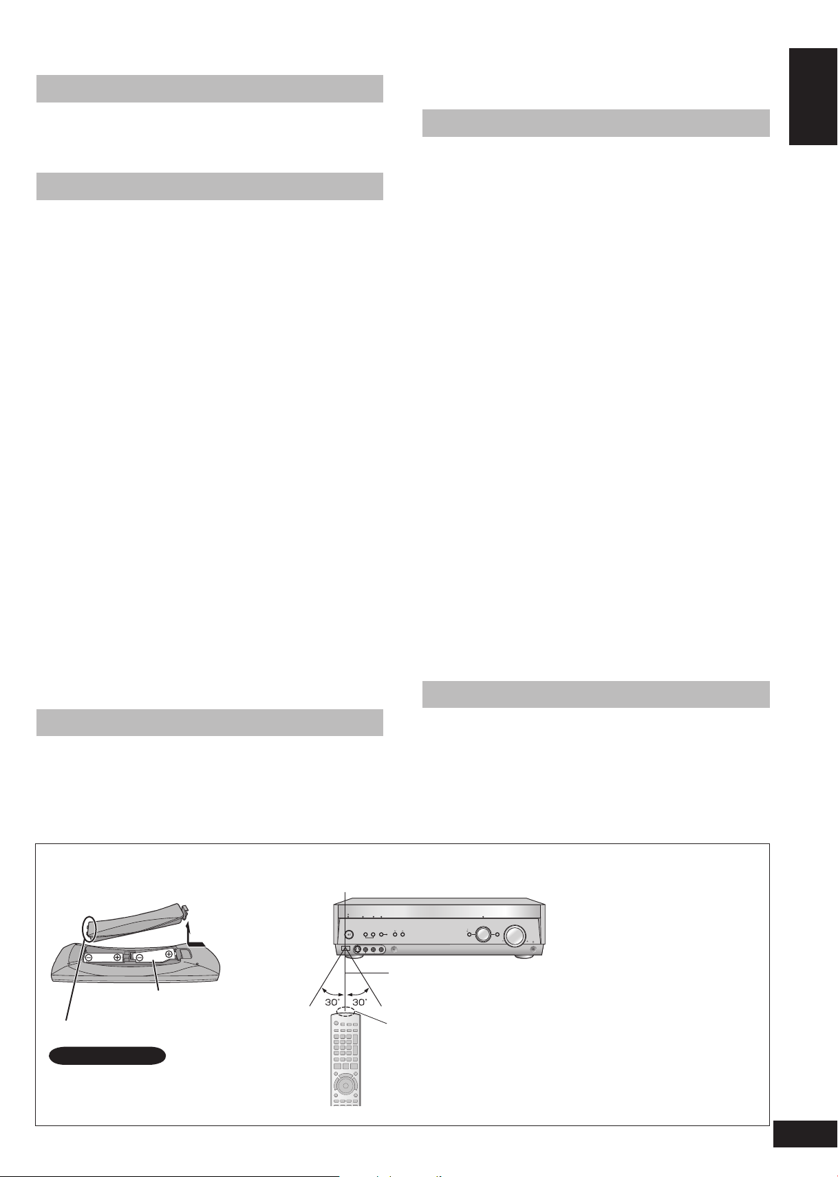
Batteries
Press on the tab to open.
Insert this side first when closing.
(R6/LR6, AA)
Note
Insert so the poles (+ and –) match
•
those in the remote control.
Do not use rechargeable type
•
batteries.
Use
Sensor
7 meters (actual distance
depends on the angle)
Transmitter
Caution
Ensure there are no obstacles
•
between the remote control and
the main unit.
Strong light sources (direct
•
sunlight or strong fluorescent
light) can interfere with
operation.
Keep the transmitter and sensor
•
free from dust.
When you set the unit in a
cabinet
Thick or coloured glass can
reduce the operating distance.
3
Control guide
O
N
E
T
O
U
C
H
P
L
A
Y
D
I
R
E
C
T
N
A
V
I
G
A
T
O
R
T
O
P
M
E
N
U
F
U
N
C
T
I
O
N
S
0
RECEIVER
AV
SYSTEM
TV
RECORDER
DVD
DV
D
PLAYER
ANALOG 6CH
VCRCD
TUNER
BAND
CH
VOLUME
DIRECT TUNING
SKIP
SLOW/SEARCH
STOP
PAUSE
PLAY
DRIVE SELECT
DVD RECORDER
MANUAL SKIP
ENTER
SUB MENU RETURN
OFF
SUBWOOFER
TEST
TV
LEVEL
EFFECT
VOL
NEO : 6
SFC
MUSIC MOVIE
DIMMER
MUTING
TV/AV
DISC
-/--
AUTO
A
B
2CH MIX
SPEAKERS
BI-WIRE
TUNED
MONO ST
PS
PTY
SLEEP
PCM
cm
DTS 96/24DTS
-ES
DIGITA
L EX
EX
RDS M
DIGITAL INPUT
kHz
MHz
AUTO
SPEAKER SETUP
ADVANCED
DUAL AMP
BI-AMP
SPEAKERS
A B
AUTO DETECTOR
SURROUND
AUX SETUP MIC
MENU
SETUP
RETURN
INPUT SELECTOR
ENTER
VOLUME
HDMI
TUNE
S VIDEO IN
VIDEO IN
L
AU
D
IO IN
R
Remote control
ENGLISH
1
2
3
Control guide
4
5
6
7
10
11
12
13
14
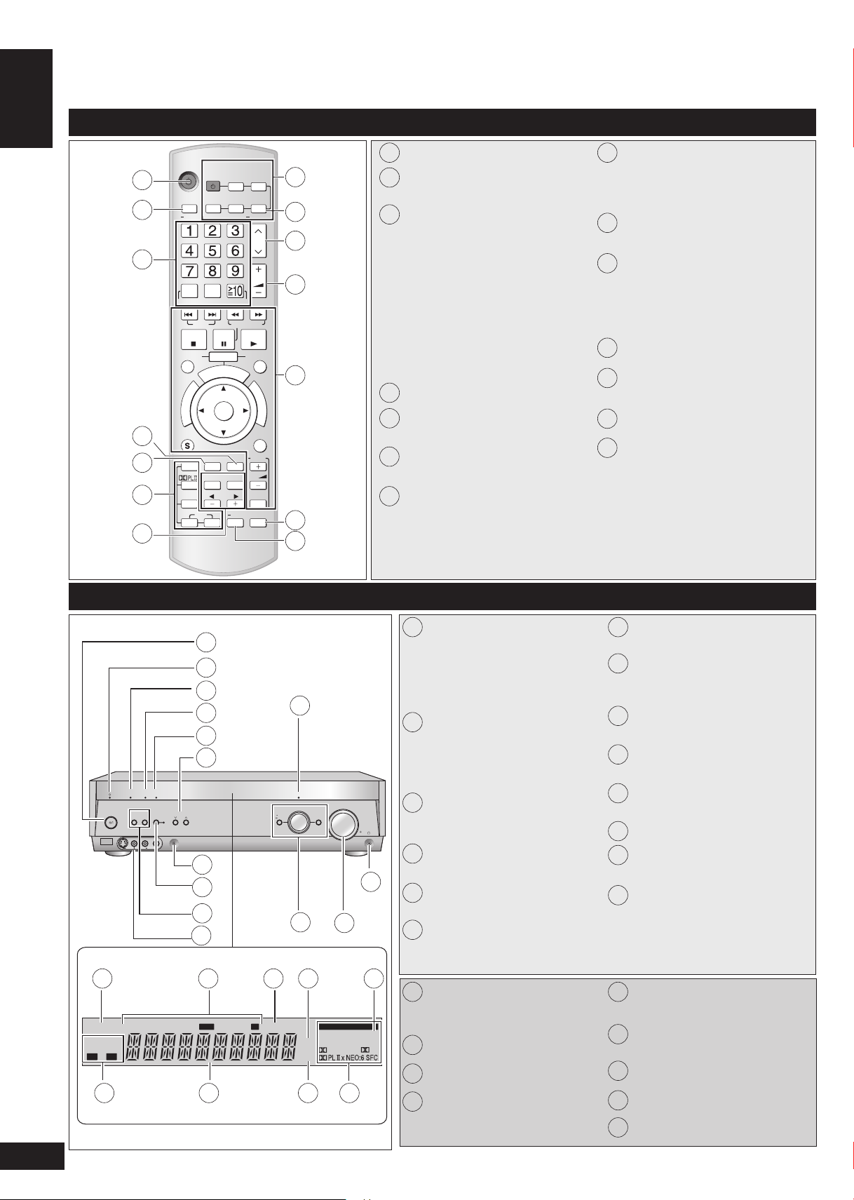
Power button
1
8
For selecting tuner/ For switching FM
2
or AM (➡ page 32)
9
3
For selecting stations directly
TUNER (➡ page 32)
For selecting channels
TUNER (➡ page 33)
TV (➡ page 34)
DVD recorder (➡ page 35)
VCR (➡ page 36)
For selecting tracks and chapters
DVD recorder/DVD player (➡ page
35)
For selecting tracks
CD player (➡ page 36)
4
To dim the display (➡ page 31)
5
To adjust the subwoofer level
(➡ page 31)
6
For selecting sound modes
(➡ pages 22, 23, and 24)
For speaker adjustments (➡ page 17)
7
Switches on or off other equipment/
8
switches the source/ switches the
remote control mode
(➡ pages 34 to 37)
For switching on the DVD-Audio
9
6-channel mode (➡ page 20)
10
To change channels
TUNER (➡ page 33)
TV (➡ page 34)
DVD recorder (➡ page 35)
VCR (➡ page 36)
11
Adjusts volume (➡ page 17)
For operating other equipment
12
(➡ pages 21 and 34 to 37)
13
To mute the volume (➡ page 31)
For auto speaker setup
14
(➡ pages 14 to 16)
For testing speaker output
(➡ page 17)
For changing sound quality and
sound field (➡ pages 22, 23, and 25)
The main unit and display
15 16 17 18 19
20 21 22 23
4
RQTV0156
1
2
3
4
5
6
7
8
9
10
Standby/on switch [8]
1
Press to switch the unit from on
to standby mode or vice versa.
In standby mode, the unit is still
consuming a small amount of
11
power.
Standby indicator [^]
2
When the unit is connected to the
AC mains supply, this indicator
lights up in standby mode and goes
out when the unit is turned on.
Flashes during auto speaker setup.
3
Lights when the setup finishes
(➡ pages 14 to 16)
4
12
Lights when you are using the
Advanced Dual Amp (➡ page 20)
Lights when you are using the bi-
5
amp (➡ page 20)
14
13
6
For tuning the radio and selecting
Setup microphone jack
7
(➡ page 14)
For switching surround (The
8
indicator lights when you are using
this feature) (➡ page 18)
For selecting front speakers
9
(➡ pages 11, 17, 18, and 20)
For connecting other equipment
10
(➡ pages 10)
Lights when you are using the
11
HDMI connections (➡ page 5)
12
Headphone jack (➡ page 11)
13
Adjusts volume (➡ pages 11 and
18)
For switching input (➡ page 18)
14
Also used during menu and setup
operation
preset stations (➡ pages 32 to 33)
Lights when multi-channel sources
15
are being down-mixed to 2
channels
Radio indicators
16
Sleep timer indicator
17
Units for speaker distance and
18
Bi-amp delay time
Lights when you have set the PCM
19
FIX mode
Shows the front speaker mode you
20
have selected
21
General display
22
Frequency unit indicators
23
Digital signal format (➡ page 19)
DVD
(TV/STB)
OPTICAL1
Y PB PR Y YPB PR PB PR
BI-WIRE
LF HF
DIGITAL IN
(DVD RECORDER)
(DVD PLAYER)
(CD)
OPTICAL2 COAXIAL1
COAXIAL2
OUT (DVD RECORDER) IN
S VIDEO
OUT
TV MONITORINDVD PLAYERINDVD RECORDERINTV/STB
OUT
VIDEO
TV MONITOR DVD PLAYER
IN IN
DVD RECORDERINVCRINTV/STB
L
R
IN
CD
CENTER
SUBWOOFER
SURROUND
FRONT
DVD/DVD 6CH IN
AUDIO
IN
DVD RECORDERINVCRINTV/STB
OUT
SUBWOOFER
LR
FRONT A FRONT BLRCENTER SURROUNDLRSURROUND BACK
LR
TV MONITOR OUT DVD RECORDER IN
COMPONENT VIDEO
TV / STB IN
LOOP EXTLOOP EXTLOOP EXT
AM ANTFM ANT
LOOP ANT
GND
SPEAKERS
Home Theater connections
AUTO
SPEAKER SETUP
ADVANCED
DUAL AMP
BI-AMP
SPEAKERS
A B
AUTO DETECTOR
SURROUND
AUX SETUP MIC
MENU
SETUP
RETURN
INPUT SELECTOR
ENTER
VOLUME
HDMI
TUNE
S VIDEO IN
VIDEO IN
L
A
U
D
I
O
I
N
R
[HDMI]
Turn off all components before making any connections.
•
Peripheral equipment and cables sold separately unless
•
otherwise indicated.
To connect equipment, refer to the appropriate operating
•
instructions.
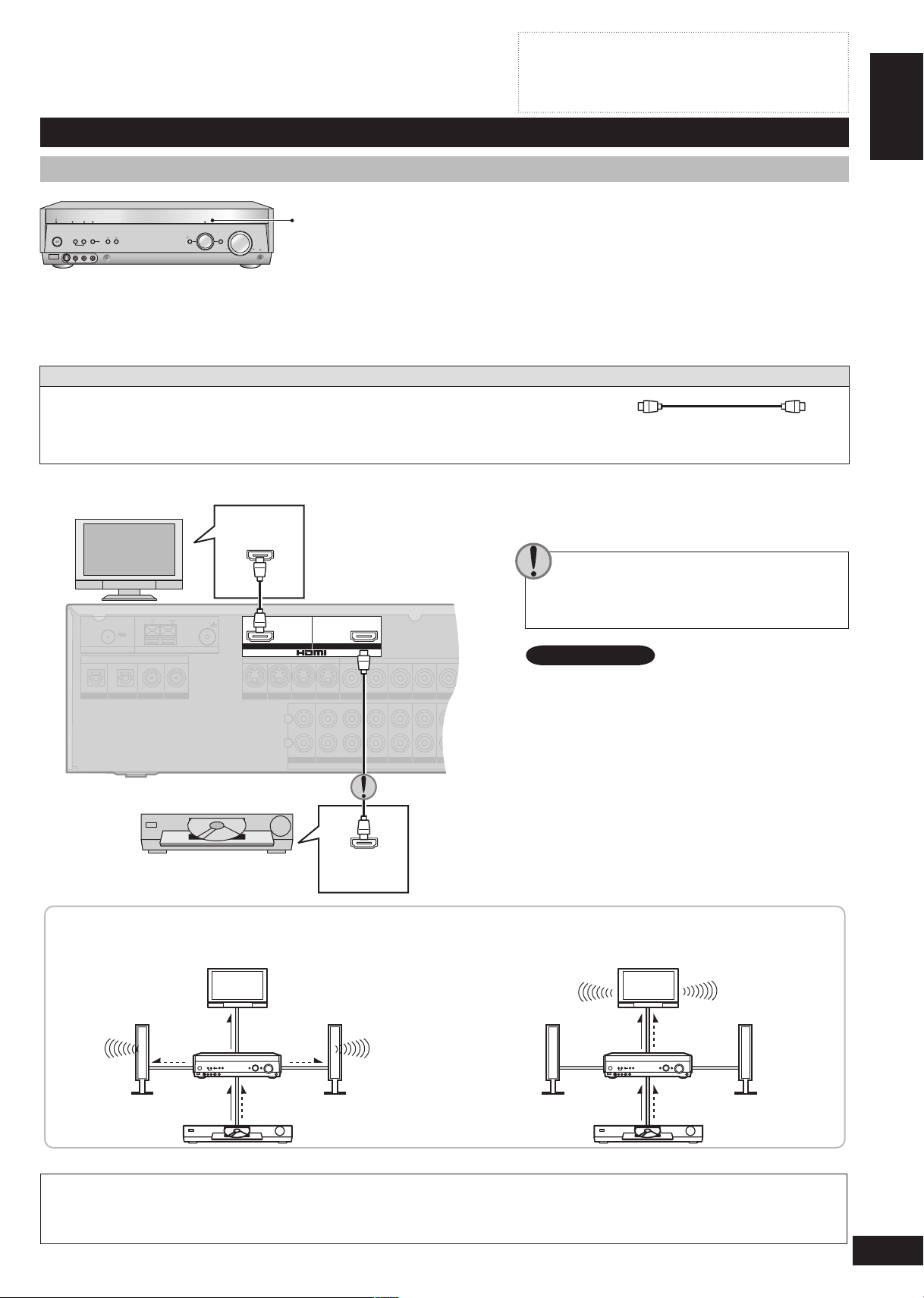
Connecting your television and DVD equipment
High-quality audio and video simply with HDMI connection
The HDMI (High Definition Multimedia Interface) connection means you only
•
need one cable to transmit digital audio and video between two pieces of
equipment. It also carries a command signal that allows you to control your
Panasonic TV (VIERA) or DVD recorder (DIGA) with one touch of a button
(➡ page 21).
DVD-Audio multi-channel audio is carried as a digital signal. Some DVD
•
equipment (e.g. with HDMI Ver.1.0) cannot output multi-channel audio as a
digital signal. Use the 6-channel discrete connection (➡ pages 8 and 20) if this
is the case.
The HDMI indicator lights when you are using this connection.
•
Connection cable
Video and Audio cable
HDMI Cable
(Use a Panasonic HDMI cable for best results.)
[Recommended part number: RP-CDHG15 (1.5 m), RP-CDHG30 (3.0 m), RP-CDHG50 (5.0 m) etc.]
Use only HDMI cables that have the HDMI logo (as shown on the cover).•
To play audio from the television through speakers connected to this unit, ➡ page 9.
TV HDMI
(AV IN)
ENGLISH
Home Theater connections
Rear panel
If you decide to connect a DVD player through
the HDMI, change the “HDMI settings” (➡ page
29).
Note
Connect only DVD equipment to the HDMI input
terminal of the unit. Connecting other equipment
may prevent the output of sounds or show distorted
pictures.
In such cases, see “Connecting other equipment”,
➡ page 10, for connections other than HDMI.
DVD equipment
DVD HDMI
(AV OUT)
Audio and video signal flow when you have used HDMI connections
The audio and video signals from DVD equipment pass through to the television even if this unit is set to standby.
When this unit is on
Video
Audio Audio
Video Audio
For your reference
Audio signals from HDMI connection takes priority to digital terminal connections (➡ page 6 and 7).
•
This unit’s HDMI can carry video signals up to 1125i (1080i) (even when this unit is in standby mode).
•
This unit
TV
DVD equipment
Speakers
1125i: an interlace (jump scanning) system that divides 1,125 scan lines in two and sends each half alternately every 1/60
second.
When this unit is in
standby mode
(in standby ON condition,
➡ page 29)
Video Audio
This unit
Video Audio
TV
DVD equipment
Speakers
5
RQTV0156
ENGLISH
RQTV0156
(TV/STB)
OPTICAL1
Y PBPRY YPBP
R
PBP
R
BI-WIRE
LF HF
DIGITAL IN
(DVD RECORDER)
(DVD PLAYER)
(CD)
OPTICAL2 COAXIAL1
COAXIAL2
OUT (DVD RECORDER) IN
S VIDEO
OUT
TV MONITOR
IN
DVD PLAYERINDVD RECORDERINTV/STB
OUT
VIDEO
TV MONITOR DVD PLAYER
IN IN
DVD RECORDERINVCRINTV/STB
L
R
IN
CD
CENTER
SUBWOOFER
SURROUND
FRONT
DVD/DVD 6CH IN
AUDIO
IN
DVD RECORDERINVCRINTV/STB
OUT
SUBWOOFER
LR
FRONT A FRONT BLRCENTER SURROUNDLRSURROUND BACK
LR
TV MONITOR OUT DVD RECORDER IN
COMPONENT VIDEO
TV / STB IN
SPEAKERS
LOOP EXTLOOP EXTLOOP EXT
AM ANTFM ANT
LOOP ANT
GND
Y
P
B
P
R
Y
P
B
P
R
Home Theater connections
Connecting your television and DVD equipment (cont.)
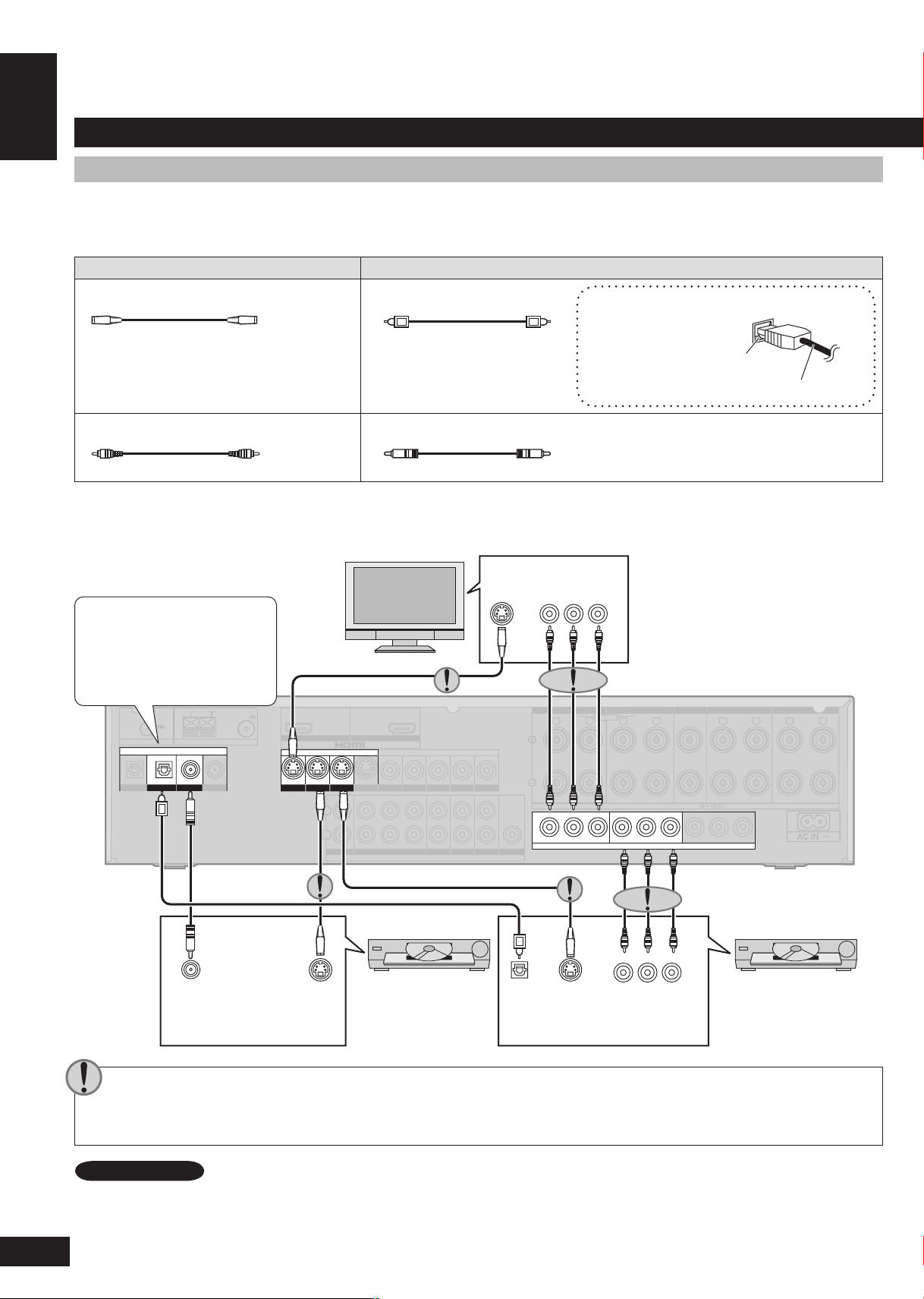
Connections for high-resolution video (components without an HDMI)
Connection cable
Check the connections on your equipment and prepare the necessary cables.
•
Your equipment will have more than one way of connecting video, so decide which best suits your needs.
•
Video cable Audio cable
S-VIDEO connection cable Optical fibre cable
Video connection cable Coaxial cable
Home Theater connections
Connecting the optical fibre cable
Note the shape and fit it
correctly into the terminal.
Do not bend!
To play audio from the television through speakers connected to this unit, ➡ page 9.
TV
IN
COMPONENT
VIDEO IN
S-VIDEO
Digital input settings
You can change the input
settings for the digital terminals
if necessary (➡ page 28).
DIGITAL
AUDIO
S-VIDEO
OUT
OUT
(OPTICAL)
DIGITAL
AUDIO OUT
(COAXIAL)
The video terminals
Connect the video cables in sets so that you have the same type for input and output.
•
The component video connection provides the best colour reproduction by separating the luminance (Y) and colour (red: PR or
•
S-VIDEO
OUT
DVD player
CR, and blue: PB or CB) signals.
COMPONENT
VIDEO OUT
Rear panel
DVD recorder
6
Note
To connect a set top box (cable or satellite), ➡ page 10.
ENGLISH
RQTV0156
D)
OUT (DVD RECORDER) IN
S VIDEO
OUT
TV MONITORINDVD PLAYERINDVD RECORDERINTV/STB
OUT
VIDE
O
TV MONITOR DVD PLAYER
IN IN
DVD RECORDERINVCRINTV/STB
L
R
IN
CD
CENTER
SUBWOOFER
SURROUND
FRONT
DVD/DVD 6CH IN
AUDIO
IN
DVD RECORDERINVCRINTV/STB
OUT
SUBWOOFER
EXTEXTEXT
LOOP ANT
GND
(TV/STB)
OPTICAL1
Y PB PR Y YPB PR PB PR
BI-WIRE
LF HF
DIGITAL IN
(DVD RECORDER)
(DVD PLAYER)
(CD)
OPTICAL2 COAXIAL1
COAXIAL2
OUT (DVD RECORDER) IN
S VIDEO
OU
T
TV MONITORINDVD PLAYERINDVD RECORDERINTV/STB
OUT
VIDEO
TV MONITOR DVD PLAYER
IN IN
DVD RECORDERINVCRINTV/STB
L
R
IN
CD
CENTER
SUBWOOFER
SURROUND
FRONT
DVD/DVD 6CH IN
AUDIO
IN
DVD RECORDERINVCRINTV/STB
OUT
SUBWOOFER
LR
FRONT A FRONT BLRCENTER SURROUNDLRSURROUND BACK
LR
TV MONITOR OUT DVD RECORDER IN
COMPONENT VIDEO
TV / STB IN
LOOP EXTLOOP EXTLOOP EXT
AM ANTFM ANT
LOOP ANT
GND
SPEAKERS
Turn off all components before making any connections.
•
Peripheral equipment and cables sold separately unless
•
otherwise indicated.
To connect equipment, refer to the appropriate operating
•
instructions.
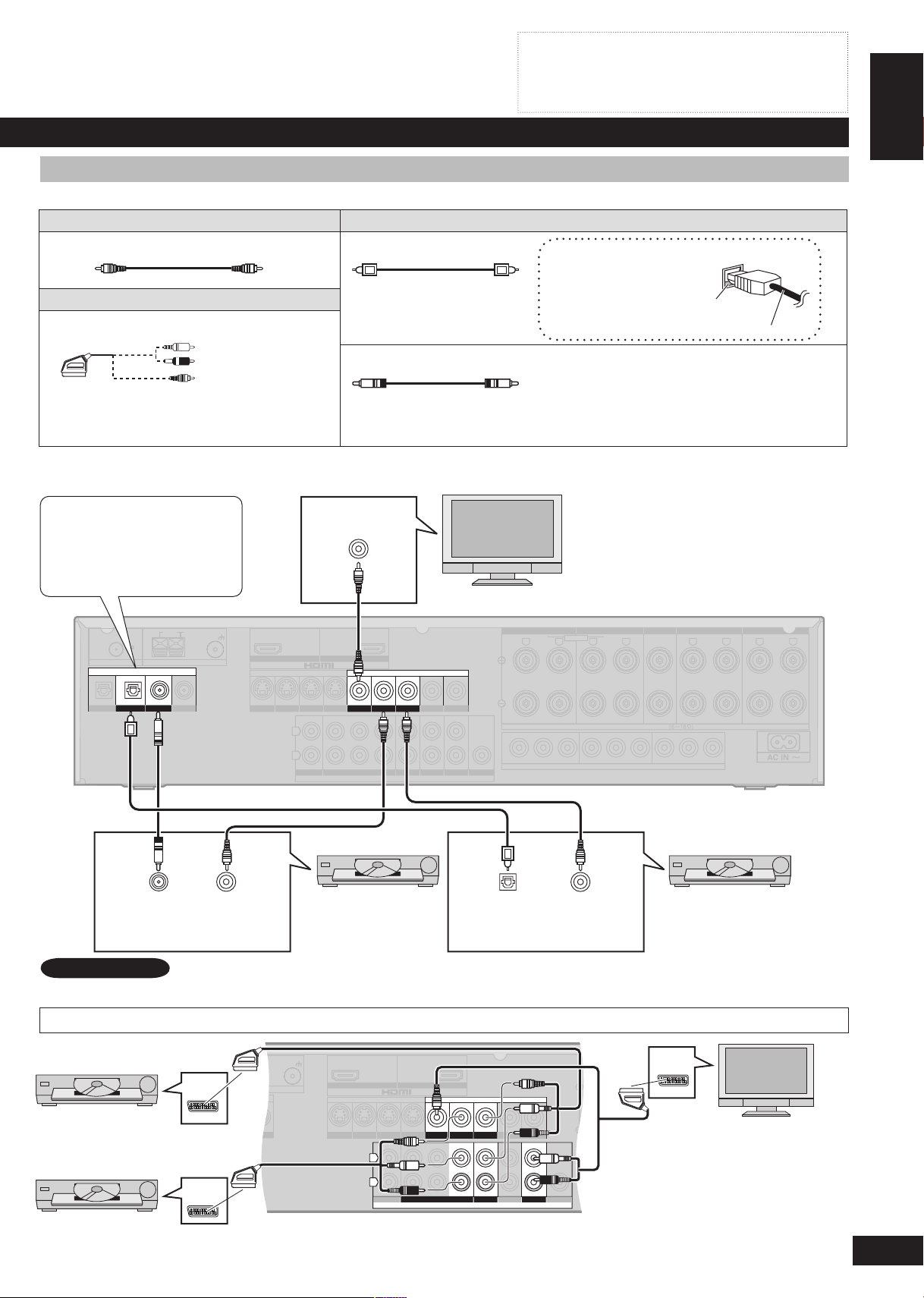
Connections for standard-resolution video (components without an HDMI)
Connection cable
Video cable Audio cable
Video connection cable Optical fibre cable
Scart cable
21-pin scart cable
Coaxial cable
You will need an adaptor to connect equipment
with a 21-pin scart terminal.
To play audio from the television through speakers connected to this unit, ➡ page 9.
Connecting the optical fibre cable
Note the shape and fit it
correctly into the terminal.
Do not bend!
Home Theater connections
Digital input settings
You can change the input
settings for the digital
terminals if necessary
(➡ page 28).
DIGITAL
AUDIO OUT
(COAXIAL)
VIDEO
OUT
VIDEO IN
TV
DVD player DVD recorder
DIGITAL
AUDIO OUT
VIDEO
OUT
(OPTICAL)
Rear panel
Note
AV
AV
To connect a set top box (cable or satellite), ➡ page 10.
Connection with 21-pin scart cable
DVD recorder
DVD player
AV
Rear panel
TV
7
ENGLISH
RQTV0156
(TV/STB)
OPTICAL1
Y PB PR Y YPB PR PB PR
BI-WIRE
LF
HF
DIGITAL IN
(DVD RECORDER)
(DVD PLAYER)
(CD)
OPTICAL2 COAXIAL1
COAXIAL2
OUT (DVD RECORDER) IN
S VIDEO
OU
T
TV MONITORINDVD PLAYERINDVD RECORDERINTV/STB
OUT
VIDE
O
TV MONITOR DVD PLAYER
IN IN
DVD RECORDERINVCRINTV/STB
L
R
IN
CD
CENTER
SUBWOOFER
SURROUND
FRONT
DVD/DVD 6CH IN
AUDIO
IN
DVD RECORDERINVCRINTV/STB
OUT
SUBWOOFER
LR
FRONT A FRONT BLRCENTER SURROUNDLRSURROUND BACK
LR
TV MONITOR OUT DVD RECORDER IN
COMPONENT VIDEO
TV / STB IN
LOOP EXTLOOP EXTLOOP EXT
AM ANTFM ANT
LOOP ANT
GND
SPEAKERS
(TV/STB)
OPTICAL1
Y PBPRY YPBP
R
PBP
R
BI-WIRE
LF HF
DIGITAL IN
(DVD RECORDER)
(DVD PLAYER)
(CD)
OPTICAL2 COAXIAL1
COAXIAL2
OUT (DVD RECORDER) IN
S VIDEO
OUT
TV MONITOR
IN
DVD PLAYER
IN
DVD RECORDERINTV/STB
OUT
VIDEO
TV MONITOR DVD PLAYER
IN IN
DVD RECORDERINVCRINTV/STB
L
R
IN
CD
CENTER
SUBWOOFER
SURROUND
FRONT
DVD/DVD 6CH IN
AUDIO
IN
DVD RECORDERINVCRINTV/STB
OUT
SUBWOOFER
LR
FRONT A FRONT BLRCENTER SURROUNDLRSURROUND BACK
LR
TV MONITOR OUT DVD RECORDER IN
COMPONENT VIDEO
TV / STB IN
SPEAKERS
LOOP EXTLOOP EXTLOOP EXT
AM ANTFM ANT
LOOP ANT
GND
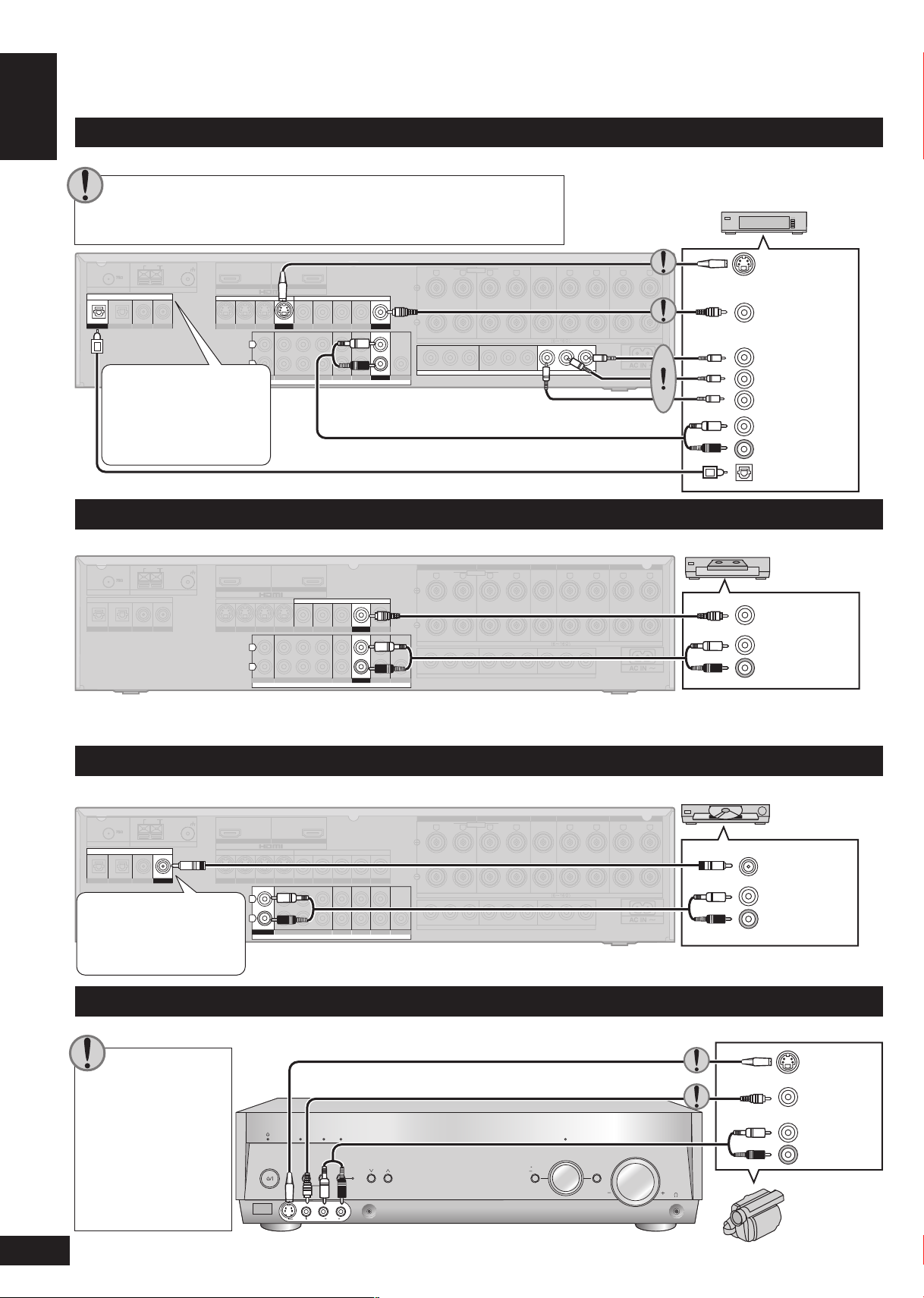
Home Theater connections
Connecting your television and DVD equipment (cont.)
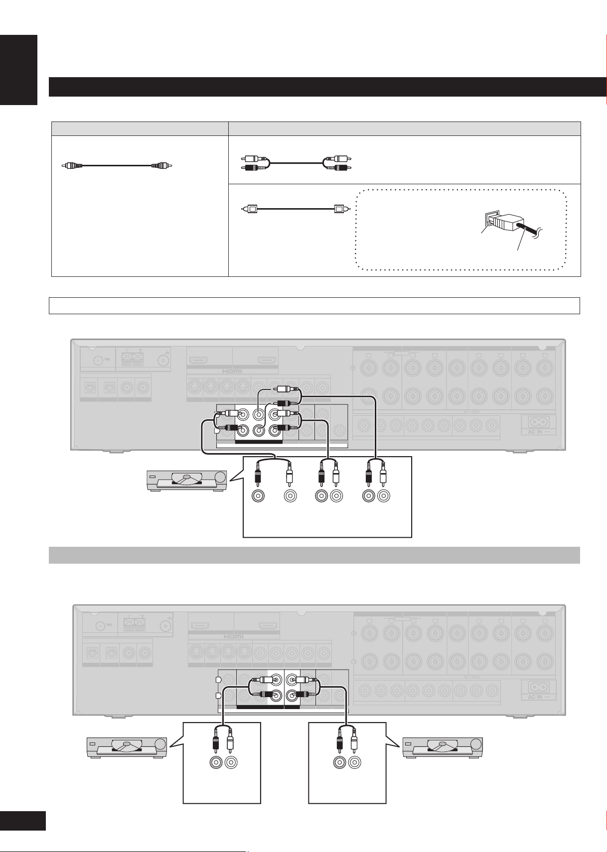
Connection cable
Video cable Audio cable
Video connection cable Stereo phono cable
White (L)
Red (R)
Home Theater connections
6-channel discrete connection (for high-quality DVD-Audio sound)
Optical fibre cable
Connecting the optical digital cable
Note the shape and fit it
correctly into the terminal.
Do not bend!
Rear panel
DVD equipment
SUBWOOFER CENTER
(R) (L)
FRONT
(R) (L)
SURROUND
See also “Playing DVD-Audio”,
➡ page 20.
Analogue audio connections
There are some limitations on digital output from DVD equipment, so you may need to make this connection. For video connections,
➡ pages 6 and 7.
DVD player
(R) (L)
AUDIO
OUT
DVD recorder
(R) (L)
AUDIO
OUT
Rear panel
8
ENGLISH
RQTV0156
(TV/STB)
OPTICAL1
Y PB PR Y YPB PR PB PR
BI-WIRE
LF HF
DIGITAL IN
(DVD RECORDER)
(DVD PLAYER)
(CD)
OPTICAL2 COAXIAL1
COAXIAL2
OUT (DVD RECORDER) IN
S VIDEO
OUT
TV MONITORINDVD PLAYERINDVD RECORDERINTV/STB
OUT
VIDEO
TV MONITOR DVD PLAYER
IN IN
DVD RECORDERINVCRINTV/STB
L
R
IN
CD
CENTER
SUBWOOFER
SURROUND
FRONT
DVD/DVD 6CH IN
AUDIO
IN
DVD RECORDERINVCRINTV/STB
OUT
SUBWOOFER
LR
FRONT A FRONT BLRCENTER SURROUNDLRSURROUND BACK
LR
TV MONITOR OUT DVD RECORDER IN
COMPONENT VIDEO
TV / STB IN
LOOP EXTLOOP EXTLOOP EXT
AM ANTFM ANT
LOOP ANT
GND
SPEAKERS
(TV/STB)
OPTICAL1
Y PB PR Y YPB PR PB PR
BI-WIRE
LF HF
DIGITAL IN
(DVD RECORDER)
(DVD PLAYER)
(CD)
OPTICAL2 COAXIAL1
COAXIAL2
OUT (DVD RECORDER) IN
S VIDEO
OUT
TV MONITOR
IN
DVD PLAYER
IN
DVD RECORDERINTV/STB
OUT
VIDEO
TV MONITOR DVD PLAYER
IN IN
DVD RECORDERINVCRINTV/STB
L
R
IN
CD
CENTER
SUBWOOFER
SURROUND
FRONT
DVD/DVD 6CH IN
AUDIO
IN
DVD RECORDERINVCRINTV/STB
OUT
SUBWOOFER
LR
FRONT A FRONT BLRCENTER SURROUNDLRSURROUND BACK
LR
TV MONITOR OUT DVD RECORDER IN
COMPONENT VIDEO
TV / STB IN
SPEAKERS
LOOP EXTLOOP EXTLOOP EXT
AM ANTFM ANT
LOOP ANT
GND
Turn off all components before making any connections.
•
Peripheral equipment and cables sold separately unless
•
otherwise indicated.
To connect equipment, refer to the appropriate operating
•
instructions.
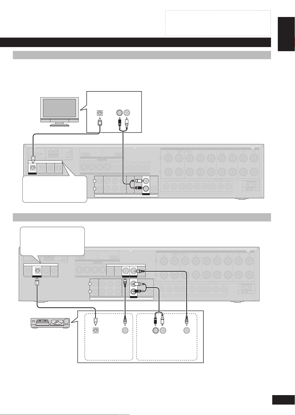
Playing audio from your television through speakers connected to this unit
Your equipment may be able to output both digital and analogue audio, so decide which best suits your needs.
To take advantage of the multi-channel sounds now available with digital television, use a digital connection. Read your television’s
operating instructions for details.
TV
DIGITAL
AUDIO OUT
(OPTICAL)
AUDIO OUT
(R) (L)
Digital input settings
You can change the input
settings for the digital terminals
if necessary (➡ page 28).
Connecting a combination DVD recorder/VCR
Digital input settings
You can change the input
settings for the digital terminals
if necessary (➡ page 28).
Rear panel
Home Theater connections
Rear panel
Combination DVD
recorder/VCR
DIGITAL
AUDIO OUT
(OPTICAL)
DVD OUT terminals
VIDEO
OUT
(R) (L)
AUDIO OUT
DVD/VHS COMMON OUT
terminals
VIDEO
OUT
For playback instructions,
➡ page 18.
9
ENGLISH
RQTV0156
AUTO
SPEAKER SETUP
ADVANCED
DUAL AMP
BI-AMP
SPEAKERS
A B
AUTO DETECTOR
SURROUND
AUX SETUP MIC
MENU
SETUP
RETURN
INPUT SELECTOR
ENTER
VOLUME
HDMI
TUNE
S VIDEO IN
VIDEO IN
L
A
U
D
IO
IN
R
(TV/STB)
OPTICAL1
Y PB PR Y YPB PR PB PR
BI-WIRE
LF HF
DIGITAL IN
(DVD RECORDER)
(DVD PLAYER)
(CD)
OPTICAL2 COAXIAL1
COAXIAL2
OUT (DVD RECORDER) IN
S VIDEO
OUT
TV MONITORINDVD PLAYERINDVD RECORDERINTV/STB
OUT
VIDEO
TV MONITOR DVD PLAYER
IN IN
DVD RECORDERINVCRINTV/STB
L
R
IN
CD
CENTER
SUBWOOFER
SURROUND
FRONT
DVD/DVD 6CH IN
AUDIO
IN
DVD RECORDERINVCRINTV/STB
OUT
SUBWOOFER
LR
FRONT A FRONT BLRCENTER SURROUND
LR
SURROUND BACK
LR
TV MONITOR OUT DVD RECORDER IN
COMPONENT VIDEO
TV / STB IN
LOOP EXTLOOP EXTLOOP EXT
AM ANTFM ANT
LOOP ANT
GND
SPEAKERS
(TV/STB)
OPTICAL1
Y PB PR Y YPB PR PB PR
BI-WIRE
LF
HF
DIGITAL IN
(DVD RECORDER)
(DVD PLAYER)
(CD)
OPTICAL2 COAXIAL1
COAXIAL2
OUT (DVD RECORDER) IN
S VIDEO
OUT
TV MONITORINDVD PLAYERINDVD RECORDERINTV/STB
OUT
VIDEO
TV MONITOR DVD PLAYER
IN IN
DVD RECORDERINVCRINTV/STB
L
R
IN
CD
CENTER
SUBWOOFER
SURROUND
FRONT
DVD/DVD 6CH IN
AUDIO
IN
DVD RECORDERINVCRINTV/STB
OUT
SUBWOOFER
LR
FRONT A FRONT BLRCENTER SURROUNDLRSURROUND BACK
LR
TV MONITOR OUT DVD RECORDER IN
COMPONENT VIDEO
TV / STB IN
LOOP EXTLOOP EXTLOOP EXT
AM ANTFM ANT
LOOP ANT
GND
SPEAKERS
(TV/STB)
OPTICAL1
Y PBPRY Y
Y
PBP
R
PBP
R
BI-WIRE
LF HF
DIGITAL IN
(DVD RECORDER)
(DVD PLAYER)
(CD)
OPTICAL2 COAXIAL1
COAXIAL2
OUT (DVD RECORDER) IN
S VIDEO
OUT
TV MONITORINDVD PLAYERINDVD RECORDER
IN
TV/STB
OUT
VIDEO
TV MONITOR DVD PLAYER
IN IN
DVD RECORDER
IN
VCRINTV/STB
L
R
IN
CD
CENTER
SUBWOOFER
SURROUND
FRONT
DVD/DVD 6CH IN
AUDIO
IN
DVD RECORDERINVCRINTV/STB
OUT
SUBWOOFER
LR
FRONT A FRONT BLRCENTER SURROUND
LR
SURROUND BACK
LR
TV MONITOR OUT DVD RECORDER IN
COMPONENT VIDEO
TV / STB IN
LOOP EXTLOOP EXTLOOP EXT
AM ANTFM ANT
LOOP ANT
GND
SPEAKERS
Y
PB
PR
Connecting other equipment
Connecting a set top box (cable or satellite)
Your equipment may be able to output both digital and analogue audio, so decide which best suits your needs.
Connect the video cables in sets so that you have the same type for
•
input from the equipment and output to your television.
For television connections, ➡ pages 6 and 7.
•
Cable box or satellite receiver etc.
Rear panel
S-VIDEO OUT
VIDEO OUT
Digital input settings
VIDEO OUT
You can change the input
COMPONENT
settings for the digital
terminals if necessary
(➡ page 28).
Connecting other equipment
(L)
AUDIO
OUT
(R)
DIGITAL AUDIO
OUT (OPTICAL)
Connecting a VCR
Rear panel
VCR
VIDEO OUT
(L)
AUDIO
OUT
(R)
Note that you must also use matching connections for your television and DVD recorder, “Connections for standard-resolution video”,
➡ page 7, to view or record the images played on the VCR.
Connecting a CD player
Your equipment may be able to output both digital and analogue audio, so decide which best suits your needs.
CD Player
Digital input settings
You can change the input
settings for the digital
terminals if necessary
(➡ page 28).
Connecting a video camera or other portable device
Use these terminals for temporary connections.
Connect the video
10
•
cables in sets so that
you have the same
type for input from the
equipment and output
to your television.
For television
•
connections, ➡ pages
6 and 7.
DIGITAL AUDIO
OUT (COAXIAL)
(L)
AUDIO
OUT
(R)
Rear panel
S-VIDEO
OUT
VIDEO OUT
(L)
AUDIO
(R)
OUT
Video camera
etc.
ENGLISH
RQTV0156
(TV/STB)
OPTICAL1
DIGITAL IN
(DVD RECORDER)
(DVD PLAYER)
(CD)
OPTICAL2 COAXIAL1
COAXIAL2
OUT (DVD RECORDER) IN
S VIDEO
OUT
TV MONITOR
IN
DVD PLAYERINDVD RECORDERINTV/STB
OUT
VIDEO
TV MONITOR DVD PLAYER
IN IN
DVD RECORDERINVCRINTV/STB
L
R
IN
CD
CENTER
SUBWOOFER
SURROUND
FRONT
DVD/DVD 6CH IN
AUDIO
IN
DVD RECORDERINVCRINTV/STB
OUT
SUBWOOFER
SURROUNDLRSURROUND BACK
LR
LOOP EXTLOOP EXTLOOP EXT
AM ANTFM ANT
LOOP ANT
GND
1
2
FM ANT
1
3
2
Turn off all components before making any connections.
AUTO
SPEAKER SETUP
ADVANCED
DUAL AMP
BI-AMP
SPEAKERS
A B
AUTO DETECTOR
SURROUND
AUX SETUP MIC
MENU
SETUP
RETURN
INPUT SELECTOR
ENTER
VOLUME
HDMI
TUNE
S VIDEO IN
VIDEO IN
L
A
U
DI
O
IN
R
VOLUME
SPEAKERS
A B
•
Peripheral equipment and cables sold separately unless
•
otherwise indicated.
To connect equipment, refer to the appropriate operating
•
instructions.
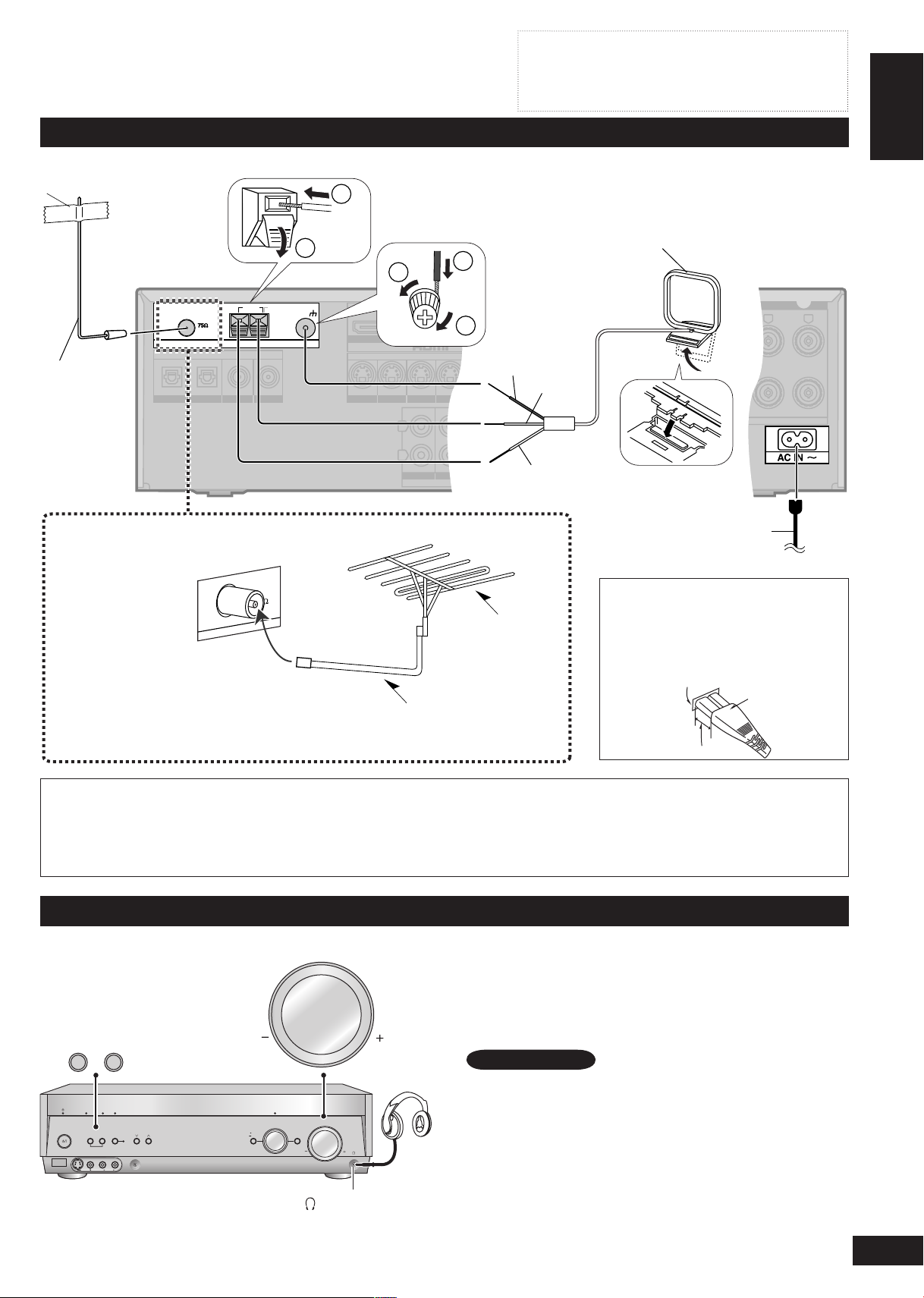
Connecting the antennas and AC mains lead
Adhesive tape
Rear panel
FM indoor
antenna
(included)
Fix the other
end of the
antenna
where
reception is
best.
FM outdoor antenna
(not included)
Disconnect the FM
•
indoor antenna.
The antenna
•
should be installed
by a competent
technician.
75 Ω coaxial cable
Connect AC mains lead after all other cables and cords are connected.
The included AC mains lead is for use with this unit only. Do not use it with other equipment.
•
Do not use an AC mains lead from other equipment.
•
If the unit is left unplugged for longer than two weeks, all settings will revert to the factory settings. Perform the settings again if
•
this occurs.
AM loop antenna (included)
Keep the antenna cord away from
DVD recorders, DVD players, and
other cords.
Black
Red
White
Insertion of connector
Even when the connector is perfectly
FM outdoor
antenna
inserted, depending on the type of inlet
used, the front part of the connector
may jut out as shown in the drawing.
However there is no problem using the
unit.
AC mains lead (included)
To household mains socket
Appliance inlet
Connector
Approx. 6 mm
Connecting other equipment
Using headphones
Press [SPEAKERS A] and [SPEAKERS B] to turn
1.
off the speakers.
Reduce the volume and connect the headphones.
2.
Plug type: 6.3 mm stereo (in diameter)
Adjust the volume.
3.
•
•
•
(Headphone jack)
Note
Avoid listening for prolonged periods of time to prevent hearing
damage.
Turning the speakers off automatically engages stereo play, and
when you play multi-channel sources they are down-mixed (2CH
MIX). (Some DVD-Audio prohibit down-mixing.)
Note that if you are using DVD 6CH input (➡ page 20), the input
source switches to “DVD” (2 channel) and only the sound for the
front speakers is output.
11
ENGLISH
RQTV0156
Speaker connections
Y PB PR Y YPB PR PB PR
BI-WIRE
LF HF
(CD)
COAXIAL2
OUT (DVD RECORDER) IN
S VIDEO
OUT
TV MONITORINDVD PLAYERINDVD RECORDERINTV/STB
OUT
VIDEO
TV MONITOR DVD PLAYER
IN IN
DVD RECORDERINVCRINTV/STB
L
R
IN
CD
CENTER
SUBWOOFER
SURROUND
FRONT
DVD/DVD 6CH IN
AUDIO
IN
DVD RECORDERINVCRINTV/STB
OUT
SUBWOOFER
LR
FRONT A FRONT BLRCENTER SURROUNDLRSURROUND BACK
LR
TV MONITOR OUT DVD RECORDER IN
COMPONENT VIDEO
TV / STB IN
LOOP
EXT
LOOP
EXT
LOOP
EXT
AM ANTFM ANT
LOOP ANT
GND
SPEAKERS
HF
HF
LF
LF
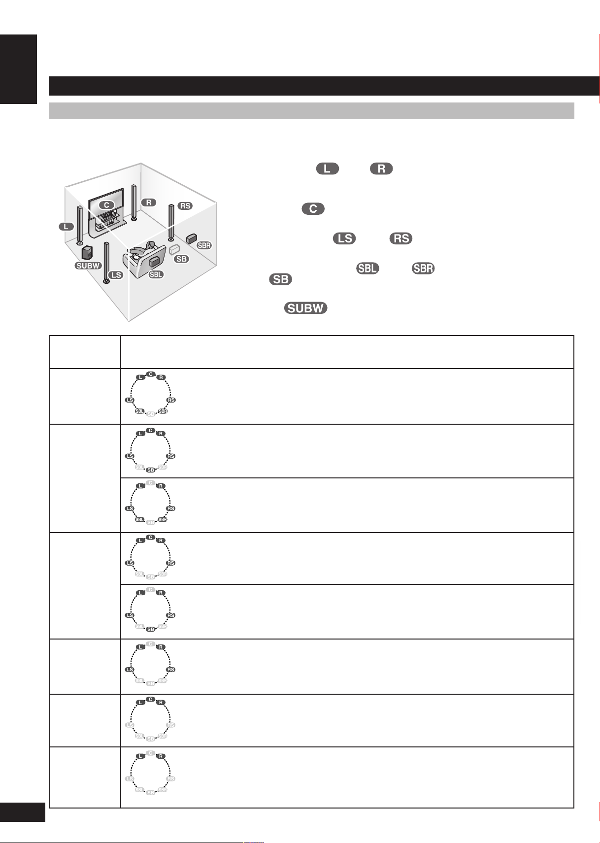
Connecting speakers
Connections and placement to suit the number of speakers you have
The ideal is to have all the speakers (except the subwoofer) at equal distances from the seating area.
Auto speaker setup compensates for any differences (➡ pages 14 to 16).
Front speakers (left , right )
Place either side of the television, then adjust their position and angle towards the
seating position until you are satisfied with the relationship between the images and
sound.
Center speaker ( )
Place directly above or below the center of the television, aiming at the seating position.
Surround speakers (left , right )
Speaker connections
Place on either side of or slightly behind the seating area, about one meter higher than
ear level.
Surround back speakers (left , right / when you connect only one
speaker )
Place behind the seating area, about one meter higher than ear level.
Subwoofer ( )
Place anywhere near the television (but not so close as to cause excessive vibration).
Number of
speakers
7
6
5
Placement
This setup is suitable for playing 6.1-channel sources (DTS-ES and Dolby Digital Surround EX).
•
Use Dolby Pro LogicΙΙx, DTS NEO:6, or SFC to enhance 2-channel or 5.1-channel sources.
•
This is the best setup for playing 6.1-channel sources (DTS-ES and Dolby Digital Surround EX).
•
Use Dolby Pro LogicΙΙx, DTS NEO:6, or SFC to enhance 2-channel or 5.1-channel sources.
•
Use this setup when you do not have a center speaker.
•
The center channel is split between the front speakers.
•
This is the best setup for playing 5.1-channel sources (Dolby Digital and DTS materials).
•
Use Dolby Pro LogicΙΙx, DTS NEO:6, or SFC to enhance 2-channel sources.
•
Use this setup when you do not have a center speaker.
•
The center channel is split between the front speakers.
•
12
4
3
2
Any center-channel sound (from 2-channel, 5.1-channel or 6.1-channel sources or allocated
•
by Dolby Pro LogicΙΙx, DTS NEO:6, or SFC) is split between the front speakers. Surround back
speakers are split between the surround speakers.
Any surround or surround back-channel sound (from multi-channel sources or allocated by
•
Dolby Pro LogicΙΙx, DTS NEO:6, or SFC) is split between the front speakers.
This is the best setup for stereo sources.
•
All other channels are “down-mixed” and played through the front speakers.
•