

Panasonic SA-XR57K, SA-XR57, SA-XR57S - AV Receiver Operating Instructions Manual
P PC
RQT8549-P
Dear customer
Thank you for purchasing this product.
Before connecting, operating or adjusting this product, please read
the instructions completely.
Please keep this manual for future reference.
As an ENERGY STAR® Partner∗,
Panasonic has determined that this
product meets the ENERGY STAR
®
guidelines for energy efficiency.
∗ For Canada only: The word “Participant” is
used in place of the word “Partner”.
If you have any questions contact
In the U.S.A.:1-800-211-PANA(7262)
In Canada:905-624-5505
For U.S.A. only
The warranty can be found on page 38.
For Canada only
The warranty can be found on page 39.
Operating Instructions
AV Control Receiver
Model No. SA-XR57
2
RQT8549
IMPORTANT SAFETY INSTRUCTIONS
Read these operating instructions carefully before using the unit. Follow the safety instructions on the unit and the applicable safety instructions listed
below. Keep these operating instructions handy for future reference.
1) Read these instructions.
2) Keep these instructions.
3) Heed all warnings.
4) Follow all instructions.
5) Do not use this apparatus near water.
6) Clean only with dry cloth.
7) Do not block any ventilation openings. Install in accordance with
the manufacturer’s instructions.
8) Do not install near any heat sources such as radiators, heat
registers, stoves, or other apparatus (including amplifiers) that
produce heat.
9) Do not defeat the safety purpose of the polarized or groundingtype plug. A polarized plug has two blades with one wider than the
other. A grounding-type plug has two blades and a third grounding
prong. The wide blade or the third prong are provided for your
safety. If the provided plug does not fit into your outlet, consult an
electrician for replacement of the obsolete outlet.
10) Protect the power cord from being walked on or pinched
particularly at plugs, convenience receptacles, and the point where
they exit from the apparatus.
11) Only use attachments/accessories specified by the manufacturer.
12) Use only with the cart, stand, tripod, bracket, or
table specified by the manufacturer, or sold with
the apparatus. When a cart is used, use caution
when moving the cart/apparatus combination to
avoid injury from tip-over.
13) Unplug this apparatus during lightning storms or when unused for
long periods of time.
14) Refer all servicing to qualified service personnel. Servicing is
required when the apparatus has been damaged in any way, such
as power-supply cord or plug is damaged, liquid has been spilled
or objects have fallen into the apparatus, the apparatus has been
exposed to rain or moisture, does not operate normally, or has
been dropped.
The lightning flash with arrowhead symbol, within
an equilateral triangle, is intended to alert the user
to the presence of uninsulated “dangerous voltage”
within the product’s enclosure that may be of
sufficient magnitude to constitute a risk of electric
shock to persons.
The exclamation point within an equilateral triangle
is intended to alert the user to the presence of
important operating and maintenance (servicing)
instructions in the literature accompanying the
appliance.
FCC Note:
This equipment has been tested and found to comply with the
limits for a Class B digital device, pursuant to Part 15 of the FCC
Rules. These limits are designed to provide reasonable
protection against harmful interference in a residential
installation. This equipment generates, uses and can radiate
radio frequency energy and, if not installed and used in
accordance with the instructions, may cause harmful interference
to radio communications. However, there is no guarantee that
interference will not occur in a particular installation. If this
equipment does cause harmful interference to radio or television
reception, which can be determined by turning the equipment off
and on, the user is encouraged to try to correct the interference
by one or more of the following measures:
• Reorient or relocate the receiving antenna.
• Increase the separation between the equipment and receiver.
• Connect the equipment into an outlet on a circuit different from
that to which the receiver is connected.
• Consult the dealer or an experienced radio/TV technician for
help.
Any unauthorized changes or modifications to this equipment
would void the user’s authority to operate this device.
This device complies with Part 15 of the FCC Rules. Operation is
subject to the following two conditions: (1) This device may not
cause harmful interference, and (2) this device must accept any
interference received, including interference that may cause
undesired operation.
Responsible Party:
Panasonic Corporation of North America
One Panasonic Way
Secaucus, NJ 07094
Telephone No.: 1-800-211-7262
THE FOLLOWING APPLIES ONLY IN THE U.S.A.
WARNING:
TO REDUCE THE RISK OF FIRE, ELECTRIC SHOCK OR
PRODUCT DAMAGE, DO NOT EXPOSE THIS APPARATUS
TO RAIN, MOISTURE, DRIPPING OR SPLASHING AND
THAT NO OBJECTS FILLED WITH LIQUIDS, SUCH AS
VASES, SHALL BE PLACED ON THE APPARATUS.
The socket outlet shall be installed near the equipment and easily
accessible.
The mains plug of the power supply cord shall remain readily
operable.
To completely disconnect this apparatus from the AC Mains,
disconnect the power supply cord plug from AC receptacle.
CAUTION
RISK OF ELECTRIC SHOCK
DO NOT OPEN
CAUTION: TO REDUCE THE RISK OF ELECTRIC
SHOCK, DO NOT REMOVE SCREWS.
NO USER-SERVICEABLE PARTS
INSIDE.
REFER SERVICING TO QUALIFIED
SERVICE PERSONNEL.
3
RQT8549
Connections
Basic operations
Before useOperationsReference
Table of contents
/
Listening caution
Selecting fine audio equipment such as the unit you’ve just purchased is
only the start of your musical enjoyment. Now it’s time to consider how
you can maximize the fun and excitement your equipment offers. This
manufacturer and the Electronic Industries Association’s Consumer
Electronics Group want you to get the most out of your equipment by
playing it at a safe level. One that lets the sound come through loud and
clear without annoying blaring or distortion-and, most importantly,
without affecting your sensitive hearing.
We recommend that you avoid prolonged exposure to excessive noise.
Sound can be deceiving. Over time your hearing “comfort level” adapts
to higher volumes of sound. So what sounds “normal” can actually be
loud and harmful to your hearing.
Guard against this by setting your equipment at a safe level BEFORE
your hearing adapts.
To establish a safe level:
• Start your volume control at a low setting.
• Slowly increase the sound until you can hear it comfortably and
clearly, and without distortion.
Once you have established a comfortable sound level:
• Set the dial and leave it there.
Taking a minute to do this now will help to prevent hearing damage or
loss in the future. After all, we want you listening for a lifetime.
Before use
IMPORTANT SAFETY INSTRUCTIONS
...............2
Listening caution ..............................................3
Control guide .................................................... 4
Connections
Home Theater connections
Connecting the unit to a TV, DVD recorder and DVD player
HDMI connections for enjoying high-quality sounds
and pictures easily.......................................................5
To enjoy high-quality pictures .................................................6
To enjoy standard-quality pictures ..........................................7
To enjoy analog sounds/To enjoy high-quality
analog sounds using DVD-Audio discs
(DVD analog 6-channel connections).....................................8
To enjoy TV sounds on multi channels
/
Connection to a DVD
recorder with built-in VCR.......................................................9
Connecting speakers
Placing and connecting speakers according to their numbers
.....10
Connecting speakers designed for bi-wiring.........................11
Connecting a second pair of front speakers .........................12
Making surround speakers wireless with SH-FX50/SH-FX60
...12
Connecting antennas.........................................................12
Connecting other equipment
Connecting the unit to a cable box or satellite receiver etc./
Connecting the unit to a VCR/Connecting the unit to a CD player/
Connecting the unit to a video camera or game player etc.
..... 13
Before playback
Detecting speakers automatically ......................... 14
Confirming audio output from speakers and adjusting volumes
.. 15
Basic
operations
Enjoying Home Theater features
Basic playback.........................................................16
Digital signals that can be played on this unit/
How the unit displays audio signals......................................17
Playback options
Using SPEAKERS B/ADVANCED DUAL AMP function/Enjoying
BI-AMP sounds/Playing DVD-Audio (Enjoying DVD-Audio sources
through digital connections/Playing DVD ANALOG 6CH/Enjoying
high quality 2-channel analog sounds)
....................................18
Using HDAVI Control
Enjoying Home Theater features through one-touch
operations ...........................................................................19
Setting the unit against HDAVI Control operations...............19
Remote controlling a TV or DVD recorder etc.
Remote controlling a TV ....................................................20
Remote controlling a DVD recorder..................................20
Remote controlling a DVD player......................................21
Remote controlling a VCR .................................................22
Remote controlling a CD player ........................................22
Changing remote control codes............................................23
Enter a code to operate some equipment ............................23
Operations
Listening to sounds with surround effects
Dolby Pro Logic /NEO:6 .....................................24
SFC (Sound Field Control)......................................25
Sound effect under remote control
Adjusting Dolby Pro Logic “MUSIC ” mode further/
Adjusting NEO:6’s “MUSIC
” mode further
/
Adjusting SFC (Sound Field Control) further ........................26
Convenient functions under remote control
Adjusting the subwoofer level/Silencing speakers temporarily/
Dimming the display light (Dimmer)......................................27
Using headphones..........................................27
Sound effect/Convenient functions
Basic operation........................................................28
Adjusting the bass/Adjusting the treble/Adjusting the volume
balance/Changing the audio output (Dual program)/Adjusting
the brightness of the display/Sleep timer..............................29
Setting the receiver
Basic operation....................................................... 30
Setting speakers and their sizes/Setting distances
/
Setting bi-wiring connections/Setting the lowpass filter ........31
Changing the digital input settings
/
Setting input signals
/
Making bi-amp settings (Adjusting the balance/Correcting the
HF and LF difference)...........................................................32
Selecting the equipment connected to the HDMI input terminal/
Reducing standby power consumption (power saving standby
mode)/Setting ADVANCED DUAL AMP functions off/Listening
comfortably at low volume/Switching the attenuator/Delaying
audio output and synchronizing it with video output/Returning
settings to conditions upon factory settings (Reset function)
..33
The radio
Manual tuning .....................................................................34
Preset tuning.......................................................................35
Presetting stations/Listening to preset stations ....................35
Reducing excessive noise ....................................................35
Reference
Troubleshooting guide ...................................36
Help message..................................................37
Specifications..................................................37
Warranty (U.S.A.) ............................................38
Warranty (Canada) ......................................... 39
Maintenance.................................................... 39
Supplied accessories ..................... Back cover
Product Service .............................. Back cover
x
x
EST. 1924
4
RQT8549
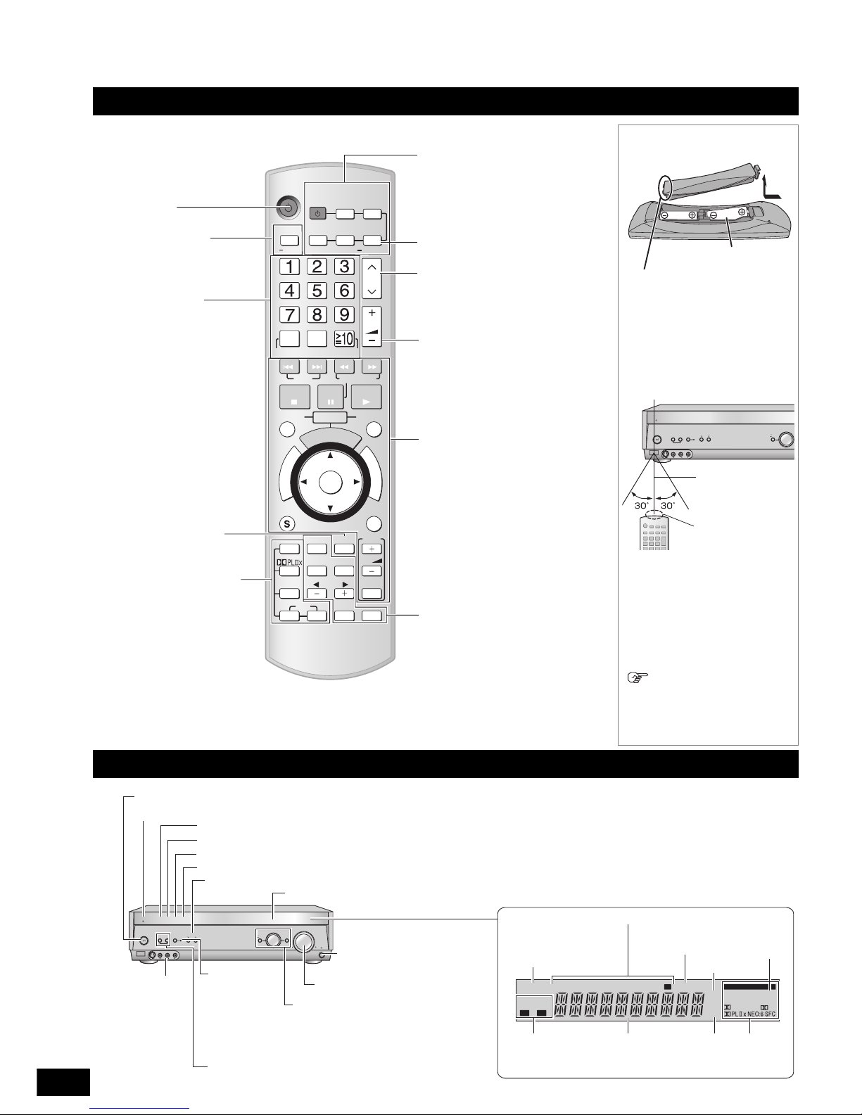
Control guide
Remote control
Batteries
• Insert so the poles (+ and –)
match those in the remote control.
• Do not use rechargeable type
batteries.
Use
Caution
• Do not place an object between the
signal sensor and the remote control.
• Do not place the signal sensor
under direct sunlight or the strong
light of an inverter fluorescent lamp.
• Keep the transmission window and
the unit’s sensor free from dust.
When you set the unit in
a cabinet
The remote controlling range may
decrease depending on the thickness
or colors of glass cabinet doors.
O
N
E
T
O
U
C
H
P
L
A
Y
D
I
R
E
C
T
N
A
V
I
G
A
T
O
R
T
O
P
M
E
N
U
F
U
N
C
T
I
O
N
S
0
RECEIVER
AV
SYSTEM
TV
RECORDER
DVD
DVD
PLAYER
ANALOG 6CH
VCRCD
TUNER
BAND
CH
VOLU ME
DIRECT TUNING
ENTER
SKIP
SLOW/SEARCH
STOP
PAU S E
PLAY
DRIVE SELECT
DVD RECORDER
CM SKIP
ENTER
SUB MENU RETURN
OFF
SUBWOOFER
TEST
TV
LEVEL
EFFECT
VOL
NEO : 6
SFC
MUSIC MOVIE
DIMMER MUTING
TV/VIDEO
DISC
Power button
For switching an input source
on and off/Source switching/
Switching remote control
modes (á pages 20 to 23)
For selecting a channel
TV (á page 20)
DVD recorder (á page 20)
VCR (á page 22)
TUNER (á page 35)
For adjusting volumes
(á page 15)
For operating other equipment
(á pages 19 to 23)
For adjusting the tone and
sound fields/Convenient
functions (á pages 26 and 27)
For listening to surround
sounds (á pages 24 and 25)
For playing DVD-Audio sources
on 6 channels (á page 18)
For inputting channels
TV (á page 20)
DVD recorder (á page 20)
VCR (á page 22)
For selecting a track or
chapter
DVD recorder (á page 20)
DVD player (á page 21)
For selecting a track
CD player (á page 22)
For inputting the station
frequency/For selecting a
channel
TUNER (á pages 34 and 35)
For adjusting speaker
volumes (á page 15)
For selecting an SFC
mode (á page 25)
For confirming audio
output from speakers
(á page 15)
For selecting tuner/
For switching FM or AM
(á page 34)
(R6/LR6, AA)
Open by pressing a lid edge.
Place this side in before the
other side when you close.
AUTO SPEAKER
DETECTOR
ADVANCED
DUAL AMP
BI-AMP
WIRELESS
READY
POWER
SPEAKERS
AB
AUTO SPEAKER
DETECTOR
MULTI CH
SURROUND
AUX
S VIDEO IN
VIDEO IN
L
A
U
DIO
IN
R
MENU
SETUP
RETURN
INPUT SELECTOR
HDMI
TUNE
Remote control signal sensor
7 meters (23 feet) (the
range varies
according to
transmission angles.)
Transmission
window
Unit and its display
AUTO SPEAKER
DETECTOR
ADVANCED
DUAL AMP
BI-AMP
WIRELESS
READY
POWER
SPEAKERS
AB
AUTO SPEAKER
DETECTOR
MULTI CH
SURROUND
AUX
S VIDEO IN
VIDEO IN
L
AU
DI
O
I
N
R
MENU
SETUP
RETURN
INPUT SELECTOR
ENTER
VOLUME
HDMI
TUNE
A B
2CH MIX
SPEAKERS
BI-WIRE
TUNED
MONO ST
SLEEP
PCM
inft
DTS 96/24DTS
-ES
DIGITAL EX
EX
M
DIGITAL INPUT
kHz
MHz
Flashes when automatic speaker detection is on (á page 14)
Lights up when advanced dual amp is on (á
page 18)
Lights up when bi-amp is on (á page 18)
Lights up when you establish HDMI connections (á page 5)
For selecting front speakers (á pages 14 to 16, 18 and 27)
For switching the
multi-channel
surround function
on and off (lights
up when the
function is on)
(
á
page 16)
For connecting
a video camera
etc. (á page 13)
For connecting a
headphone (á page 27)
For adjusting volumes (á pages 16 and 27)
For switching input sources (á page 16)
For operations in the menu or the
setup
Lights up when
2-channel mix is
functioning
Unit display
Lights up
when PCM FIX
is selected
Displays front
speakers in
use
General
display
Frequency
unit
indicators
Input signals for
digital sounds
(
á
page 17)
Lights up when the digital transceiver is in (á page 12)
Standby indicator [^]
When the unit is connected to the AC mains supply, this indicator lights up in standby mode and goes out when the unit is turned on.
Radio display
Sleep timer
indicator
[8, POWER]
Press to switch the unit from on to standby mode or vice versa. In standby mode, the unit is still consuming a small amount of power.
For tuning the radio and selecting preset stations (á pages 34 and 35)
5
RQT8549
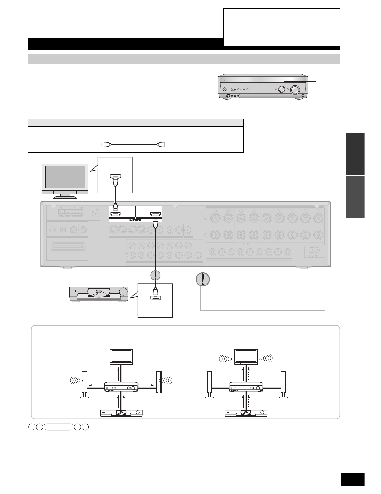
Home Theater connections
HDMI stands for High-Definition Multimedia Interface.
• HDMI enables you to transmit digital audio and video signals using a single cable.
You can also transmit control signals using HDMI connections (
á page 19).
• HDMI enables you to digitally transmit multi-channel sounds in DVD-Audio.
• The [HDMI] indicator stays on while you enjoy sounds and pictures through
HDMI connections.
Connection cable (All cables are sold separately)
• Make connections instructed in “To enjoy high-quality analog
sounds using DVD-Audio discs (DVD analog 6-channel
connections)” (á page 8) and perform DVD analog 6-channel
playback (á page 18) when the DVD recorder or DVD player
you connected is unable to make digital output of multichannel sounds in DVD-Audio (e.g. HDMI Ver. 1.0 equipment).
• You can enjoy Home Theater features easily by pressing [ONE
TOUCH PLAY] on this unit’s remote control when you connect the
unit through HDMI to a Panasonic TV (VIERA) or DVD recorder
(DIGA) available for HDAVI Control operations (
á page 19).
• The audio signal transmitted through HDMI takes priority
when you use both HDMI and digital terminals (á pages 6 and
7) for connection.
Connecting the unit to a TV, DVD recorder and DVD player
HDMI connections for enjoying high-quality sounds and pictures easily
Video and Audio cable
We advise you to use a cable that is
5 meters (16.4 feet) long or shorter
for HDMI connections in order to
stabilize operations and prevent
deterioration in picture quality.
HDMI Cable (It is recommended that you use Panasonic’s HDMI cable.)
[Recommended part number: RP-CDHG15 (1.5 m), RP-CDHG30 (3.0 m), RP-CDHG50 (5.0 m) etc.]
AUTO SPEAKER
DETECTOR
ADVANCED
DUAL AMP
BI-AMP
WIRELESS
READY
POWER
SPEAKERS
AB
AUTO SPEAKER
DETECTOR
MULTI CH
SURROUND
AUX
S VIDEO IN
VIDEO IN
L
A
U
DIO
IN
R
MENU
SETUP
RETURN
INPUT SELECTOR
ENTER
VOLUME
HDMI
TUNE
[HDMI]
(TV/STB)
OPTICAL1
YPB PR YYPB PR PB PR
BI-WIRE
LF HF
LOOP EXT
GND
LOOP EXT
GND
LOOP EXT
GND
DIGITAL IN
AM ANTFM ANT
LOOP ANT
GND
(DVD RECORDER)
(DVD PLAYER)
(CD)
OPTICAL2 COAXIAL1
COAXIAL2
DIGITAL TRANSCEIVER
SURROUND CHANNEL
OUT (DVD RECORDER) IN
S VIDEO
OUT
TV MONITORINDVD PLAYERINDVD RECORDERINTV/STB
OUT
VIDEO
TV MONITOR DVD PLAYER
IN IN
DVD RECORDERINVCRINTV/STB
L
R
IN
CD
CENTER
SUBWOOFER
SURROUND
FRONT
DVD/DVD 6CH IN
AUDIO
IN
DVD RECORDERINVCRINTV/STB
OUT
SUBWOOFER
LR
FRONT AFRONT
BLRCENTER SURROUNDLRSURROUND BACK
LR
SPEAKERS
TV MONITOR OUT DVD RECORDER IN
COMPONENT VIDEO
TV / STB IN
HAUT-PARLEURS
TV
Change the choice to “DVD ” in “Selecting the
equipment connected to the HDMI input
terminal” (á page 33)
when you connect the
unit to a DVD player.
TV HDMI
(AV IN)
DVD HDMI
(AV OUT)
The unit’s rear view
DVD recorder or
DVD player
• Make additional connections
instructed on page 9 for enjoying
TV sounds on multi channels.
When this
unit is on
When this
unit is off
Video
Audio
Audio
How audio and video signals flow when you make HDMI connections
Audio and video signals travel from the DVD recorder or DVD player to the TV by way of this unit even when the unit is off (the
standby through function).
TV
This unit
DVD recorder or DVD player
TV
This unit
DVD recorder or DVD player
AudioVideo AudioVideo
AudioVideo
Speakers Speakers
Note
Control guide/Home Theater connections
Connections
Before use
• Turn off all components before making any
connections.
• Peripheral equipment sold separately unless
otherwise indicated.
• To connect equipment, refer to the appropriate
operating instructions.
6
RQT8549
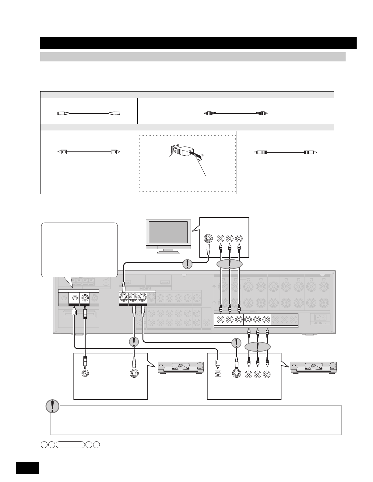
Connection cable (All cables are sold separately)
• Check terminals on your TV, DVD recorder or DVD player and obtain corresponding connection cables.
• Select one and use it for connection when your TV, DVD recorder or DVD player has two or more video terminals. The component
video terminal can produce more accurate colors than the S video terminal.
See page 13 for connecting the unit to a cable box or satellite receiver.
Connecting the unit to a TV, DVD recorder and DVD player
To enjoy high-quality pictures
Video cable
S-VIDEO connection cable Video connection cable
Audio cable
Optical fiber cable Coaxial cable
Insert the cable after
making sure shapes
match.
How to connect the optical fiber
cable
• Do not sharply bend the optical
fiber cable.
(TV/STB)
OPTICAL1
YPB PR Y YPB PR PB PR
BI-WIRE
LF
HF
LOOP EXT
GND
LOOP EXT
GND
LOOP EXT
GND
DIGITAL IN
AM ANTFM ANT
LOOP ANT
GND
(DVD RECORDER)
(DVD PLAYER)
(CD)
OPTICAL2 COAXIAL1
COAXIAL2
DIGITAL TRANSCEIVER
SURROUND CHANNEL
OUT (DVD RECORDER) IN
S VIDEO
OUT
TV MONITORINDVD PLAYERINDVD RECORDERINTV/STB
OUT
VIDEO
TV MONITOR DVD PLAYER
IN IN
DVD RECORDERINVCRINTV/STB
L
R
IN
CD
CENTER
SUBWOOFER
SURROUND
FRONT
DVD/DVD 6CH IN
AUDIO
IN
DVD RECORDERINVCRINTV/STB
OUT
SUBWOOFER
LR
FRONT AFRONT
BLRCENTER SURROUNDLRSURROUND BACK
LR
SPEAKERS
TV MONITOR OUT DVD RECORDER IN
COMPONENT VIDEO
TV / STB IN
HAUT-PARLEURS
YPB PR
Y
P
B
P
R
TV
The unit’s rear view
DVD player
DVD recorder
COMPONENT
VIDEO IN
S-VIDEO
IN
DIGITAL
AUDIO OUT
(COAXIAL)
S-VIDEO
OUT
DIGITAL
AUDIO OUT
(OPTICAL)
S-VIDEO
OUT
COMPONENT
VIDEO OUT
Changing the digital input
settings
For example, you can connect
the unit to a DVD player that
makes optical output only by
performing the steps instructed
in “Changing the digital input
settings” (á page 32).
• Make additional connections instructed on page
9 for enjoying TV sounds on multi channels.
Points regarding video terminals
• The input video signal can be sent out through an output terminal of the same type only.
• The component video terminals (color-difference video terminal) outputs red (P
R), blue (PB), and luminance (Y) signals
separately. The terminals reproduces colors with greater accuracy for this reason.
Note
Home Theater connections
7
RQT8549
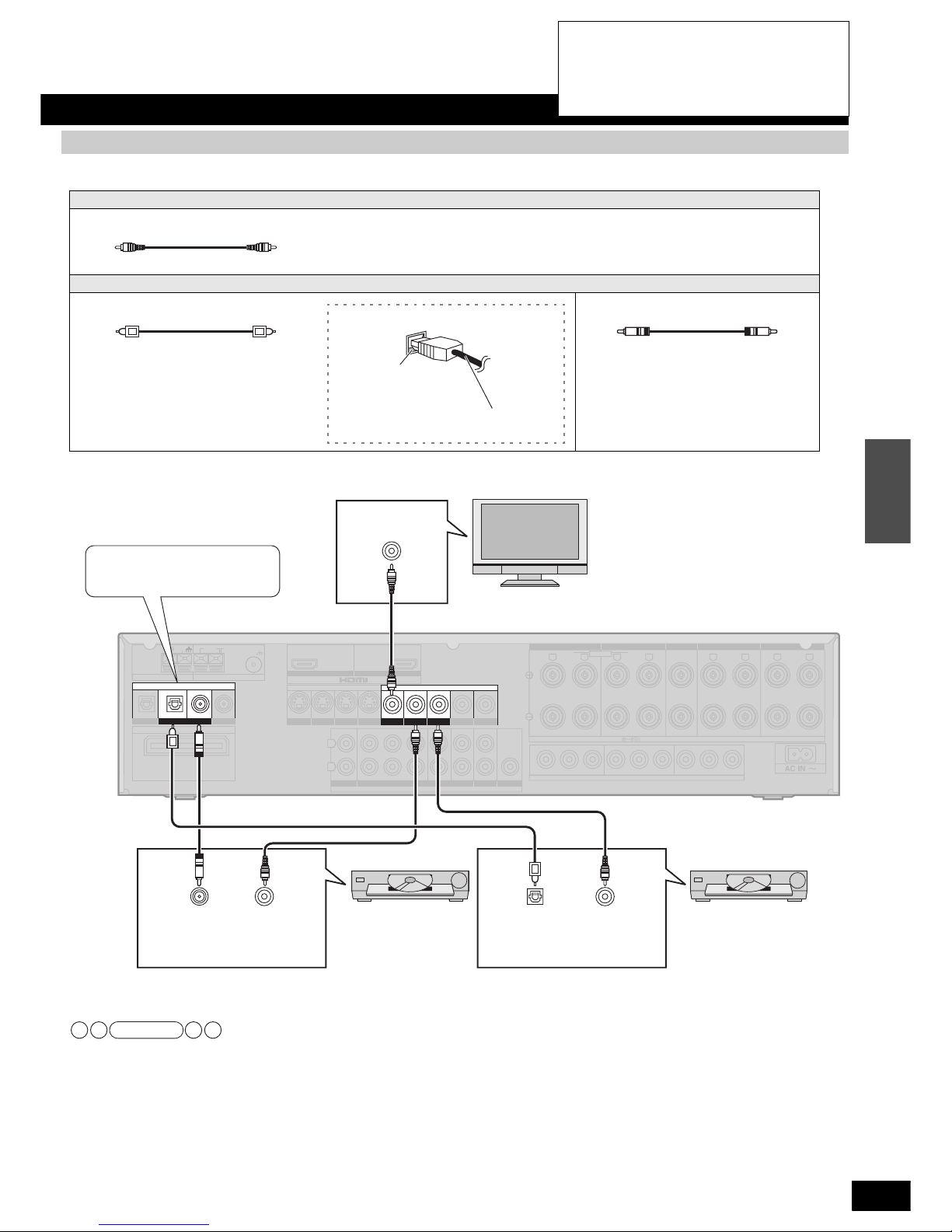
Connection cable (All cables are sold separately)
See page 13 for connecting the unit to a cable box or satellite receiver.
To enjoy standard-quality pictures
Video cable
Video connection cable
Audio cable
Optical fiber cable Coaxial cable
Insert the cable after
making sure shapes
match.
How to connect the optical fiber
cable
• Do not sharply bend the optical
fiber cable.
(TV/STB)
OPTICAL1
YPBPRYYPBP
R
PBP
R
BI-WIRE
LF
HF
LOOP EXT
GND
LOOP EXT
GND
LOOP EXT
GND
DIGITAL IN
AM ANTFM ANT
LOOP ANT
GND
(DVD RECORDER)
(DVD PLAYER)
(CD)
OPTICAL2 COAXIAL1
COAXIAL2
DIGITAL TRANSCEIVER
SURROUND CHANNEL
OUT (DVD RECORDER) IN
S VIDEO
OUT
TV MONITORINDVD PLAYERINDVD RECORDERINTV/STB
OUT
VIDEO
TV MONITOR DVD PLAYER
IN IN
DVD RECORDERINVCRINTV/STB
L
R
IN
CD
CENTER
SUBWOOFER
SURROUND
FRONT
DVD/DVD 6CH IN
AUDIO
IN
DVD RECORDERINVCRINTV/STB
OUT
SUBWOOFER
LR
FRONT AFRONT
BLRCENTER SURROUNDLRSURROUND BACK
LR
SPEAKERS
TV MONITOR OUT DVD RECORDER IN
COMPONENT VIDEO
TV / STB IN
HAUT-PARLEURS
“Changing the digital input
settings” (á page 32)
TV
VIDEO
IN
DIGITAL
AUDIO OUT
(COAXIAL)
DIGITAL
AUDIO OUT
(OPTICAL)
VIDEO
OUT
VIDEO
OUT
The unit’s rear view
• Make additional connections
instructed on page 9 for enjoying
TV sounds on multi channels.
DVD recorderDVD player
Note
Home Theater connections
Connections
• Turn off all components before making any
connections.
• Peripheral equipment sold separately unless
otherwise indicated.
• To connect equipment, refer to the appropriate
operating instructions.
8
RQT8549
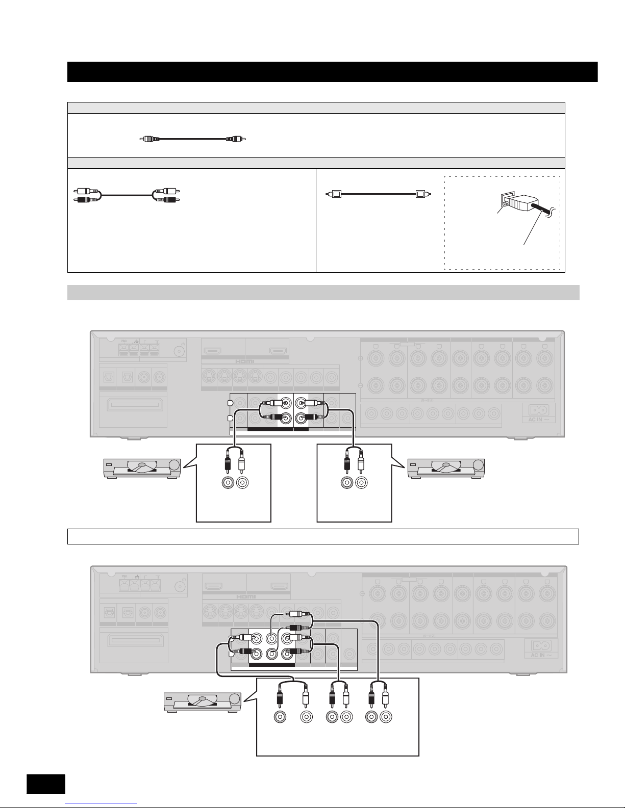
Connection cable (All cables are sold separately)
Make analog connections according to your equipment and preference. See pages 6 and 7 for video connections.
Connecting the unit to a TV, DVD recorder and DVD player
Video cable
Video connection cable
Audio cable
Stereo connection cable Optical fiber cable
White (L)
Red (R)
Insert the cable
after making sure
shapes match.
How to connect the optical
fiber cable
• Do not sharply bend the
optical fiber cable.
To enjoy analog sounds
(TV/STB)
OPTICAL1
YPB PR YYPB PR PB PR
BI-WIRE
LF
HF
LOOP EXT
GND
LOOP EXT
GND
LOOP EXT
GND
DIGITAL IN
AM ANTFM ANT
LOOP ANT
GND
(DVD RECORDER)
(DVD PLAYER)
(CD)
OPTICAL2 COAXIAL1
COAXIAL2
DIGITAL TRANSCEIVER
SURROUND CHANNEL
OUT (DVD RECORDER) IN
S VIDEO
OUT
TV MONITORINDVD PLAYERINDVD RECORDERINTV/STB
OUT
VIDEO
TV MONITOR DVD PLAYER
IN IN
DVD RECORDERINVCRINTV/STB
L
R
IN
CD
CENTER
SUBWOOFER
SURROUND
FRONT
DVD/DVD 6CH IN
AUDIO
IN
DVD RECORDERINVCRINTV/STB
OUT
SUBWOOFER
LR
FRONT AFRONT
BLRCENTER SURROUNDLRSURROUND BACK
LR
SPEAKERS
TV MONITOR OUT DVD RECORDER IN
COMPONENT VIDEO
TV / STB IN
HAUT-PARLEURS
(R) (L)
AUDIO OUT
(R) (L)
AUDIO OUT
DVD player DVD recorder
The unit’s rear view
To enjoy high-quality analog sounds using DVD-Audio discs (DVD analog 6-channel connections)
(TV/STB)
OPTICAL1
YPB PR YYPB PR PB PR
BI-WIRE
LF
HF
LOOP EXT
GND
LOOP EXT
GND
LOOP EXT
GND
DIGITAL IN
AM ANTFM ANT
LOOP ANT
GND
(DVD RECORDER)
(DVD PLAYER)
(CD)
OPTICAL2 COAXIAL1
COAXIAL2
DIGITAL TRANSCEIVER
SURROUND CHANNEL
OUT (DVD RECORDER) IN
S VIDEO
OUT
TV MONITORINDVD PLAYERINDVD RECORDERINTV/STB
OUT
VIDEO
TV MONITOR DVD PLAYER
IN IN
DVD RECORDERINVCRINTV/STB
L
R
IN
CD
CENTER
SUBWOOFER
SURROUND
FRONT
DVD/DVD 6CH IN
AUDIO
IN
DVD RECORDERINVCRINTV/STB
OUT
SUBWOOFER
LR
FRONT AFRONT
BLRCENTER SURROUNDLRSURROUND BACK
LR
SPEAKERS
TV MONITOR OUT DVD RECORDER IN
COMPONENT VIDEO
TV / STB IN
HAUT-PARLEURS
The unit’s rear view
DVD recorder or DVD player
(R) (L)
FRONT
CENTER
SUBWOOFER
• See page 18 for playback
instructions.
(R) (L)
SURROUND
Home Theater connections

9
RQT8549
Make the following connections in addition to those instructed on pages 5 to 7.
• Speakers produce sounds when you make connections for either digital audio (OPTICAL) output or analog audio output. Make
connections according to your equipment and preference.
• Use the optical fiber cable for connection when your TV has the digital output terminal.
To enjoy TV sounds on multi channels
(TV/STB)
OPTICAL1
YPB PR YYPB PR PB PR
BI-WIRE
LF
HF
LOOP EXT
GND
LOOP EXT
GND
LOOP EXT
GND
DIGITAL IN
AM ANTFM ANT
LOOP ANT
GND
(DVD RECORDER)
(DVD PLAYER)
(CD)
OPTICAL2 COAXIAL1
COAXIAL2
DIGITAL TRANSCEIVER
SURROUND CHANNEL
OUT (DVD RECORDER) IN
S VIDEO
OUT
TV MONITORINDVD PLAYERINDVD RECORDERINTV/STB
OUT
VIDEO
TV MONITOR DVD PLAYER
IN IN
DVD RECORDERINVCRINTV/STB
L
R
IN
CD
CENTER
SUBWOOFER
SURROUND
FRONT
DVD/DVD 6CH IN
AUDIO
IN
DVD RECORDERINVCRINTV/STB
OUT
SUBWOOFER
LR
FRONT AFRONT
BLRCENTER SURROUNDLRSURROUND BACK
LR
SPEAKERS
TV MONITOR OUT DVD RECORDER IN
COMPONENT VIDEO
TV / STB IN
HAUT-PARLEURS
TV
DIGITAL
AUDIO OUT
(OPTICAL)
AUDIO OUT
(R) (L)
The unit’s rear view
“Changing the digital input
settings” (á page 32)
Connection to a DVD recorder with built-in VCR
(TV/STB)
OPTICAL1
YPB PR YYPB PR PB PR
BI-WIRE
LF
HF
LOOP EXT
GND
LOOP EXT
GND
LOOP EXT
GND
DIGITAL IN
AM ANTFM ANT
LOOP ANT
GND
(DVD RECORDER)
(DVD PLAYER)
(CD)
OPTICAL2 COAXIAL1
COAXIAL2
DIGITAL TRANSCEIVER
SURROUND CHANNEL
OUT (DVD RECORDER) IN
S VIDEO
OUT
TV MONITORINDVD PLAYERINDVD RECORDERINTV/STB
OUT
VIDEO
TV MONITOR DVD PLAYER
IN IN
DVD RECORDERINVCRINTV/STB
L
R
IN
CD
CENTER
SUBWOOFER
SURROUND
FRONT
DVD/DVD 6CH IN
AUDIO
IN
DVD RECORDERINVCRINTV/STB
OUT
SUBWOOFER
LR
FRONT AFRONT
BLRCENTER SURROUNDLRSURROUND BACK
LR
SPEAKERS
TV MONITOR OUT DVD RECORDER IN
COMPONENT VIDEO
TV / STB IN
HAUT-PARLEURS
The unit’s rear view
“Changing the digital input
settings” (á page 32)
DVD recorder with
built-in VCR
DVD OUT terminals
DVD/VHS COMMON OUT terminals
DIGITAL
AUDIO OUT
(OPTICAL)
VIDEO
OUT
VIDEO
OUT
• See page 16 for playback
instructions.
(R) (L)
AUDIO OUT
Home Theater connections
Connections
• Turn off all components before making any
connections.
• Peripheral equipment sold separately unless
otherwise indicated.
• To connect equipment, refer to the appropriate
operating instructions.

10
RQT8549
Home Theater connections
The ideal placement is to set each speaker (excluding the subwoofer) the same distance away from the listening-viewing position.
Measure the actual distance from each of the connected speakers to the listening-viewing position and perform steps instructed in
“Setting distances” (á page 31) when you cannot install speakers the same distance away.
Front speakers (left , right )
Place on the left and right of the TV at seated ear height so that there is good coherency
between the picture and sound.
Center speaker ( )
Place underneath or above the center of the TV. Aim the speaker at the seating area.
Surround speakers (left , right )
Place on the side of or slightly behind the seating area, about one meter (3 feet) higher
than ear level.
Surround back speakers (left , right /when you connect one speaker only )
Place behind the seating area, about one meter (3 feet) higher than ear level.
Subwoofer ( )
The subwoofer can be placed in any position as long as it is at a reasonable distance from
the TV.
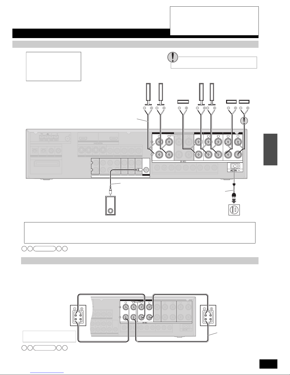
Connecting speakers
Placing and connecting speakers according to their numbers
The number of speakers
Placement
7 or 6
(including the
center speaker)
• This is a placement suited for playing 6.1-channel sources (DTS-ES and
Dolby Digital Surround EX materials).
• This placement offers 7.1/6.1-channel playback of 2-channel and
5.1-channel sources with the aid of Dolby Pro Logic , NEO: 6, and SFC
technology.
6 or 5
(excluding the
center speaker)
• This placement offers 6.1/5.1-channel playback without the center speaker.
• Sounds assigned to the center speaker are distributed to and output from
front speakers on the left and right.
5
(including the
center speaker)
• This is a placement suited for playing 5.1-channel sources (Dolby Digital
and DTS materials).
• This placement offers 5.1-channel playback of 2-channel sources with the
aid of Dolby Pro Logic , NEO: 6, and SFC technology.
4
(excluding the
center speaker)
• Sounds assigned to the center speaker come out of front speakers on the
left and right in a distributed manner when you use Dolby Pro Logic ,
NEO:6 and SFC on 2-channel sources and sources recorded on 5.1 and
more channels. Sounds assigned to surround back speakers are
distributed to and output from surround speakers on the left and right.
3
(including the
center speaker)
• Sounds assigned to surround and surround back speakers come out of
front speakers on the left and right in a distributed manner when you use
Dolby Pro Logic , NEO:6 and SFC on 2-channel sources and sources
recorded on 4.1 and more channels.
2
(excluding the
center speaker)
• This is a placement suited for playing 2-channel sources.
• Sounds assigned to all other speakers are consolidated and output from
front speakers on the left and right when you play multi-channel sources in
this arrangement.
x
x
x
x
How to connect speaker cables If using 4-mm plug
• Connect speaker cords properly to terminals after
making sure left and right, and “ ” and “ .” Improper
connections may cause the unit to develop problems.
•
Do not short-circuit speaker cords. The action may damage circuits.
Remove the vinyl
covering the tips
of speaker cords
by twisting it off.
Turn speaker terminals clockwise
and tighten them before inserting
plugs into their holes.
12
Speaker terminals
Note
( )
( )
11
RQT8549
Do not forget to take steps instructed in “Detecting speakers automatically” (á page 14) after connecting a new speaker or making a similar change.
Speakers designed for bi-wiring have separate connection terminals for high frequency and low frequency signals.
• Bi-wiring prevents high frequency and low frequency signals from interfering with each other. It offers playback in high audio quality.
• Different amplifiers for high frequency and low frequency signals produce bi-amp stereo sounds that are clearer and higher in audio
quality when you play sources containing analog audio and 2-channel PCM signals (á page 18).
• HF and LF stand for high frequencies and low frequencies, respectively.
• Make sure to connect speakers’ HF terminals with the unit’s FRONT B terminals, and speakers’ LF terminals with the unit’s FRONT A
terminals. “Correcting the HF and LF difference” (
á
page
32) becomes unavailable when you make reverse connections.
• Make sure to select “YES ” in “Setting bi-wiring connections” (
á
page
31) when you connect the unit to speakers designed for bi-
wiring. The speakers do not produce adequate sounds unless you make this setting.
(TV/STB)
OPTICAL1
YPB PR YYPB PR PB PR
LF HF
LOOP EXT
GND
LOOP EXT
GND
LOOP EXT
GND
DIGITAL IN
AM ANTFM ANT
LOOP ANT
GND
(DVD RECORDER)
(DVD PLAYER)
(CD)
OPTICAL2 COAXIAL1
COAXIAL2
DIGITAL TRANSCEIVER
SURROUND CHANNEL
OUT (DVD RECORDER) IN
S VIDEO
OUT
TV MONITORINDVD PLAYERINDVD RECORDERINTV/STB
OUT
VIDEO
TV MONITOR DVD PLAYER
IN IN
DVD RECORDERINVCRINTV/STB
L
R
IN
CD
CENTER
SUBWOOFER
SURROUND
FRONT
DVD/DVD 6CH IN
AUDIO
IN
DVD RECORDERINVCRINTV/STB
OUT
SUBWOOFER
LR
FRONT AFRONT
BLRCENTER SURROUNDLRSURROUND BACK
LR
SPEAKERS
TV MONITOR OUT DVD RECORDER IN
COMPONENT VIDEO
TV / STB IN
HAUT-PARLEURS
BI-WIRE
Household AC outlet
(AC 120 V, 60 Hz)
Connect AC power supply cord after all other cables and cords are connected.
• The included AC power supply cord is for use with this unit only. Do not use it with other equipment.
• Do not use an AC power supply cord from any other type of equipment with this unit.
• If the unit is left unplugged for longer than two weeks, all settings will revert to the factory settings. Perform the settings again if this occurs.
Speaker impedance
Front A: 6 to 8 Ω
Center: 6 to 8 Ω
Surround: 6 to 8 Ω
Surround back: 6 to 8 Ω
Front speakers
(R) (L)
Center
speaker
Surround speakers
(R) (L)
Surround back
speakers
(R) (L)
Active subwoofer
Speaker cable
The unit’s rear view
Use the terminal for the left speaker when you
connect one surround back speaker only.
Monaural connection cable
AC power
supply cord
(included)
Note
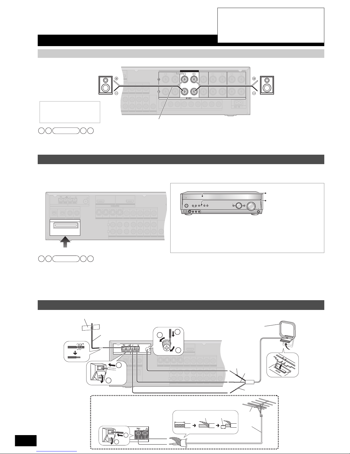
Connecting speakers designed for bi-wiring
YPB PR YYPB PR PB PR
BI-WIRE
LF
HF
VIDEO
DVD PLAYER
IN IN
DVD RECORDERINVCRINTV/STB
FRONT
AUDIO
IN
DVD RECORDERINVCRINTV/STB
OUT
SUBWOOFER
LR
FRONT AFRONT
BLRCENTER SURROUNDLRSURROUND BACK
LR
SPEAKERS
TV MONITOR OUT DVD RECORDER IN
COMPONENT VIDEO
TV / STB IN
HAUT-PARLEURS
HFHF
LF
LF
Speaker cable
Speaker impedance
BI-WIRE: 6 to 8 Ω
The unit’s rear view
Front speaker (L)
Rear view
Front speaker (R)
Rear view
Note
Home Theater connections
Connections
• Turn off all components before making any
connections.
• Peripheral equipment and cables sold separately
unless otherwise indicated.
• To connect equipment, refer to the appropriate
operating instructions.
12
RQT8549
Home Theater connections
Make the following connections when you wish to install a second pair of speakers in another room and enjoy music there.
• Select “SPEAKERS B” when you wish to enjoy sounds from speakers connected to the FRONT B terminals (á page 18).
• If you select SPEAKERS B only, playback is 2-channel. When a multi-channel source is played, the sounds intended for all the
speakers are played through the front left and front right speakers (2CH MIX).
You can connect left and right surround speakers wirelessly by using Panasonic SH-FX50/SH-FX60 (A set consisting of a digital transceiver and a wireless system (sold separately)) with the unit.
To use this option, insert the digital transceiver into the unit’s digital transceiver terminal and connect surround speakers to SH-FX50/SH-FX60’s
wireless system. See SH-FX50/SH-FX60’s operating instructions for details.
• Audio output changes as follows when you use surround speakers wirelessly.
- The maximum number of playback channels is 5.1. Surround back speakers become unavailable. Sounds assigned to them are
consolidated and output from surround speakers on the left and right.
- Left and right surround terminals on the unit make no audio output.
• Make sure to turn the unit off when you insert or remove the digital transceiver.
• “2-Way wireless” function of SH-FX60 cannot be used.
Connecting speakers
Connecting a second pair of front speakers
YPB PR YYPB PR PB PR
BI-WIRE
LF HF
VIDEO
IN IN
DVD RECORDERINVCRINTV/STB
FRONT
AUDIO
IN
DVD RECORDERINVCRINTV/STB
OUT
SUBWOOFER
LR
FRONT AFRONT
BLRCENTER SURROUNDLRSURROUND BACK
LR
SPEAKERS
TV MONITOR OUT DVD RECORDER IN
COMPONENT VIDEO
TV / STB IN
HAUT-PARLEURS
Speaker cable
The unit’s rear view
Front speaker (R) Front speaker (L)
Speaker impedance
Front A and B: 6 to 8 Ω
Front B: 6 to 8 Ω
Note
Making surround speakers wireless with SH-FX50/SH-FX60
The [WIRELESS READY] indicator stays on while the digital transceiver is in.
The indicator does not go on in the following cases:
The indicator stays off:
• When the [MULTI CH SURROUND] indicator is off
• When surround speakers are set as absent (á page 31)
The indicator flashes:
When radio waves are interrupted (when SH-FX50/SH-FX60 is off)
(TV/STB)
OPTICAL1
LOOP EXT
GND
LOOP EXT
GND
LOOP EXT
GND
DIGITAL IN
AM ANTFM ANT
LOOP ANT
GND
(DVD RECORDER)
(DVD PLAYER)
(CD)
OPTICAL2 COAXIAL1
COAXIAL2
DIGITAL TRANSCEIVER
SURROUND CHANNEL
OUT (DVD RECORDER) IN
S VIDEO
OUT
TV MONITORINDVD PLAYERINDVD RECORDERINTV/STB
OUT
VIDEO
TV MONITOR DVD PLAYER
IN IN
DVD RECORDERINVCRINTV/STB
L
R
IN
CD
CENTER
SUBWOOFER
SURROUND
FRONT
DVD/DVD 6CH IN
AUDIO
IN
DVD RECORDERINVCRINTV/STB
OUT
SUBWOOFER
The unit’s rear view
AUTO SPEAKER
DETECTOR
ADVANCED
DUAL AMP
BI-AMP
WIRELESS
READY
POWER
SPEAKERS
AB
AUTO SPEAKER
DETECTOR
MULTI CH
SURROUND
AUX
S VIDEO IN
VIDEO IN
L
A
U
DIO
IN
R
MENU
SETUP
RETURN
INPUT SELECTOR
ENTER
VOLUME
HDMI
TUNE
[MULTI CH SURROUND]
[WIRELESS READY]
Note
Connecting antennas
(TV/STB)
OPTICAL1
LOOP EXT
GND
LOOP EXT
GND
LOOP EXT
GND
DIGITAL IN
AM ANTFM ANT
LOOP ANT
GND
(DVD RECORDER)
(DVD PLAYER)
(CD)
OPTICAL2 COAXIAL1
COAXIAL2
DIGITAL TRANSCEIVER
SURROUND CHANNEL
OUT (DVD RECORDER) IN
S VIDEO
OUT
TV MONITORINDVD PLAYERINDVD RECORDERINTV/STB
OUT
VIDEO
TV MONITOR DVD PLAYER
IN IN
DVD RECORDERINVCRINTV/STB
L
R
IN
CD
CENTER
SUBWOOFER
SURROUND
FRONT
DVD/DVD 6CH IN
AUDIO
IN
DVD RECORDERINVCRINTV/STB
OUT
SUBWOOFER
1
2
1
3
FM ANT
GND
1
2
2
Adhesive tape
FM indoor antenna
(included)
Fix the other end of the
antenna where reception
is best.
AM loop antenna (included)
Keep the antenna cord away from DVD
recorders, DVD players, and other cords.
Black
Red
FM outdoor antenna (not included)
• Disconnect the FM indoor antenna.
• The antenna should be installed by a
competent technician.
• Twist the coaxial cable’s shield braid firmly
and connect it to the GND terminal.
20 mm (25/32" )
Shield braid
Core wire
10 mm (3/8")
FM outdoor
antenna
75 Ω
coaxial
cable
White
The unit’s rear view
• Turn off all components before making any
connections.
• Peripheral equipment and cables sold separately
unless otherwise indicated.
• To connect equipment, refer to the appropriate
operating instructions.
 Loading...