

Panasonic SA-XR50 User Manual
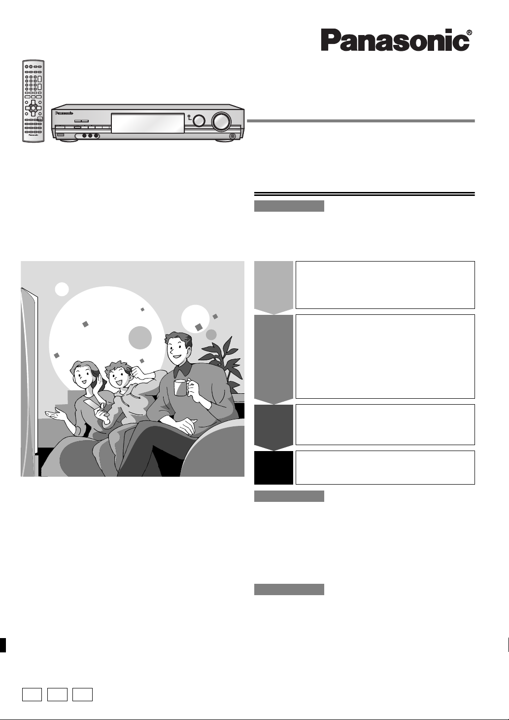
Operating Instructions
AV Control Receiver
Model No. SA-XR50
Dear customer
Thank you for purchasing this product.
Before connecting, operating or adjusting this product, please read these
instructions completely.
Please keep this manual for future reference.
Note:
“EB” on the packaging indicates the United Kingdom.
Table of contents
Before use
Caution for AC Mains Lead.................................................... 2
Safety precautions ................................................................. 2
Supplied accessories ............................................................ 3
The remote control ................................................................ 3
Step
Step
Step
Step
Home Theater connections....4
1
• DVD player • Speakers
• TV or monitor • AC mains lead
Other connections..................6
• DVD recorder/VCR • CD recorder
• TV or monitor • Tape deck
2
• Cable box or
satellite receiver
etc.
•CD player
• Video camera etc.
• Antennas
• Using speaker
terminal B
Settings..................................10
3
• Multi control basic • Adjusting speaker
setup settings output level
Basic operations...................12
4
• Sound modes
E EB
GN
Operations
Control guide ........................................................................ 14
The radio ............................................................................... 16
RDS broadcasts.................................................................... 18
Audio settings....................................................................... 19
Other functions..................................................................... 21
Making a recording............................................................... 21
Advanced setup.................................................................... 22
Reference
Specifications ....................................................................... 23
Troubleshooting guide.......................................... Back cover
Maintenance........................................................... Back cover
RQT7492-B

Caution for AC Mains Lead Safety precautions
(For United Kingdom)
(“EB” area code model only)
For your safety, please read the following text carefully.
This appliance is supplied with a moulded three pin mains plug for
your safety and convenience.
A 5-ampere fuse is fitted in this plug.
Should the fuse need to be replaced please ensure that the
Before use
replacement fuse has a rating of 5-ampere and that it is approved
by ASTA or BSI to BS1362.
Check for the ASTA mark or the BSI mark on the body of the fuse.
If the plug contains a removable fuse cover you must ensure that it
is refitted when the fuse is replaced.
If you lose the fuse cover the plug must not be used until a
replacement cover is obtained.
A replacement fuse cover can be purchased from your local dealer.
CAUTION!
IF THE FITTED MOULDED PLUG IS UNSUITABLE FOR
THE SOCKET OUTLET IN YOUR HOME THEN THE
FUSE SHOULD BE REMOVED AND THE PLUG CUT
OFF AND DISPOSED OF SAFELY.
THERE IS A DANGER OF SEVERE ELECTRICAL
SHOCK IF THE CUT OFF PLUG IS INSERTED INTO
ANY 13-AMPERE SOCKET.
If a new plug is to be fitted please observe the wiring code as stated
below.
If in any doubt please consult a qualified electrician.
IMPORTANT
The wires in this mains lead are coloured in accordance with the
following code:
Blue: Neutral, Brown: Live.
As these colours may not correspond with the coloured markings
identifying the terminals in your plug, proceed as follows:
The wire which is coloured Blue must be connected to the terminal
which is marked with the letter N or coloured Black or Blue.
The wire which is coloured Brown must be connected to the
terminal which is marked with the letter L or coloured Brown or Red.
WARNING: DO NOT CONNECT EITHER WIRE TO THE
EARTH TERMINAL WHICH IS MARKED WITH THE
LETTER E, BY THE EARTH SYMBOL OR
COLOURED GREEN OR GREEN/YELLOW.
THIS PLUG IS NOT WATERPROOF–KEEP DRY.
Before use
Remove the connector cover.
Placement
Set the unit up on an even surface away from direct sunlight, high
temperatures, high humidity, and excessive vibration. These conditions
can damage the cabinet and other components, thereby shortening the
unit’s service life.
Do not place heavy items on the unit.
Volt ag e
Do not use high voltage power sources. This can overload the unit and
cause a fire.
Do not use a DC power source. Check the source carefully when
setting the unit up on a ship or other place where DC is used.
AC mains lead protection
Ensure the AC mains lead is connected correctly and not damaged.
Poor connection and lead damage can cause fire or electric shock. Do not
pull, bend, or place heavy items on the lead.
Grasp the plug firmly when unplugging the lead. Pulling the AC mains
lead can cause electric shock.
Do not handle the plug with wet hands. This can cause electric shock.
Foreign matter
Do not let metal objects fall inside the unit. This can cause electric
shock or malfunction.
Do not let liquids get into the unit. This can cause electric shock or
malfunction. If this occurs, immediately disconnect the unit from the power
supply and contact your dealer.
Do not spray insecticides onto or into the unit. They contain flammable
gases which can ignite if sprayed into the unit.
Service
Do not attempt to repair this unit by yourself. If sound is interrupted,
indicators fail to light, smoke appears, or any other problem that is not
covered in these operating instructions occurs, disconnect the AC mains
lead and contact your dealer or an authorized service center. Electric
shock or damage to the unit can occur if the unit is repaired,
disassembled or reconstructed by unqualified persons.
Extend operating life by disconnecting the unit from the power source if
it is not to be used for a long time.
CAUTION!
Do not place anything on top of this unit or block the heat radiation
vents in any way. In particular, do not place tape decks or CD/DVD
players on this unit as heat radiated from it can damage your software.
How to replace the fuse
The location of the fuse differ according to the type of AC mains
plug (figures A and B). Confirm the AC mains plug fitted and follow
the instructions below.
Illustrations may differ from actual AC mains plug.
1. Open the fuse cover with a screwdriver.
Figure A
2. Replace the fuse and close or attach the fuse cover.
Figure A
Fuse
(5
ampere)
RQT7492
Figure
Figure
B
Fuse cover
B
Fuse
(5
2
ampere)
The socket outlet shall be installed near the equipment and
easily accessible or the mains plug or an appliance coupler
shall remain readily operable.
NORSK
Utstyret bør plasseres i nærheten av AC-stikkontakten, og
støpslet må være lett tilgjengelig hvis det skulle oppstå
problemer.
SUOMI
Laite tulee asettaa lähelle verkkopistorasiaa ja pistokkeen
täytyy olla sellaisessa asennossa, että siihen on helppo
tarttua ongelman sattuessa.
Manufactured under license from Dolby Laboratories.
“Dolby”, “Pro Logic” and the double-D symbol are trademarks of Dolby
Laboratories.
“DTS”, “DTS-ES”, “Neo:6” and “DTS 96/24” are trademarks of Digital
Theater Systems, Inc.
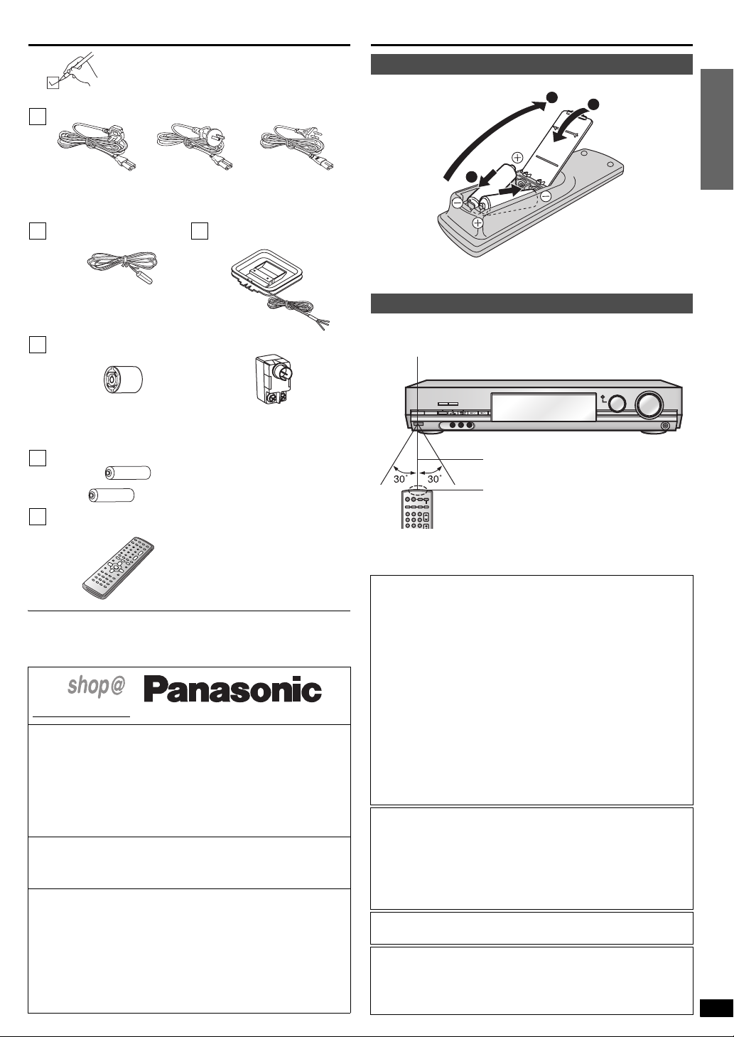
Supplied accessories
The remote control
Please check and identify the supplied accessories.
1 AC mains lead
For the United
Kingdom
(VJA0733)
1 FM indoor antenna
(RSA0007-L)
1 Antenna plug adapter
For the United Kingdom
(K1YZ02000013)
2 Batteries
For Australia and
New Zealand
(K2CJ2DA00010)
1 AM loop antenna
For Australia and New Zealand
(RFE0014)
For continental
Europe
(K2CQ2CA00002)
(RSA0037)
Batteries
1
3
2
(R6/LR6, AA, UM-3)
• Insert so the poles (+ and –) match those in the remote control.
• Do not use rechargeable type batteries.
Use
Aim at the sensor, avoiding obstacles, at a maximum range of 7 m directly
in front of the unit.
Remote control signal sensor
VOLUME
MULTI CONTROL
SPEAKERS
AB
^
POWER
8
6.1CH DECODING
VCR 2
AUDIO INLR
VIDEO IN
7 meters
INPUT SELECTOR
PUSH ENTER
DOWN UP
PHONES
Before use
1 Remote control
(EUR7722KC0)
Refer to the separate booklet,
“Remote Control Operation Guide”,
for remote control operation details.
Use the numbers indicated in parentheses when asking for replacement
parts.
For the United Kingdom and Republic of Ireland
www. panasonic.co.uk
(for UK customers only)
• Order accessory and consumable items for your product with ease
and confidence by telephoning our Customer Care Centre Mon-Friday
9:00am- 5:30pm. (Excluding public holidays.)
• Or go on line through our Internet Accessory ordering application.
• Most major credit and debit cards accepted.
• All enquiries transactions and distribution facilities are provided
directly by Panasonic UK Ltd.
• It couldn’t be simpler!
Customer Care Centre
For UK customers: 08705 357357
For Republic of Ireland customers: 01 289 8333
Technical Support
For UK customers: 0870 1 505610
This Technical Support Hot Line number is for Panasonic PC
software related products only.
For Republic of Ireland, please use the Customer Care Centre
number listed above for all enquiries.
For all other product related enquiries, please use the Customer
Care Centre numbers listed above.
RECEIVER
^ ^
CD
1
456
7 8 9
AV SYSTEM
TV
DVD
-
ANALOG 6CH
TAPE
DVD RECORDER
VCR
-
MONITOR
2 3
CH
VOLUME
Transmission window
• Keep the transmission window and the unit’s sensor free from dust.
• Operation can be affected by strong light sources, such as direct
sunlight, and the glass doors on cabinets.
CAUTION!
• DO NOT INSTALL OR PLACE THIS UNIT IN A
BOOKCASE, BUILT-IN CABINET OR IN ANOTHER
CONFINED SPACE. ENSURE THE UNIT IS WELL
VENTILATED. TO PREVENT RISK OF ELECTRIC SHOCK
OR FIRE HAZARD DUE TO OVERHEATING, ENSURE
THAT CURTAINS AND ANY OTHER MATERIALS DO NOT
OBSTRUCT THE VENTILATION VENTS.
• DO NOT OBSTRUCT THE UNIT’S VENTILATION
OPENINGS WITH NEWSPAPERS, TABLECLOTHS,
CURTAINS, AND SIMILAR ITEMS.
• DO NOT PLACE SOURCES OF NAKED FLAMES, SUCH
AS LIGHTED CANDLES, ON THE UNIT.
• DISPOSE OF BATTERIES IN AN ENVIRONMENTALLY
FRIENDLY MANNER.
WARNING:
TO REDUCE THE RISK OF FIRE, ELECTRIC SHOCK OR
PRODUCT DAMAGE, DO NOT EXPOSE THIS APPARATUS
TO RAIN, MOISTURE, DRIPPING OR SPLASHING AND
THAT NO OBJECTS FILLED WITH LIQUIDS, SUCH AS
VASES, SHALL BE PLACED ON THE APPARATUS.
THIS UNIT IS INTENDED FOR USE IN MODERATE
CLIMATES.
This product may receive radio interference caused by mobile
telephones during use. If such interference is apparent,
please increase separation between the product and the
mobile telephone.
RQT7492
3
U
D
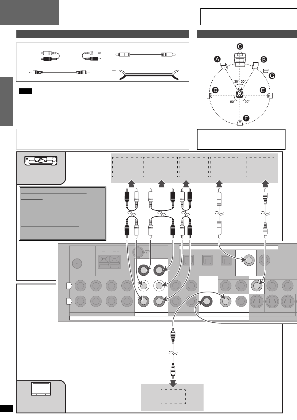
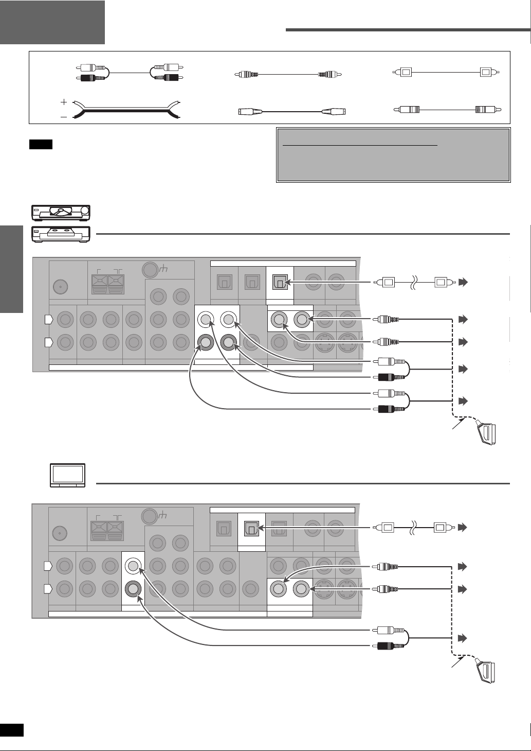
Step 1
Home Theater connections
DVD player/
TV or monitor
Before connecting
Stereo phono cable Coaxial cable
White (L)
Red (R)
Video connection cable Speaker cable
Turn off all components before making any connections.
Note
• Use a digital connection to enjoy Dolby Digital or DTS and record digital sources (á pages 12
and 21).
• Use an analogue connection to enjoy sources that cannot be decoded on this unit and to
Step 1
record analogue sources (á pages 12 and 21).
• Enjoy higher picture quality using the S VIDEO or COMPONENT terminal (á page 7).
• Refer to pages 6 through 9 regarding connections to other equipment.
FOR THE UNITED KINGDOM ONLY
READ THE CAUTION FOR THE AC MAINS LEAD ON PAGE 2 BEFORE
CONNECTION.
DVD player
Changing the digital input
settings
You can change the input settings for the digital
terminals if necessary. Note the equipment you
have connected to the terminals, then change
the settings (á page 10).
Note on analogue input
Connect to FRONT L, R if your DVD player
does not have 6 channel output.
111
AUDIO OUT
(SURROUND
L, R)
AUDIO OUT
(CENTER,
SUBWOOFER)
1
1
1
1
1
1
AUDIO OUT
(FRONT
L, R)
Placement of speakers
The front, center, and surround speakers
should be placed at approximately the same
distance from the seating area. The angles in
the diagram are approximate.
DIGITAL
AUDIO OUT
VIDEO OUT
TV or
RQT7492
4
monitor
75
Ω
FM ANT AM ANT
L
R
REC(OUT) PLAY(IN)
IN
CD
LOOP EXT
TAPE
LOOP ANT
GND
CENTER
SUBWOOFER
OUT
OPTICAL
SURROUND
IN
TV DVR/VCR1
FRONT
DVD/DVD 6CH
AUDIO
OUT IN
VIDEO IN
(TV) IN
OPTICAL1 OPTICAL2
SUBWOOFER
OUT
(DVR) IN
DVR/VCR1
OUT
MONITOR OUT
VIDEO
DIGITAL
TV
(DVD) IN
COAXIAL1
IN
IN
MONITOR OUT
IN
(CD) IN
COAXIAL2
DVD
YPB P
TV DVD
TV MONITOR O
IN IN
S VIDEO
Speakers/
AC mains lead
Peripheral equipment and cables sold separately unless otherwise indicated.
To connect equipment, refer to the appropriate operating instructions.
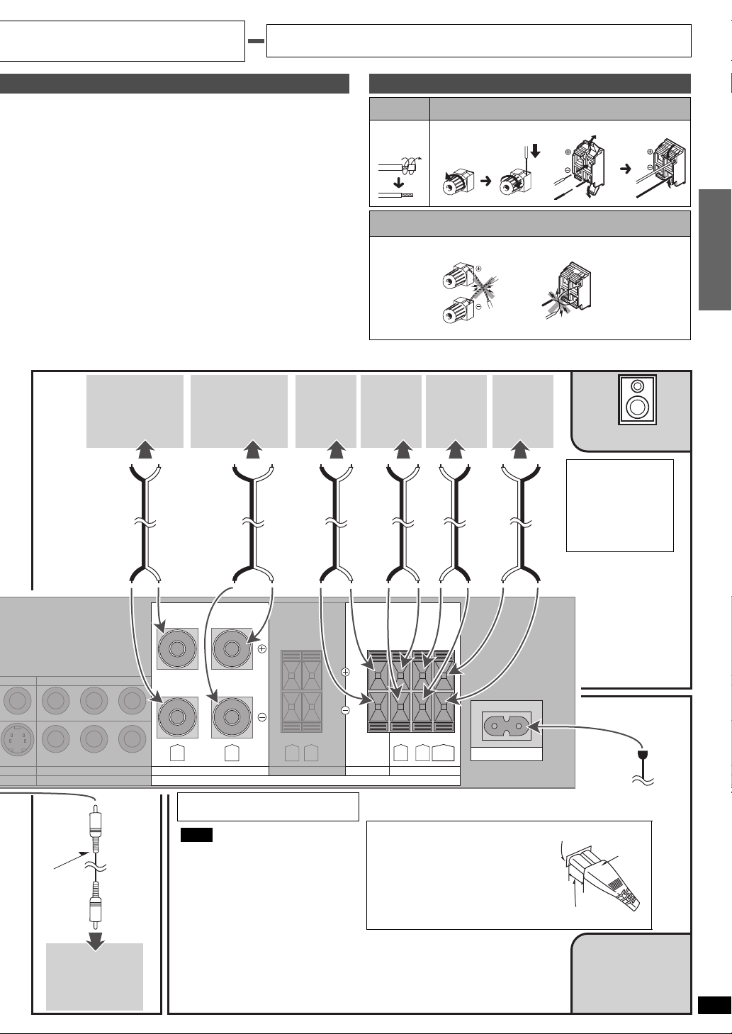
Connecting speakers
Front speakers ( left right)
Place on the left and right of the TV at seated ear height so that there is
good coherency between the picture and sound.
Center speaker ( )
Place underneath or above the center of the TV. Aim the speaker at the
seating area.
Surround speakers ( left right)
Place on the side of or slightly behind the seating area, about one meter
higher than ear level.
Surround back speaker ( )
Place behind the seating area, about one meter higher than ear level.
Subwoofer ( )
The subwoofer can be placed in any position as long as it is at a
reasonable distance from the TV.
Note that some experimentation can yield the smoothest low frequency
performance. Placement near a corner can increase the apparent
output level, but can result in unnatural bass.
Front
right
Front
left
Center
Cable Speaker terminals
Twist
FRONT A Other terminals
the wire
Note
Do not short-circuit.
Surround
right
Surround
left
Surround
back
Speakers
Speaker
Impedance:
Front A: 6-16 Ω
A and B:
Center: 6-16 Ω
Surround: 6-16 Ω
6-16 Ω
Step 1
UT
R
IN
DVR/VCR1
TV IN
B PR
YP
YPB PR
DVD IN
COMPONENT VIDEO
Monaural
connection
cable
Active
subwoofer
R L
FRONT A
Connect this lead after all other cables
and cords are connected.
Note
• The included AC mains lead is for use
with this unit only. Do not use it with
other equipment.
• If the unit is left unplugged for longer
than two weeks, all settings will revert
to the factory settings. Do the settings
again if this occurs.
R L
FRONT B CENTER SURROUND
SPEAKERS (6∼16Ω)
R L
BACK
Insertion of connector
Even when the connector is perfectly
inserted, depending on the type of
inlet used, the front part of the
connector may jut out as shown in the
drawing.
However there is no problem using the
unit.
AC IN
∼
To household
mains socket
Appliance inlet
Connector
Approx. 6 mm
AC mains lead
(included)
RQT7492
5
N
Step 2
Other connections
Stereo phono cable Video connection cable Optical fiber cable
White (L)
Red (R)
Speaker cable S-video connection cable Coaxial cable
Turn off all components before making any connections.
Note
• Do not sharply bend the optical fiber cable.
• Use a digital connection to enjoy Dolby Digital or DTS and record
digital source (á pages 12 and 21).
• Use an analogue connection to enjoy sources that cannot be decoded
on this unit and to record analogue sources (á pages 12 and 21).
DVD recorder/VCR
Step 2
75Ω
FM ANT AM ANT
L
R
REC(OUT)
IN
CD
LOOP EXT
PLAY(IN)
TAPE
IN
TV
CENTER
SURROUND
DVD/DVD 6CH
AUDIO
LOOP ANT
GND
SUBWOOFER
FRONT
OUT
OPTICAL
OUT IN
DVR/VCR1
Changing the digital input settings
You can change the input settings for the digital terminals if necessary.
Note the equipment you have connected to the terminals, then change
the settings (á page 10).
DIGITAL
(DVR) IN
(TV) IN
OPTICAL2
OPTICAL1 COAXIAL2
OUT
MONITOR OUT
OUT
SUBWOOFER
DVR/VCR1
TV
VIDEO
(DVD) IN
COAXIAL1
IN
(CD) IN
DVD
YP
IN
IN
MONITOR OUT
TV
TV DVD DVR/VCR1
TV MONITOR OUT
B PR
IN IN IN
S VIDEO
TV IN
B PR
YP
YPB PR
DVD IN
COMPONENT VIDEO
DIGITAL
AUDIO
OUT
VIDEO
OUT
VIDEO
IN
R
AUDIO
OUT
AUDIO
IN
FRO
21-pin scart cable connection also possible.
TV or monitor
(DVR) IN
OPTICAL2
DVR/VCR1
OUT
MONITOR OUT
VIDEO
DIGITAL
(CD) IN
DVD
YP
IN
IN
IN IN IN
MONITOR OUT
TV DVD DVR/VCR1
TV MONITOR OUT
B PR
S VIDEO
YP
YPB PR
TV
(DVD) IN
COAXIAL1
IN
21-pin scart cable connection also possible.
TV IN
B PR
DVD IN
COMPONENT VIDEO
DIGITAL
OUT
VIDEO
IN
VIDEO
OUT
R
AUDIO
OUT
FRON
CENTER
LOOP ANT
GND
SUBWOOFER
OUT
(TV) IN
OPTICAL COAXIAL2
OPTICAL1
75Ω
FM ANT AM ANT
LOOP EXT
L
R
REC(OUT)
IN
CD
TAPE
PLAY(IN)
IN
SURROUND
DVD/DVD 6CH
TV
AUDIO
RQT7492
FRONT
OUT IN
DVR/VCR1
OUT
SUBWOOFER
6

D
A
N
N
B
Peripheral equipment and cables sold separately unless otherwise indicated.
To connect equipment, refer to the appropriate operating instructions.
Cable box or satellite receiver etc.
CENTER
LOOP ANT
GND
SUBWOOFER
OUT
(TV) IN
OPTICAL OPTICAL2
OPTICAL1
75Ω
FM ANT AM ANT
LOOP EXT
L
R
REC(OUT)
IN
CD
TAPE
PLAY(IN)
IN
SURROUND
DVD/DVD 6CH
TV
AUDIO
FRONT
OUT IN
DVR/VCR1
SUBWOOFER
Enjoy even higher picture quality
S VIDEO
Use this connection for better picture quality than with the VIDEO
terminals.
n TV, monitor, cable box or satellite receiver etc.
(DVR) IN
DVR/VCR1
OUT
MONITOR OUT
VIDEO
(DVR) IN
DVR/VCR1
OUT
MONITOR OUT
VIDEO
DIGITAL
TV
DIGITAL
TV
(DVD) IN
COAXIAL1
IN
IN
(DVD) IN
COAXIAL1
IN
IN
(CD) IN
COAXIAL2
DVD
IN
MONITOR OUT
IN
MONITOR OUT
TV MONITOR OUT
YP
IN
TV
S VIDEO
(CD) IN
COAXIAL2
TV MONITOR OUT
DVD
YP
IN IN
TV DVR/VCR1
S VIDEO
BPR
DVD DVR/VCR1
BPR
DVD
LOOP ANT
GND
CENTER
SUBWOOFER
S-VIDEO OUT
S-VIDEO IN
FRONT
SURROUND
DVD/DVD 6CH
AUDIO
n DVD player
LOOP ANT
GND
CENTER
SUBWOOFER
S-VIDEO OUT
FRONT
SURROUND
DVD/DVD 6CH
AUDIO
OUT
OPTICAL
OUT IN
DVR/VCR1
OUT
OPTICAL
OUT IN
DVR/VCR1
(TV) IN
OPTICAL1 OPTICAL2
OUT
SUBWOOFER
(TV) IN
OPTICAL1 OPTICAL2
OUT
SUBWOOFER
OUT
IN IN
IN
DIGITAL
(DVR) IN
DVR/VCR1
OUT
MONITOR OUT
VIDEO
TV
(DVD) IN
COAXIAL1
IN
(CD) IN
COAXIAL2
DVD
YP
IN
IN
IN IN IN
MONITOR OUT
TV DVD DVR/VCR1
TV MONITOR OUT
B PR
S VIDEO
TV IN
B PR
YP
YPB PR
DVD IN
COMPONENT VIDEO
COMPONENT VIDEO
or
This connection provides high quality pictures by separating the
color (P
B and PR) and the luminance (Y) signals.
COMPONENT
Class 2 Wiring
VIDEO OUT (Y)
COMPONENT
TV IN
YP
BPR
BPR
YP
DVD IN FRONT B CENTER SURROUN
COMPONENT VIDEO
TV IN
YP
BPR
YPBP
DVD IN
COMPONENT VIDEO
R L
FRONT A
SPEAKERS (6∼8 ) HAUT-PARLEURS
R
R L
FRONT A
SPEAKERS (6∼8 ) HAUT-PARLEURS
VIDEO OUT (P
COMPONENT
VIDEO OUT (P
COMPONENT
R L
VIDEO IN (P
COMPONENT
VIDEO IN (P
COMPONENT
VIDEO IN (Y)
Class 2 Wiring
COMPONENT
VIDEO OUT (Y)
COMPONENT
VIDEO OUT (P
COMPONENT
VIDEO OUT (P
R L
FRONT B CENTER SURROU
DIGITAL
OUT
VIDEO
OUT
R
AUDIO
OUT
B)
R)
R L
R)
B)
B)
R)
R L
FRON
Step 2
B
B
n DVD recorder/VCR
(DVR) IN
DVR/VCR1
OUT
MONITOR OUT
VIDEO
DIGITAL
TV
(DVD) IN
COAXIAL1
IN
IN
COAXIAL2
DVD
IN
MONITOR OUT
(CD) IN
TV MONITOR OUT
BPR
YP
IN
TV
S VIDEO
IN
DVD
LOOP ANT
GND
CENTER
SUBWOOFER
(TV) IN
OUT
OPTICAL
OPTICAL1 OPTICAL2
S-VIDEO OUT
SURROUND
DVD/DVD 6CH
AUDIO
FRONT
OUT IN
DVR/VCR1
OUT
SUBWOOFER
Note
Video input can only be output again through the same type of terminal.
IN
DVR/VCR1
TV IN
YP
BPR
YPBP
DVD IN
COMPONENT VIDEO
Class 2 Wiring
R
R L
FRONT A
R L
FRONT B CENTER SURROU
SPEAKERS (6∼8 ) HAUT-PARLEURS
R L
RQT7492
7

N
N
N
SPEAKERS
A B
6.1CH DECODING
VIDEO IN
AUDIO INLR
VCR 2
^
Step 2
Other connections
Turn off all components before making any connections.
CD player
Step 2
75Ω
FM ANT AM ANT
L
R
REC(OUT)
IN
CD
75Ω
FM ANT AM ANT
L
R
REC(OUT) PLAY(IN)
IN
CD
LOOP EXT
PLAY(IN)
TAPE
LOOP EXT
TAPE
LOOP ANT
GND
CENTER
SUBWOOFER
IN
SURROUND
TV DVR/VCR1
DVD/DVD 6CH
AUDIO
FRONT
OUT IN
CD recorder
LOOP ANT
GND
CENTER
SUBWOOFER
IN
SURROUND
TV DVR/VCR1
DVD/DVD 6CH
AUDIO
FRONT
OUT IN
Tape deck
OUT
OPTICAL
OPTICAL
(TV) IN
(DVR) IN
OPTICAL1 OPTICAL2
OUT
SUBWOOFER
(TV) IN
OPTICAL1 OPTICAL2
OUT
SUBWOOFER
DVR/VCR1
OUT
MONITOR OUT
(DVR) IN
DVR/VCR1
OUT
MONITOR OUT
DIGITAL
TV
VIDEO
DIGITAL
TV
VIDEO
(DVD) IN
COAXIAL1
IN
IN
(DVD) INOUT
COAXIAL1
IN
IN
(CD) IN
COAXIAL2
DVD
IN
MONITOR OUT
DVD
IN
MONITOR OUT
TV MONITOR OUT
YP
B PR
IN IN IN
TV DVD DVR/VCR1
S VIDEO
(CD) IN
COAXIAL2
TV MONITOR OUT
YP
IN IN IN
TV DVD DVR/VCR1
S VIDEO
B PR
TV IN
B PR
YP
YPB PR
DVD IN
COMPONENT VIDEO
TV IN
B PR
YP
YPB PR
DVD IN
COMPONENT VIDEO
DIGITAL
OUT
LINE OUT
R
DIGITAL
DIGITAL IN
IN
R
FRO
FRO
(DVR) IN
DVR/VCR1
OUT
MONITOR OUT
VIDEO
DIGITAL
TV
(DVD) IN
COAXIAL1
IN
IN
(CD) IN
(CD) IN(DVD) IN
COAXIAL2
DVD
IN
MONITOR OUT
TV MONITOR OUT
YP
IN IN IN
TV DVD DVR/VCR1
S VIDEO
B PR
If you have a graphic equalizer,
connect it to the TAPE terminals.
TV IN
B PR
YP
YPB PR
DVD IN
COMPONENT VIDEO
REC (IN)
PLAY
(OUT)
R
FRO
75Ω
FM ANT AM ANT
L
R
REC(OUT)
IN
CD
LOOP EXT
PLAY(IN)
TAPE
LOOP ANT
GND
CENTER
SUBWOOFER
OUT
OUT
OPTICAL
IN
SURROUND
DVD/DVD 6CH
TV DVR/VCR1
AUDIO
FRONT
OUT IN
(TV) IN (DVR) IN
(TV) IN
OPTICAL1 OPTICAL2
OUT
SUBWOOFER
Video camera etc.
VIDEO
OUT
RQT7492
8
AUDIO
OUT
 Loading...