

Panasonic SA-XR10PP User Manual
PP
AV Control Receiver
Operating Instructions
Model No. SA-XR10
DVD
TUNER/
BAND
TOP MENU
MENU
DIGITAL
INPUT
SELECTOR
TV
VCR
RETURN
PAUSESTOP
SOUND MODE
CHANNEL VOLUME
PLAY
/SEARCH
SKIP
DISPLAY
MUTING
SUBWOOFER
SFC
ENTER
RECEIVER
RECEIVER
SLOW
Dear customer
Thank you for purchasing this product.
Before connecting, operating or adjusting this product, please read
these instructions completely.
Please keep this manual for future reference.
Table of contents
As an ENERGY STAR®Partner,
Panasonic has determined that this
product meets the ENERGY STAR
®
guidelines for energy efficiency.
Making a recording ....................................................20
Timer function ............................................................20
Other settings ............................................................21
Equipment connections
6
Speaker connections
5
Settings
8
Step 1
Basic operations
10
Before use
Reference
Step 2
Step 3
Step 4
Others
Operations
Control guide ..............................................................12
The radio ....................................................................18
Troubleshooting guide ..............................................22
The RESET function ..................................................22
Maintenance................................................................22
Specifications..............................................................23
Product Service ..........................................................23
Warranty (U.S.A.) ........................................................24
Customer Services Directory (U.S.A.) ......................24
IMPORTANT SAFETY INSTRUCTIONS ......................2
Listening caution..........................................................3
Supplied accessories ..................................................4
The remote control ......................................................4
RQT6501-Y
H0602RF0
En Cf
2
RQT6501
Before use
IMPORTANT SAFETY INSTRUCTIONS
The lightning flash with arrowhead symbol,
within an equilateral triangle, is intended to
alert the user to the presence of uninsulated
“dangerous voltage” within the product's
enclosure that may be of sufficient magnitude
to constitute a risk of electric shock to persons.
The exclamation point within an equilateral
triangle is intended to alert the user to the
presence of important operating and
maintenance (servicing) instructions in the
literature accompanying the appliance.
CAUTION:TO REDUCE THE RISK OF ELECTRIC
SHOCK, DO NOT REMOVE SCREWS.
NO USER-SERVICEABLE PARTS
INSIDE.
REFER SERVICING TO QUALIFIED
SERVICE PERSONNEL.
CAUTION
RISK OF ELECTRIC SHOCK
DO NOT OPEN
CAUTION:
This equipment has been tested and found to comply with
the limits for a Class B digital device, pursuant to Part 15 of
the FCC Rules.
These limits are designed to provide reasonable protection
against harmful interference in a residential installation. This
equipment generates, uses and can radiate radio frequency
energy and, if not installed and used in accordance with the
instructions, may cause harmful interference to radio
communications. However, there is no guarantee that
interference will not occur in a particular installation. If this
equipment does cause harmful interference to radio or
television reception, which can be determined by turning the
equipment off and on, the user is encouraged to try to
correct the interference by one or more of the following
measures:
¡Reorient or relocate the receiving antenna.
¡Increase the separation between the equipment and
receiver.
¡Connect the equipment into an outlet on a circuit different
from that to which the receiver is connected.
¡Consult the dealer or an experienced radio/TV technician
for help.
FCC Caution: To assure continued compliance, use only the
provided power supply cord with external mounted ferrite
core.
Any unauthorized changes or modifications to this
equipment would void the user’s authority to operate this
device.
This device complies with Part 15 of the FCC Rules.
Operation is subject to the following two conditions: (1) This
device may not cause harmful interference, and (2) this
device must accept any interference received, including
interference that may cause undesired operation.
THE FOLLOWING APPLIES ONLY IN THE U.S.A.
1) Read these instructions.
2) Keep these instructions.
3) Heed all warnings.
4) Follow all instructions.
5) Do not use this apparatus near water.
6) Clean only with dry cloth.
7) Do not block any ventilation openings. Install in
accordance with the manufacturer’s instructions.
8) Do not install near any heat sources such as radiators,
heat registers, stoves, or other apparatus (including
amplifiers) that produce heat.
9) Do not defeat the safety purpose of the polarized or
grounding-type plug. A polarized plug has two blades with
one wider than the other. A grounding-type plug has two
blades and a third grounding prong. The wide blade or the
third prong are provided for your safety. If the provided
plug does not fit into your outlet, consult an electrician for
replacement of the obsolete outlet.
10) Protect the power cord from being walked on or pinched
particularly at plugs, convenience receptacles, and the
point where they exit from the apparatus.
Read these operating instructions carefully before using the unit. Follow the safety instructions on the unit and the applicable safety
instructions listed below. Keep these operating instructions handy for future reference.
11) Only use attachments/accessories specified by the
manufacturer.
12) Use only with the cart, stand, tripod,
bracket, or table specified by the
manufacturer, or sold with the apparatus.
When a cart is used, use caution when
moving the cart/apparatus combination to
avoid injury from tip-over.
13) Unplug this apparatus during lightning storms or when
unused for long periods of time.
14) Refer all servicing to qualified service personnel. Servicing
is required when the apparatus has been damaged in any
way, such as power-supply cord or plug is damaged, liquid
has been spilled or objects have fallen into the apparatus,
the apparatus has been exposed to rain or moisture, does
not operate normally, or has been dropped.
3
RQT6501
Before use
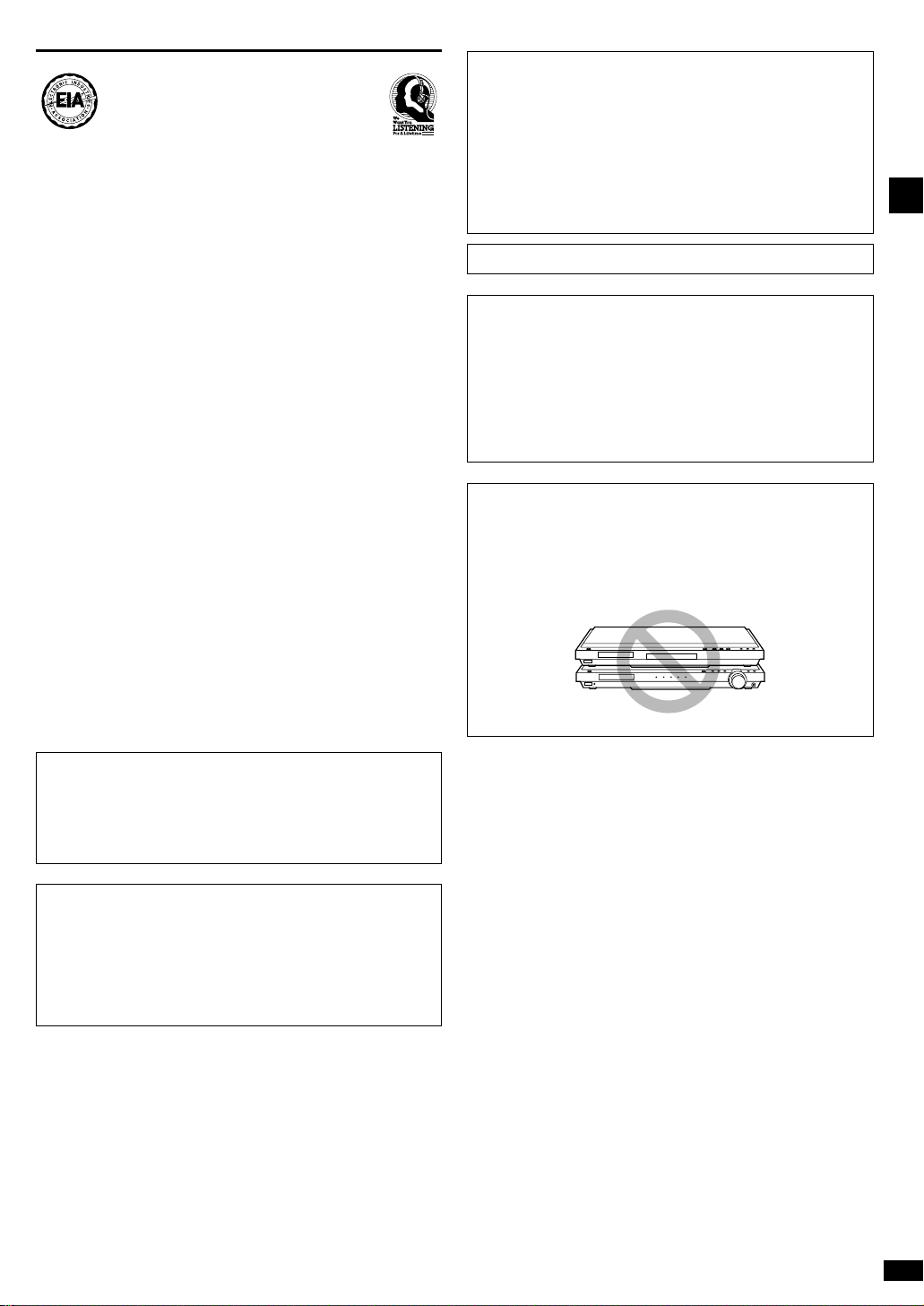
CAUTION
Do not place anything on top of this unit or block the heat
radiation vents in any way. In particular, do not place tape
decks or CD/DVD players on this unit as heat radiated from
it can damage your software.
DATE OF PURCHASE _____________________________
DEALER NAME __________________________________
DEALER ADDRESS _______________________________
________________________________________________
TELEPHONE NUMBER ____________________________
User memo:
The model number and serial number of this product can be found
on either the back or the bottom of the unit.
Please note them in the space provided below and keep for future
reference.
MODEL NUMBER
_______________________________________
SERIAL NUMBER
_______________________________________
SA-XR10
WARNING:
TO REDUCE THE RISK OF FIRE, ELECTRIC
SHOCK OR PRODUCT DAMAGE, DO NOT
EXPOSE THIS APPARATUS TO RAIN,
MOISTURE, DRIPPING OR SPLASHING AND
THAT NO OBJECTS FILLED WITH LIQUIDS,
SUCH AS VASES, SHALL BE PLACED ON
THE APPARATUS.
CAUTION!
DO NOT INSTALL, OR PLACE THIS UNIT, IN A
BOOKCASE, BUILT-IN CABINET OR IN ANOTHER
CONFINED SPACE. ENSURE THE UNIT IS WELL
VENTILATED. TO PREVENT RISK OF ELECTRIC SHOCK
OR FIRE HAZARD DUE TO OVERHEATING, ENSURE
THAT CURTAINS AND ANY OTHER MATERIALS DO
NOT OBSTRUCT THE VENTILATION VENTS.
Selecting fine audio equipment such as the unit you’ve just
purchased is only the start of your musical enjoyment. Now it’s
time to consider how you can maximize the fun and excitement
your equipment offers. This manufacturer and the Electronic
Industries Association’s Consumer Electronics Group want you
to get the most out of your equipment by playing it at a safe
level. One that lets the sound come through loud and clear
without annoying blaring or distortion–and, most importantly,
without affecting your sensitive hearing.
We recommend you to avoid prolonged exposure to excessive
noise.
Sound can be deceiving. Over time your hearing “comfort level”
adapts to higher volumes of sound. So what sounds “normal”
can actually be loud and harmful to your hearing.
Guard against this by setting your equipment at a safe level
BEFORE your hearing adapts.
To establish a safe level:
¡Start your volume control at a low setting.
¡Slowly increase the sound until you can hear it comfortably
and clearly, and without distortion.
Once you have established a comfortable sound level:
¡Set the dial and leave it there.
Taking a minute to do this now will help to prevent hearing
damage or loss in the future. After all, we want you listening for
a lifetime.
EST. 1924
Listening caution
Marking sign is located on bottom of the unit.
4
RQT6501
1
4
2
3
+
–
–
+
(R6, AA, UM-3)
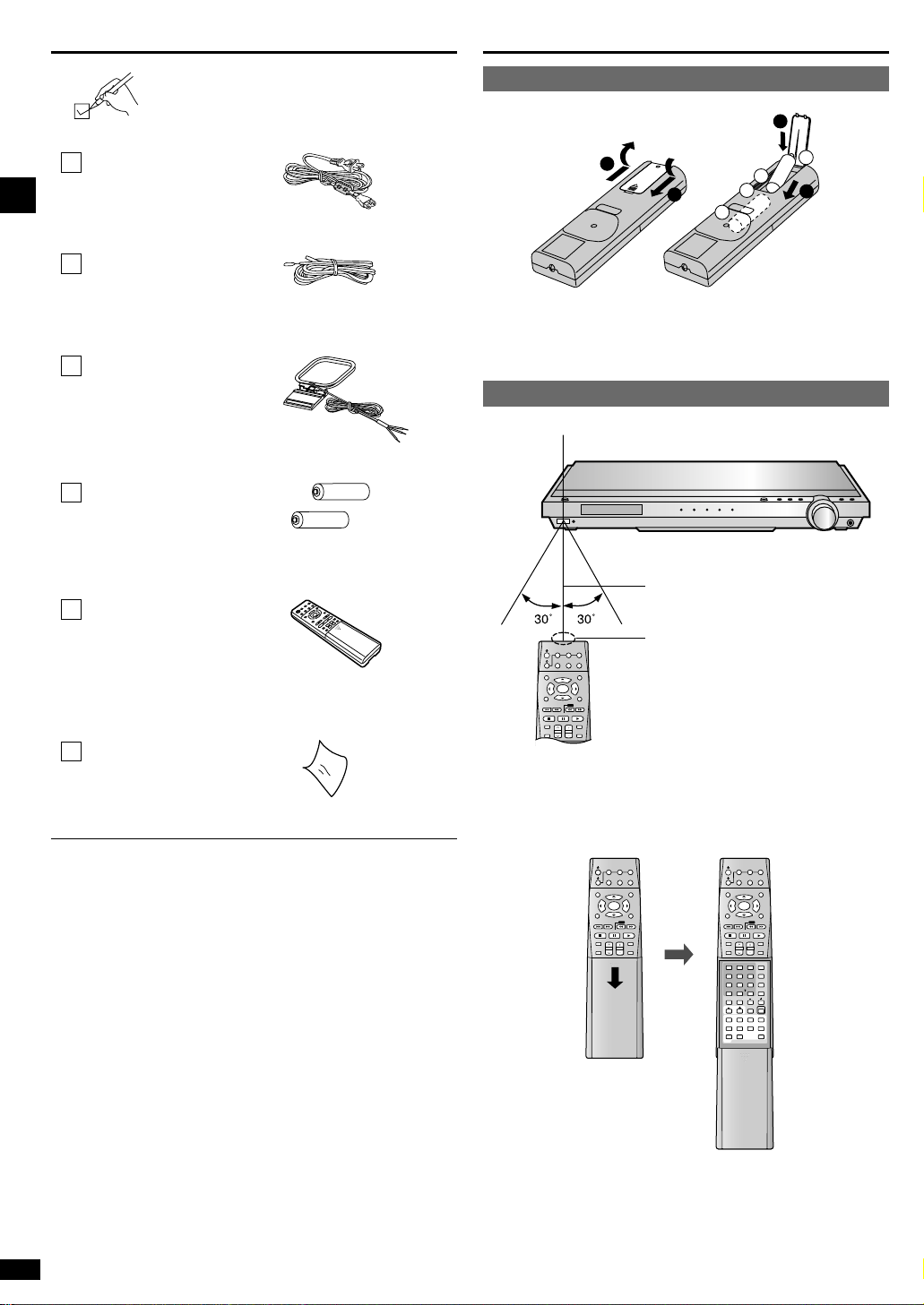
¡ Insert so the poles (+ and –) match those in the remote control.
¡ Do not use rechargeable type batteries.
¡ Keep the transmission window and the unit’s sensor free from dust.
¡ Operation can be affected by strong light sources, such as direct
sunlight, and the glass doors on cabinets.
How to open the remote control
Please check and identify the supplied
accessories.
1 AC power supply cord
(REZ1499)
Use the numbers indicated in parentheses when asking for replacement
parts.
(Only for U.S.A.)
To order accessories contact 1-800-332-5368 or web site
(http://www.panasonic.com).
2 Batteries
1 Remote control
(EUR7502XJ0)
1 AM loop antenna
(RSA0033C)
1 Cleaning cloth
(RFE0088-1)
1 FM indoor antenna
(RSA0006-J)
DVD
TOP MENU
MENU
TV
VCR
RETURN
PAUSESTOP
SOUND MODE
CHANNEL VOLUME
PLAY
/SEARCH
SKIP
DISPLAY
MUTING
SUBWOOFER SUBWOOFER
SFC SFC
ENTER
DVD
TOP MENU
MENU
TV
VCR
RETURN
PAUSESTOP
SOUND MODE
CHANNEL VOLUME
PLAY
/SEARCH
SKIP
DISPLAY
MUTING
ENTER
TEST
36251
4
987
0
DIRECT TUNING/
DISC
10/ENTER
TONE
DELAY
LEVEL
TIMERTV/VIDEO
REPEAT
DVD
L BALANCE R
A-B
REPEAT
MARKER
TV VOL
SUB TITLE
SETUP AUDIO ANGLE
POSITION
MEMORY
GROUP
PAGE
DVD 6CH
DIGITAL
TUNER/
BAND
INPUT
SELECTOR
RECEIVER
RECEIVER
DIGITAL
TUNER/
BAND
INPUT
SELECTOR
RECEIVER
RECEIVER
SLOW SLOW
Supplied accessories
The remote control
Remote control signal sensor
Transmission window
7 meters (23 feet)
SUBWOOFER
SFC
DVD
TOP MENU
MENU
DIGITAL
TV
VCR
RETURN
PAUSESTOP
SOUND MODE
CHANNEL VOLUME
PLAY
/SEARCH
SKIP
DISPLAY
MUTING
ENTER
TUNER/
BAND
INPUT
SELECTOR
RECEIVER
RECEIVER
SLOW
Batteries
Use
Before use
INPUT
75Ω
TV DVD
LOOP
EXT
MONITOR OUT
IN
IN
INOUT OUT
VCR
VIDEO
SUBWOOFER
VCR
OUT
IN
AUDIO
RL
RL
RL
RL
FRONT
CENTER
SURROUND
SPEAKERS (6~8Ω) HAUT-PARLEURS
LOOP
GND
ANT
AM
ANT
FM
ANT
GND
L
R
AC IN
5
RQT6501
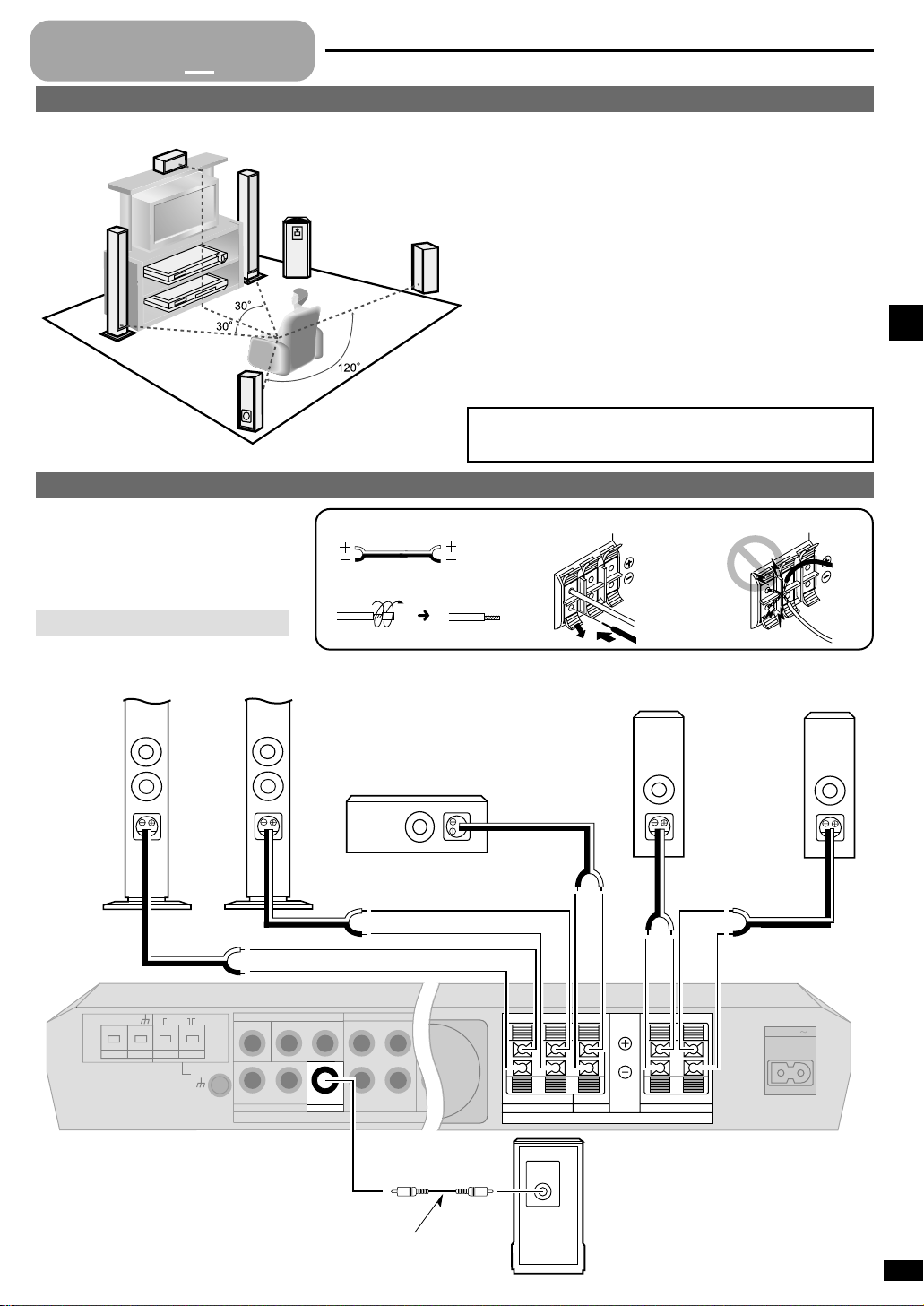
Front speakers (A left B right)
Place on the left and right of the TV at seated ear height so that there is
good coherency between the picture and sound.
Center speaker (C)
Place underneath or above the center of the TV. Aim the speaker at the
seating area.
Surround speakers (D left E right)
Place slightly behind the seating area, about one meter (3 feet) higher
than ear level.
Subwoofer (F)
The subwoofer can be placed in any position as long as it is at a
reasonable distance from the TV.
Note that some experimentation can yield the smoothest low frequency
performance. Placement near a corner can increase the apparent output
level, but can result in unnatural bass.
The front, center, and surround speakers should be placed at
approximately the same distance from the seating area. The angles
in the diagram are approximate.
A
B
C
D
E
F
Cable Speaker terminals Do not short circuit.
Twist the wire.
Speaker connections
Step
1
2 3 4
Peripheral equipment and cables sold separately unless otherwise indicated.
Placement of speakers
Connecting speakers
Other connections are possible depending on
your speaker system.
See your speaker system’s operating
instructions for details.
Turn off the receiver before connecting
the speakers.
Speaker Impedance: 6–8 Ω
Monaural connection cable
F
Active subwoofer
C
AB
Front speaker
(right)
Front speaker
(left)
Surround speaker
(right)
Surround speaker
(left)
ED
Center speaker
Step 1
TV DVD TV DVD/DVD 6CH
L
R
MONITOR OUT
IN
IN
INOUT OUT
VCR
VIDEO
SUBWOOFER
VCR
OUT
IN
AUDIO
IN
FRONT
CENTER
SURROUND
SUBWOOFER
(DVD) (TV)
OPT 2
IN
COAXIAL
OPT 1
DIGITAL
L
R
L
R
L
R
LOOP
EXT
LOOP
GND
ANT
AM
ANT
6
RQT6501
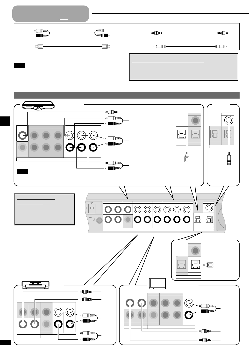
Stereo connection cable
White (L)
Red (R)
Video connection cable
Optical fiber cable Coaxial cable
To connect equipment, refer to the appropriate operating
instructions.
¡Do not bend the optical fiber cable.
¡Turn off all components before making any connections.
¡Use digital connection to enjoy Dolby Digital or DTS (\page 11).
¡Use analog connection to enjoy sources that cannot be decoded on
this unit and to record a source (\pages 11 and 20).
Note
VIDEO
IN
VIDEO
OUT
AUDIO
OUT
AUDIO
IN
TV DVD
MONITOR OUT
IN
IN
INOUT OUT
VCR
VIDEO
SUBWOOFER
VCR
OUT
IN
L
R
VCR TV or monitor
TV
AUDIO
IN
TV DVD
MONITOR OUT
IN
IN
INOUT OUT
VCR
VIDEO
SUBWOOFER
VCR
OUT
IN
L
R
L
R
AUDIO
OUT
VIDEO
OUT
VIDEO
IN
(DVD) (TV)
OPT 2
IN
COAXIAL
OPT 1
DIGITAL
DIGITAL
OUT
Equipment connections
Step
1
2
3 4
Changing the digital input settings
You can change the input settings for the digital terminals if
necessary. Note the equipment you have connected to the
terminals, then change the settings (\page 21).
Using DVD analog
connections
To enjoy multichannel linear PCM
when using DVD-AUDIO you need
to make connections via the analog
6CH terminals.
TV, VCR, and DVD player
DIGITAL AUDIO OUT
AUDIO OUT
(CENTER, SUBWOOFER)
VIDEO OUT
AUDIO OUT
(FRONT L, R)
AUDIO OUT
(SURROUND L, R)
DVD
IN
OUT
SUBWOOFER
AUDIO
TV
VCR
OUT
IN IN
L
R
FRONT
CENTER
SURROUND
SUBWOOFER
L
R
L
R
L
R
DVD/DVD 6CH
Connect to FRONT L, R if your DVD player does not have 6 channel output.
Note
DVD player Coaxial
(DVD) (TV)
OPT 2
IN
COAXIAL
OPT 1
DIGITAL
DIGITAL OUT
Step 2
Satellite receiver etc.
COAXIAL
(DVD) (TV)
OPT 2
OPT 1
DIGITAL
IN
7
RQT6501
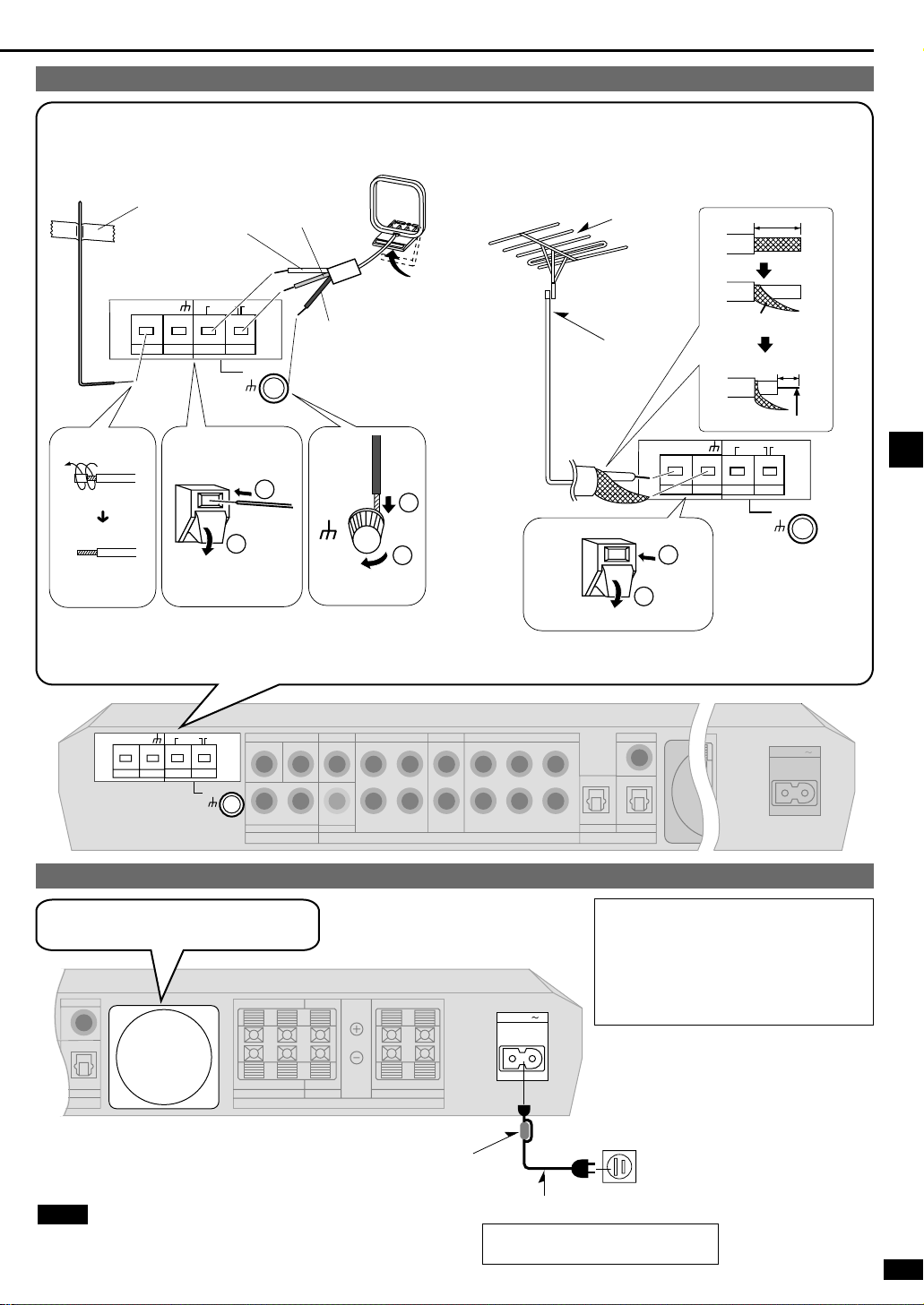
CAUTION:
TO PREVENT ELECTRIC
SHOCK MATCH WIDE BLADE
OF PLUG TO WIDE SLOT,
FULLY INSERT.
The included AC power supply cord is for use with this unit only. Do not
use it with other equipment.
Note
Household AC outlet
(AC 120 V/60 Hz)
Connect this cord after all other cables
and cords are connected.
AC power supply cord (included)
Connecting the AC power supply cord and other information
(TV)
RL
RL
RL
RL
OPT 2
IN
FRONT
CENTER
SURROUND
SPEAKERS (6~8Ω) HAUT-PARLEURS
COAXIAL
AC IN
The cooling fan operates at high power output
levels only.
TV DVD TV DVD/DVD 6CH
MONITOR OUT
IN
IN
INOUT OUT
VCR
VIDEO
SUBWOOFER
VCR
OUT
IN
AUDIO
IN
(DVD ) (TV)
OPT 2
IN
COAXIAL
OPT 1
DIGITAL
L
R
FRONT
CENTER
SURROUND
SUBWOOFER
L
R
L
R
L
R
LOOP
GND
ANT
AM
ANT
FM
ANT
GND
LOOP
EXT
AC IN
75Ω
20 mm (25/32")
Shield braid
10 mm (3/8")
Core wire
White
Red
Black
Keep the antenna cord away from DVD players and other cords.
Fix the other end of the antenna
where reception is best.
FM indoor antenna (included) AM loop antenna
(included)
Adhesive tape
FM outdoor antenna
¡ Disconnect the FM indoor antenna.
¡ The antenna should be installed by a competent technician.
¡ Twist the coaxial cable’s shield braid firmly and connect it to the
GND terminal.
FM outdoor antenna
75 Ω coaxial cable
Antennas
Peripheral equipment and cables sold separately unless otherwise indicated.
Step 2
Noise Filter
¡Do not remove the noise filter from the AC power supply cord.
ANT
GND
LOOP
75Ω
FM
1
EXT
LOOP
GND
ANT
2
AM
ANT
LOOP
GND
ANT
1
2
GND
LOOP
LOOP
GND
ANT
ANT
ANT
75Ω
FM
AM
EXT
2
1
8
RQT6501
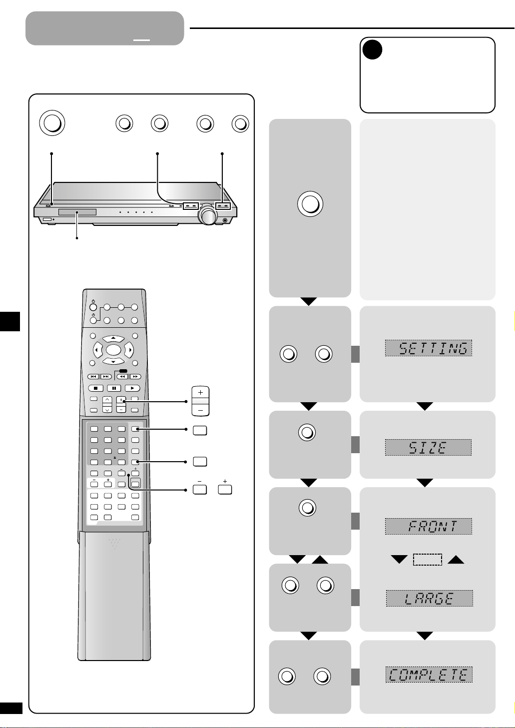
Change the settings to suit your speakers and units to the environment
in which you are using them. Before making any changes, read the
descriptions of the settings, note the factory settings and ranges, and
refer to the equipment’s instructions.
Enter the setting mode.
Set the size to suit your speakers
LARGE: For speakers that can
reproduce a full sound range,
particularly the bass range
below 100 Hz.
SMALL: For speakers that cannot
adequately reproduce the bass
range. This setting is sufficient
for most speakers if you are
using a subwoofer.
NONE: For speakers you haven’t
connected (center or surround).
The factory settings are:
FRONT: LARGE
CENTER and SURROUND:SMALL
For the subwoofer (SUB-WFR), select
YES if you have connected one (factory
setting), or NO if you have not.
1
Press at the
same time.
Select “SIZE”.
Select the speaker.
Change the setting.
Exit the setting mode.Press at the
same time.
Repeat
SIZE
Settings
Step
1 2
3
4
Step 3
Repeat these steps for each speaker
channel.
POWER
8
Display
MEMORY TUNE MODE
RECEIVER
DVD
TV
TUNER/
DIGITAL
BAND
SELECTOR
RECEIVER
TOP MENU
ENTER
DISPLAY
/SEARCH
SLOW
SKIP
PAUSESTOP
PLAY
CHANNEL VOLUME
SOUND MODE
SFC
4
DIRECT TUNING/
DISC
L BALANCE R
TV VOL
SETUP AUDIO ANGLE
REPEAT
GROUP
DVD
0
SUB TITLE
A-B
REPEAT
PAGE
MUTING
SUBWOOFER
36251
987
10/ENTER
MARKER
VCR
INPUT
MENU
RETURN
TEST
TONE
DELAY
LEVEL
TIMERTV/VIDEO
POSITION
MEMORY
DVD 6CH
2
VOLUME
TEST
LEVEL
TUNING
1
POWER
8
MEMORY TUNE MODE
MEMORY
TUNE MODE
2
TUNING
1
MEMORY TUNE MODE
 Loading...