

Panasonic SA-VK91DGCP, SB-WVK91, SB-VK91, SA-VK91D, SA-VK91DGC Service Manual
...
n AMPLIFIER SECTION
RMS Output Power : Dolby Digital Mode
Front - High Ch
90 W per channel (6 Ω), 1 kHz, 10% THD
Front - Low Ch
45 W per channel (12 Ω ), 100 Hz, 10% THD
Surround Ch
45 W per channel (6 Ω), 1 kHz, 10% THD
Center Ch
100 W per channel (6 Ω), 1 kHz, 10% THD
Subwoofer
95 W per channel (6 Ω), 100 Hz, 10% THD
Total RMS Dolby Digital mode power
650 W
PMPO output power 7300 W
n FM/AM TUNER, TERMINALS SECTION
Preset station FM 15 stations
AM/MW 15 stations
Frequency Modulation (FM)
Frequency range 87.50 - 108.00 MHz (50 kHz step)
Sensitivity 2.5µV (IHF)
S/N 26dB 2.2µV
A
ntenna terminals 75Ω (unbalanced)
A
mplitude Modulation (AM/MW)
Frequency range 522 - 1629 kHz (9 kHz step)
520 - 1630 kHz (10 kHz step)
A
M sensitivity S/N 20 dB at 1000 kHz
560µV/m
© 2004 Panasonic AVC Networks Singapore Pte.
Ltd. (RCB Registration Number: 197701580H) All
rights reserved. Unauthorized copying and
distribution is a violation of law.
SA-VK91DGCS
SA-VK91DGCP
Colour
(S)... Silver Type
A
udio performance (Amplifier)
Input sensitivity/I nput impedance
A
ux 250 mV, 20 kΩ
Phone jack
Terminal Stereo, 3.5 mm jack
Mic jack
Sensitivity 0.7 mV, 600 Ω
Terminal Mono, 6.3 mm jack (2 system)
n CASSETTE DECK SECTION
Type Auto Reverse
Track system 4 Track, 2 Channel
Head Record/Playback Solid Permalloy Head
Erasure Double Gap Ferrite Head
Motor DC Servo Motor
Recording System AC Bias 100 kHz
Erase System AC Erase 100 kHz
Tape Speed 4.8 cm/s
Overall Frequency Response (+3, -6 dB) at DECK OUT
Normal (TYPE I) 35 Hz - 14 kHz
S/N Ratio 50 dB (A weighted)
Wow and Flutter 0.18 % (WRMS)
Fast Forward and Rewind Time Approx. 120 seconds with
C-60 cassette tape
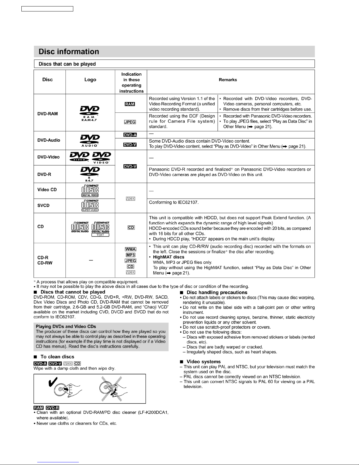
n DISC SECTION
Disc played [8 cm or 12 cm]
(1) DVD-RAM (DVD-VR compatible, JPEG formatted disc)
(2) DVD-Audio
DVD Stereo System
Specifications
ORDER NO. MD0407366C3
(3) DVD-Video
(4) DVD-R (DVD-Video compatible)
(5) CD-Audio (CD-DA)
(6) Video CD
(7) SVCD (Conforming to IEC62107)
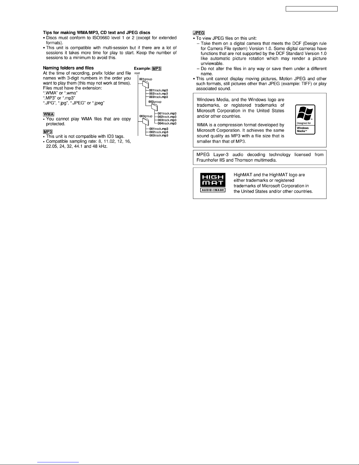
(8) CD-R/CD-RW (CD-DA, Video CD, SVCD, MP3, WMA, JPEG
formatted disc)
(9) MP3/WMA*
· Compatible compression rate:
MP3: between 32 kbps and 320 kbps
WMA: between 48 kbps and 192 kbps
(10) JPEG*
· Exif Ver 2.1 JPEG Baseline files
· Picture resolution: between 320x240 and 6144x4096 pixels
(Sub sampling is 4:2:2 or 4:2:0)
(11) HighMAT Level 2 (Audio and Image)
· The total combined maximum number of recognizable audio and
picture contents and groups: 4000 audio and picture contents
and 400 groups.
Pick up
Wavelength (DVD/CD) 662 nm/785 nm
A
udio ouptut (Disc)
Number of channels 5.1ch(FL,FR,C,SL,SR,SW)
A
udio performance (measurement at: Line out terminal)
Frequency response
CD-Audio 4Hz-20kHz(+1,-2dB)
n VIDEO SECTION
Video system
Signal system PAL625/50, PAL525/60, NTSC
Composite video output
Output level 1Vp-p(75Ω)
Terminal Pin jack (1 system)
S VIDEO output
Y output level 1Vp-p(75Ω)
C output level 0.3 Vp-p (75Ω)(PAL)
0.286 Vp-p (75Ω )(NTSC)
Terminal S terminal (1 system)
Component video output (480P/480I)
Y output level 1Vp-p(75Ω )
1 Before Use
4
2 Before Repair and Adjustment
4
3 Protection Circuitry
4
4 Safety Precautions
4
4.1. General Guidelines
4
PBoutput level 0.7 Vp-p (75 Ω)
PRoutput level 0.7 Vp-p (75 Ω )
Terminal
Pin jack (Y: green, PB:blue,PR:red)(1system)
n GENERAL
Power supply
AC 110V/127V/220-230V/240V, 50/60Hz
Power consumption 313 W
Power consumption in standby mode:
1W
Dimensions (WxHxD) 250 x 330 x 372 mm
Mass 9.6 kg
Operating temperature range +5°Cto+35°C
Operating humidity range 5% to 90% RH (no condensation)
n SYSTEM
SC-VK91D (GCS) Music Center: SF-VK91D (GCS)
Front Speakers: SB-VK91D (GC)
Center Speaker: SB-PC81A (GC)
x1
Surround Speakers: SB-PS81A
(GC) x 2
Subwoofers: SB-W VK91 (GC) x 2
SC-VK91D (GCP) Music Center: SF-VK91D (GCP)
Front Speakers: SB-VK91D (GC)
Center Speaker: SB-PC81A (GC)
x1
Surround Speakers: SB-PS81A
(GC) x 2
Subwoofers: SB-W VK91 (GC) x 2
SF-VK91D GCS-S consists of SA-VK91D GCS-S & SB-PT81A GC-S
SF-VK91D GCP-S consists of SA-VK91D GCP-S & SB-PT81A GC-S
SB-PT81A GC-S consists of SB-PS81 GC (x 2) & SB-PC81A GC (x
1)
Notes:
1. Specifications are subject to change without notice. Mass and
dimensions are approximate.
2. Total harmonic distortion is measured by the digital spectrum
analyzer.
5 Prevention of Electro Static Discharge (ESD) to
Electrostatically Sensitive (ES) Devices
5
6 Handling the Lead-free Solder
6
6.1. About lead free solder (PbF)
6
7 Cautions to be taken when handling Optical Pickup
7
7.1. Handling Optical Pickup
7
CONTENTS
Page Page
2
SA-VK91DGCS / SA-VK91DGCP

7.2. Replacing Precautions for Optical Pickup Unit 7
7.3. Grounding for Preventing Electrostatic Destruction
7
8 Precaution of Laser Diode
8
9 Accessories
9
10 Operation Procedures
10
11 Disc information
12
12 About HighMAT
14
12.1. What is HighMAT?
14
12.2. Why use HighMAT?
14
12.3. The advantages of using HighMAT
14
12.4. Outline of the HighMAT standard
15
13 Procedure for repairing the set
17
13.1. Distinguish the problem
18
13.2. Diagnosis of Optical Pick-up Unit
21
14 Optical Pickup Self-Diagnosis and Replacement Procedure
23
14.1. Self-diagnosis
23
14.2. Cautions to Be Taken During Replacement of Optical
Pickup and Spindle Motor
24
15 Self-Diagnosis Function
25
15.1. Automatic Displayed Error Codes
25
15.2. Memorized Error Codes
25
15.3. Mode Table 1
25
15.4. DVD/CD Self-Diagnosis Error Code Description
26
15.5. Error Codes Stored During No Play
26
15.6. Mode Table 2
26
15.7. Tray Lock Function
29
15.8. Things to Do After Repair
29
16 Cautions To Be Taken During Servicing
30
16.1. Recovery after the dvd player is repaired
30
16.2. DVD Player Firmware Version Upgrade Process
30
16.3. Firmware Version Upgrade Process by Using Disc and
Recovery Process
30
16.4. Using Recovery Disc
30
16.5. Total Usage Time Display
31
16.6. After replacement of DVD Module
31
17 Disassembly and Assembly of Main Component
32
17.1. Disassembly flow chart
32
17.2. Disassembly of Top Cabinet
33
17.3. Disassembly for DVD changer unit
33
17.4. Disassembly for Panel P.C.B., MIC P.C.B. & Tact Switch
P.C.B.
34
17.5. Disassembly of Main P.C.B., Speaker P.C.B., Sub Power
P.C.B., Power P.C.B., Transformer P.C.B. & Voltage
Selector P.C.B.
35
17.6. Replacement for traverse deck
38
17.7. Replacement for optical pickup unit (DVD mechanism)
38
17.8. Procedure for removing CD loading mechanism
41
17.9. CR16 mechanism disassembly procedure
41
17.10. CR16 MECHANISM ASSEMBLY PROCEDURE
47
17.11. Disassembly for Traverse Unit
58
17.12. Disassembly of Deck Mechanism Unit
60
17.13. Replacement for the cassette lid ass 馳
64
17.14. Counter-measure for tape trouble
65
18 Service Position
66
18.1. Checking Procedure
66
18.2. Checking the Main P.C.B., Speaker P.C.B., Power P.C.B.,
Sub Power P.C.B., Transformer P.C.B., Voltage Selector
P.C.B. and AC Inlet P.C.B.
66
18.3. Checking the Panel P.C.B., Tact P.C.B., Mic P.C.B., Deck
P.C.B. & Deck Mechanism P.C.B.
67
19 Measurements and Adjustments
68
19.1. Cassette Deck Section
68
19.2. Tuner Section
69
19.3. Alignment Points
70
20 Block Diagram
71
21 Schematic Diagram
80
21.1. Optical Pickup Unit Circuit
81
21.2. (A) DVD Module Circuit
82
21.3. (B) Main Circuit
89
21.4. (C) Panel Circuit , (D) Mic Circuit & (E) Tact Switch Circuit
98
21.5. (F) Deck Circuit & (G) Deck Mechanism Circuit
102
21.6. (H) Power Circuit
104
21.7. (I) Sub Power Circuit
106
21.8. (J) Speaker Circuit
107
21.9. (K) Transformer Circuit, (L) AC Inlet Circuit, (M) Voltage
Selector Circuit & (N) CD Loading Circuit
109
22 Printed Circuit Board
110
22.1. (A) DVD Module P.C.B. (Side: A & B )
110
22.2. (B) Main P.C.B.
112
22.3. (C) Panel P.C.B.
113
22.4. (D) Mic P.C.B. & (E) Tact P.C.B.
115
22.5. (F) Deck P.C.B. & (G) Deck Mechanism P.C.B.
116
22.6. (H) Power P.C.B.
117
22.7. (I) Sub Power P.C.B. & (N) CD Loading P.C.B.
118
22.8. (J) Speaker P.C.B.
119
22.9. (K) Transformer P.C.B.
121
22.10. (L) AC Inlet P.C.B. & (M) Voltage Selector P.C.B.
122
23 Wiring Connection Diagram
123
24 Illustration of ICs, Transistors and Diodes
125
25 Terminal Function of IC
126
25.1. IC6800 (C2CBJG000460) System Microprocessor
126
26 Parts Location and Replacement Parts List
128
26.1. Deck Mechanism (RAA3412-S)
129
26.2. DVD Loading Mechanism
132
26.3. Cabinet
136
26.4. Electrical Parts List
139
26.5. Packing Materials & Accessories Parts List
153
26.6. Packaging
154
3
SA-VK91DGCS / SA-VK91DGCP
1 Before Use
Be sure to disconnect the mains cord before adjusting the voltage selector.
Use a minus(-) screwdriver to set the voltage selector (on the rear panel) to the voltage setting for the area in which the unit will
be used. (If the power supply in your area is 117V or 120V, set to the “127V” position.)
Note that this unit will be seriously damaged if this setting is not made correctly. (There is no voltage selector for some countries,
the correct voltage is already set.)
2 Before Repair and Adjustment
Disconnect AC power, discharge Power Supply Capacitors C5815~C5818, C5829~C5830, C5835~C5836 and C5841 through a
10Ω, 5W resistor to ground.
DO NOT SHORT-CIRCUIT DIRECTLY (with a screwdriver blade, for instance), as this may destroy solid state devices.
After repairs are completed, restore power gradually using a variac, to avoid overcurrent.
Current consum ption at AC 110/127/220~230V, 50/60 Hz in NO SIGNAL at (vol. min, in CD mode) should be as below:
AC 50/60Hz 110 V ~1200mA
127 V ~1100mA
220-230 V ~ 700 mA
240 V ~ 650 mA
3 Protection Circuitry
The protection circuitry may have operated if either of the following conditions are noticed:
·
No sound is heard when the power is turned on.
·
Sound stops during a performance.
The function of this circuitry is to prevent circuitry damage if, for example, the positive and negative speake r connection wires are
“shorted”, or if speaker systems with an impedance less than the indicated rated impedance of the amplifier are used.
If this occurs, follow the procedure outlines below:
1. Turn off the power.
2. Determine the cause of the problem and correct it.
3. Turn on the power once again after one minute.
Note :
When the protection circuitry functions, the unit will not operate unless the power is first turned off and then on again.
4 Safety Precautions
4.1. General Guidelines
1. When servicing, observe the original lead dress. If a short circuit is found, replace all parts which have been overheated or
damaged by the short circuit.
2. After servicing, see to it that all the protective devices such as insulation barriers, insulation papers shields are properly
installed.
3. After servicing, make the following leakage current checks to prevent the customer from being exposed to shock hazards.
4.1.1. Leakage Current Cold Check
1. Unplug the AC cord and connect a jumper between the two prongs on the plug.
2. Measure the resistance value, with an ohmmeter, between the jumpered AC plug and each exposed metallic cabinet part on
the equipment such as screwheads, connectors, control shafts, etc. When the exposed metallic part has a return path to the
chassis, the reading should be between 1MΩ and 5.2MΩ.
When the exposed metal does not have a return path to the chassis, the reading must be ・.
4
SA-VK91DGCS / SA-VK91DGCP

Figure 1
4.1.2. Leakage Current Hot Check
(See Figure 1)
1. Plug the AC cord directly into the AC outlet. Do not use an isolation transformer for this check.
2. Connect a 1.5kΩ, 10 watts resistor, in parallel with a 0.15µF capacitor, between each exposed metallic part on the set and a
good earth ground such as a water pipe, as shown in Figure 1.
3. Use an AC voltmeter, with 1000 ohms/volt or more sensitivity, to measure the potential across the resistor.
4. Check each exposed metallic part, and measure the voltage at each point.
5. Reverse the AC plug in the AC outlet and repeat each of the above measurements.
6. The potential at any point should not exceed 0.75 volts RMS. A leakage current tester (Simpson Model 229 or equivalent) may
be used to make the hot checks, leakage current must not exceed 1/2 milliamp. In case a measurement is out of the limits
specified, there is a possibility of a shock hazard, and the equipment should be repaired and rechecked before it is returned to
the customer.
5 Prevention of Electro Static Discharge (ESD) to
Electrostatically Sensitive (ES) Devices
Some semiconductor (solid state) devices can be damaged easily by electricity. Such components commonly are called
Electrostatically Sensitive (ES) Devices. Examples of typical ES devices are integrated circuits and some field-effect transistors and
semiconductor “chip” components. The following techniques should be used to help reduce the inciden ce of component damage
caused by electro static discharge (ESD).
1. Immediately before handling any semiconductor component or semiconductor-equiped assembly, drain off any ESD on your
body by touchin g a known earth ground. Alternatively, obtain and wear a commercially available discharging ESD wrist strap,
which should be removed for potential shock reasons prior to applying power to the unit under test.
2. After removing an electrical assembly equiped with ES devices, place the assembly on a conductive surface such as aluminium
foil, to prevent electrostatic charge build up or exposure of the assembly.
3. Use only a grounded-tip soldering iron to solder or unsold er ES devices.
4. Use only an anti-static solder remover device. Some solder removal devices not classified as “anti-static (ESD protected)” can
generate electrical charge to damage ES devices.
5. Do not use freon-propelled chemicals. These can generate electrical charges sufficient to damage ES devices.
6. Do not remove a replacement ES device from its protective package until immediately before you are ready to install it. (Most
replacement ES devices are packaged with leads electrically shorted together by conductive foam, aluminium foil or
comparable conductive material).
7. Immediately before removing the protective material from the leads of a replacement ES device, touch the protective material
to the chassis or circuit assembly into which the device will be installe d.
Caution
Be sure no power is applied to the chassis or circuit, and observe all other safety precautions.
8. Minimize body motions when handling unpackaged replacement ES devices. (Otherwise harmless motion such as the brushing
together of your clothes fabric or the lifting of your foot from a carpeted floor can generate static electricity (ESD) sufficient to
damage an ES device).
5
SA-VK91DGCS / SA-VK91DGCP

6 Handling the Lead-free Solder
6.1. About lead free solder (PbF)
Distinction of PbF P.C.B.:
P.C.B.s (manufactured) using lead free solder will have a PbF stamp on the P.C.B.
Caution:
· Pb free solder has a higher melting point than standard solder; Typically the melting point is 50 - 70°F (30 - 40°C) higher. Please
use a high temperature soldering iron. In case of soldering iron with temperature control, please set it to 700 ± 20°F (370 ±
10°C).
· Pb free solder will tend to splash when heated too high (about 1100°F/600°C).
· W hen soldering or unsoldering, please completely remove all of the solder on the pins or solder area, and be sure to heat the
soldering points with the Pb free solder until it melts enough.
6
SA-VK91DGCS / SA-VK91DGCP
7 Cautions to be taken when handling Optical Pickup
The laser diode used inside optical pickup could be destroyed due to static electricity as a potential difference is caused by
electrostatic load discharged from clothes or human body. Handling the parts carefully to avoid electrostatic destruction during
repair.
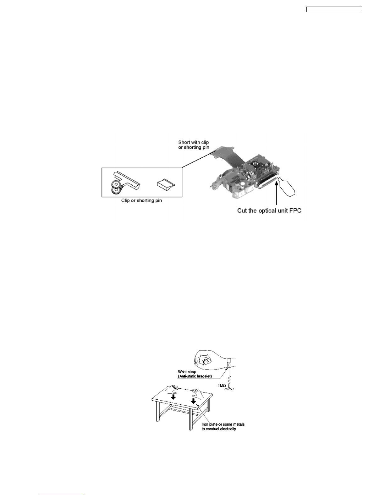
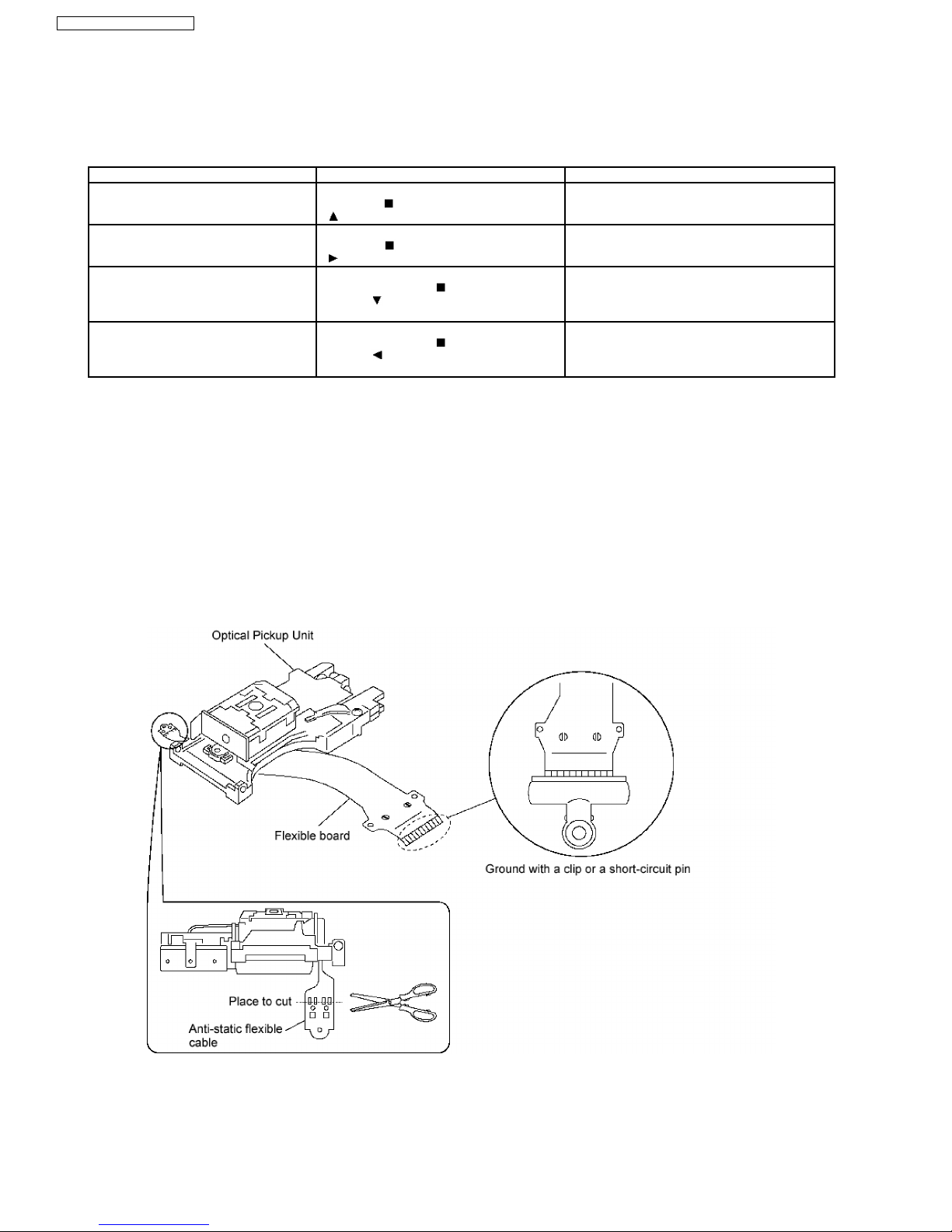
7.1. Handling Optical Pickup
1. Do not impact on optical pickup as the unit structurally uses an extremely precise technology.
2. Short-circuit the flexible cable of optical pickup remove from the circuit board using a short-circuit pin or clip in order to prevent
laser diode from electrostatic destruction (Refer to Fig. 7.1 and Fig. 7.2)
3. Do not handle flexible cables forcibly as this may cause snapping. Handle the parts carefully (Refer to Fig. 7.1)
4. A new optical pickup is equipped with an anti-static flexible cable. After replacing and connecting to the flexible board, cut the
anti-static flexible cable. (Refer to Fig. 7.1)
Fig. 7.1
7.2. Replacing Precautions for Optical Pickup Unit
DVD/CD Optical Pickup
The optical pickup by which part supply was carried out attaches the short clip to the flexible board for laser diode electrostatic
discharge damage prevention. Please remove the short clip and be sure to check that the short land is open, before connecting.
(Please remove solder, when the short land short-circuits.)
7.3. Grounding for Preventing Electrostatic Destruction
1. Human body grounding
Use the anti-static wrist strap to discharge the static electricity accumulated in your body. (Refer to Fig. 7.2)
2. Work place grounding
Place a conductive material (conductive sheet) or ironboard where optical pickup is placed. (Refer to Fig. 7.2)
Note :
Keep your clothes away from optical pickup as wrist strap does not release the static electricity charged in clothes.
Fig. 7.2
7
SA-VK91DGCS / SA-VK91DGCP
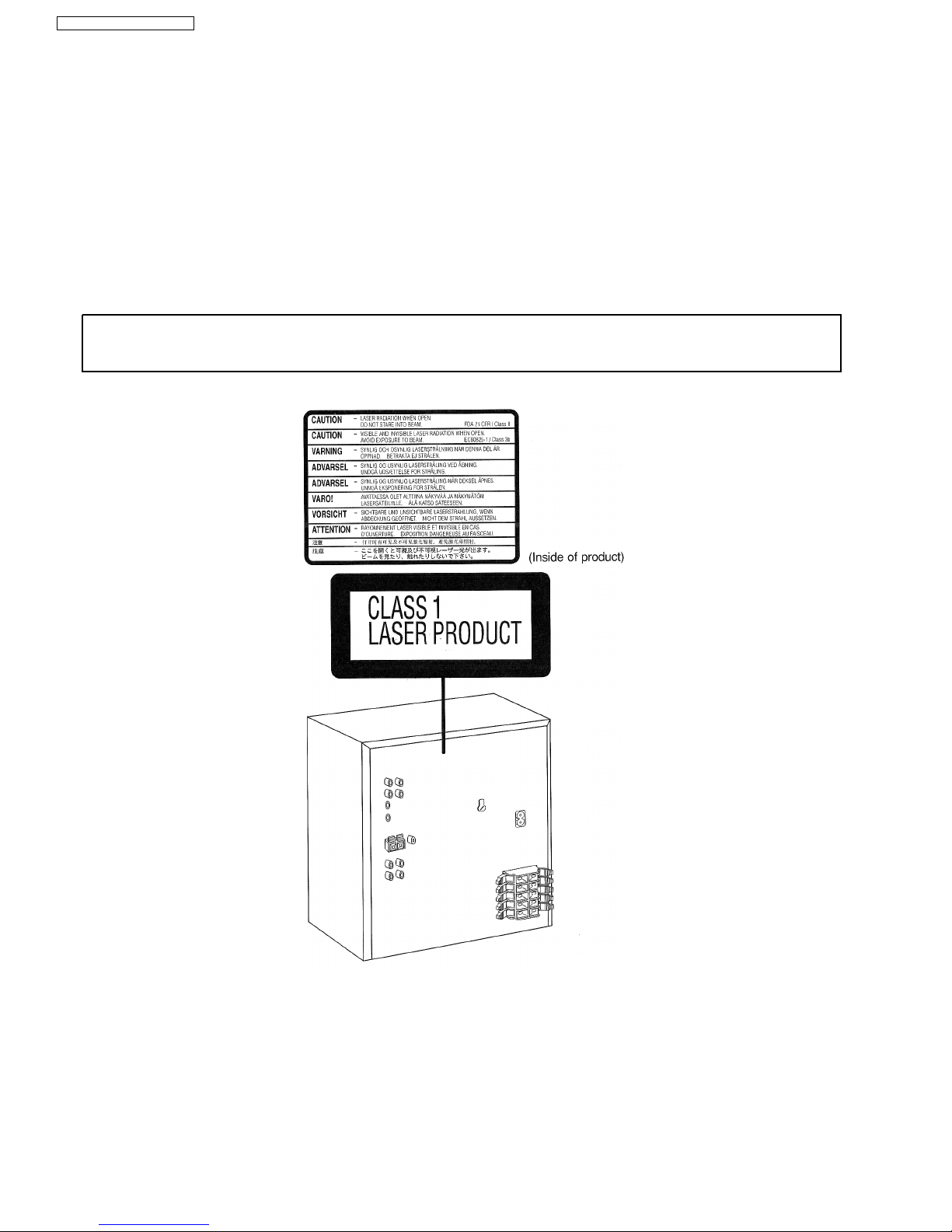
8 Precaution of Laser Diode
Caution :
This product utilizes a laser diode with the unit turned "ON", invisible laser radiation is emitted from the pick up lens.
Wavelength : 662 nm(DVD)/785 nm(CD)
Maximum output radiation power from pick up : 100 µW/VDE
Laser radiation from pick up unit is safety level, but be sure the followings:
1. Do not disassemble the optical pick up unit, since radiation from exposed laser diode is dangerous.
2. Do not adjust the variable resistor on the pick up unit. It was already adjusted.
3. Do not look at the focus lens using optical instruments.
4. Recommend not to look at pick up lens for a long time.
CAUTION!
THIS PRODUCT UTILIZES A LASER.
USE OF CONTROLS OR ADJUSTMENTS OR PERFORMANCE OF PROCEDURES OTHER THAN THOSE SPECIFIED HEREIN MAY RESULT
IN HAZARDOUS RADIATION EXPOSURE.
n Use of Caution Labels
8
SA-VK91DGCS / SA-VK91DGCP
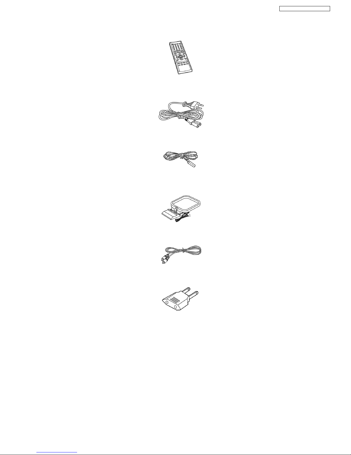
9 Accessories
Remote
control
AC power supply cord
FM indoor
antenna
AM indoor antenna
Video cable
AC Plug Adaptor
(For GCP only)
9
SA-VK91DGCS / SA-VK91DGCP
10 Operation Procedures
10
SA-VK91DGCS / SA-VK91DGCP
11
SA-VK91DGCS / SA-VK91DGCP
11 Disc information
12
SA-VK91DGCS / SA-VK91DGCP
13
SA-VK91DGCS / SA-VK91DGCP
12 About HighMAT
12.1. What is HighMAT?
This word combines the abbreviations of Matsushita Electric Industrial Co. Ltd. and High Performance Media Access Techn ology,
and is a trademark of Microsoft Corporation. The products with the HighMAT logo shown below are made according to the
HighMAT standard.
HighMAT is a format that allows users to save digital contents such as photographs, audio, and images on a CD. This gives
consistency in the way of reading data when general consumer products (such as DVD players) and PCs are used, and thus, it is
easy to operate for the user.
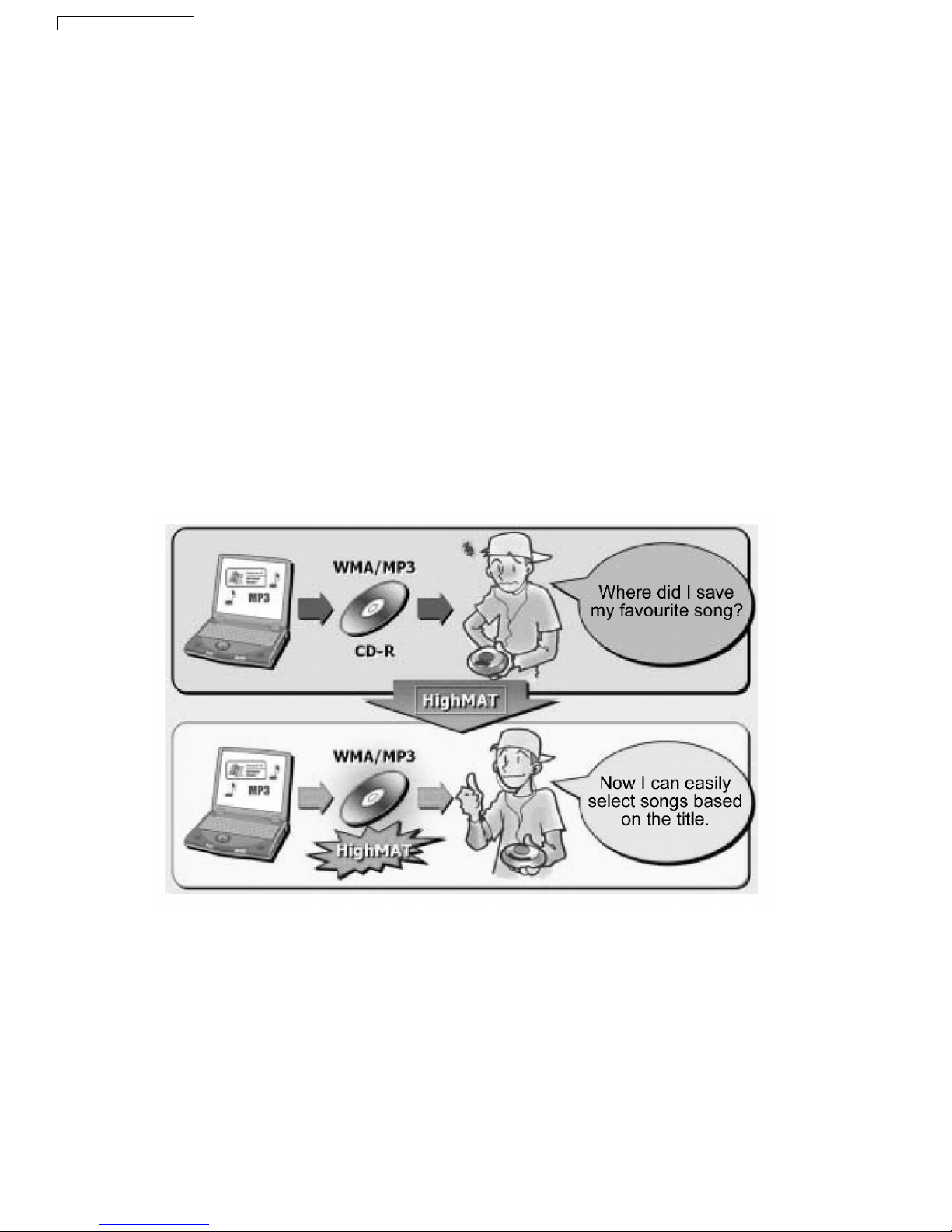
12.2. Why use HighMAT?
Up to now, there was no harmonized standard from playing digital content stored in CD-ROM formats (including CD-R) on
consumer products like DVD players.Therefore, we used to have problems such as follow:
· There was no common play list or attached information on contents, which is called metadata.
· The data compression method differed according to the equipment.
· As the number of CD-ROMs recorded increased retrieved the contents became more difficult.
· Because display and operation methods were different depending on the equipment, the play order of the content on the same
disc could change.
12.3. The advantages of using HighMAT
Applying the HighMAT standard will solve the following problems and will improve usabili ty.
· It will create a common user interface for both PC and consumer products.
· Regardless of the types of consumer products, such as DVD players, portable CD players, car stereos, and micro computers,
a consistent way to pay for digital content will be created and it will make it easier to retrieve data.
14
SA-VK91DGCS / SA-VK91DGCP
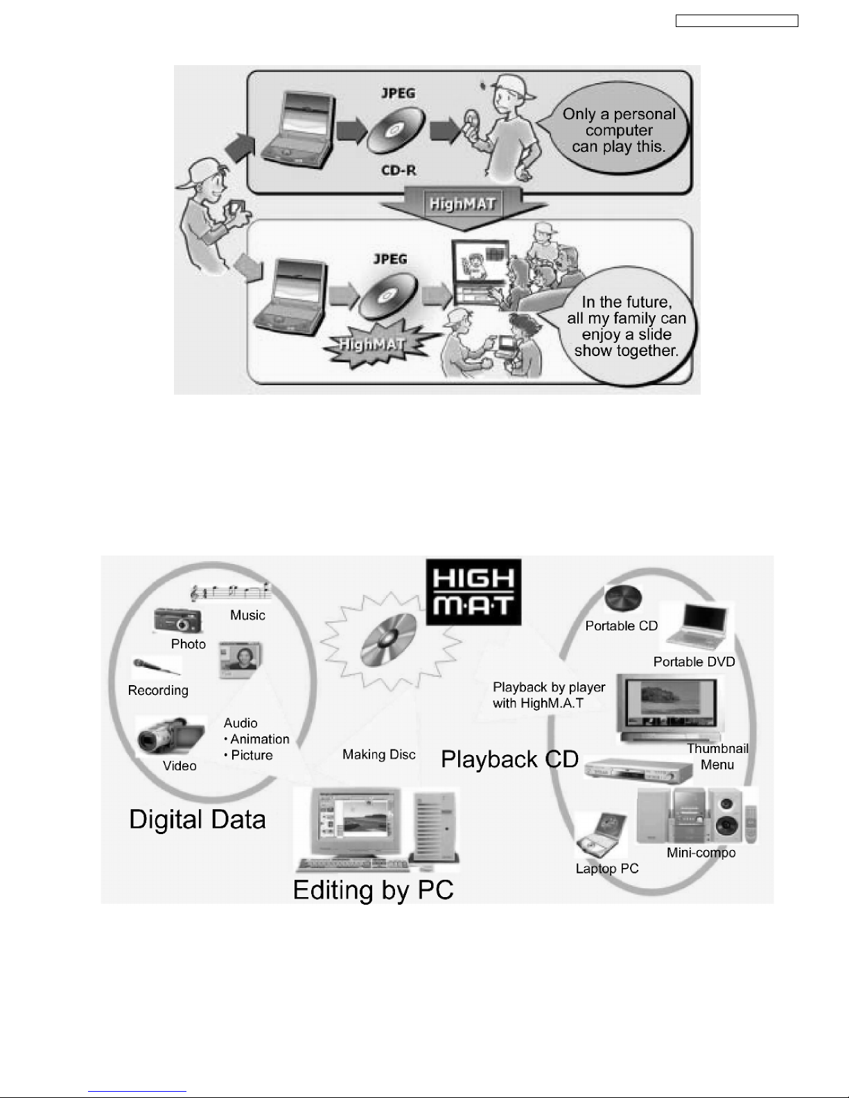
· You can also play digital content on the disc, which was created in accordance with the HighMAT format with a conventional
CD-ROM player.
12.4. Outline of the HighMAT standard
1. Recording medium
· CD-R/CD-RW
· Supports ISO 9660 Level Expan ded Joliet
· For multiple session
2. Support data format
· Level 1 player: WMA, MP3 (MPEG-1 Audio Layer 3)
· Level 2 player: WMA, MP3 (MPEG-1 Audio Layer 3), JPEG
· Level 3 player: WMA, MP3 (MPEG-1 Audio Layer 3), JPEG, WMV, MPEG4 (optional)
3. Limitation of data format
15
SA-VK91DGCS / SA-VK91DGCP

· W MA, MP3 (MPEG-1 Audio Layer 3) 64 kbps - 160.999 kbps, 44.1 KHz, stereo, fixed bit rate/ variable bit rate.
· W MA, V2 and above, excluding Lossless/Voice/Pro
· JPEG: Max 6M pixel, Maximum file size: 3 MB
4. Limitations regarding the number of files on the media, etc.
· Total numbe r of audio files: Maximum 450
· Total numbe r of still picture files: Maximum 999
· Total numbe r of animation files: Maximum 200
· Total numbe r of directories: Maximum 400
· Length of a file name: Maximum 108 characters (Unicode)
· Total numbe r of play lists: Maximum 200
· Number of contents in the playlist: Maximum 900
5. Composition of HighMAT disc
· Menu: Classified for the navigation of the HighMAT digital contents. When menu selected, its submenu or the play list will
be display ed.
· Play list: A list in which one or more digital contents are arranged in order
· Group: Sub-divided group of a play list.
· Digital Contents: Audio, still picture, and animation data.
16
SA-VK91DGCS / SA-VK91DGCP
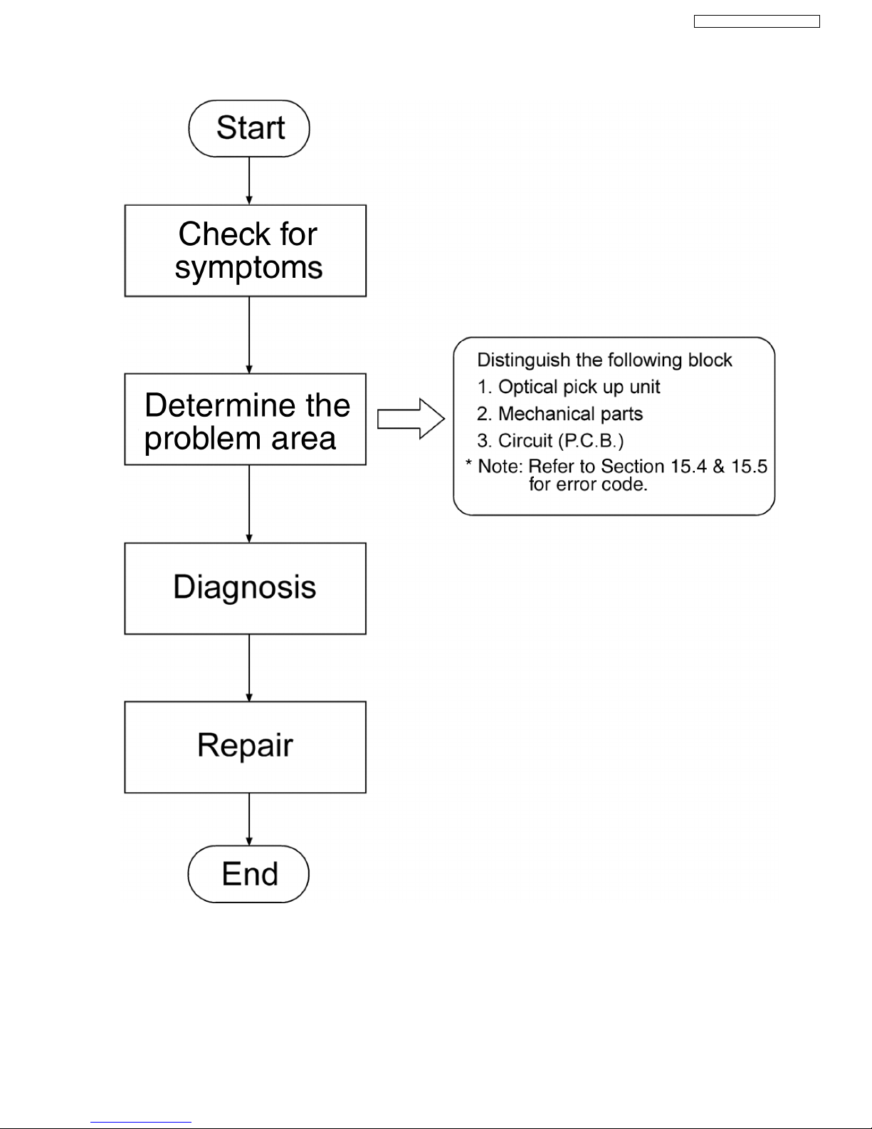
13 Procedure for repairing the set
17
SA-VK91DGCS / SA-VK91DGCP
13.1. Distinguish the problem
How to distinguish the trouble
1. View mechanical part if visual damage occurred.
Confirm the movement of mechanical parts assembly
(tray ass’y, loading mechanism ass’y, etc.).
2. Diagnose if Optical Pickup Unit is faulty (refer to
diagnosis of Optical Pickup Unit).
3. If mechanism and OPU are OK, it is P.C.B.
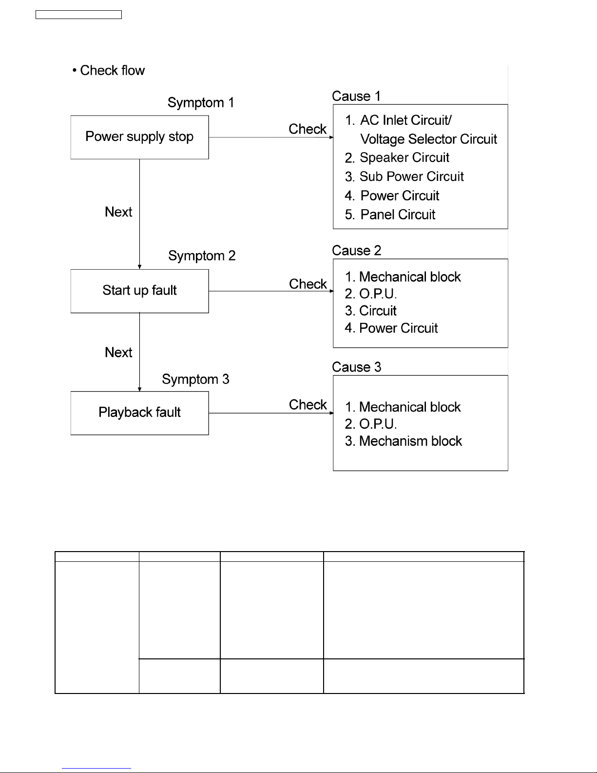
13.1.1. Troubleshooting Guide Part 1
Checking Points Possible Faults Possible Reasons Countermeasure
AC Inlet Circuit/Voltage
Selector Circuit
1. Failure to power-up
the main unit.
2. Power On switch
· Wrong selection of AC
power to main unit.
· Voltage selector is faulty.
· AC inlet JK500 is faulty.
· AC Line filter L500 is
faulty.
· Power On switch broken.
· Replace of fuse if found faulty.
· Replace of voltage selector if found faulty.
· Replace of AC Inlet if found faulty or damaged.
· Replace AC Line filter is found faulty or damaged.
· Replace Power On button switch if necessary.
· If conditions as mentioned above is in good condition.
Check for wire connection. (W1/W2/W3/W4/W6/W7). If
connection is good, please proceed to check for
Transformer Circuit.
3. Intermittent Power
supply to main unit.
· Check for connection. · If condition 1 to 4 as mentioned above is in good
condition. Check for wire connection.
(W1/W2/W3/W4/W6/W7). If connection is good, please
proceed to check for Transforme r Circuit
18
SA-VK91DGCS / SA-VK91DGCP
Checking Points Possible Faults Possible Reasons Countermeasure
Transformer Circuit 1. No power supply
voltage to the Power
Circuit from AC In.
· Transformer no output
voltage.
· Power Line filter relay
RL502.
· D950 open circuit.
· Replace of Transforme r T501 if found faulty.
· Replace of Power Relay if found faulty.
Speaker Circuit 1. No supply voltage to
Power Supply Circuit
from Transformer
Circuit. (+VccL/+VccH/VccL/-VccH)
· Fuse F3/F4 blown.
· Rectifier Circuit problem.
· Replace fuse F3/F4 if found faulty.
· Replace D5832/D5831/D5846/D5847 if any is found to
be faulty or damage.
1. No supply voltage to
Main & Power Supply
Circuit from
Transformer Circuit.
(+VccL/+VccH/-VccL/VccH)
· Rectifier Circuit problem.
· F5801/FP5802 open
circuit.
· Replace D5844 if found faulty.
· Replace FP5801/FP5802 of the same type as indicated
in the part-list if found faulty.
1. No supply voltage to
Panel Circuit.
· Q5815/D5835 faulty. (-VP
voltage not sufficient to
power FL display at - 30V)
· Q5816/D5839 faulty. (Sys
6V not sufficient to power
micro-processor IC at 6V.
· Replace Q5815/D5835 if found faulty.
· Replace Q5816/D5839 if found faulty.
Sub Power Circuit 1. No output FL/FR
output signal.
· No supply voltage to
IC5803. (+VccL/+VccH/VccL/-VccH/+Vd/-Vd).
· Replace IC5803 if found faulty.
Power Circuit 1. No +9V/-
9V/SW5V/8V/LED9V/M
010V Supply Voltage to
Main Circuit.
· IC5802 problem. (Check
pin 2,8,9,10,11 for
voltages)
· Replace IC5802 if found faulty.
2. No output SL/SR/C
signal (Check for input
signal before
troubleshooting for
IC5801.)
· IC5801 problem. (Check
pin 1,2,5 for output signal)
· Replace IC5801 if found faulty.
13.1.2. Troubleshooting Guide Part 2
Checking Points Possible Faults Possible Reasons Countermeasure
Deck Circuit 1. No PLAYBACK
(PB)/Rec signal.
· IC1001 problem. (Check
pin 23/24 for PB input, pin
5/20 for PB output).
· Q1013/Q1012 shorted to
ground with no muting
OFF.
· Q1020/Q1021 shorted to
ground with no muting
OFF.
· Replace IC1001 if necessary.
· Replace Q1013/Q10 12 if necessary.
· Replace Q1020/Q10 21 if necessary.
2. Bias frequency.
· L1002 /IC1004/
Q1004/Q1005 problem.
Check level of bias
frequency and oscillation.
· Replace these components if necessary when level is
below specification.
3. No supply voltage
(+B/M0+B)
· See section on Panel
Circuit.
Panel Circuit 1. FL No Display
· -Vp too low to power FL
display.
· FL Display Driver IC
problem. (IC6803)
· See section on Power Circuit.
· Replace IC6803 is faulty.
2. Error codes
· See section on error codes
(Micro-processor IC6800)
Main Circuit 1. Audio Signal (I/P &
O/P) problem.
· Check for IC2815. · Replace IC2815 if faulty.
2. Video Signal
problem.
· Refer to below section.
13.1.3. Checking of VIDEO COMPONENT OUTPUT
VIDEO
SIGNAL
Y C CR/PR/R CB/PB/B PY/Y/G
Input Pin 5 (IC2809) Pin 3 (IC2809) Pin 14 (IC2809) Pin 12 (IC2809) Pin 8 (IC2809)
VIDEO
SIGNAL
Y C CR CB/PB/B PY
Output Pin 24/25 (IC2809) Pin 32 (IC2809) Pin 17 (IC2809) Pin 19 (IC2809) Pin 21/22 (IC2809)
19
SA-VK91DGCS / SA-VK91DGCP

Terminal Defination (IC2809 - C9ZB000003 77)
Pin No Pin Name Pin Description
21/22 PYOUT1/PYOUT2 Signal Output Terminal for luminance signal (progressive type)
17/19 CrOUT/CbOUT Signal Output Terminal for color-difference signal
32 COUT Signal Output Terminal for chroma signal
29/30 MIXOUT1/MIXOUT2 Signal Ouptut Terminal for Y/C Mix Signal
24/25 YOUT1/YOUT2 Signal Output Terminal for luminance signal (interlaced type)
3/12/14 CIN/CBIN/CRIN Input signal terminal for chroma signal and color difference
5/8 YIN/PYIN Input signal terminal for luminance signal
20
SA-VK91DGCS / SA-VK91DGCP
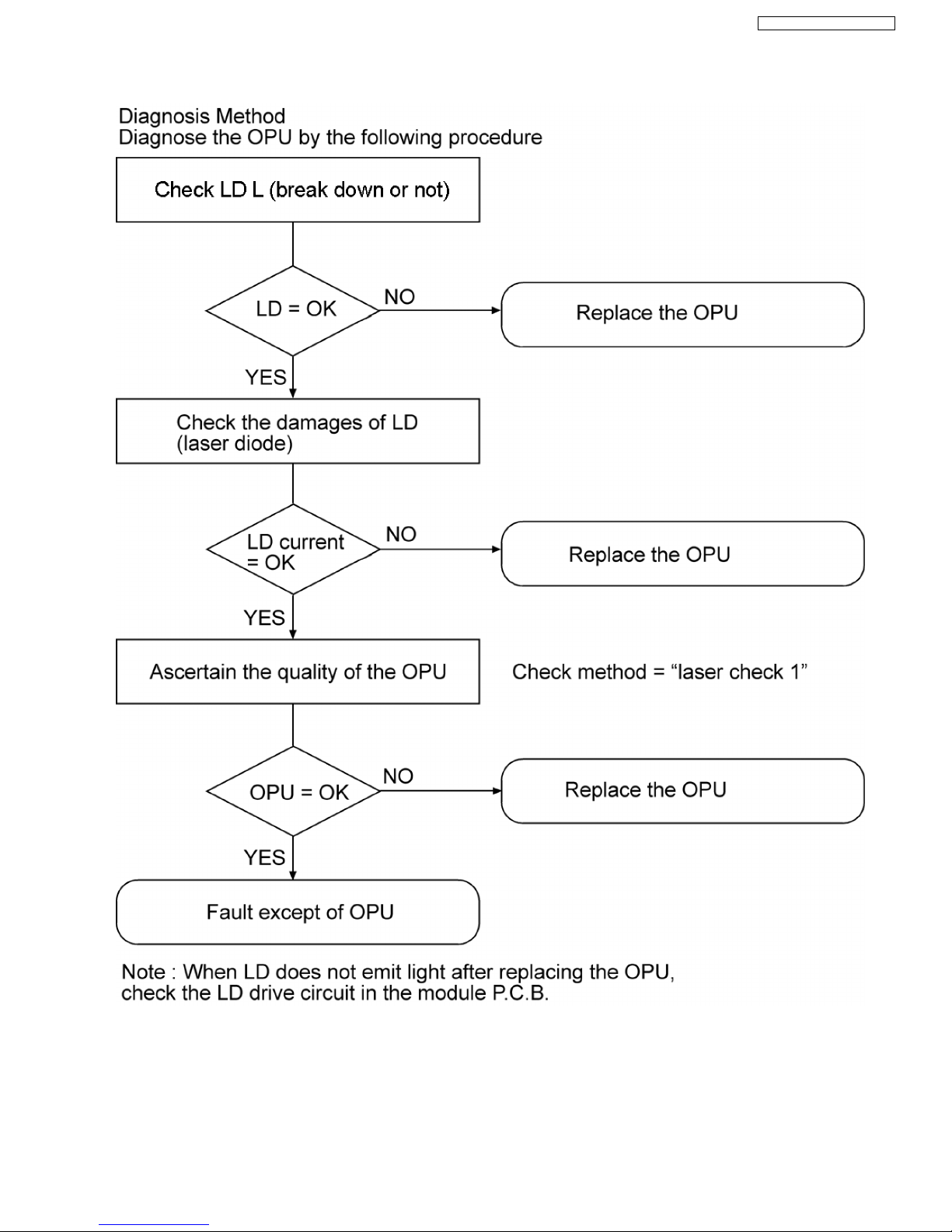
13.2. Diagnosis of Optical Pick-up Unit
How to distinguish Laser destruction/damage
Confirmation 1
Remove cover of mechanism block so that you will see the lens of optical pickup.
Confirm emission of laser at the moment when power switch is turned on.
If there is no laser emission, laser diode is faulty.
Confirmation 2
21
SA-VK91DGCS / SA-VK91DGCP

While press and hold “STOP” on main unit , press “Display” button on the remote controller. Unit display laser current on FL.
From the reading of display, you can judge if laser diode is damaged or not.
Reading on the right side should be less than 70. If reading is more than 70, laser is damaged.
How to confirm if Optical Pickup is OK
Confirmation 1
1. Confirmation of jitter value with test disc. (Refer below for how to check jitter)
2. Lens cleaning.
3. Reconfirm jitter value.
4. Perform tile adjustment. (Refer to tilt adjustment)
5. Reconfirm jitter value. (To confirm jitter value, while pressing “STOP” on main unit and “5” on remote controller.)
Unit display jitter value on FL.
Confirmation 2
If servo is very unstable due to optical error and you cannot confirm jitter value, clean the lens and check appearance of pick
up unit (cutting coil of actuator, etc), then check circuitry.
22
SA-VK91DGCS / SA-VK91DGCP
14 Optical Pickup Self-Diagnosis and Replacement
Procedure
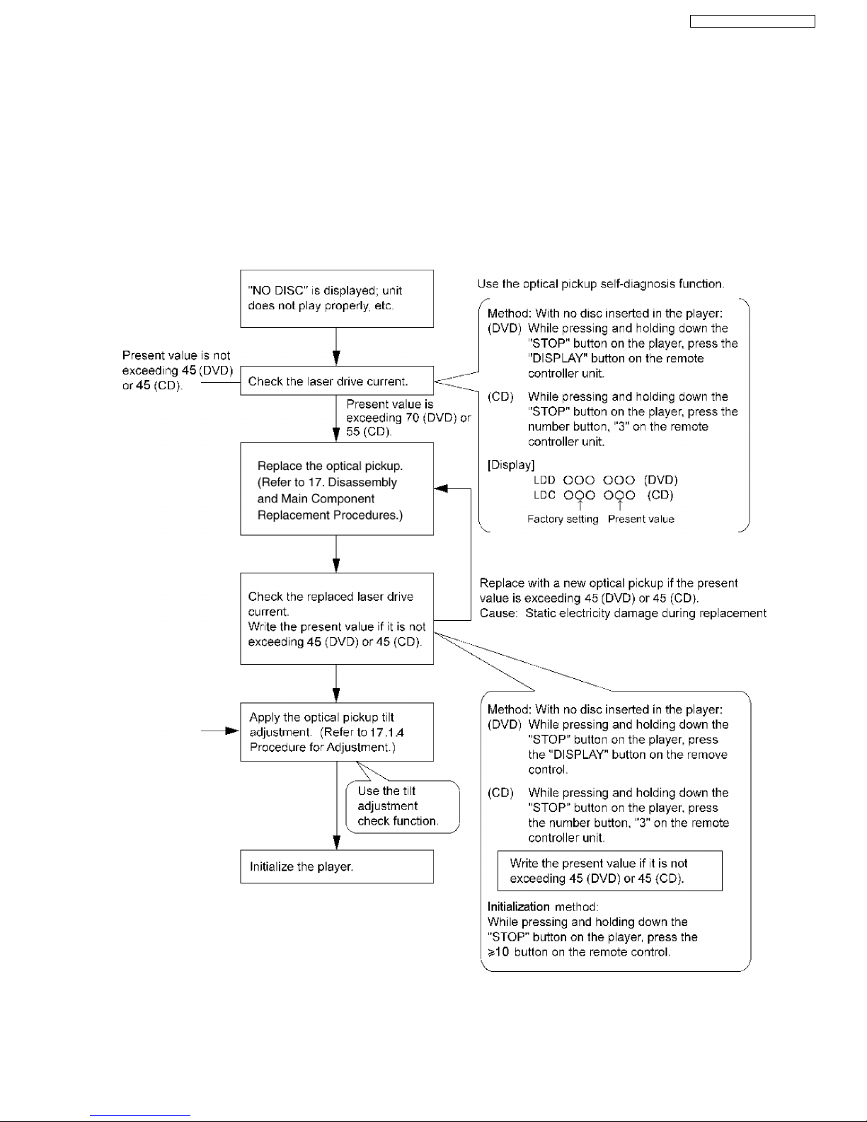
14.1. Self-diagnosis
This unit is equipped with the optical pickup self-diagnosis function and the tilt adjustment check function. Follow the procedure
described below during repair in order to perform self-diagnosis and tilt adjustment effectively. Especially when “NO DISC” is
displayed, be sure to apply the self-diagnosis function before replacing with an optical pickup. Replac ement of optical pickup
generally requires when the present value of laser drive exceeds 45 (DVD) or 45 (CD).
Note:
Start diagnosis within three minutes after turning on the power (as diagnosis fails when the unit becomes warm).
23
SA-VK91DGCS / SA-VK91DGCP
14.2. Cautions to Be Taken During Replacement of Optical Pickup and
Spindle Motor
Before replacing the optical pickup and spindle motor, check a total usage time respectively. Follow the checking method described
below.
Item Status and Key Function Display
Checking DVD, CD laser usage time With the unit stopped and no disc inserted,
press the.
button on the player and the
button on the remote controller unit.
T1_xxxx_yyyy
xxxx(DVD), yyyy(CD): total time is displayed with a
four-digit number by the ten hours.
Checking spindle motor usage time With the unit stopped and no disc inserted,
press the
button on the player and the
button on the remote controller unit.
T2_xxxx
xxxxx: total time is displayed with a four-digit
number by the ten hours.
Resetting DVD, CD laser usage time While the DVD and CD laser usage times are
displayed, press the
button on the player
and the
button on the remote controller
unit.
T1_0000_0000
Resetting spindle motor usage time While the spindle motor usage time is
displayed, press the
button on the player
and the
button on the remote controller
unit.
T2_0000
14.2.1. Cautions to be taken during replacement of optical pickup
Optical pickup could be damaged due to the static electricity discharged from human body. Wear proper protection gear against
static electricity during optical pickup and its peripheral repair. (Refer to “Cautions to Be Taken When Handli ng Optical Pickup”.)
· Do not touch laser diode, actuator and their peripherals.
· Do not check laser diode with a tester and such. (The tester will be destroyed.)
· For short-circuiting or removing laser diode, the use of an anti-static soldering iron is recommended. (Recommended model:
HAKKO ESD product)
· Solder the land of the flexible cable in the optical pickup.
Note:
If an anti-static soldering iron is not available, short-circuit the terminal surface of the flexible cable and then the land using a
clip or equivalent device.
24
SA-VK91DGCS / SA-VK91DGCP
15 Self-Diagnosis Function
This unit is equipped with the self-diagnosis functio n, which display s an error when it occurs, for use during servicing.
15.1. Automatic Displayed Error Codes
15.1.1. Automatic Display Function
For a power unit error, the code is automatically display ed.
F61: Automatically displayed on the LCD of the player.
15.1.2. Re-Display
· For F61 Display
−
− −
− W hen the code, F61 is displayed, the power is automatically turned off.
−
− −
− The code, F61 is display ed for three seconds, and then the current time appears.
−
− −
− To retrieve the code, turn on the power button so that the code F61 appears, however, is switched to time display after three
seconds, and the power is automatically turned off.
· For F76 Display
−
− −
− The abnormalities is an output or the abnormalities in a power supply of POWER AMP IC.
15.1.3. Description of Error Code
15.1.3.1. F61
· State, Condition
When the power is turned on, the unit is automatically turned off. The power does not turn on.
· Cause, Troubleshooting
Power circuit system failure and/or direct current flown to speaker terminal
Identify the cause and replace with new parts.
15.2. Memorized Error Codes
15.2.1. Activating Self-Diagnosis Function and Displaying Method
1. Turn on the power.
2. Select DVD/CD function. With no DVD/CD inserted in the player, press and hold down the
button for at least two seconds,
and press the “0” button on the remote control for at least two seconds in order to display “DVD_F_ _ _ ”.
3. Press the
button. If a memorized error is detected, the result of self diagnosis is displayed. (Ex.: T H15)
If several errors are detected, press the
button to display each.
15.2.2. Re-Display
· Press the power button to turn off the power, and then turn on the power.
· The details of self diagnosis are stored in the unit memory.
To retrieve them, follow the procedure described the above, “Activating Self-Diagnosis Function and Displaying Method”.
15.3. Mode Table 1
Following modes are available with combinations of the pressed buttons on the player and on the remote controller unit.
Player Remote Controller Unit Usage
button
0 Error code display (Refer to the Item 15.4. DVD Error Code Description)
5 Tilt adjustment (Jitter)
6 Region number and broadcasting system check
8 Bulit-in program version check (Micro-P)
DISPLAY DVD laser drive current check
3 CD laser drive current check
PAUSE Writing of laser drive current value after replacement of optical pickup
(Do use this function only when optical pickup is replaced.)
Initialization of the player (factory setting is restored.)
Used after replacement of micro-computer and its peripherals and printed circuit board.
25
SA-VK91DGCS / SA-VK91DGCP
15.4. DVD/CD Self-Diagnosis Error Code Description
Error Code State, Conditon Cause, Troublesh ooting
H15 The disc tray cannot be opened: it closes spontaneously. Disc tray open/close detection switch (S1001) failure.
(Check and replace)
H16 The disc tray cannot be closed: it opens spontaneously.
Error Code Meaning Details
U. H. Error
U11 Focus servo failure
H01 Tray loading failure
H02 Spindle servo failure (Spindle servo, DSC, SP motor, CLV servo failure)
H03 Traverse motor failure
H04 Tracking servo error
H05 Seek timeout failure
H06 Power supply error
DSC system
F500 DSC failure DSC stops due to servo failure.
(Startup, focus failure, etc.)
F501 DSC not Ready failure Communication failure between DSC and system computer
(No communication because DSC does not move)
F502 DSC Time out failure See F500.
F503 DSC communication failure Communication failure (Result failure occurs after communication
command is transmitted.)
F505 DSC Attention Error See F500.
F506 Invalid media Disc is placed upside down; TOC is unreadable or invalid disc is
inserted.
Disc Code
F103 Ilegal highlight position Disc standard is possibly illegal when highlight is displayed.
IIC Error
F4FF Forced initialization failure (Time out)
F880 Unsuitable task number When a message arrives from not existing task
F890 A message is sent during AV task transmission During transmission of a message to AV task
F891 Unable to transmit a message to AV task When transmission of a message to AV task starts
F893 DVD Module problem Check for firmware version
F894 EEPROM failure
F895 Firmware compatibility problem Check for firm version for Main & DVD Module P.C.B.
F897 Initialization is not done properly Follow proper steps for initialization & reset
F8A0 Unsuitable message command When transmission of a message to AV task starts
15.5. Error Codes Stored During No Play
Error Code Meaning System Computer Item Setting Task Internal error in system
computer
F0BF 6) Unable to replay due to physical layer
identification failure
PCND_NOPLAY_PHYSICAL 0x50 DriveManager 0xD0BF
F0C0 8) DVD: Unable to replay due to no DVD
Video/Audio/VR
PCND_NOPLAY_VIDEO 0x70 DiscManager 0xD0C0
F0C1 9) DVD: Prohibited due to illegal regional
code
PCND_NOPLAY_RCD 0x80 DiscManager 0xD0C1
F0C2 A) DVD: No replay due to PAL system PCND_NOPLAY_PAL 0x90 DiscManager 0xD0C2
F0C3 B) DVD: All title replay prohibited in parental
setting
PCND_NOPLAY_PTL 0xA0 DiscManager 0xD0C3
F0C4 C) VCD: Prohibited due to PHOTO CD
format
PCND_NOPLAY_PHOTOCD 0xB0 DiscManager 0xD0C4
F0C5 D) VCD/CD: Prohibited due to CD-ROM
without CD-DA
PCND_NOPLAY_CDROM 0xC0 DiscManager 0xD0C5
15.6. Mode Table 2
Following modes are available with combinations of the pressed buttons on the player and on the remote controller unit.
26
SA-VK91DGCS / SA-VK91DGCP
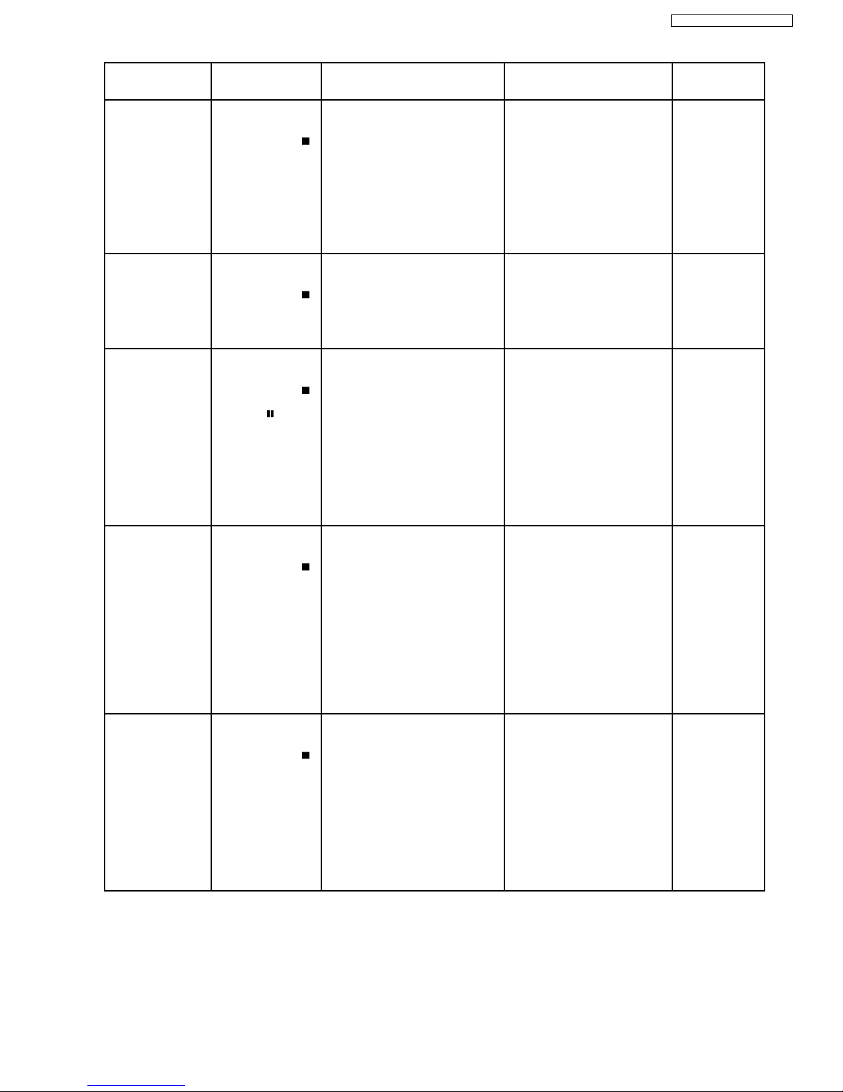
Item Operational
Condition and Key
Function
Details Display TO Exit Mode
Jitter display While the player is
stopped and no disc is
inserted, press and
hold down the
button on the player
and the number
button, “5” on the
remote controller unit.
Jitter display
Measures and displays jitter.
Measurement is repeated every
second. Read error counter starts at 0
at the mode setting, and increased by
one as data read fails at target block. A
small defect is allowed to correct by
retry. Any possibility is counted as one
increment. Repetitive errors after retry
increase by two levels or more.
J*1xxx*2_yyy*3_zz
*4
*1
: Jitter display mode
*2
: Jitter measurement value
*3
: Read error counter
*4
: Focus driving value
Values are shown to one decimal
place in the decimal digit. Focus
driving value is displayed in the
hexadecimal digit.
Press the STOP or
OPEN button.
Error code display While the player is
stopped and no disc is
inserted, press and
hold down the
button on the player
and the number
button, “0” on the
remote controller unit.
Error code display
Displays the latest error code stored in
EEPROM.
DVDnn_F---
*nn: Error history
*--: Error number
DVD 01 FOBF
Press the OPEN
button.
Measurement of laser
current electricity
initialization value
While the player is
stopped and no disc is
inserted, press and
hold down the
button on the player
and the
button
on the remote
controller unit.
Measurement of laser current
electricity initialization value
Memorizes each initialization value of
DVD and CD in EEPROM.
LDO*1_013*2_032
*3
*1
: Laser current electricity
measurement mode
*2
: DVD current electricity value
*3
: CD current electricity value
Values are shown in the decimal
digit. The above example indicates
that the current electricity
initialization value is 13mA at DVD
laser and 32mA at CD laser when
laser is turned on.
Automatically exits
the mode after five
seconds.
Measurement of DVD
laser current electricity
While the player is
stopped and no disc is
inserted, press and
hold down the
button on the player
and the DISPLAY
button on the remote
controller unit.
Measurement of DVD laser current
electricity
Measures DVD laser current electricity
and displays the result together with
the initialization value stored in
EEPROM. After measurement, DVD
laser is lit till the power is turned off (or
goes off when the primary power is
turned off).
LDD*1_012*2_014
*3
*1
: DVD laser current electricity
measurement mode
*2
: Current electricity initialization
value stored in EEPROM
*3
: Present value of current
electricity
Values are shown in the decimal
digit. The above example indicates
that the current electricity
initialization value is 12mA and its
present value is 14mA.
Automatically exits
the mode after five
seconds.
ADSC internal RAM
display
While the player is
stopped and no disc is
inserted, press and
hold down the
button on the player
and the number button
“1” or “2” on the remote
controller unit.
ADSC internal RAM display
Reads and displays the RAM value
inside ADSC. The address is renewed
when the CLEAR key is pressed so
that the values at eleven points appear.
A*1_FB0*2_0000
*3
*1
:ADSC internal RAM display
mode
*2
: Address
*3
: RAM value at displayed
address
Values are shown in the
hexadecimal digit. The above
example indicates that ADSC
value at the address, FB0h is
0000h.
Press the STOP or
OPEN button.
27
SA-VK91DGCS / SA-VK91DGCP
Item Operational
Condition and Key
Function
Details Display TO Exit Mode
Measurement of CD
laser current electricity
While the player is
stopped and no disc is
inserted, press and
hold down the
button on the player
and the number button
“3” on the remote
controller unit.
Measurement of CD laser current
electricity
Measures CD laser current electricity
and displays the result together with
the initialization value stored in
EEPROM. After measurement, CD
laser is lit till the power is turned off (or
goes off when the primary power is
turned off).
LDC*1_032*2_032
*3
*1
: CD laser current electricity
measurement mode
*2
: Current electricity initialization
value stored in EEPROM
*3
: Present value of current
electricity
Values are shown in the decimal
digit. The above example indicates
the current electricity initialization
value is 28mA and its present
value is 26mA when laser is turned
on.
Automatically exits
the mode after five
seconds.
User initialization While the player is
stopped and no disc is
inserted, press and
hold down the
button on the player
and the number button
on the remote
controller unit.
User initialization
The user setting recovers the factory
setting.
“INITIALIZE” -
Region display While the player is
stopped and no disc is
inserted, press and
hold down the
button on the player
and the number
button, “6” on the
remote controller unit.
Region display [srrrxxyzzzz ]
s : Panecon model type
rrr : Panecon release number
x : Syscon generation (45)
y: Syscon model type
zzz: Syscon release number
Automatically exits
the mode after five
seconds.
Firmware version
display
While the player is
stopped and no disc is
inserted, press and
hold down the
button on the player
and the number
button, “7” on the
remote controller unit.
Firmware version display rrr*1_xx*2y*3zzz
*4
*1
: Panel computer release number
*2
: System computer generation
*3
: System computer model type
*4
: System computer release
number
Automatically exits
the mode after five
seconds.
Region and firmware
display
While the player is
stopped and no disc is
inserted, press and
hold down the
button on the player
and the number
button, “8” on the
remote controller unit.
Region and firmware version display _r*1__xx*2y*3zzz
*4
*1
: Region number
*2
: System computer generation
*3
: System computer model type
*4
: System computer release
number
Automatically exits
the mode after five
seconds.
Laser use time While the player is
stopped and no disc is
inserted, press and
hold down the
button on the player
and the
button
on the remote
controller unit.
Laser usage time
Measures each for DVD and CD
respectively.
T1_1234_5678
The numbers in the left show
usage time for DVD laser and
those in the right for CD laser. The
four-digit number is shown by the
ten hours in the decimal digit. The
number after 0000 is 9999.
Automatically exits
the mode after five
seconds.
Reset laser use time While the usage time 1
is displayed, press and
hold down the
button on the player
and the
button
on the remote
controller unit.
Laser usage time reset
Resets both for DVD and CD at once.
T1_0000_0000 Automatically exits
the mode after five
seconds.
Spindle use time While the player is
stopped and no disc is
inserted, press and
hold down the
button on the player
and the
button
on the remote
controller unit.
Spindle motor usage time T2_1234
The four-digit number is shown by
the ten hours in the decimal digit.
The number after 00000 is 99999.
Automatically exits
the mode after five
seconds.
User reset While the player is
stopped and no disc is
inserted, press “STOP”
& “ENTER” on remote
control.
Reset the unit. “DVD RESET” Automatically exits
the mode after five
seconds.
28
SA-VK91DGCS / SA-VK91DGCP
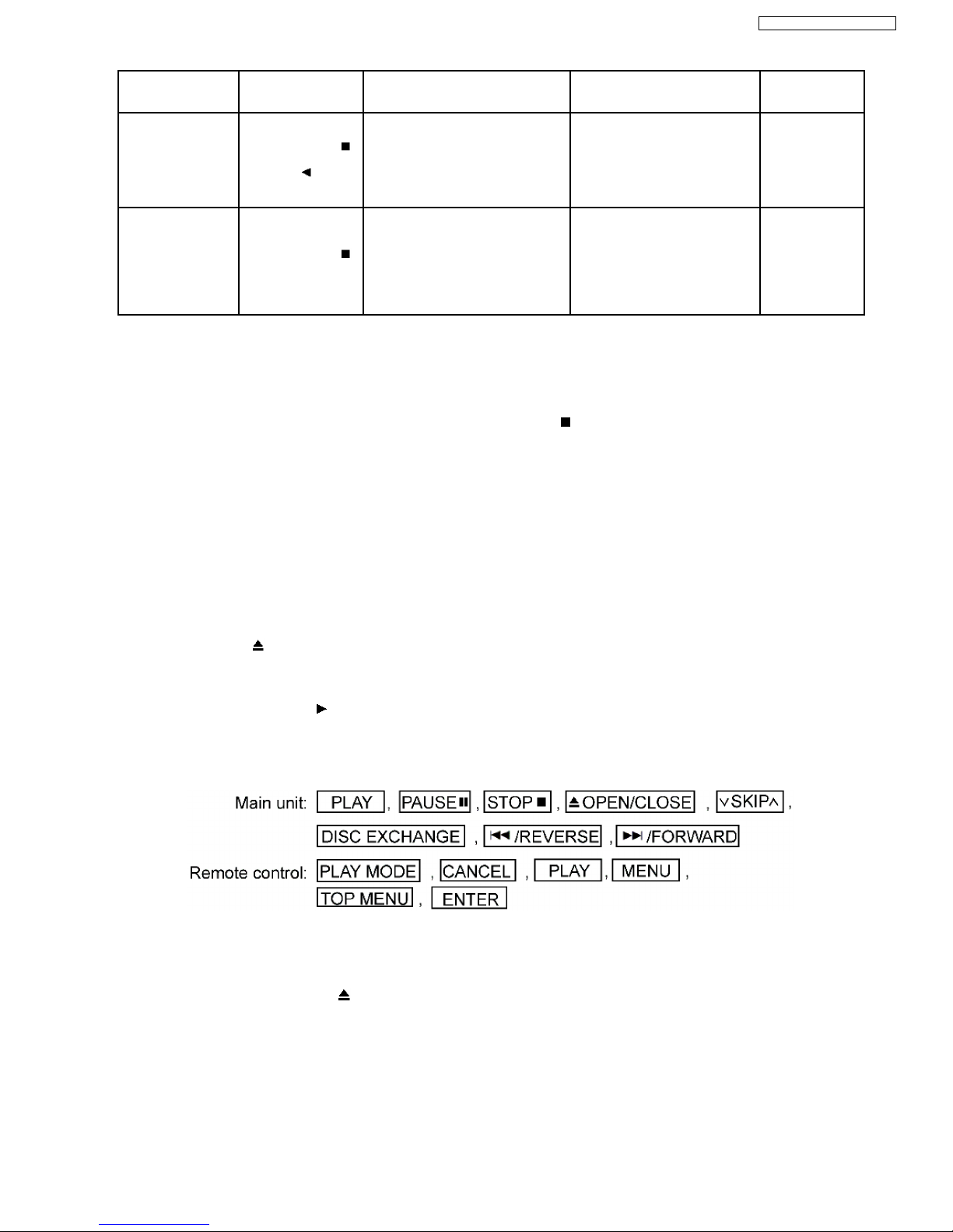
Item Operational
Condition and Key
Function
Details Display TO Exit Mode
Reset spindle use
time
While the usage time 2
is displayed, press and
hold down the
button on the player
and the
button
on the remote
controller unit.
Usage time 2 reset
Spindle motor usage time
T2_0000 Automatically exits
the mode after five
seconds.
Communication error
display
While the player is
stopped and no disc is
inserted, press and
hold down the
button on the player
and the MENU button
on the remote
controller unit.
Displays frequency of communication
errors between system computer firm
IC and mechanical computer IC during
DVD module.
ERR_00/30 Automatically exits
the mode after five
seconds.
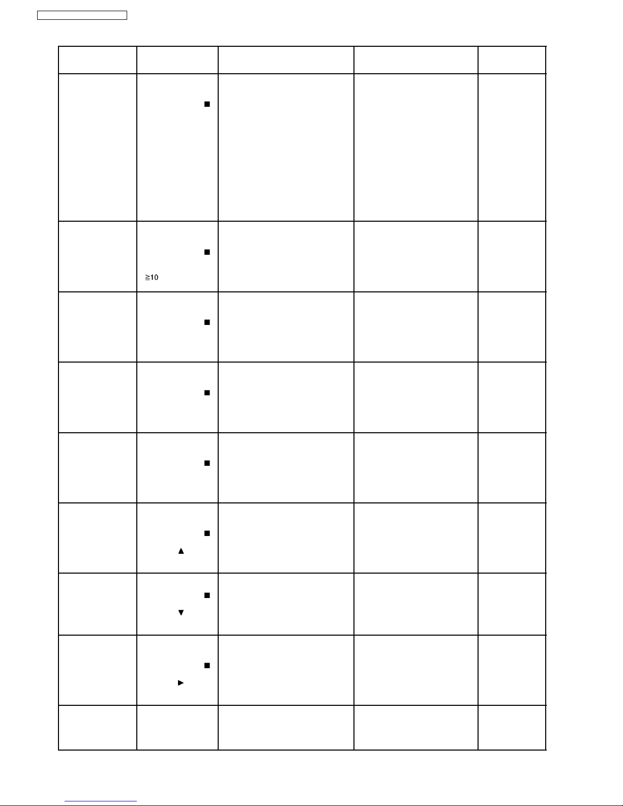
15.7. Tray Lock Function
15.7.1. Setting
· Disc Lock Function
1. With the SELECTOR on DVD/CD and POWER ON, hold down the [
STOP] KEY on the main unit, and then press the
[POWER] KEY on the remote control for 3 seconds to enter to Lock mode A.[_ _ _LOCKED_] will be displayed for 3
seconds, and then current disc will begin playing.
2. In Lock mode A, the following key is disable d.
[OPEN/CLOSE]
· Operation Lock Function
1. With the SELECTOR on DVD/CD and POWER ON, hold down the [CD PLAY] KEY on the main unit, and then press the
[POWER] KEY on the remote control for 3 seconds to enter Lock mode B.
[_ _ _ LOCKED_] will be displayed for 3 second s, and the current disc will begin playing.
2. Lock mode B primarily controls the selector and disc operations, and disenables for the following keys.
Note:
OPEN/CLOSE
button are invalid and the player displays “___LOCKED _” while the lock function mode is entered.
· Prohibiting operation of selector and disk
1. Select the DVD/CD function.
2. Press and hold down the
button on the player and the power button on the remote controller unit for at least three
seconds. (The message, “___LOCKED_” appears when the function is activated.)
Note:
The following button s are invalid and the player display s “___LOCKED_” while the lock function mode is entered.
15.8. Things to Do After Repair
Follow the procedure described below after repair.
1. While the power is on, press the
button to close the tray.
2. Press the power button to turn off the power.
3. Unplug the power cable.
Note:
It is prohibited to unplug the power cable while the tray is opened and to close the tray manua lly.
29
SA-VK91DGCS / SA-VK91DGCP

16 Cautions To Be Taken During Servicing
16.1. Recovery after the dvd player is repaired
· W hen Flash ROM or DVD Module P.C.B. is replaced, carry out the recovery processing to optimize the drive. Playback the
recovery disc to process the recovery automatically.
· Recovery disc (Product number=RFKZD03R005)
· Performing recovery
1. Load the recovery disc (Product number: RFKZD03R005) to the player and run it.
2. Recovery is performed automatically . When it is finished, a message appea rs on the screen.
3. Remove the recovery disc.
4. Turn off the power.
16.2. DVD Player Firmware Version Upgrade Process
Firmware of DVD player may upgrade to conform to improvement of its performance and quality including operational range,
playability of non-standardized discs, etc. The version upgrade disc contains the recovery function, and the recovery disc is not
necessary.
Note:
Version upgrade process cannot be complete if the AC power is cut off due to power failure and other occasions during the
process. If this occurs, replace FLASH ROM IC and restart version upgrade. Version upgrade disc number is informed when
ordered.
16.3. Firmware Version Upgrade Process by Using Disc and Recovery
Process
· Recovery process
· Firmware version upgrade process
Both of the above procedures automatically start when the recovery disc is replaye d.General CD-R disc allows version upgrade
process and recovery process, making version upgrade through disc simple.
Recovery process: Optimization process of player after replacement of FLASH ROM, EEPRO M, or module circuit board
Version upgrade process: Renewal of firmware for improvement of operational range and performance
16.3.1. Self-Diagnosis Function
· Total usage time display (spindle motor, DVD/CD laser)
· ADSC internal RAM display
· Others: Last error count......20 items
Efficiency of failure diagnosis is expected to improve by using the above functions together with the repair process.
[Purpose of Use]
Total usage time display: used for estimating a failure due to exhausted spindle motor, laser, or other parts.
ADSC internal RAM display : used for deciding servo system failure according to servo learning values.
16.4. Using Recovery Disc
16.4.1. Recovery Process
1. Insert the recovery disc (RFKZD03R005) to the player to replay.
2. The recovery process automatically starts, and a message of completion prompts on the screen.
3. Remove the disc.
4. Turn off the power.
16.4.2. Version Upgrade Process
1. Insert the recovery disc to the player to replay.
2. The version of player is automatically checked and prompts if necessary.
3. Select version upgrade process using the cursor keys on the remote controller unit. (Select YES or NO)
4. a. If YES is selected, the process starts.
30
SA-VK91DGCS / SA-VK91DGCP
 Loading...