

Panasonic SAP-XRV96EH, SAP-XRV126EH, SAP-XRV186EH, SAP-FRV96EH, SAP-FTRV126H Operating Instructions
...Page 1
• INSTRUCTION MANUAL
• MANUAL DE INSTRUCCIONES
• MODE D’EMPLOI
• BEDIENUNGSANLEITUNG
Inverter-Controlled
Split System Air Conditioner
Acondicionador de aire de dos unidades
controlado por invertidor
Climatiseur de type séparé contrôlé par
inverseur
Splitsystem-Klimagerät mit InverterSteuerung
SAP-XRV96EH
SAP-XRV126EH
SAP-XRV186EH
SAP-FRV96EH
SAP-FTRV126H
SAP-FTRV186EH
SAP-FTRV246EH
This air conditioner uses the new refrigerant R410A.
SAP-URV96EH
SAP-URV126EH
SAP-URV186EH
SAP-URV246EH
COOL/DRY/HEAT Model
Save These Instructions!
Guarde estas instrucciones
Conserver ce mode d’emploi
Bewahren Sie bitte diese
Bedienungsanleitung auf.
Pub. OI-37.4196.127.0
© SANYO 2010
Page 2

Features
This air conditioner is an inverter type unit that automatically adjusts capability as appropriate. Details on these
functions are provided below; refer to these descriptions when using the air conditioner.
• Microprocessor Controlled Operation
The interior compartment of the remote control
unit contains several features to facilitate
automatic operation, easy logically displayed for
easy use.
• Simple One-touch Wireless Remote Control
The remote control unit has several features to
facilitate automatic operation.
• 24-Hour ON or OFF Timer
This timer can be set to automatically turn the
unit on or off at any time within a 24 hour period.
• 1-Hour OFF Timer
This timer can be set to automatically turn off the
unit at any time after one hour.
• Night Setback
Pressing this button changes the setting of the
room temperature thermostat, allowing you to set
the temperature at whatever level that you find
comfortable.
• Automatic and 3-step Fan Speed
Auto/High/Medium/Low
• Automatic Switching between Cooling and
Heating
This unit automatically switches between cooling
operation and heating operation according to the
difference between the room temperature and the
temperature setting.
• Hot Start Heating System
Right from the start, the air is warm and
comfortable. This system prevents any cold blasts
at the beginning while the heat pump is warming
up, or even defrosting.
• Automatic Restart Function for Power Failure
Even when power failure occurs, preset
programmed operation can be reactivated once
power resumes.
• High Power Operation
If not in Auto Operation, the unit operates at
maximum output for 30 minutes, regardless of the
desired temperature.
The fan speed is 1 step above “High”.
• Anti-Mold Filter
This unit is equipped with an anti-mold filter that
inhibits the growth of mold and bacteria.
• Air Sweep Control
This function moves a flap up and down in the air
outlet, directing air in a sweeping motion around
the room and providing comfort in every corner.
• Auto. Flap Control
This automatically sets the flap to the optimum
position during heating, cooling, and drying
operation.
2
Page 3
Contents
Page
Features............................................................................................................ 2
Product Information........................................................................................... 3
Alert Symbols.................................................................................................... 3
Installation Location .......................................................................................... 4
Electrical Requirements .................................................................................... 4
Safety Instructions............................................................................................. 4
Names of Parts ................................................................................................. 5
Using the Remote Control Unit ....................................................................... 11
Operation with the Remote Control Unit ......................................................... 14
1. Automatic Operation .............................................................................. 14
2. Manual Operation .................................................................................. 15
3. Adjusting the Fan Speed........................................................................ 16
4. Fan Only................................................................................................. 16
5. Night Setback Mode............................................................................... 17
6. HIGH POWER Mode ............................................................................. 18
Special Remarks............................................................................................. 19
Setting the Timer............................................................................................. 20
Using the 1-Hour OFF Timer .......................................................................... 22
Tips for Energy Saving.................................................................................... 22
Adjusting the Airflow Direction ........................................................................ 23
Operation without the Remote Control Unit .................................................... 25
Care and Cleaning.......................................................................................... 25
Troubleshooting............................................................................................... 29
Product Information
If you have problems or questions concerning your Air Conditioner, you will
need the following information. Model and serial numbers are on the nameplate
on the bottom of the cabinet.
Model No. ______________________ Serial No. ____________________
Date of purchase ________________________________________________
Dealer’s address ________________________________________________
Phone number ________________
DECLARATION OF CONFORMITY
This product is marked « » as it satisfies EEC Directive No. 89/336/ EEC,
93/68/EEC, 92/31/EEC and 2006/95/CE.
This declaration will become void in case of mis-usage and/or from non
observance though partial of Manufacturer’s installation and/or operating
instructions.
Alert Symbols
The following symbols used in this manual, alert you to potentially
dangerous conditions to users, service personnel or the appliance:
CAUTION
This symbol refers to a hazard or unsafe
practice which can result in severe
personal injury or death.
This symbol refers to a hazard or unsafe
practice which can result in personal
injury or product or property damage.
3
Page 4
Installation Location
• We recommend that this air conditioner be installed properly by
qualified installation technicians in accordance with the Installation
Instructions provided with the unit.
• Before installation, check that the voltage of the electric supply in your home
or office is the same as the voltage shown on the nameplate.
• Do not install this air conditioner where there are fumes or
flammable gases, or in an extremely humid space such as a
greenhouse.
• Do not install the air conditioner where excessively high heatgenerating objects are placed.
Avoid: To protect the air conditioner from heavy corrosion, avoid installing the
outdoor unit where salty sea water can splash directly onto it or in
sulphurous air near a spa.
Electrical Requirements
1. All wiring must conform to the local electrical codes. Consult your dealer or a
qualified electrician for details.
2. Each unit must be properly grounded with a ground (or earth) wire or
through the supply wiring.
3. Wiring must be done by a qualified electrician.
CAUTION
Safety Instructions
• Read this Instruction Manual carefully before using this air
conditioner. If you still have any difficulties or problems, consult your
dealer for help.
• This air conditioner is designed to give you comfortable room
conditions. Use this only for its intended purpose as described in this
Instruction Manual.
• Never use or store gasoline or other flammable vapor or liquid near
the air conditioner — it is very dangerous.
• This air conditioner has no ventilator for intaking fresh air from
outdoors. You must open doors or windows frequently when you
use gas or oil heating appliances in the same room, which consume
a lot of oxygen from the air. Otherwise there is a risk of suffocation
in an extreme case.
• Do not turn the air conditioner on and off from the power mains
switch. Use the ON/OFF operation button.
• Do not stick anything into the air outlet of the outdoor unit. This is
dangerous because the fan is rotating at high speed.
• Do not let children play with the air conditioner.
• Do not cool or heat the room too much if babies or invalids are
present.
4
Page 5
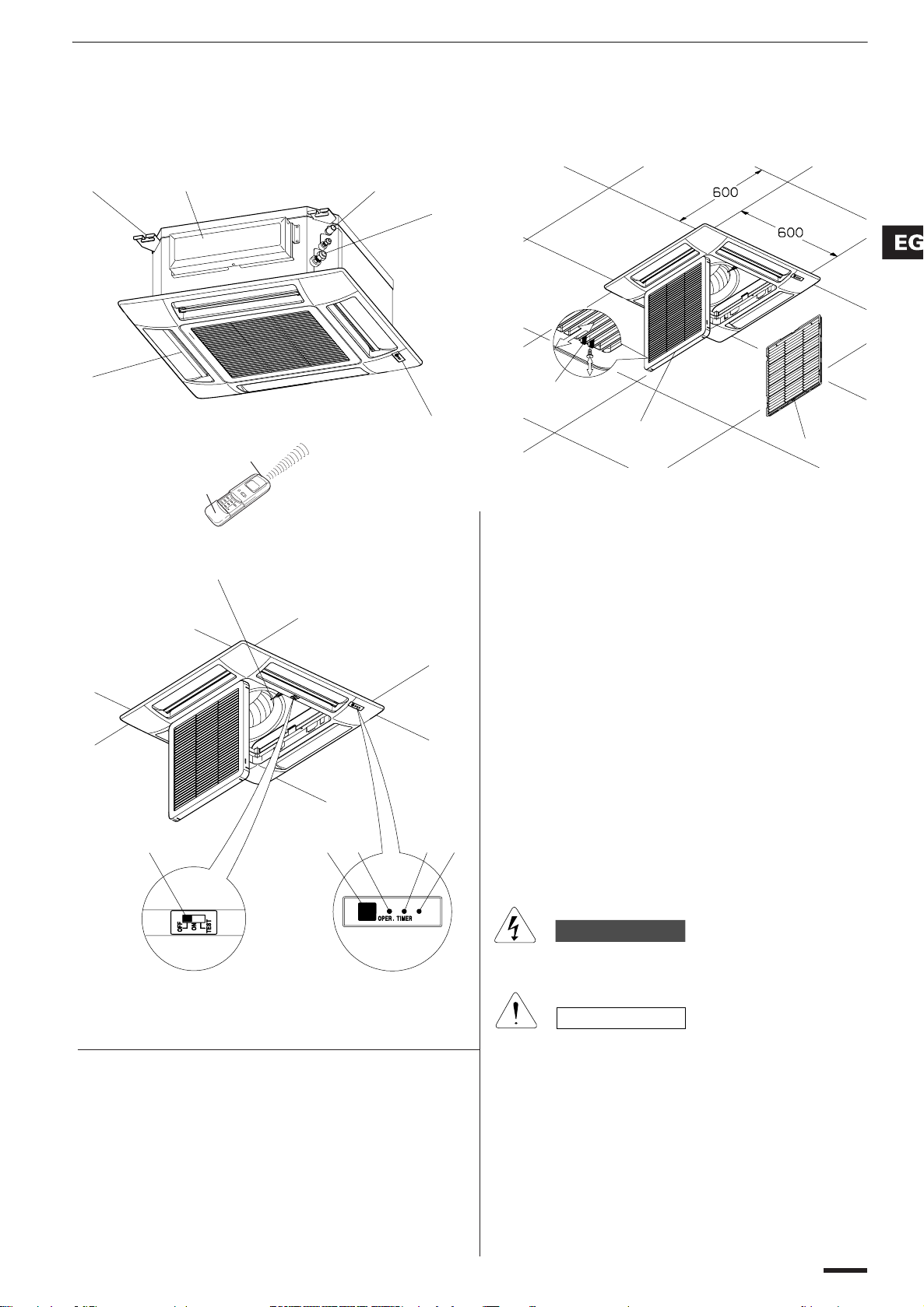
INDOOR UNIT
1. Remote control unit.
2. Sensor: Detects the room temperature around the remote
control unit, the air conditioner is controlled accordingly.
3. Receiver: This section picks up infrared signals from the
remote control unit (Transmitter).
4. Air outlet: Conditioned air is blown out of the air conditioner
through the air outlet (four flaps).
5. Air intake latch, on two sides.
6.
Air intake grille: Air from the room is drawn into this section and
passes through air filter which removes dust.
7. Air filter.
8. Suspension brackets.
9. Refrigerant couplings.
10. Condensate drain connection.
11. Electric junction box.
12. Sensor:
Detects the room temperature around the unit; when
the remote control unit is not active the air conditioner will be
set by the detected temperature.
13. Operation selector.
ON Position: In this position the air conditioner is operating
and controlled by the remote control unit.
Set the selector normally in this position.
OFF Position: Switch the selector to the off position if you
are not going to use the air conditioner for
a few days or longer.
TEST Position: This position is used only for servicing the
air conditioner, so don’t leave the selector in
this position for normal operation.
14. Operation lamp (OPER): This lamp lights when the air
conditioner is running.
15. SERVICE lamp: When a fault occurs in the air conditioner, this
lamp turns on or flashes in combination with the other two
lamps to indicate the type of fault.
16.TIMER lamp: This lamp lights when the system is being
controlled by the timer.
2
1
The OFF position does not disconnect the power. Use the
main power switch to turn off power completely.
WARNING
CAUTION
4
8
10
3
11
3
5
6
7
12
13
14 16
15
9
Names of parts
MODELS XRV
5
Page 6
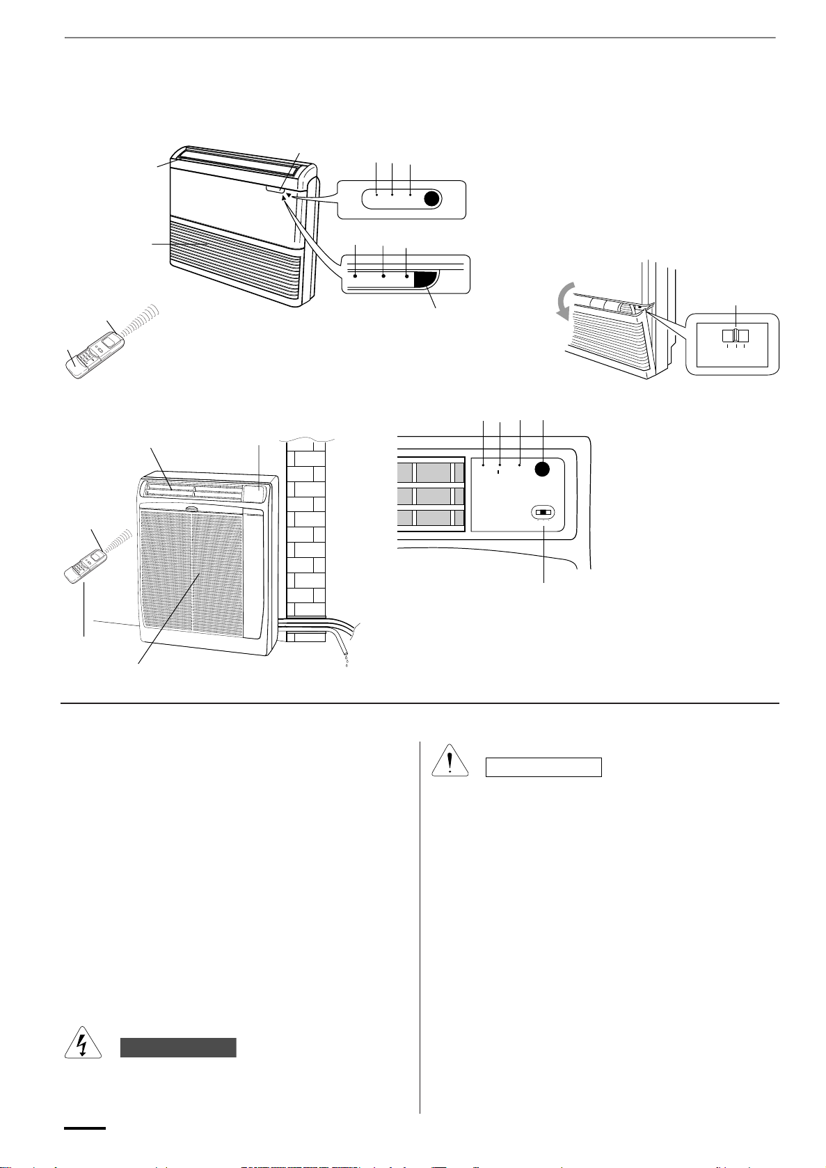
MODELS FTRV-FRV
5
3
4
2
1
3
2
5
9
TIMER
9
TIMER
8
OPERATION
8 7
OPERATION
7
6
5
OFF
ON
TEST
8
7
9
TIMER
OPERATION
5
OFF
ON
TEST
1
4
1. Remote control unit.
2. Sensor: Detects the room temperature around the remote
control unit, the air conditioner is controlled accordingly.
3. Air outlet: Conditioned air is blown out of the air conditioner
through the air outlet.
4.
Air intake: Air from the room is drawn into this section and passes
through air filter which removes dust.
5. Remote control receiver: This section picks up infrared
signals from the remote control unit (Transmitter).
6. Operation selector.
ON Position: In this position the air conditioner is operating
and controlled by the remote control unit.
Set the selector normally in this position.
OFF Position: Switch the selector to the off position if you
are not going to use the air conditioner for
a few days or longer.
6
CAUTION
TEST Position: This position is used only for servicing the
air conditioner, so don’t leave the selector in
this position for normal operation.
7. Operation lamp (OPR): This lamp lights when the air
conditioner is running.
8. SERVICE lamp: When a fault occurs in the air conditioner, this
lamp turns on or flashes in combination with the other two
lamps to indicate the type of fault.
9. TIMER lamp: This lamp lights when the system is being
controlled by the timer.
WARNING
The OFF position does not disconnect the power. Use the
main power switch to turn off power completely.
6
Page 7
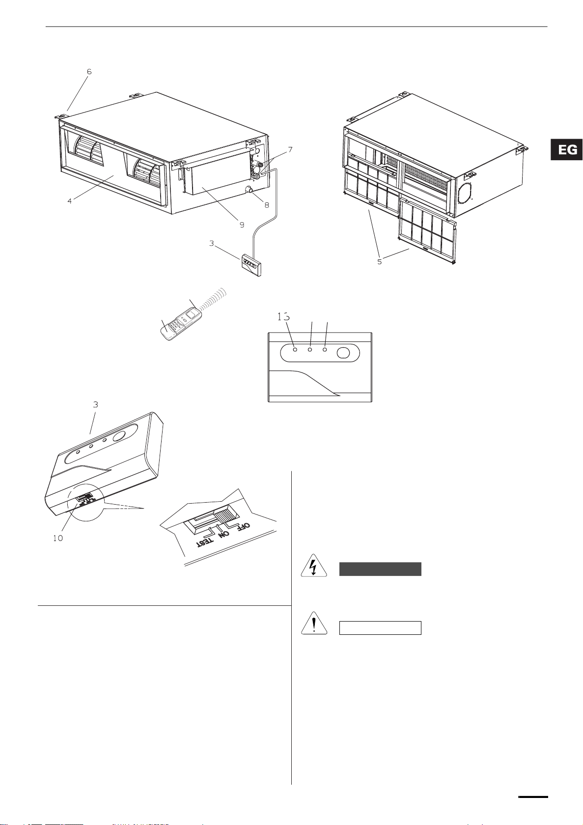
1. Remote control unit.
2. Sensor:
Detects the room temperature around the remote
control unit, the air conditioner is controlled accordingly.
3. Receiver: This section picks up infrared signals from the
remote control unit (Transmitter).
4. Air outlet: Conditioned air is blown out of the air conditioner
through the air outlet (four flaps).
5. Air filter.
6. Suspension brackets.
7. Refrigerant couplings.
8. Condensate drain connection.
9. Electric junction box.
10. Operation selector.
ON Position:
In this position the air conditioner is operating
and controlled by the remote control unit.
Set the selector normally in this position.
OFF Position: Switch the selector to the off position if you
are not going to use the air conditioner for
a few days or longer.
TEST Position: This position is used only for servicing the
air conditioner, so don’t leave the selector in
this position for normal operation.
11. Operation lamp: This lamp lights when the air conditioner is
running.
12. SERVICE lamp: When a fault occurs in the air conditioner, this
lamp turns on or flashes in combination with the other two
lamps to indicate the type of fault.
13.TIMER lamp: This lamp lights when the system is being
controlled by the timer.
2
1
The OFF position does not disconnect the power. Use the
main power switch to turn off power completely.
WARNING
CAUTION
MODELS URV
12
11
13
TIMER
OPERATION
7
Page 8

Displayed when the
time display is set to
12-hour time.
Remote Control Unit (Display)
Displayed when transmitting data
Displayed when indoor unit sensor
is in use
Displayed when setting
temperature
Displayed when temperature is
shown
Displayed when setting timer
Symbols
(1) Operation mode
AUTO .....................................
HEAT ......................................
MILD DRY..............................
COOL.....................................
FAN ........................................
(2) Fan speed
Automatic operation ...............
HIGH .....................................
(4) Timer
24-hour clock with ON/OFF
program Timer........................
ON Timer................................
OFF Timer..............................
1-hour OFF Timer...................
(5) NIGHT SETBACK ..................
(6) Confirmation
of transmission .......................
(7) Auto. flap indication ................
MEDIUM.................................
LOW.......................................
(3) Temperature setting
16–30°C
When set to 28 °C
temperature indication............
8
Flap angle indication ..............
Sweep indication ....................
(8) High power operation .............
Page 9

Remote Control Unit
Tran smitt er
HIGH POWER button
FAN SPEED selector button
FLAP button
ON TIME
setting
buttons
Advance button
Return button
CANCEL button
SENSOR button
Display
Sensor
(Cover closed)
ON/OFF operation button
1 HR. TIMER button
Temperature setting buttons (TEMP.)
MODE selector button
NIGHT SETBACK button
Advance button
Return button
CLOCK button
Time display selector button
OFF TIME
setting
buttons
ADDRESS switch
Temperature display
selector button
NOTE
Tran smitt er When you press the buttons on the remote control unit, the mark appears
Sensor A temperature sensor inside the remote control unit senses the room
Display Information on the operating conditions is displayed while the remote control
ON/OFF operation button This button is for turning the air conditioner on and off.
1 HR. TIMER button
(1-HOUR OFF TIMER)
The illustration above pictures the remote control unit after the cover has
been opened.
in the display to transmit the setting changes to the receiver in the air
conditioner.
temperature.
unit is switched on. If the unit is turned off, FLAP setting and FAN SPEED
setting are not displayed.
: When you press this button, regardless of whether the unit is
operating or stopping, the unit operates for one hour and then shuts
down.
ACL button
9
Page 10
Remote Control Unit (continued)
Temperature setting buttons
(TEMP.)
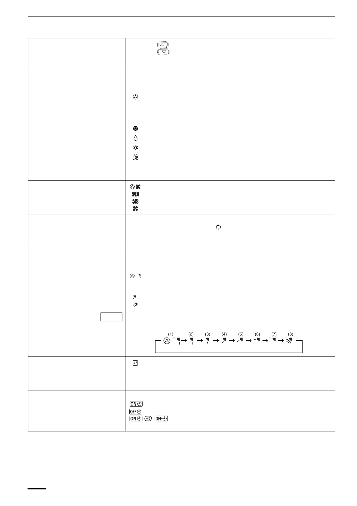
MODE selector button Use this button to select AUTO, HEAT, DRY, COOL or FAN mode.
(AUTO) : When this setting is selected, the air conditioner calculates the
(HEAT) : The air conditioner makes the room warmer.
(DRY) : The air conditioner reduces the humidity in the room.
(COOL) : The air conditioner makes the room cooler.
(FAN) : The air conditioner works only as a circulation fan (except at “M” of the
FAN SPEED selector button : The air conditioner automatically decides the fan speeds.
Press the button to increase the set temperature.
Press the button to reduce the set temperature.
The temperature setting changes by 1 °C or 2 °F each time one of the TEMP.
buttons is pressed.
difference between the thermostat setting and the room temperature
and automatically switches to the ‘‘COOL’’ or ‘‘HEAT’’ mode as
appropriate (except at “M” of the Single/Multiple switch).
Single/Multiple switch).
: High fan speed
: Medium fan speed
: Low fan speed
NIGHT SETBACK button For details, see “5. Night Setback Mode”. When you press this button in the
HEAT, DRY or COOL mode, the mark appears in the display, and the
remote control unit will automatically adjust the set temperature to save
energy.
FLAP button Press this button either to select the setting of the airflow direction to the
(NOT ACTIVE FOR MODELS
URV-FRV)
NOTE
HIGH POWER button : If this button is pressed during HEAT, DRY, COOL or FAN operation,
auto. flap in each mode or one of the six possible positions manually or to
select the sweep function which moves the flap up and down automatically.
: Auto flap setting: If selected in a heating operation, the flap is set to
position (3) in the following chart. If selected in a cooling or dry
operation, the flap is set at position (7) in the following chart.
: The airflow direction can be set manually. (six positions)
: The flap moves up and down automatically.
When you press the FLAP button, the air flow direction will be changed one
by one as follows.
SWEEP
the unit operates at maximum output for 30 minutes, regardless of the
desired temperature.
The fan speed is 1step above ‘‘HIGH’’.
ON TIME/OFF TIME setting
10
buttons
No display: The timer does not operate.
: The air conditioner starts at the set time.
: The air conditioner stops at the set time.
: The air conditioner stops and starts, or starts and stops, at
the set times every day. For details, see “Setting the Timer”.
Page 11

Remote Control Unit (continued)
SENSOR button When you press this button (use a small-tipped object such as a ballpoint
pen), the mark will appear at the display. And the room temperature is
detected by the sensor which is built into the indoor unit and the air
conditioner is controlled accordingly.
NOTE
Temperature Display Selector button
Time Display Selector button This switches the time display between 24-hour time and 12-hour time.
ACL button (ALL CLEAR) Puts the remote control unit into pre-operation status. Always press this
ADDRESS switch • The address switch changes to prevent mixing of signals from remote
S/M (Single/Multiple switch) • Initially, the S/M switch is set to S (Single).
NOTE
NOTE
The remote control unit sends the temperature signal to the air conditioner regularly at five minute
intervals. If the signal from the remote control unit stops for more than 15 minutes due to the loss of
the remote control unit or other trouble, the air conditioner will switch to the temperature sensor which
is built into the indoor unit and control the room temperature. In these cases, the temperature around
the remote control unit may differ from the temperature detected at the air conditioner’s position.
If the remote control is located near a heat source, such as a space heater or in
direct sunlight, press the SENSOR button to switch to the sensor on the indoor unit.
This switches the temperature display between °C and °F.
button after replacing the batteries and setting the S/M switch.
control units when two air conditioners are installed next to each other.
Normally, the address switch is set to A. For more information, please
contact the dealer where you made the purchase.
• Normally, the tabs on the remote control unit should not be bent.
• Set this switch to M (Multiple) for multiple operation.
• Always press ACL button by a thin object such as the tip of a pen after
setting the S/M switch.
When multiple indoor units are used and units in other rooms are already operating,
they will be set to the same mode of operation as the operating indoor units.
How to Install Batteries
ACL button
NOTE
Using the Remote Control Unit
S/M switch
1. Slide the cover in the direction
indicated by the arrow and remove it.
2. Install two AAA alkaline batteries.
Make sure the batteries point in the
direction marked in the battery
compartment.
3. Use a thin object such as the tip of a
pen to press the ACL button.
• The batteries last about six months, depending on how much you
use the remote control unit. Replace the batteries when the remote
control unit’s display fails to light, or when the remote control cannot
be used to change the air conditioner’s settings.
• Use two fresh leak-proof type-AAA alkaline batteries.
• In replacing batteries, follow the instructions as mentioned in the
sub-section “How to Install Batteries”.
• If you do not use the remote control unit more than 1 month, take out
the batteries.
11
Page 12

Using the Remote Control Unit (continued)
RECEIVER
RECEIVER
TRANSMITTER HEAD
REMOTE
CONTROL UNIT
REMOTE
CONTROL UNIT
TRANSMITTER HEAD
RECEIVER
REMOTE
CONTROL UNIT
TRANSMITTER HEAD
RECEIVER
TRANSMITTER
HEAD
REMOTE
CONTROL UNIT
How to Use the Remote
Control Unit
MODELS XRV
Air conditioner
(Indoor unit)
MODELS FTRV-FRV
When using the remote control unit, always point the unit’s transmitter head
directly at the air conditioner’s receiver.
Receiver
Remote control
(Transmitter head)
unit
MODELS URV
12
Page 13

Remote Control Unit
Installation Position
DO NOT • In direct sunlight
The remote control unit may be operated either from a non-fixed position or
from a wall-mounted position. To ensure that the air conditioner operates
correctly, DO NOT install the remote control unit in the following places:
• Behind a curtain or other places where it is covered
• More than 8 m away from the air conditioner
• In the path of the air conditioner’s airstream
• Where it may become extremely hot or cold
• Where it may be subject to electrical or magnetic noise
• Where there is an obstacle between the remote control unit and air
conditioner (since a check signal is sent from the remote control unit every
5 minutes)
Mounting the Remote Control
Unit
Remote control
unit mount
Mounting screws
4 x 16 (included)
When Holding the Remote
Control Unit
Before mounting the remote control unit, press the ON/OFF operation button
at the mounting location to make sure that the air conditioner operates from
that location. The indoor unit should make a beeping sound to indicate that it
has received the signal.
Rear side
Press
Set in
place
• To prevent loss of the remote control
Hole
unit, you can connect the remote
control unit to the mount by passing
a string through the remote control
unit and attachment hole.
To take out the remote control unit, pull it forward.
• When using the remote control unit and during air conditioner operation,
the transmitter on the remote control unit should be pointed toward the
receiver on the indoor unit.
• Make sure that there are no objects between the remote control unit and
receiver which could block the signal.
13
Page 14

Operation with the Remote Control
Unit
1. Automatic Operation
This unit automatically switches between cooling operation and heating
operation according to the difference between the room temperature and the
temperature setting.
STEP 2
STEP 1
NOTE
NOTE
Check that the circuit breaker on the power panel is turned on.
Once mode is selected and the unit is preset by following the steps below,
you can have the air conditioner automatically bring the room to the desired
temperature simply by pressing the ON/OFF operation button.
STEP 1 Press the MODE selector button to .
STEP 2 Press the ON/OFF operation button.
To stop the air conditioner, press the ON/OFF operation button again.
• To change the temperature setting; press the temperature setting buttons
and change the setting to the desired temperature.
14
Page 15

2. Manual Operation
Operation with the Remote Control Unit (continued)
STEP 2
STEP 3
NOTE
STEP 4
STEP 5
Check that the circuit breaker on the power panel is turned on and that the
operation selector of the indoor unit is in the ON position.
If the automatic operation settings of the unit do not meet your needs, press
the setting buttons as described below and change the settings as desired.
STEP 1 Press the MODE selector button and select the desired
mode.
For heating operation →
For dehumidifying operation →
For cooling operation →
For fan only operation →
STEP 2 To start the air conditioner, press the ON/OFF operation
button.
STEP 3 Press the TEMP. setting buttons to change the temperature
setting to the desired temperature.
Adjustable temperature range:
STEP 1
(NOT ACTIVE FOR MODELS
URV-FRV)
30 °C max.
16 °C min.
STEP 4 Set the FAN SPEED selector button to the setting you want.
STEP 5 Press the FLAP button and set the airflow direction as
desired.
(Refer to “Adjusting the Airflow Direction” on page 21.)
To stop the air conditioner, press the ON/OFF operation button again.
or 86 °F max.
60 °F min.
15
Page 16

Operation with the Remote Control Unit (continued)
NOTE
• Choose the best position in the room for the remote control unit, which
also acts as the sensor for room comfort and transmits the operating
instructions. Once you’ve found this best position, always keep the remote
control unit there.
• This appliance has a built-in 5-minute time delay circuit to ensure reliable
operation. When the operation button is pressed, the compressor will start
running within three minutes. In the event of power failure, the unit will
stop.
3. Adjusting the Fan Speed
A. Automatic fan speed Simply set the FAN SPEED selector button to the position.
This automatically sets the best fan speed for the room temperature.
B. Manual fan speed If you want to adjust fan speed manually during operation, just set the FAN
SPEED selector button as desired. [ , , or ]
4. Fan Only
STEP 2
STEP 3
If you want to circulate air without any temperature control, follow these steps:
STEP 1 Press the MODE selector button to switch to the fan mode
.
STEP 2 Press the ON/OFF operation button.
STEP 3 Press the FAN SPEED selector button to select the fan
speed of your choice ( , or ).
STEP 1
16
Page 17

5. Night Setback Mode
Operation with the Remote Control Unit (continued)
Night Setback Mode is used for saving energy.
Press the NIGHT SETBACK button while operation.
The mark appears in the display.
To release the night setback function, press the NIGHT SETBACK button
again.
A. In Cooling and DRY
Mode: ( and )
B. In Heating Mode: ( )
When the night setback mode is selected, the air conditioner automatically
raises the temperature setting 1 °C when 30 minutes have passed after the
selection was made, and then another 1 °C after another 30 minutes have
passed, regardless of the indoor temperature when night setback was
selected. This enables you to save energy without sacrificing comfort. This
function is convenient when gentle cooling is needed.
1°C (2°F)
Setting
temperature
Press the NIGHT
1°C (2°F)
30 min.
30 min.
Time
SETBACK button
When the night setback mode is selected, the air conditioner automatically
lowers the temperature setting 2 °C when 30 minutes have passed after the
selection was made, and then another 2 °C after another 30 minutes have
passed, regardless of the indoor temperature when night setback was
selected. This enables you to save energy without sacrificing comfort. This
function is convenient when gentle heating is needed.
Setting
temperature
Press the NIGHT
SETBACK button
30 min.
2°C (4°F)
30 min.
2°C (4°F)
Time
17
Page 18

6. HIGH POWER Mode
Operation with the Remote Control Unit (continued)
HIGH POWER mode can be used to increase the output of the indoor unit for
all operation modes except automatic operation.
Press the HIGH POWER button.
The mark appears in the display.
To cancel, press HIGH POWER button again.
• When the HIGH POWER button is pressed, the unit operates at maximum
output for 30 minutes, regardless of the desired temperature. The fan
speed is 1 step above “High”.
• HIGH POWER Mode cannot be used when the operation mode is
Automatic Operation.
NOTE
• When set to High fan speed during heating operation, the
fan runs at High fan speed even though the mark is
displayed.
• Depending on the operating conditions, the fan speed may
be increased by a small amount only.
18
Page 19

Special Remarks
‘‘DRY’’ ( ) Operation
How it works? • Once the room temperature reaches the level that was set, the unit’s
operation frequency is changed automatically.
• During DRY operation, the fan speed automatically runs at lower speed for
providing a comfortable breeze.
• ‘‘DRY’’ operation is not possible if the indoor temperature is 15 °C or less.
Heating ( ) Operation
Heating performance • Because this air conditioner heats a room by drawing in the heat of the
outside air (heat pump system), the heating efficiency will fall off when the
outdoor temperature is very low. If sufficient heat cannot be obtained with
this air conditioner, use another heating appliance together with it.
Defrosting • When the outdoor temperature is low, frost or ice may form on the heat
exchanger coil, reducing heating performance. When this happens, a
microcomputer defrosting system operates. At the same time, the fan on
the indoor unit stops and the OPERATION lamp lights red and orange
alternately until defrosting is completed. Heating operation restarts after
several minutes. (This interval will vary slightly depending upon the
outdoor temperature and the way in which frost forms.)
Cold draft prevention • For several minutes after the start of heating operation, the indoor fan runs
Power failure during
operation
Clicking Sound
Clicking sound is heard from
the air conditioner
Remote Control Unit
at a lower speed until the indoor heat exchanger coil has warmed up
sufficiently. However, the fan may remain stopped when the room
temperature is low. This is because the COLD DRAFT PREVENTION
SYSTEM is in operation.
• In the event of power failure, the unit will stop. When the power is
resumed, the unit will restart automatically within five minutes by the
remote control unit.
• In heating or cooling operation, any plastic parts may expand or shrink due
to a sudden temperature change. In this event, a clicking sound may occur.
This is normal, and the sound will soon disappear.
• The remote control unit sends the setting condition to the air conditioner
regularly at five minute intervals.
19
Page 20

Setting the Timer
NOTE
1. How to set the present
time
In the descriptions below, the following settings are used for the temperature
and time indicator selector button on the bottom front section of the remote
control.
• Temperature: °C
• Time: AM, PM
(Example) To set to 10:30 pm.
Operation Indication
1. Press the CLOCK button once if
the time indicator is not flashing.
2. Press the Advance, Return ( ,
) button until PM 10:30 is
displayed.
3. Press the CLOCK button again. This completes the setting of the
The time indication alone flashes.
The time can be set in 1-minute
increments. Holding down the
button advances the time rapidly in
10-minute increments.
current time.
2. How to set the OFF time
20
(Example) To stop the air conditioner at 11:00 am.
1. Press the OFF TIME setting
button once.
2. Press the Advance, Return ( ,
) button until AM 11:00 is
displayed.
3. Wait a few seconds, and then
the setting is complete.
The timer indication is
displayed, and the present OFF
time is shown.
The timer indication blinks.
The time can be set in 10-minute
increments. Holding down the
button advances the time rapidly in
10-minute increments.
The timer indication stops
blinking and the present time is
displayed.
Page 21

Setting the Timer (continued)
3. How to set the ON time
4. How to set DAILY ON/OFF
REPEAT timer
(Example) To start operation at 7:10 am.
Operation Indication
1. Press the ON TIME setting
button once.
The timer indication is
displayed, and the present ON time
is shown.
2. Press the Advance, Return ( ,
) button until AM 7:10 is
displayed.
The timer indication blinks.
The time can be set in 10-minute
increments. Holding down the
button advances the time rapidly in
10-minute increments.
3. Wait a few seconds, and then
the setting is complete.
The timer indication stops
blinking and the present time is
displayed.
(Example) To start operation at 7:10 am. and stop the air conditioner at 11:00
am.
10:30 pm.
Present time
7:10 am.
ON
11:00 am.
OFF
1. Set the timer ON/OFF times as
shown in 2-1, 2, 3 and 3-1, 2, 3.
NOTE
• The ON/OFF combination timer uses the current time as
the reference, and it is activated starting from whichever
set time comes first.
• With the ON/OFF combination timer, the settings are
repeated every day.
• You can check the timer ON/OFF times after you have set
them by pressing the ON TIME and OFF TIME setting
buttons.
To cancel a timer program • Press the CANCEL button.
• When either an ON or OFF timer is to be canceled, press the button
corresponding to the timer whose program is to be canceled, and then
press the CANCEL button.
NOTE
• The airflow direction, fan speed and temperature setting can be changed
after a timer program has been set even when the unit is stopped. Even
when operation is stopped during an ON timer program, the unit will start
operating when the set time is reached provided that the program is not
canceled.
• When the ON timer and OFF timer are set to the same time, the timer
operates as if it is turned off.
The present time 10:30 pm. and
are displayed.
21
Page 22

Using the 1-Hour OFF Timer
1. 1-Hour OFF Timer This function causes the unit to operate for one hour and then stop,
regardless of whether the unit is on or off when this button is pressed.
The indicator in the display indicates that this function is operating.
Setting procedure:
Regardless of whether the unit is operating or stopped, press the 1 HR.
TIMER button.
appears in the display.
Cancellation procedure:
Press the ON/OFF operation button to turn the unit off, wait for the unit to stop
operating, and then press the ON/OFF operation button again.
The 1-Hour Timer function is now cancelled and the unit operates normally.
NOTE
2. Operation together with the
DAILY ON/OFF REPEAT Timer
Do not • Block the air intake and outlet of the unit. If they are obstructed, the
Do • Always try to keep the air filter clean. (Refer to “Care and Cleaning”.) A
• If, while the 1-Hour Timer function is operating, the 1HR. TIMER button is
pressed once to cancel the function and then again, the unit continues to
operate for one hour from that point in time and then stops.
• It is not possible to use the OFF Timer and 1-Hour OFF Timer together.
Whichever function is set last takes precedence. If the 1 HR. TIMER
button is pressed while the TIMER OFF function operates, the OFF Timer
is cancelled and the unit will stop operating one hour later.
The 1-Hour OFF Timer setting is given priority over the DAILY ON/OFF
REPEAT setting.
Tips for Energy Saving
unit will not work well, and may be damaged.
• Let direct sunlight into the room. Use sunshades, blinds or curtains. If the
walls and ceiling of the room are warmed by the sun, it will take longer to
cool the room.
clogged filter will impair the performance of the unit.
• To prevent conditioned air from escaping, keep windows, doors and any
other openings closed.
22
Page 23

Adjusting the Airflow Direction
This air conditioner is equipped with auto flaps.
You can set the airflow direction using the remote control unit.
FLAPS
MODELS XRV
OFF
6
35
A. Sweep function
The flap starts moving up and down to
deliver air over the sweep range.
C. Auto flap function
The flap is set to the recommended
position.
NOTE
SWEEP
COOL
and
DRY
SWEEP
HEAT
B. Setting the airflow manually
Referring to the above illustration, use the
FLAP button to set the airflow direction
within the range used during the heating,
cooling, or dehumidifying operation.
• The flap automatically closes when the unit is off.
• During the heating operation, the fan speed will be very low and the flap
will be in the horizontal position (position ) until the air being blown out
of the unit begins to warm. Once the air warms up, the flap position and
fan speed change to the settings specified with the remote control.
CAUTION
• Use the FLAP button on the remote control to adjust the position of
the flap. If you move the flap by hand, the flap position according to
the remote control and the actual flap position may no longer match.
If this should happen, shut off the unit, wait for the flap to close, and
then turn on the unit again; the flap position will now be normal
again.
• Do not have the flap pointed down during cooling operation.
Condensation may begin to form around the air vent and drip down.
23
Page 24

VERTICAL VANE
for heating and deumidifyngfor cooling
HOW TO ADJUST THE FLAP DIRECTION
Make sure that the remote control unit has been turned on.
Press the FLAP button to select the sweep function or to choose
one of the six positions of the flap.
HORIZONTAL (manual)
The horizontal air flow can be adjusted by moving the vertical
vanes to the left or right, as indicated in the following figures for
each model.
Set vertical vanes to the front position during COOLING/DRY operation if humidity is high.
If the vertical vanes are set to the left-most or right-most position, condensation will form around the air outlet
and drip off.
CAUTION
VERTICAL VANE
VERTICAL VANE
FLAP
HOW TO ADJUST THE FLAP DIRECTION
COOL and DRY
HEAT
SWEEP
SWEEP
MODELS FRV-FTRV
VERTICAL (with remote control unit) FTRV
6
5
4
3
2
A. Sweep function
The flap starts moving up and down to
deliver air over the sweep range.
1
60°
4
0
°
OFF
B. Setting the airflow manually
Referring to the above illustration, use the
FLAP button to set the airflow direction
60°
40
°
O
FF
within the range used during the heating,
cooling, or dehumidifying operation.
NOTE • The flap automatically closes when the unit is off.
• During the heating operation, the fan speed will be very low and the
flap will be in the horizontal position (position 6) until the air being
blown out of the unit begins to warm. Once the air warms up, the flap
position and fan speed change to the settings specified with the
remote control.
CAUTION
• Use the FLAP button on the remote control to adjust the position of
the flap. If you move the flap by hand, the factual flap position and the
flap position on the remote control may no longer match. If this
should happen, shut off the unit, wait for the flap to close, and then
turn on the unit again; the flap position will now be normal again.
• Do not have the flap pointed down during cooling and drying
operation. Condensation may begin to form around the air vent and
drip down.
VERTICAL (manual) FRV
Hold the end of the flap and move it up and down to adjust the vertical air flow.
24
Page 25

OPERATION
SELECTOR
MODELS XRV
TEST
OFF
ON
TIMER
OPERATION
OPERATION
SELECTOR
OPERATION
SELECTOR
OPERATION
SELECTOR
Operation without the Remote
Control Unit
If you have lost the remote control unit or it has trouble, follow the steps
below.
1. When the air conditioner is not running
If you want to turn on the air conditioner, switch the operation selector to
the OFF position, and then to the ON position.
NOTE The set temperature and fan speed are automatically set at the
last selection before stopping.
2. When the air conditioner is running
If you want to turn off the air conditioner, switch the operation selector to
the OFF position.
MODELS FTRV
MODELS FRV
OFF
ON
TEST
MODELS URV
Care and Cleaning
1. For safety, be sure to turn the air conditioner off and also to
disconnect the power before cleaning.
2. Do not pour water on the indoor unit to clean it. This will damage the
internal components and cause an electric shock hazard.
Casing and Grille (Indoor Unit) Clean the casing and grille of the indoor unit with a vacuum cleaner brush, or
wipe them with a clean, soft cloth.
If these parts are stained, use a clean cloth moistened with a mild liquid
detergent. When cleaning the grille, be careful not to force the vanes out of
place.
CAUTION
1. Never use solvents, or harsh chemicals when cleaning the indoor
unit. Do not wipe the plastic casing using very hot water.
2. Some metal edges and the fins are sharp and may cause injury if
handled improperly; be especially careful when you clean these
parts.
3. The internal coil and other components of the outdoor unit must be
cleaned every year. Consult your dealer or service center.
25
Page 26

Care and Cleaning (continued)
1.Remove the screw on each side out of the latch using a
screwdriver.
2.Press on the two latches of the air intake grille with your thumbs
in the direction of the arrow to open the grille.
3.Open the air intake grille downward.
4.Remove the air filter from the air intake grille.
5.Use a vacuum cleaner to remove light dust. If there is sticky
dust on the filter, wash the filter in lukewarm, soapy water, rinse
it in clean water, and dry it.
3.Insert the filter correctly again inside the grille, close the grille
letting the latches slide toward the outside and fix again the
latch with the screw on both sides.
AIR FILTER
The air filter should be cleaned at least once every six months or
more frequently; it depends on the real operation conditions.
LATCH
SCREW
AIR INTAKE GRILLE
AIR FILTER
HOW TO REMOVE THE AIR INTAKE GRILLE
GRILLE
STRING
1.Detach the safety string from the frame (remember to attach it
again after cleaning or maintenance).
2.
Open the air intake grille
, hold it on and pull it toward you to
detach the two guides.
3.
Clean the grille gently using a soft sponge, or the like. Then
dry it with care.
Neutral detergent may be used to remove stubborn dirt. Then
rinse thoroughly with water and dry it.
ADDITIONAL MAINTENANCE
The inspection or replacement of internal components involve
the removal of the condensate drain pan.
Some metal edges and the vanes of heat exchanger are sharp and
may cause injury if handled improperly; be especially careful when
you clean these parts.
CAUTION
HOW TO REMOVE THE CONDENSATE DRAIN PAN
RUBBER CORK
CONNECTORS
CONDENSATE DRAIN PAN
CLIPS (2)
SUPPORT
PLATE (2)
SCREW (4)
SPECIAL SCREW (4)
1.Open the air intake grille.
2.Drain the condensate water into a bucket trough the rubber
cork that should be soon closed.
3.Remove the frame-grille assembly by loosening the four special
screws with washer; you can utilise the two clips that fix the
frame to the unit.
4.Disconnect the electrical connectors between the frame-grille
assembly and the unit.
5.Remove the four screws of the two support plates.
6.Grasp the two support plates, remove with care the condensate
drain pan and clean it inside, if necessary.
7.Once finished the maintenance, reassemble the pan, aligning
the side with the hole for condensate drain and the side with the
pump; insert the connectors of the unit into the proper hole in
the pan.
8.Fix again the four screws of the support plates and the frame
group aligning the corner from which the wires exit and the
corner with the connectors of the unit.
9.Mount the air intake grille along with the filter; be sure that the
safety string has been attached and that the latch screw has
been fixed on both sides.
MODELS XRV
26
Page 27

MODELS FTRV-FRV
The air filter should be cleaned at least once every six months or
more frequently; it depends on the real operation conditions.
HOW TO REMOVE THE FILTER
1.
2.
FILTER CLEANING
Use a vacuum cleaner to remove light dust. If there is
sticky dust on the filter, wash the filter in lukewarm, soapy
water, rinse it in clean water, and dry it.
AIR FILTER
The air filter behind the air intake grille should be checked and cleaned at least once every two weeks.
HOW TO REMOVE THE FILTER
T
N
2
1
1.Grasp both ends of the air intake grille and pull to open it.
2.Hold the air filter and pull it upward. Clean the air filter.
3.When replacing the filter, make sure that the FRONT mark is facing you. Reinsert the filter into place and close the air
intake grille.
HOW TO REMOVE THE FILTER
Hold the air filter by the tab at the
top and then pull upwards. Clean the
air filter and replace it.
O
R
F
3
MODELS URV
Air Filter
27
Page 28

"AIR CLEAN" FILTER (only for FTRV models)
●
The air filter is to be added by springs to the standard filter.
●
It is made of two layers:
- the first layer consists in a synthetic honey comb high efficiency media to remove the dust and purifing the air.
- the second layer in charcoal media deodorizing the ambient air.
How to install the "Air clean" filter.
1. Open the unit intake air grille and pull out the standard air filter.
2. Apply on the rear side of the filter the two spings supplied with the accessory.
3. Fix the "air clean" filter by the springs.
4. Insert the two air filters one over the other and close the intake grille.
REAR SIDE OF
ANTI-MOLD FILTER
SPRING
“AIR CLEAN” FILTER
(HIGH EFFICIENCY
HONEYCOMB AND
CHARCOAL MEDIA)
(ACCESSORY SUPPLIED ON REQUEST)
28
Page 29

Troubleshooting
If your air conditioner does not work properly, first check the following points before requesting service. If it still does
not work properly, contact your dealer or service center.
Trouble Possible Cause Remedy
Air conditioner does not run at all. 1. Power failure. 1. Restore power.
2. Leakage circuit breaker tripped.
3. Line voltage is too low. 3. Consult your electrician or dealer.
2. Contact service center.
4. Batteries in remote control unit
have run down.
OPERATION lamp blinks and air
conditioner does not operate.
Compressor runs but soon stops. Obstruction in front of condenser coil. Remove obstruction.
Poor cooling (or heating)
performance.
Clicking sound is heard from the air
conditioner.
Trouble in system. Contact service center.
1. Dirty or clogged air filter. 1. Clean air filter to improve airflow.
2. Heat source or many people in
room.
3. Doors and/or windows are open. 3. Shut them to keep the heat (or
4. Obstacle near air intake or air
discharge port.
5. Thermostat is set too high for
cooling (or too low for heating).
6. (Outdoor temperature is too low for
heating.)
In heating or cooling operation, any
plastic parts may expand or shrink
due to a sudden temperature change.
In this event, a clicking sound may
occur.
4. Replace batteries.
2. Eliminate heat source if possible.
cold) out.
4. Remove it to ensure good airflow.
5. Set the temperature lower (or
higher).
6. (Consult your dealer or try to use
another heat appliance.)
This is normal, and the sound will
soon disappear.
OPERATION lamp lights but outdoor
unit will not run.
The use of cellular phones near the
air conditioner may cause
disturbance to its normal operation.
1. Turn off the power then restart the
air conditioner after a while.
2. Consult your dealer.
29
Page 30

INFORMATION FOR CORRECT DISPOSAL OF THE PRODUCT IN ACCORDANCE WITH THE EUROPEAN DIRECTIVE
EG
2002/96/EC
At the end of its working life this equipment must not be disposed of as an household waste.
It must be taken to special local community waste collection centres or to a dealer providing this service.
Disposing of an electrical and electronic equipment separately avoids possible negative effects on the environment and human
health deriving from an inappropriate disposal and enables its components to be recovered and recycled to obtain significant
savings in energy and resources.
In order to underline the duty to dispose of this equipment separately, the product is marked with a crossed-out dustbin.
ADVERTENCIA PARA LA ELIMINACIÓN CORRECTA DEL PRODUCTO SEGÚN ESTABLECE LA DIRECTIVA EUROPEA
ES
2002/96/CE
Al final de su vida útil, este equipo no debe eliminarse junto a los desechos domésticos.
Debe entregarse a centros específicos de recogida diferenciada locales o a distribuidores que facilitan este servicio.
Eliminar por separado un equipo eléctrico y electrónico significa evitar posibles consecuencias negativas para el medio ambiente
y la salud derivadas de una eliminación inadecuada y permite reciclar los materiales que lo componen, obteniendo asi un ahorro
importante de energía y recursos.
Para subrayar la obligación de eliminar por separado estos equipos, en el producto aparece un contenedor de basura tachado.
AVERTISSEMENT POUR L’ELIMINATION CORRECT DU PRODUIT AUX TERMES DE LA DIRECTIVE EUROPEENNE
F
2002/96/CE
Au terme de son utilisation cet équipement ne doit pas être éliminé avec les ordures ménagères.
Le produit doit être remis à l’un des centres de collecte sélective locaux ou auprès des revendeurs assurant ce service.
Eliminer séparément un équipement électrique et électronique permet d’éviter des potentielles retombées négatives pour l’environnement et la santé humaine dérivant d’une élimination incorrect et permet de récupérer les matériaux qui le composent dans
le but d’une économie importante en termes d’énergie et de ressources.
Pour rappeler l’obligation d’éliminer séparément ces équipements, le produit porte le symbole d’un caisson à ordures barré.
HINWEIS FÜR DIE KORREKTE ENTSORGUNG DES PRODUKTS IN ÜBEREINSTIMMUNG MIT DER EUROPÄISCHEN
D
RICHTLINIE 2002/96/EG
Am Ende seiner Nutzzeit darf dieses Gerät nicht zusammen mit dem Hausmüll beseitigt werden.
Es darf zu den örtlichen Sammelstellen oder zu den Fachhändlern, die einen Rücknahmeservice anbieten, gebracht werden.
Die getrennte Entsorgung eines elektrischen und elektronischen Gerätes vermeidet mögliche negative Auswirkungen auf die
Umwelt und die menschliche Gesundheit, die durch eine nicht vorschrichtsmäßige Entsorgung bedingt ist. Zudem ermöglicht wird
die Wiederverwertung der Materialen, aus denen sich das Gerät zusammensetzt, was wiederum eine bedeutende Einsparung an
Energie und Ressourcen mit sich bringt
Zur Erinnerung an die Verpflichtung, die diese Geräte getrennt zu beseitigen, ist das Produkt mit einer durchgestrichen Mülltonne
gekennzeichnet.
Page 31

Do not vent R410A into atmosphere: R410A is a fluorinated greenhouse gas, covered by Kyoto
Protocol, with a Global Warming Potential (GWP) = 1975.
No expulsar R410A a la atmósfera: el R410A es un gas fluorado de efecto invernadero,
cubierto por el protocolo de Kyoto, con potencial de calentamiento global (GWP) = 1975.
Ne déchargez pas R410A dans l'atmosphère : R410A est un gaz fluoré à effet de serre, couvert par le protocole de Kyoto, avec un potentiel de chauffage global (GWP) = 1975.
Zerstreuen Sie R410A in Atmosphäre nicht: R410A ist ein fluoriertes Gas, abgedeckt durch
Kyoto Protokoll, mit einem globalen wärmenden Potential (GWP) = 1975.
EG
F
D
ES
F-GAS Regulation (EC) No. 842/2006
Page 32

S.A.C. - Printed in Italy
SANYO Sales & Marketing Europe GmbH
Via Bisceglie, No. 76
20152 Milano, Italy
 Loading...