

Panasonic SAPM-21-E, SAPM-21-EB, SAPM-21-EG Service manual
A
r
r
CD Stereo System
SA-PM21E
SA-PM21EB
SA-PM21EG
Colour
(S)... Silver Type
ORDER NO. MD0501014C2
Specification
n Amplifier Section
RMS Output Power both channel driven
10% Total harmonic distortion
1 kHz (Low channel) 15 W per channel (6 Ω)
8 kHz (High channel) 5 W per channel (6 Ω)
Total Bi-Amp power 20 W per channel
Output impedance
Headphone 16 - 32 Ω
n FM Tuner Section
Frequency range 87.50 -108.00 MHz
(50 kHz step)
Sensitivity 1.5 µV (IHF)
S/N 26 dB 1.25 µV
ntenna terminals 75 Ω (unbalanced)
n AM Tuner Section
Frequency range 522 - 1629 kHz (9 kHz steps)
520 - 1630 kHz (10 kHz steps)
Sensitivity
S/N 20 dB (at 999 kHz) 500 µV/m
n Cassette Deck Section
Track system 4 track, 2 channel
Heads
Record/playback Solid permalloy head
Erasure AC erase head
Motor DC servo moto
Recording system AC bias 100 kHz
Erase system AC erase 100 kHz
Tape speed 4.8 cm/s
Overall frequency response (+3 dB, -6 dB) at DECK OUT
NORMAL 35 Hz - 14 kHz
S/N RATIO 50 dB (A weighted)
Wow and flutter 0.08% (WRMS)
Fast forward and rewind time Approx. 120 seconds with C-60
cassette tape
n CD Section
Disc played
CD/MP3/CD-R/RW 8cm/12cm
Bit rate
MP3 32kbps - 320kbps
Sampling frequency
CD 44.1 kHz
MP3 32 kHz, 44.1 kHz, 48 kHz
Decoding 16 bit linea
Pickup
Beam source / wavelength Semiconductor laser / 780nm
Number of channels Stereo
Wow and flutter Below measurable limit
Digital filter 8fs
© 2005 Matsushita Electric Industrial Co. Ltd.. All
rights reserved. Unauthorized copyin g and
distribution is a violation of law.
SA-PM21E / SA-PM21EB / SA-PM21EG
D/A converter MASH (1 bit DAC)
Frequency response 20Hz - 20 kHz (+1, -2dB)
n General
Power supply AC 230 V, 50 Hz (E,EG)
AC 230 - 240 V, 50 Hz (EB)
Power consumption 62 W
Dimensions (W x H x D) 165 mm x 228 mm x 315.6 mm
Mass 3.8 kg
Power consumption in standby
mode
0.8 W
Notes :
1. Specifications are subject to change without notices. Mass and
dimensions are approximate.
2. Total harmonic distortion is measured by the digital spectrum
analyzer.
n System : SC-PM21E-S Music center: SA-PM21E-S
Speaker: SB-PM21E-MJ
n System : SC-PM21EB-S Music center: SA-PM21EB-S
Speaker: SB-PM21E-MJ
n System : SC-PM21EG-S Music center: SA-PM21EG-S
Speaker: SB-PM21E-M
CONTENTS
Page Page
1 Safety Precautions
1.1. GENERAL GUIDELINES
2 Caution for AC Mains Lead
3 Before Repair and Adjustment
4 Protection Circuitry
5 Handling the Lead-free Solder
5.1. About lead free solder (PbF)
6 Precaution of Laser Diode
7 Handling Precautions For Traverse Deck
8 Accessories
9 Operation Procedures
10 Information on CD & MP3
11 Assembling and Disassembling
11.1. Disassembly flow chart
11.2. Disassembly of Side Panel L & R
11.3. Disassembly of Top Cabinet Unit
11.4. Disassembly of Deck Mechanism and Tape Eject P.C.B
11.5. Disassembly of Headphone P.C.B
11.6. Disassembly of Front Panel Assembly
11.7. Disassembly of Panel P.C.B
11.8. Disassembly of Rear Cabinet
11.9. Disassembly of Tuner Pack
11.10. Disassembly of Main P.C.B
11.11. Disassembly of Powe r P.C.B
11.12. Disassembly of Speak er Termi nal P.C.B
11.13. Disassembly of Trans forme r P.C.B
11.14. Disassembly of CD Mechanism
11.15. Checking Procedure for Each Major P.C.B.
11.16. Procedures of Repla cing Trave rse Base (Unit), Driving
Gear, and Cam Gear (CD Mechanism Unit)
11.17. Procedures for Repla cing Optica l Pickup (CD Mechanism
Unit)
11.18. Procedures for Repla ceme nt Traverse Gear A and
Traverse Gear B (CD Mechanism Unit)
4
4
5
6
6
6
6
7
8
9
10
11
12
12
13
13
13
14
14
15
15
15
16
16
17
17
18
19
19
22
23
11.19. Procedure for Repla cing Casse tte Holde r
11.20. Procedure for Repla cing Pinch Roller and Head Block
(Cassette Mechanism Unit)
11.21. Procedure for Repla cing Motor , Capstan Belt A, Capst an
Belt B, and Winding Belt (Cassette Mechanism Unit)
11.22. Procedure for Repla cing Parts on Mech anism PCB
11.23. Handling of casse tte tape jam
12 Service Positions
12.1. Checking procedure
12.2. Checking the major P.C.B.
13 Self Diagnostic Function
13.1. Self-diagnosis Function
13.2. Clearing all error code
13.3. Cancelling the Self-Diagnostic mode
13.4. Setting of doctor mode
14 Procedure for Checking Operation of Individual Parts of
Cassette Mechanism Unit
14.1. Operation Check with Cassette Tape
14.2. Operation Check without Cassette Tape
15 Measurement And Adjustments
15.1. Cassette Deck Section
16 Voltage Measurement and Waveform Chart
16.1. Voltage Measurement
16.2. Waveform
17 Block Diagram
17.1. CD Servo Block
17.2. Main Block
18 Notes of Schematic Diagram
19 Schematic Diagram
19.1. CD Servo Circuit
19.2. Main Circuit and Tuner Extent Circuit
19.3. Panel Circuit
19.4. Deck Circuit, Deck Mechanism Circuit and Tape Eject
Circuit
24
24
25
27
27
29
29
29
30
30
32
32
32
37
37
37
39
39
41
41
44
45
45
47
51
52
52
54
58
59
2

SA-PM21E / SA-PM21EB / SA-PM21EG
19.5. Power Circuit 61
19.6. Transformer Circuit, Headphone Circuit and Speaker
Terminal Circuit
20 Printed Circuit Board
20.1. CD Servo P.C.B.
20.2. Main P.C.B.
20.3. Tuner Extent P.C.B, Headphone P.C.B and Speaker
Terminal P.C.B.
20.4. Panel P.C.B.
20.5. Deck P.C.B and Deck Mechanism P.C.B.
20.6. Power P.C.B.
20.7. Transformer P.C.B and Tape Eject P.C.B.
21 Wiring Connection Diagram
22 Illustration of IC 痴, Transistors and Diodes
23 Terminal Function of ICエs
23.1. IC702 (MN6627953HB) Servo processor/ Digital signal
62
63
63
64
24 Troubleshooting Flowchart (CD Section Circuit)
processor/ Digital filter/ D/A converter
23.2. IC703 (BA5948FPE2) IC 4CH DRIVE
23.3. IC803 (MN101C49GHA) MICRO PROCESSOR
25 Parts Location and Replacement Parts List
66
67
68
69
70
71
25.1. Deck Mechanism
25.2. CD Loading Mechanism
25.3. Cabinet
25.4. Electrical Part List
25.5. Packaging Materials & Accessories Parts List
25.6. Packaging
73
74
74
74
75
77
79
80
82
84
87
93
93
3
SA-PM21E / SA-PM21EB / SA-PM21EG
1 Safety Precautions
1.1. GENERAL GUIDELINES
1. When servicing, observe the original lead dress. If a short circuit is found, replace all parts which have been overheated or
damaged by the short circuit.
2. After servicing, ensure that all the protective devices such as insulation barriers, insulation papers shields are properly installed.
3. After servicing, check for leakage current checks to prevent from being exposed to shock hazards.
1.1.1. LEAKAGE CURRENT COLD CHECK
1. Unplug the AC cord and connect a jumper between the two prongs on the plug.
2. Using an ohmmeter measure the resistance value, between the jumpered AC plug and each exposed metallic cabinet part on
the equipment such as screwheads, connectors, control shafts, etc. When the exposed metallic part has a return path to the
chassis, the reading should be between 1MΩ and 5.2Ω.
When the exposed metal does not have a return path to the chassis, the reading must be
.
Fig. 1
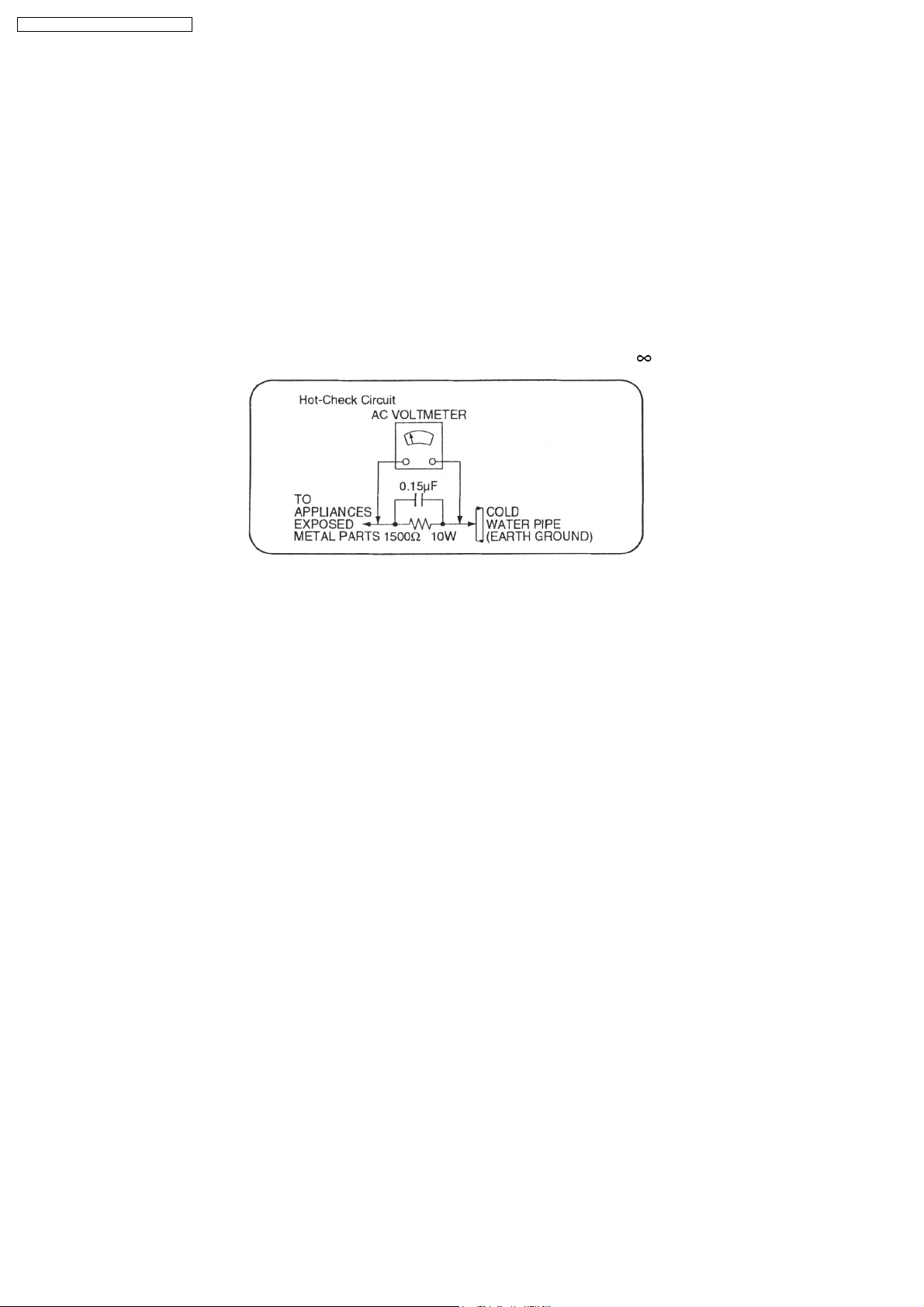
1.1.2. LEAKAGE CURRENT HOT CHECK (See Figure 1.)
1. Plug the AC cord directly into the AC outlet. Do not use an isolation transformer for this check.
2. Connect a 1.5kΩ, 10 watts resistor, in parallel with a 0.15µF capacitors, between each exposed metallic part on the set and a
good earth ground such as a water pipe, as shown in Figure 1.
3. Use an AC voltmeter, with 1000 ohms/volt or more sensitivity, to measure the potential across the resistor.
4. Check each exposed metallic part, and measure the voltage at each point.
5. Reverse the AC plug in the AC outlet and repeat each of the above measurements.
6. The potential at any point should not exceed 0.75 volts RMS. A leakage current tester (Simpson Model 229 or equivalent) may
be used to make the hot checks, leakage current must not exceed 1/2 milliamp. should the measurement is outside of the limits
specified, there is a possibility of a shock hazard, and the equipment should be repaired and re-checked before it is returned
to the customer.
4
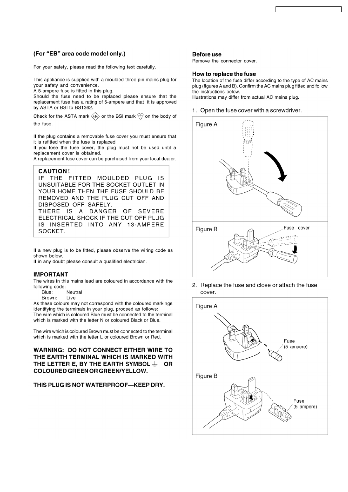
2 Caution for AC Mains Lead
SA-PM21E / SA-PM21EB / SA-PM21EG
5

SA-PM21E / SA-PM21EB / SA-PM21EG
3 Before Repair and Adjustment
Disconnect AC power, discharge Power Supply Capacitors C839 & C840 through a 10Ω, 1W resistor to ground.
DO NOT SHORT-CIRCUIT DIRECTLY (with a screwdriver blade, for instance), as this may destroy solid state devices.
After repairs are completed, restore power gradually using a variac, to avoid overcurrent.
· Current consumption at AC 230V, 50 Hz in NO SIGNAL mode (volume min) should be ~150 mA (E/EG).
· Current consumption at AC 230V-240V, 50 Hz in NO SIGNAL mode (volume min) should be ~150 mA (EB).
4 Protection Circuitry
The protection circuitry may have operated if either of the following conditions are noticed:
· No sound is heard when the power is turned on.
· Sound stops during a performance.
The function of this circuitry is to prevent circuitry damage if, for example, the positive and negative speaker connection wires are
"shorted", or if speaker systems with an impedance less than the indicated rated impedance of the amplifier are used.
If this occurs, follow the procedure outlines below:
1. Turn off the power.
2. Determine the cause of the problem and correct it.
3. Turn on the power once again after one minute.
Note:
When the protection circuitry functions, the unit will not operate unless the power is first turned off and then on again.
5 Handling the Lead-free Solder
5.1. About lead free solder (PbF)
Distinction of PbF P.C.B.:
P.C.B.s (manufactured) using lead free solder will have a PbF stamp on the P.C.B.
Caution:
· Pb free solder has a higher melting point than standard solder; Typically the melting point is 50 - 70°F (30 - 40°C) higher. Please
use a high temperature soldering iron. In case of soldering iron with temperature control, please set it to 700 ± 20°F (370 ±
10°C).
· Pb free solder will tend to splash when heated too high (about 1100°F/600°C).
· When soldering or unsoldering, please completely remove all of the solder on the pins or solder area, and be sure to heat the
soldering points with the Pb free solder until it melts enough.
6
SA-PM21E / SA-PM21EB / SA-PM21EG
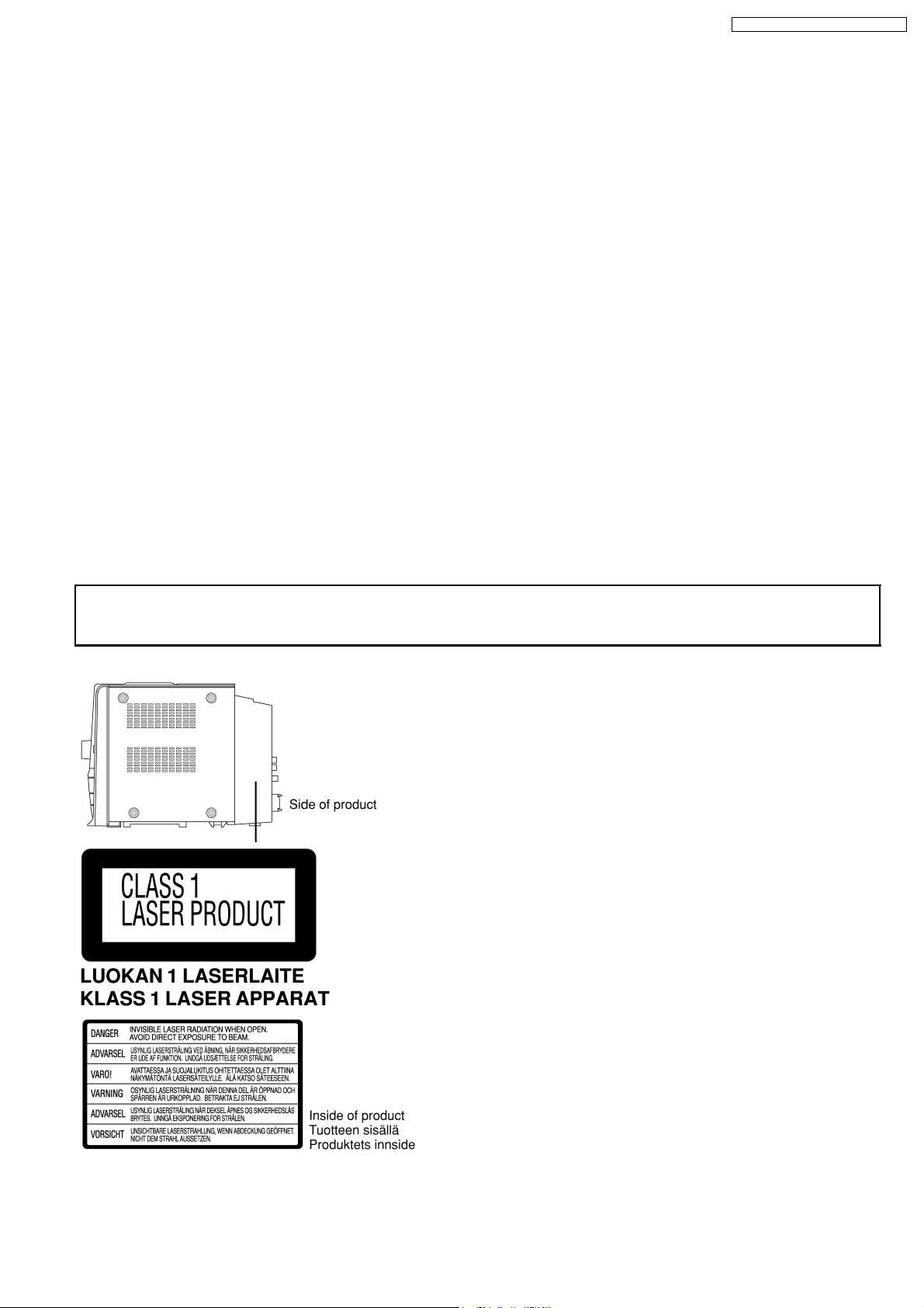
6 Precaution of Laser Diode
Caution :
This product utilizes a laser diode with the unit turned "ON", invisible laser radiation is emitted from the pick up lens.
Wavelength : 780 nm
Maximum output radiation power from pick up : 100 µW/VDE
Laser radiation from pick up unit is safety level, but be sure the followings:
1. Do not disassemble the optical pick up unit, since radiation from exposed laser diode is dangerous.
2. Do not adjust the variable resistor on the pick up unit. It was already adjusted.
3. Do not look at the focus lens using optical instruments.
4. Recommend not to look at pick up lens for a long time.
ACHTUNG :
Dieses Produkt enthält eine Laserdiode. Im eingeschalteten Zustand wird unsichtbare Laserstrahlung von der Lasereinheit
abgestrahlt.
Wellenlänge : 780nm
Maximale Strahlungsleistung der Lasereinheit :100µW/VD E
Die Strahlung an der Lasereinheit ist ungefährlich, wenn folgende Punkte beachtet werden:
1. Die Lasereinheit nicht zerlegen, da die Strahlung an der freigelegten Laserdiode gefährlich ist.
2. Den werkseitig justierten Einstellregler der Lasereinhit nicht verstellen.
3. Nicht mit optischen Instrumenten in die Fokussierlinse blicken.
4. Nicht über längere Zeit in die Fokussierlinse blicken.
ADVARSEL :
I dette a apparat anvendes laser.
CAUTION!
THIS PRODUCT UTILIZES A LASER.
USE OF CONTROLS OR ADJUSTMENTS OR PERFORMANCE OF PROCEDURES OTHER THAN THOSE SPECIFIED HEREIN MAY RESULT
IN HAZARDOUS RADIATION EXPOSURE.
Use of Caution Labels
n
7

SA-PM21E / SA-PM21EB / SA-PM21EG
7 Handling Precautions For Traverse Deck
The laser diode in the traverse deck (optical pickup) may break
down due to potential difference caused by static electricity of
clothes or human body.
So, be careful of electrostatic breakdown during repair of the
traverse deck (optical pickup).
l Handling of CD traverse deck (optical pickup)
1. Do not subject the traverse deck (optical pickup) to
static electricity as it is extremely sensitive to electrical
shock.
2. The short land between the No.4 (LD) and No.5 (GND)
pins on the flexible board (FFC) is shorted with a solder
build-up to prevent damage to the laser diode.
3. Take care not to apply excessive stress to the flexible
board (FFC board) (Fig 7.1).
4. Do not turn the variable resistor (laser power
adjustment). It has already been adjusted.
Fig 7.1
l Grounding for electrostatic breakdown prevention
1. Human body grounding (Fig 7.2)
Use the anti-static wrist strap to discharge the static
electricity from your body.
2. Work table grounding (Fig 7.2)
Put a conductive material (sheet) or steel sheet on the
area where the traverse deck (optical pickup) is placed,
and ground the sheet.
Caution :
The static electricity of your clothes will not be grounded
through the wrist strap. So, take care not to let your
clothes touch the traverse deck (optical pickup).
Fig 7.2
Caution when Replacing the Optical Pickup :
The traverse has a short point shorted with solder to protect
the laser diode against electrostatics breakdown. Be sure to
remove the solder from the short point before making
connections.
8
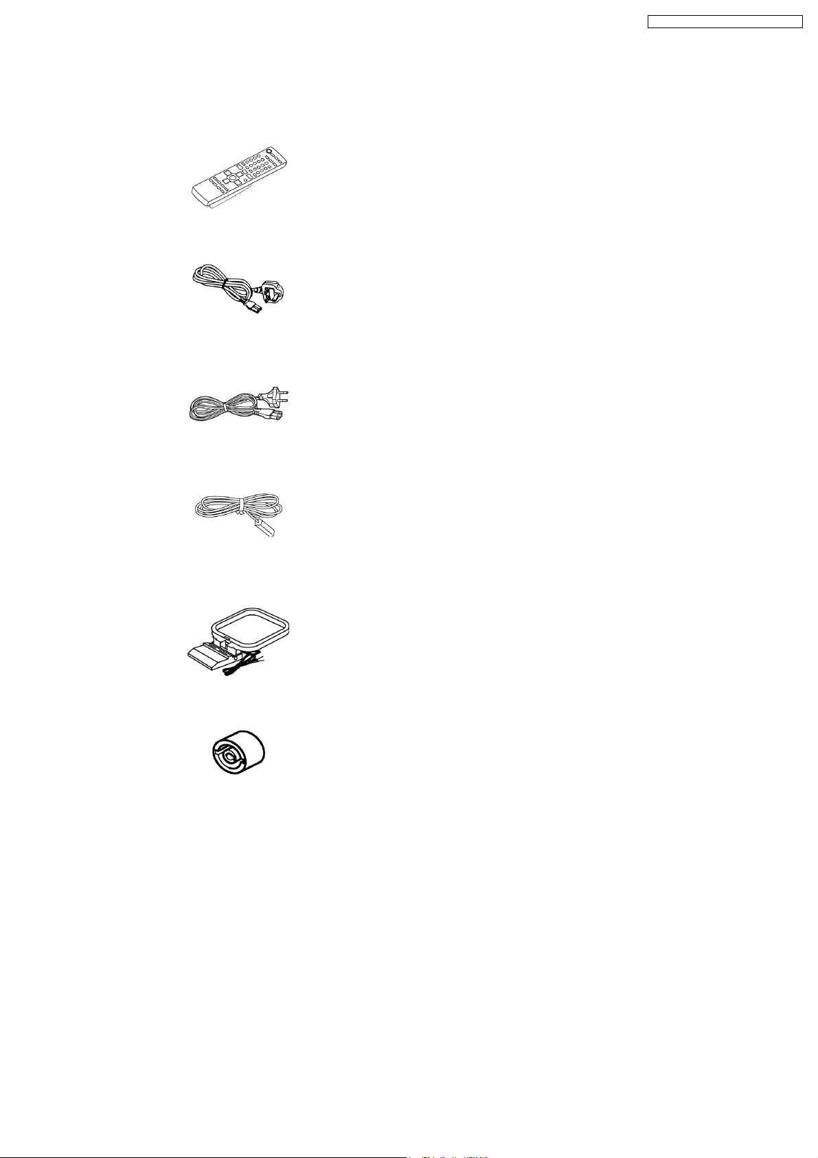
8 Accessories
Note : Refer to Packaging Materials & Accessories (Section 25.5) for the part number.
Remote control
AC cord (For EB
only)
SA-PM21E / SA-PM21EB / SA-PM21EG
AC cord (For E &
EG only)
FM indoor
antenna
AM loop antenna
Antenna
plug
adaptor
(For EB
only)
9

SA-PM21E / SA-PM21EB / SA-PM21EG
9 Operation Procedures
10
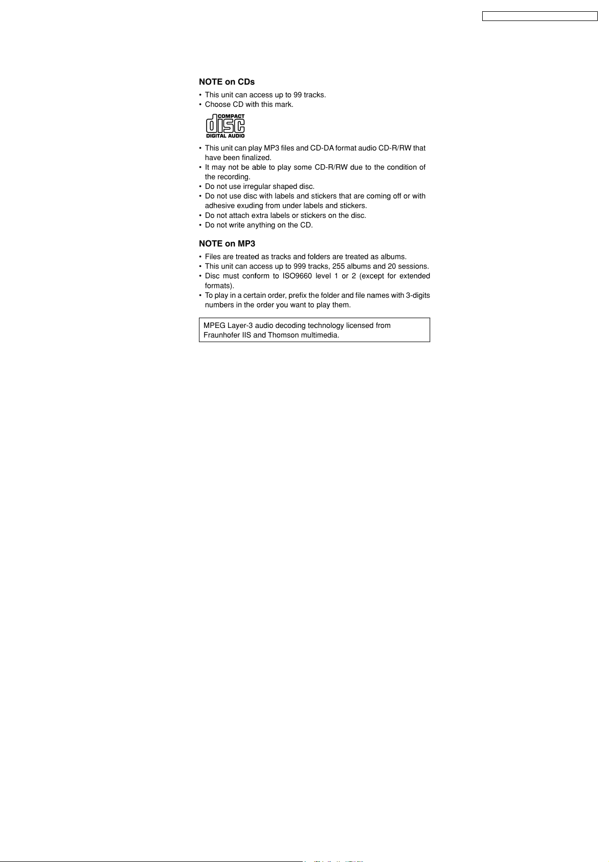
10 Information on CD & MP3
SA-PM21E / SA-PM21EB / SA-PM21EG
11
SA-PM21E / SA-PM21EB / SA-PM21EG
11 Assembling and Disassembling
“ATTENTION SERVICER”
Some chassis components may be have sharp edges. Be careful when disassembling and servicing.
1. This section describes procedures for checking the operation of the major printed circuit boards and replacing the main
components.
2. For reassembly after operation checks or replacement, reverse the respective procedures.
Special reassembly procedures are described only when required.
3. Select items from the following index when checks or replacement are required.
Warning:
This product uses a laser diode. Refer to “Precaution of Laser Diode”.
ACHTUNG:
Die Lasereinheit nicht zerlegen.
Die Lasereinheit darf nur gegen eine vom Hertsteller spezifizierte Einheit ausgetauscht werden.
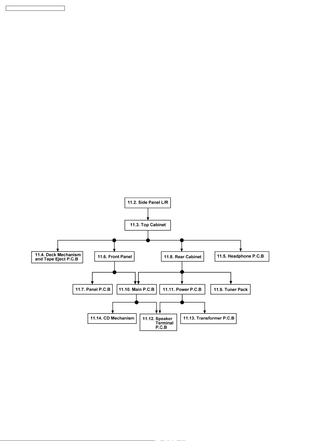
11.1. Disassembly flow chart
The following chart is the procedure for disassembling the casing and inside parts for internal inspection when carrying out the
servicing.
To assemble the unit, reverse the steps shown in the chart below.
12
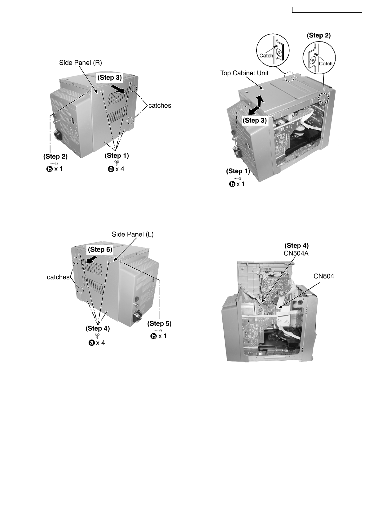
11.2. Disassembly of Side Panel L &
R
Step 1 : Remove 4 screws.
Step 2 : Remove 1 screw.
Step 3 : Remove the side panel (R) as arrow shown (Be careful
of the catches).
SA-PM21E / SA-PM21EB / SA-PM21EG
Step 1 : Remove 1 screw.
Step 2 : Release catches at both ends.
Step 3 : Lift up the top cabinet unit, push backward as arrow
shown and flip top cabinet unit sideway.
Step 4 : Remove 4 screws.
Step 5 : Remove 1 screw.
Step 6 : Remove the side panel (L) as arrow shown (Be careful
of the catches).
11.3. Disassembly of Top Cabinet
Unit
· Follow the (Step 1) - (Step 6) of Item 11.2.
Step 4 : Detach the connectors CN504A and FFC CN804.
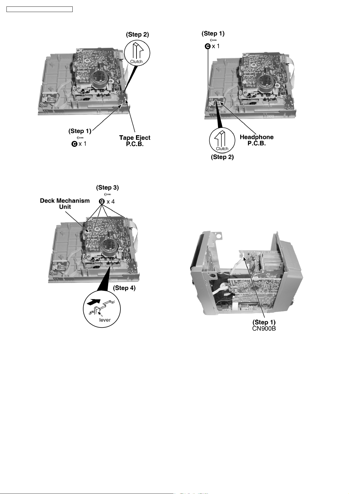
11.4. Disassembly of Deck
Mechanism and Tape Eject
P.C.B
· Follow the (Step 1) - (Step 6) of Item 11.2.
· Follow the (Step 1) - (Step 4) of Item 11.3.
13
SA-PM21E / SA-PM21EB / SA-PM21EG
Step 1 : Remove 1 screw.
Step 2 : Release the clutch.
Step 1 : Remove 1 screw.
Step 2 : Release the clutch.
Step 3 : Remove 4 screws.
Step 4 : Push the lever as arrow shown to open the cassette lid
and remove the deck mechanism unit.
11.6. Disassembly of Front Panel
Assembly
· Follow the (Step 1) - (Step 6) of Item 11.2.
· Follow the (Step 1) - (Step 4) of Item 11.3.
Step 1 : Detach the connector CN900B .
11.5. Disassembly of Headphone
P.C.B
· Follow the (Step 1) - (Step 6) of Item 11.2.
· Follow the (Step 1) - (Step 4) of Item 11.3.
14
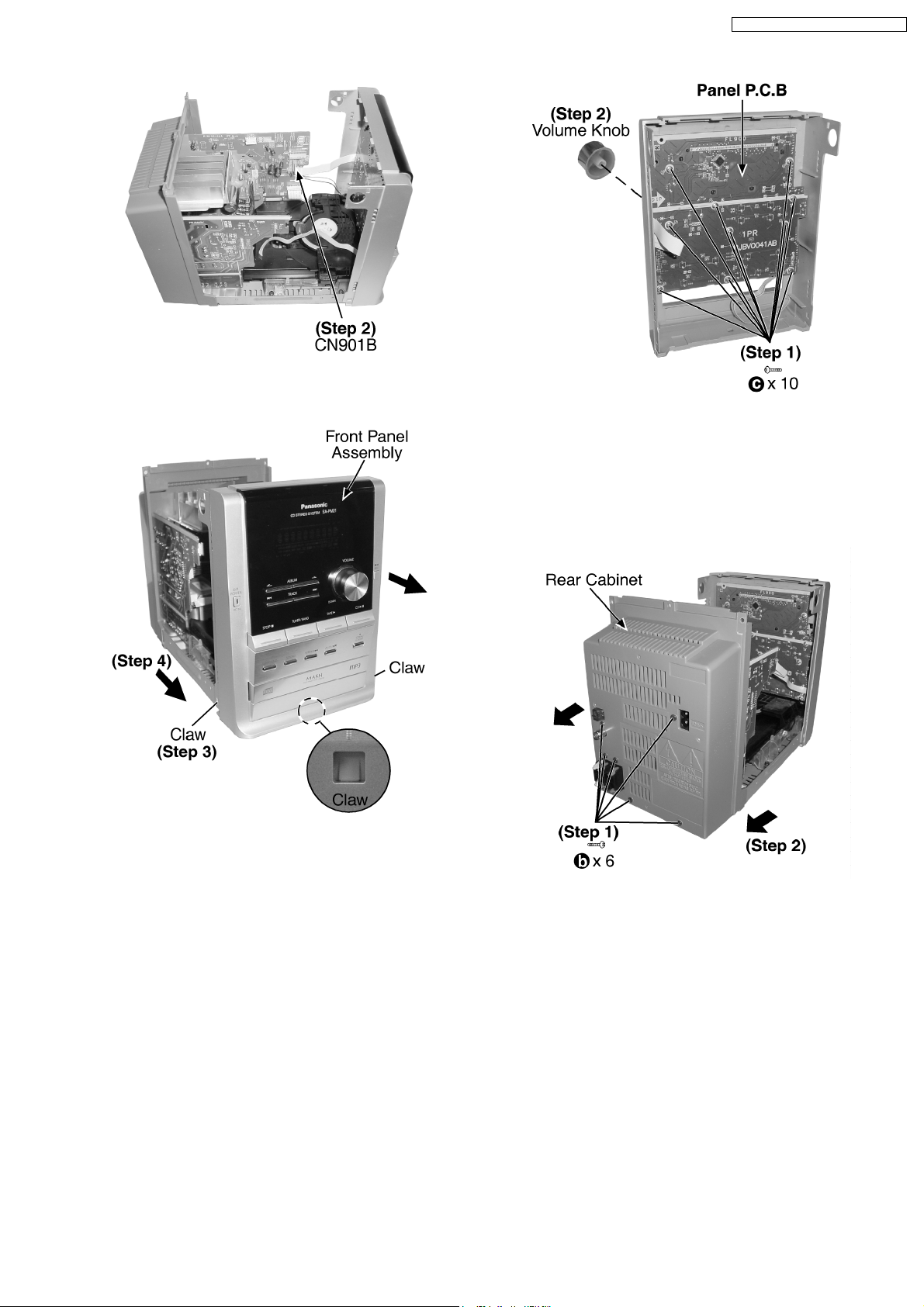
Step 2 : Detach the FFC CN901B.
SA-PM21E / SA-PM21EB / SA-PM21EG
Step 1 : Remove 10 screws.
Step 2 : Remove the volume knob.
Step 3 : Release 3 Claws.
Step 4 : Remove the front panel assembly as arrow shown.
11.7. Disassembly of Panel P.C.B
· Follow the (Step 1) - (Step 6) of Item 11.2.
· Follow the (Step 1) - (Step 4) of Item 11.3.
· Follow the (Step 1) - (Step 4) of Item 11.6.
11.8. Disassembly of Rear Cabinet
· Follow the (Step 1) - (Step 6) of Item 11.2.
· Follow the (Step 1) - (Step 4) of Item 11.3.
Step 1 : Remove 6 screws.
Step 2 : Remove the rear cabinet as arrow shown.
11.9. Disassembly of Tuner Pack
· Follow the (Step 1) - (Step 6) of Item 11.2.
· Follow the (Step 1) - (Step 4) of Item 11.3.
· Follow the (Step 1) - (Step 2) of Item 11.8.
15
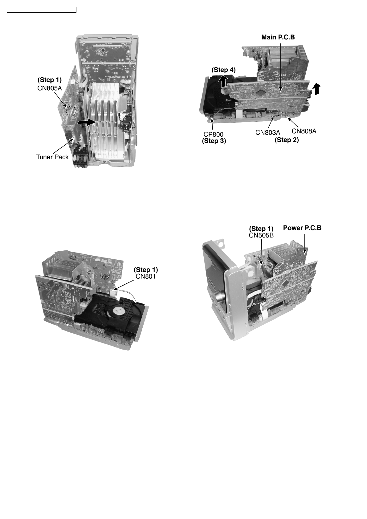
SA-PM21E / SA-PM21EB / SA-PM21EG
Step 1 : Detach the connector CN805A and remove the tuner
pack as arrow shown.
11.10. Disassembly of Main P.C.B
· Follow the (Step 1) - (Step 6) of Item 11.2.
· Follow the (Step 1) - (Step 4) of Item 11.3.
· Follow the (Step 1) - (Step 4) of Item 11.6.
· Follow the (Step 1) - (Step 2) of Item 11.8.
Step 2 : Detach the connector CN803A, CN808A.
Step 3 : Detach the connector CP800.
Step 4 : Remove the Main P.C.B as arrow shown.
11.11. Disassembly of Power P.C.B
· Follow the (Step 1) - (Step 6) of Item 11.2.
· Follow the (Step 1) - (Step 4) of Item 11.3.
· Follow the (Step 1) - (Step 2) of Item 11.8.
Step 1 : Detach the FFC CN801.
Step 1 : Detach the connector CN505B.
16
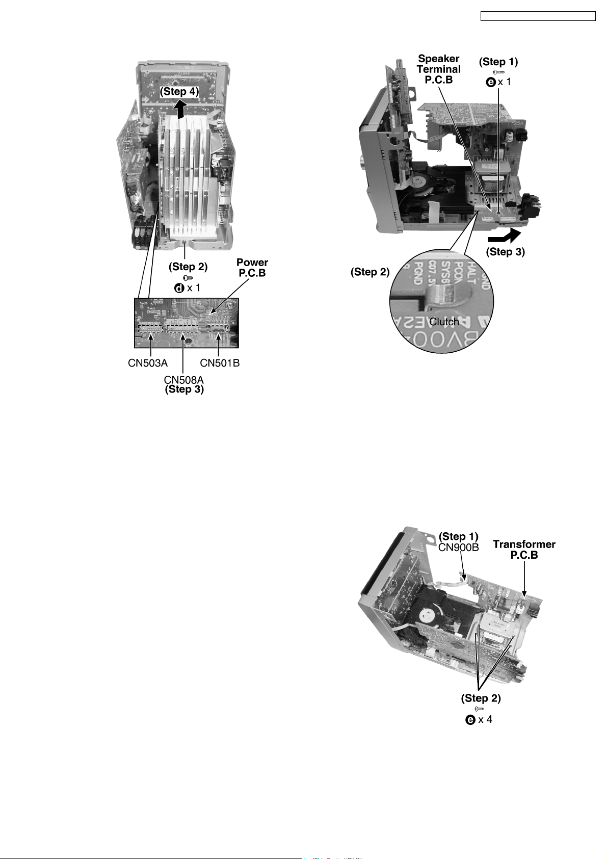
SA-PM21E / SA-PM21EB / SA-PM21EG
Step 2 : Remove 1 screw.
Step 3 : Detach the connector CN503A, CN508A, CN501B.
Step 4 : Remove the Power P.C.B as arrow shown.
11.12. Disassembly of Speaker
Terminal P.C.B
· Follow the (Step 1) - (Step 6) of Item 11.2.
· Follow the (Step 1) - (Step 4) of Item 11.3.
· Follow the (Step 1) - (Step 2) of Item 11.8.
· Follow the (Step 1) - (Step 2) of Item 11.10.
· Follow the (Step 2) - (Step 4) of Item 11.11.
Step 1 : Remove 1 screw.
Step 2 : Release the clutch.
Step 3 : Remove the Speaker Terminal P.C.B as arrow shown.
11.13. Disassembly of Transformer
P.C.B
· Follow the (Step 1) - (Step 6) of Item 11.2.
· Follow the (Step 1) - (Step 4) of Item 11.3.
· Follow the (Step 1) - (Step 2) of Item 11.8.
· Follow the (Step 1) - (Step 4) of Item 11.11.
Step 1 : Detach the connector CN900B.
Step 2 : Remove 4 screws.
17

SA-PM21E / SA-PM21EB / SA-PM21EG
11.14. Disassembly of CD
Mechanism
· Follow the (Step 1) - (Step 6) of Item 11.2.
· Follow the (Step 1) - (Step 4) of Item 11.3.
· Follow the (Step 1) - (Step 4) of Item 11.6.
· Follow the (Step 1) - (Step 2) of Item 11.8 .
· Follow the (Step 1) - (Step 4) of Item 11.10.
Step 1 : Remove 4 screws.
Step 2 : Remove the Main P.C.B Support.
18
SA-PM21E / SA-PM21EB / SA-PM21EG
11.15. Checking Procedure for Each
Major P.C.B.
11.15.1. Replacement of the Power
Amplifier IC
· Replacement of the Power Amplifier IC
· Follow the (Step 1) - (Step 6) of Item 11.2.
· Follow the (Step 1) - (Step 4) of Item 11.3.
· Follow the (Step 1) - (Step 2) of Item 11.8.
· Follow the (Step 1) - (Step 4) of Item 11.11.
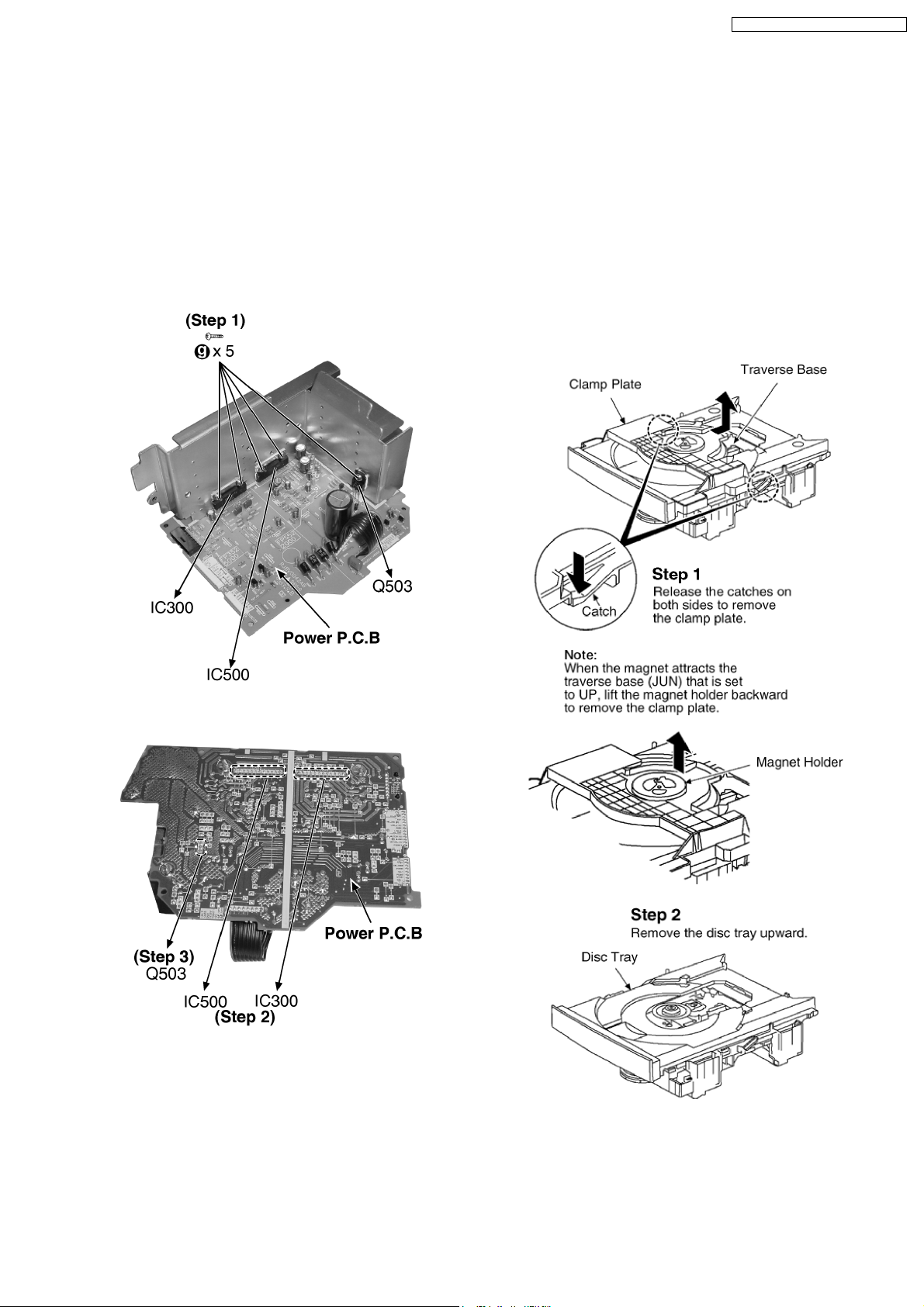
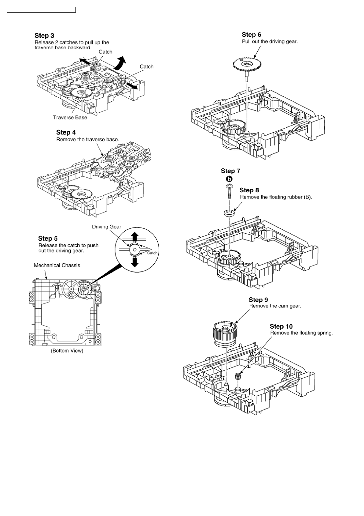
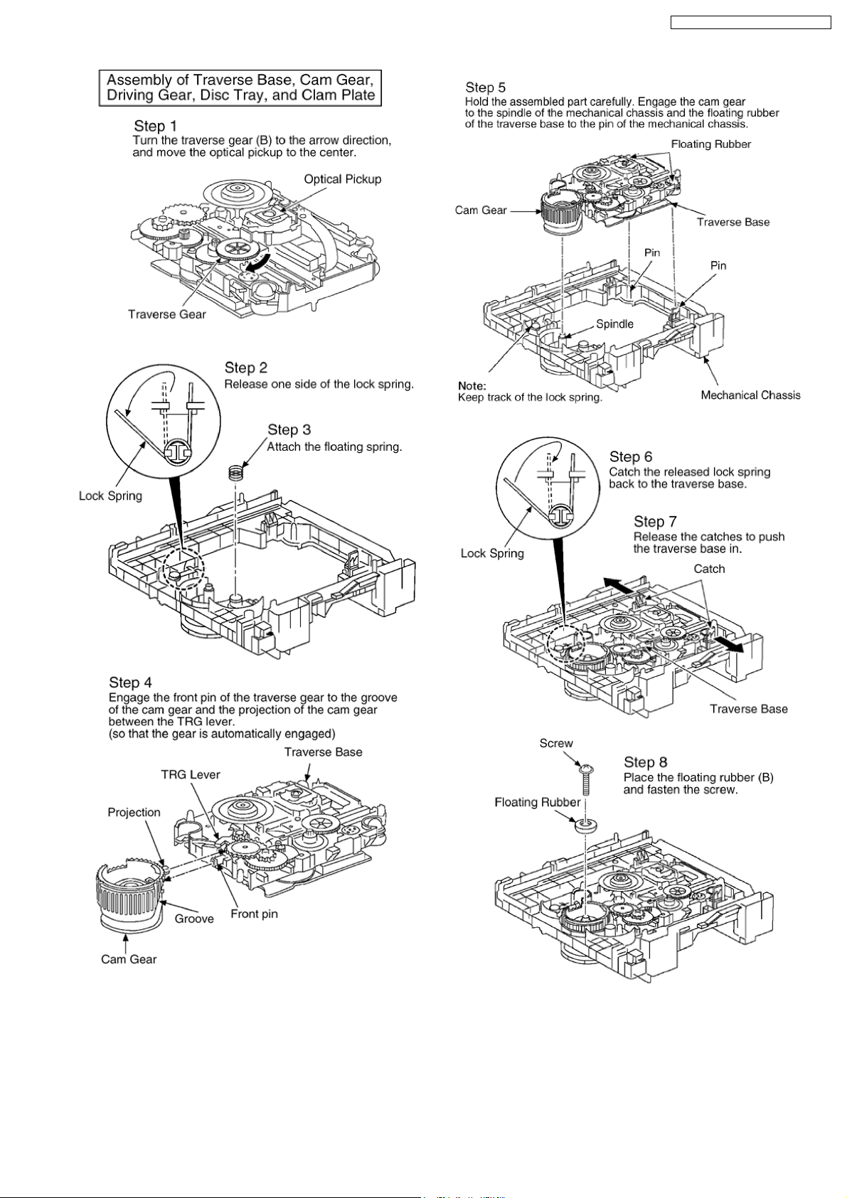
11.16. Procedures of Replacing
Traverse Base (Unit), Driving
Gear, and Cam Gear (CD
Mechanism Unit)
11.16.1. Disassembly of the Disc Tray.
· Follow the (Step 1) - (Step 6) of Item 11.2.
· Follow the (Step 1) - (Step 4) of Item 11.3.
· Follow the (Step 1) - (Step 4) of Item 11.6.
· Follow the (Step 1) - (Step 2) of Item 11.8 .
· Follow the (Step 1) - (Step 4) of Item 11.10.
· Follow the (Step 1) - (Step 2) of Item 11.14.
Step 1 Remove 5 screws.
Step 2 Unsolder the terminals of Power Amp IC (IC300, IC500)
and replace the component.
Step 3 Unsolder the terminals of Transistor (Q503) and replace
the component.
19
SA-PM21E / SA-PM21EB / SA-PM21EG
20
SA-PM21E / SA-PM21EB / SA-PM21EG
21
SA-PM21E / SA-PM21EB / SA-PM21EG
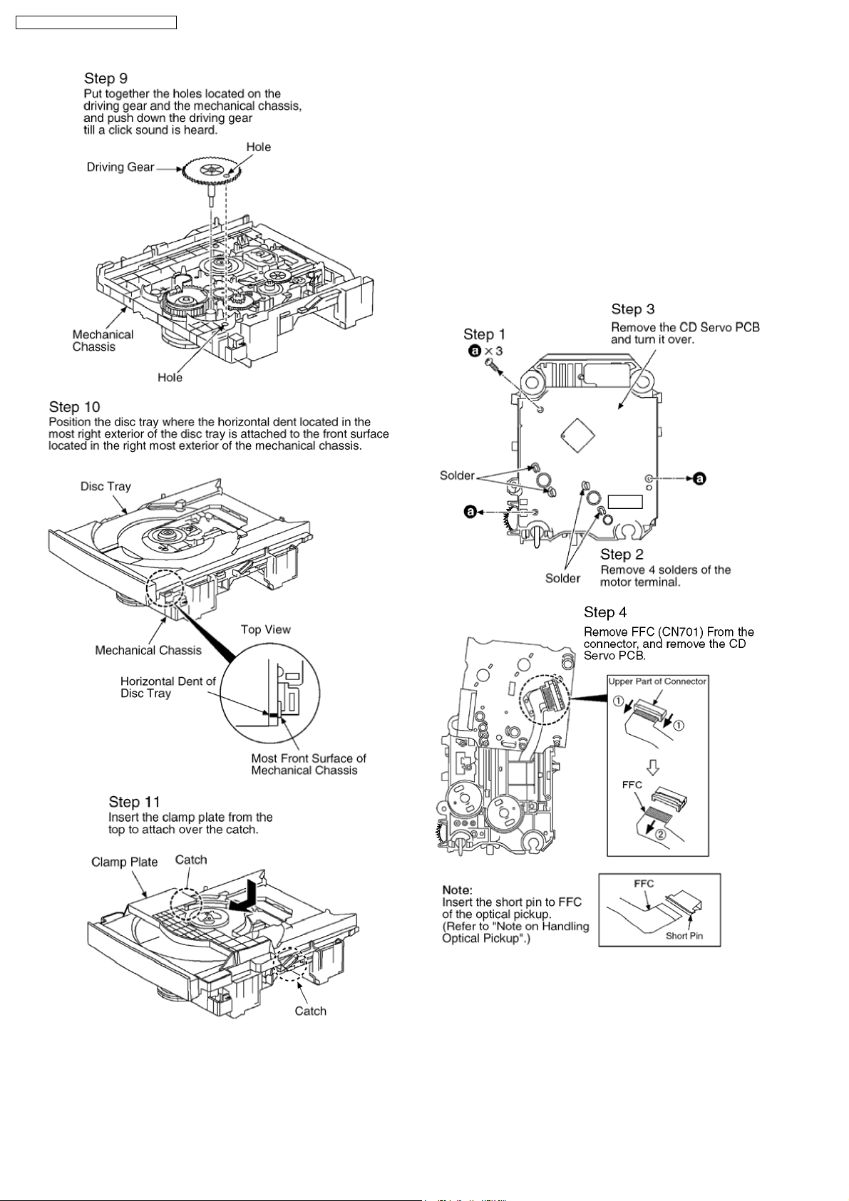
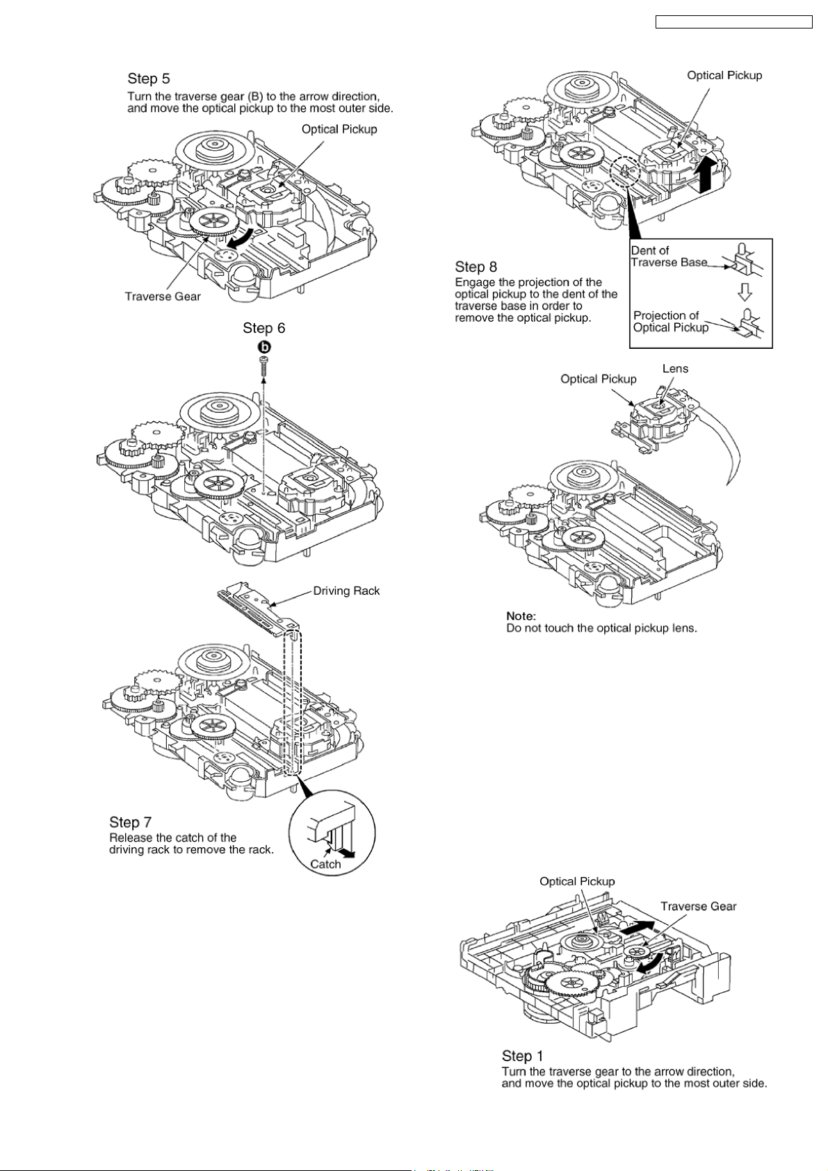
11.17. Procedures for Replacing
Optical Pickup (CD Mechanism
Unit)
· Follow the (Step 1) - (Step 6) of Item 11.2.
· Follow the (Step 1) - (Step 4) of Item 11.3.
· Follow the (Step 1) - (Step 4) of Item 11.6.
· Follow the (Step 1) - (Step 2) of Item 11.8 .
· Follow the (Step 1) - (Step 4) of Item 11.10.
· Follow the (Step 1) - (Step 2) of Item 11.14.
· Follow the (Step 1) - (Step 4) of Item 11.16.1.
22
SA-PM21E / SA-PM21EB / SA-PM21EG
11.18. Procedures for Replacement
Traverse Gear A and Traverse
Gear B (CD Mechanism Unit)
· Follow the (Step 1) - (Step 6) of Item 11.2.
· Follow the (Step 1) - (Step 4) of Item 11.3.
· Follow the (Step 1) - (Step 4) of Item 11.6.
· Follow the (Step 1) - (Step 2) of Item 11.8 .
· Follow the (Step 1) - (Step 4) of Item 11.10.
· Follow the (Step 1) - (Step 2) of Item 11.14.
· Follow the (Step 1) - (Step 2) of Item 11.16.1.
23

SA-PM21E / SA-PM21EB / SA-PM21EG
11.19. Procedure for Replacing
Cassette Holder
· Follow the (Step 1) - (Step 6) of Item 11.2.
· Follow the (Step 1) - (Step 4) of Item 11.3.
· Follow the (Step 1) - (Step 4) of Item 11.4.
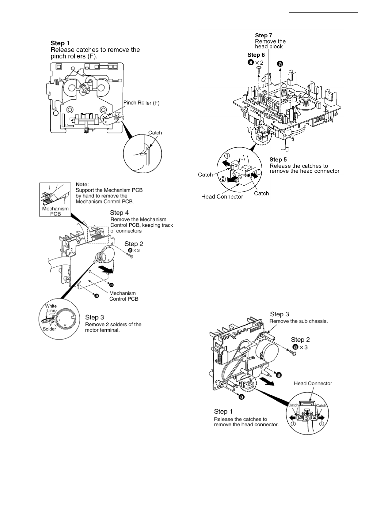
11.20. Procedure for Replacing Pinch
Roller and Head Block
(Cassette Mechanism Unit)
· Follow the (Step 1) - (Step 6) of Item 11.2.
· Follow the (Step 1) - (Step 4) of Item 11.3.
24
· Follow the (Step 1) - (Step 4) of Item 11.4.
SA-PM21E / SA-PM21EB / SA-PM21EG
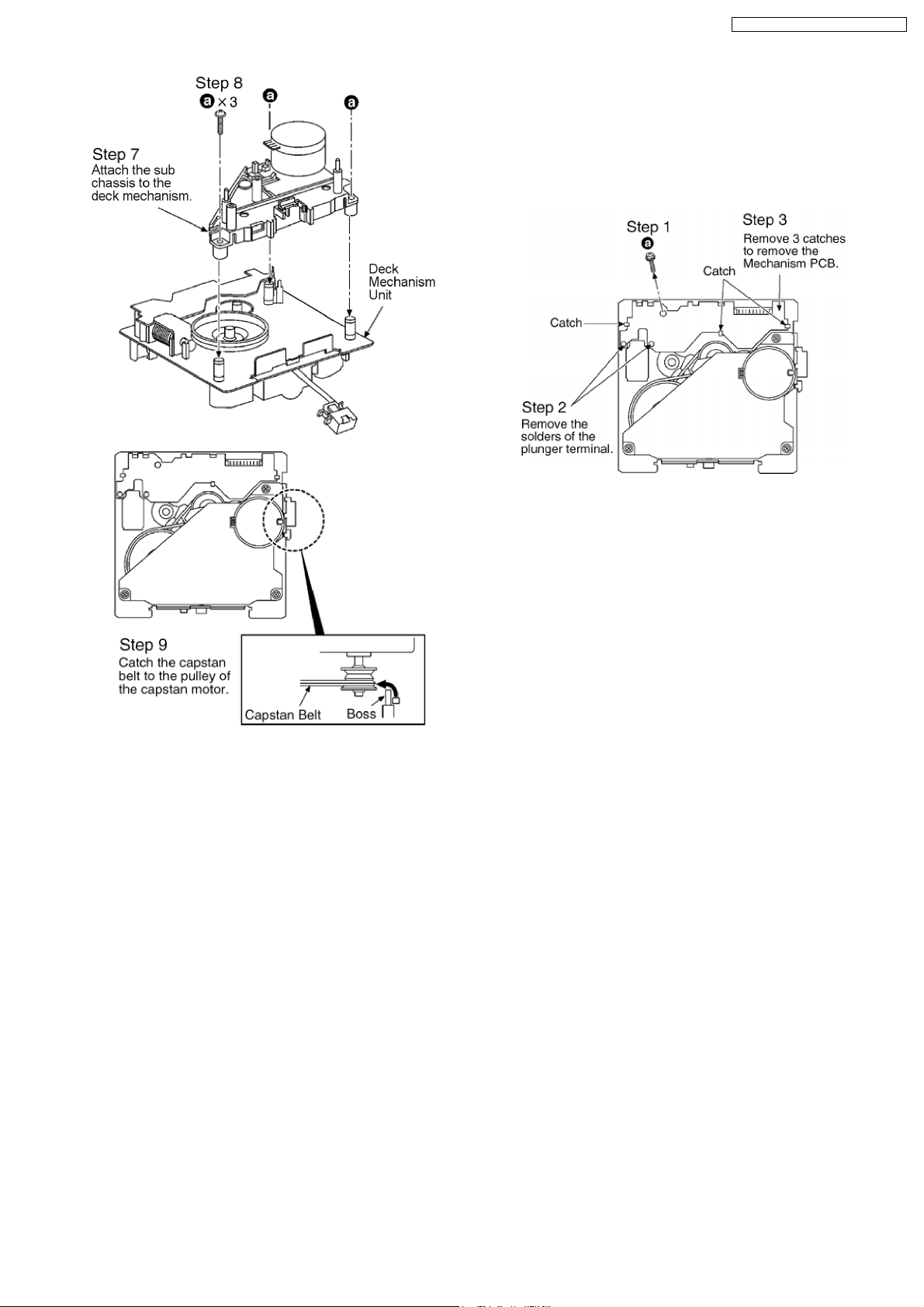
11.21. Procedure for Replacing
Motor, Capstan Belt A,
Capstan Belt B, and Winding
Belt (Cassette Mechanism
Unit)
· Follow the (Step 1) - (Step 6) of Item 11.2.
· Follow the (Step 1) - (Step 4) of Item 11.3.
· Follow the (Step 1) - (Step 4) of Item 11.4.
· Follow the (Step 1) - (Step 4) of Item 11.20.
25

SA-PM21E / SA-PM21EB / SA-PM21EG
26
SA-PM21E / SA-PM21EB / SA-PM21EG
11.22. Procedure for Replacing Parts
on Mechanism PCB
· Follow the (Step 1) - (Step 6) of Item 11.2.
· Follow the (Step 1) - (Step 4) of Item 11.3.
· Follow the (Step 1) - (Step 4) of Item 11.4.
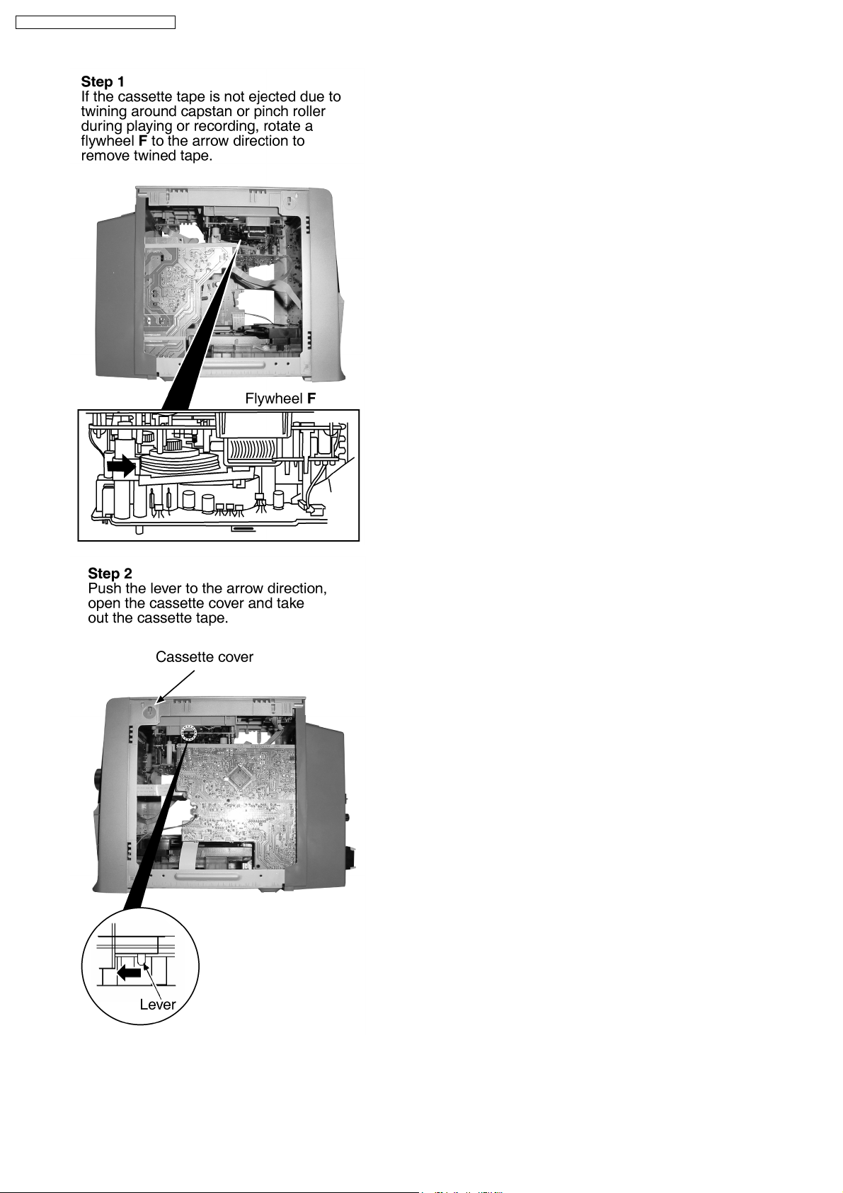
11.23. Handling of cassette tape jam
· Follow the (Step 1) - (Step 6) of Item 11.2.
27
SA-PM21E / SA-PM21EB / SA-PM21EG
28
 Loading...