

ORDER NO. MD0303075C2
CD Stereo System
SA-PM10E / SA-PM10EB / SA-PM10EG
Colour
(S)... Silver Type
TAPE SECTION
SPECIFICATIONS
AR2 MECHANISM SERIES
Specification
1

Amplifier Section
RMS Power output
THD 10%, both channels driven 15 W per channel (6 )
Output impedance
Headphone 16-32
FM Tuner Section
Frequency range 87.50-108.00 MHz
(50 kHz step)
Sensitivity
S/N 26 dB
Antenna terminals 75 unbalanced
AM Tuner Section
Frequency range 522-1629 KHz (9 kHz steps)
520-1630 KHz (10 kHz steps)
Sensitivity
S/N 20 dB (at 999 kHz)
Cassette Deck Section
Track system 4 track, 2 channel
Heads
Record/playback Solid permalloy head
Erasure AC erase head
Motor DC servo motor
Recording system AC bias 100 kHz
Erasing system AC erase 100 kHz
Tape speed 4.8 cm/s
Overall frequency response (+3 to -6 dB at DECK OUT)
NORMAL (TYPE I) 35 Hz - 14 kHz
S/N 50 dB (A weighted)
Wow and flutter 0.15% (WRMS)
Fast forward and rewind time Approx. 120 seconds with C-60
CD Section
Sampling frequency 44.1 kHz
Decoding 16 bit linear
Beam source Semiconductor laser
Wavelength 780 nm
Number of channels 2 channels stereo
Wow and flutter Below measurable limit
Digital filter 8 fs
D/A converter MASH (1 bit DAC)
General
Power supply AC 220-230V, 50Hz
Power consumption 48 W
Power consumption (Standby
mode)
Dimensions (W x H x D) 165 x 228 x 313 mm
Mass 3.9 kg
2.0 V (IHF)
1.5 V
560 V/m
cassette tape
0.8 W
2
Notes :
1. Specifications are subject to change without notices. Mass
and dimensions are approximate.
2. Total harmonic distortion is measured by the digital spectrum
analyzer.
System : SC-PM10 (E)
System : SC-PM10 (EB)
System : SC-PM10 (EG)
Music center: SA-PM10 (E)
Speaker: SB-PM10 (P)
Music center: SA-PM10 (EB)
Speaker: SB-PM10 (P)
Music center: SA-PM10 (EG)
Speaker: SB-PM10 (EG)
2003 Matsushita Electronics (S) Pte. Ltd. All rights reserved.
Unauthorized copying and distribution is a violation of law.
1. Before Repair and Adjustment
Disconnect AC power, discharge Power Supply Capacitors C501, C604, C608, C906 & C908
through a 10 , 5W resistor to ground.
DO NOT SHORT-CIRCUIT DIRECTLY (with a screwdriver blade, for instance), as this may
destroy solid state devices.
After repairs are completed, restore power gradually using a variac, to avoid overcurrent.
- Current consumption at AC 230V, 50 Hz in NO SIGNAL mode
should be ~150 mA.
2. Protection Circuitry
The protection circuitry may have operated if either of the following conditions are noticed:
- No sound is heard when the power is turned on.
- Sound stops during a performance.
The function of this circuitry is to prevent circuitry damage if, for example, the positive and
negative speaker connection wires are "shorted", or if speaker systems with an impedance less
than the indicated rated impedance of the amplifier are used.
If this occurs, follow the procedure outlines below:
1. Turn off the power.
2. Determine the cause of the problem and correct it.
3. Turn on the power once again after one minute.
Note:
When the protection circuitry functions, the unit will not operate unless the power is first turned
3
off and then on again.
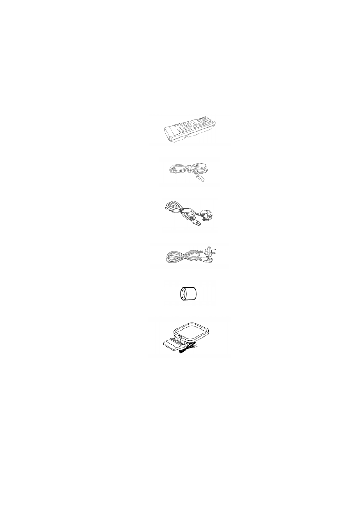
3. Accessories
Note : Refer to Packing Materials & Accessories for part number.
Remote Control Transmitter
FM indoor antenna
AC mains lead (For EB only)
AC mains lead (For E & EG only)
Antenna plug adapter (For EB only)
AM Loop antenna
4. Operation Procedures
4
5. Handling the Lead-free Solder
5.1. About lead free solder (PbF)
Distinction of PbF P.C.B.:
P.C.B.s (manufactured) using lead free solder will have a PbF stamp on the P.C.B.
5

Caution:
- Pb free solder has a higher melting point than standard solder;
Typically the melting point is 50 - 70°F (30 - 40°C) higher. Please
use a high temperature soldering iron. In case of soldering iron
with temperature control, please set it to 700 ± 20°F (370 ± 10°C).
- Pb free solder will tend to splash when heated too high (about
1100°F/600°C).
- When soldering or unsoldering, please completely remove all of
the solder on the pins or solder area, and be sure to heat the
soldering points with the Pb free solder until it melts enough.
6. Handling Precautions For Traverse Deck
The laser diode in the traverse deck (optical pickup) may break down due to potential difference
caused by static electricity of clothes or human body.
So, be careful of electrostatic breakdown during repair of the traverse deck (optical pickup).
Handling of CD traverse deck (optical pickup)
1. Do not subject the traverse deck (optical pickup) to static
electricity as it is extremely sensitive to electrical shock.
2. The short land between the No.4 (LD) and No.5 (GND) pins on the
flexible board (FFC) is shorted with a solder build-up to prevent
damage to the laser diode.
3. Take care not to apply excessive stress to the flexible board (FPC
board).
4. Do not turn the variable resistor (laser power adjustment). It has
already been adjusted.
6
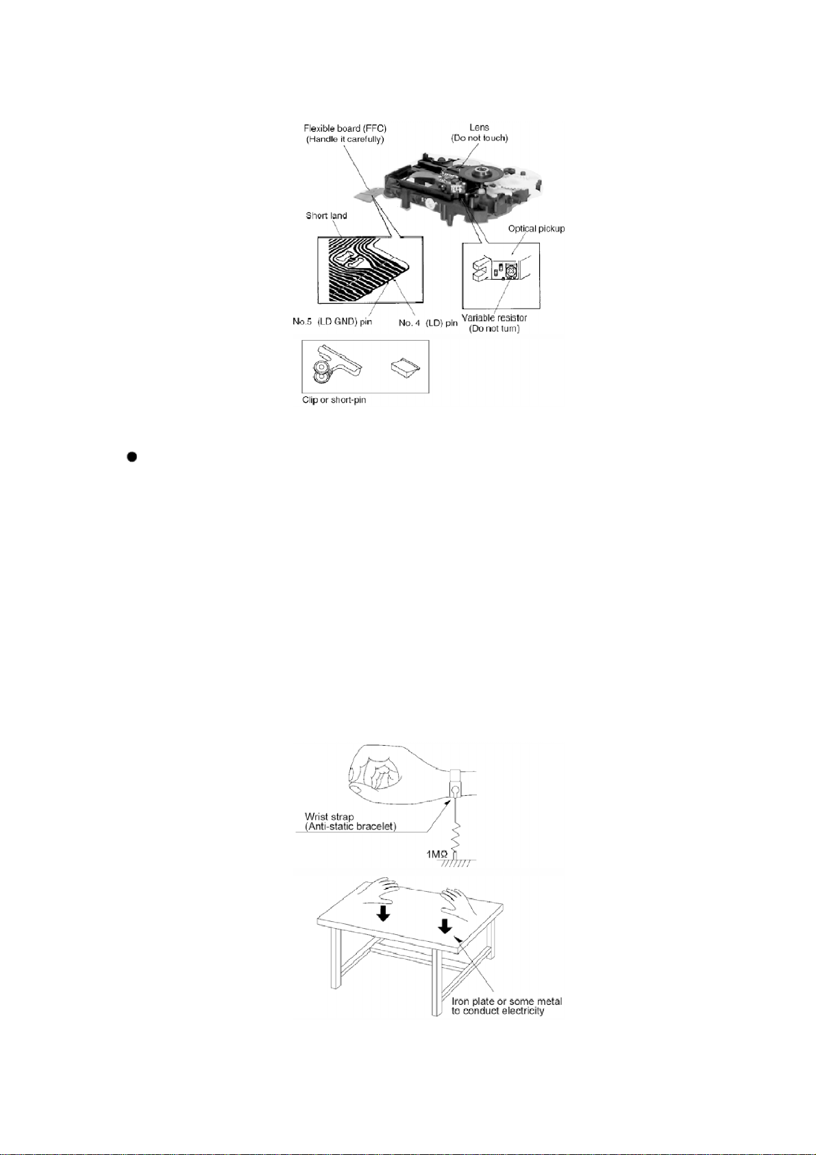
Grounding for electrostatic breakdown prevention
1. Human body grounding
Use the anti-static wrist strap to discharge the static electricity
from your body.
2. Work table grounding
Put a conductive material (sheet) or steel sheet on the area where
the traverse deck (optical pickup) is placed, and ground the sheet.
Caution :
The static electricity of your clothes will not be grounded through
the wrist strap. So, take care not to let your clothes touch the
traverse deck (optical pickup).
7
Caution when Replacing the Optical Pickup :
The traverse has a short point shorted with solder to protect the
laser diode against electrostatics breakdown. Be sure to remove
the solder from the short point before making connections.
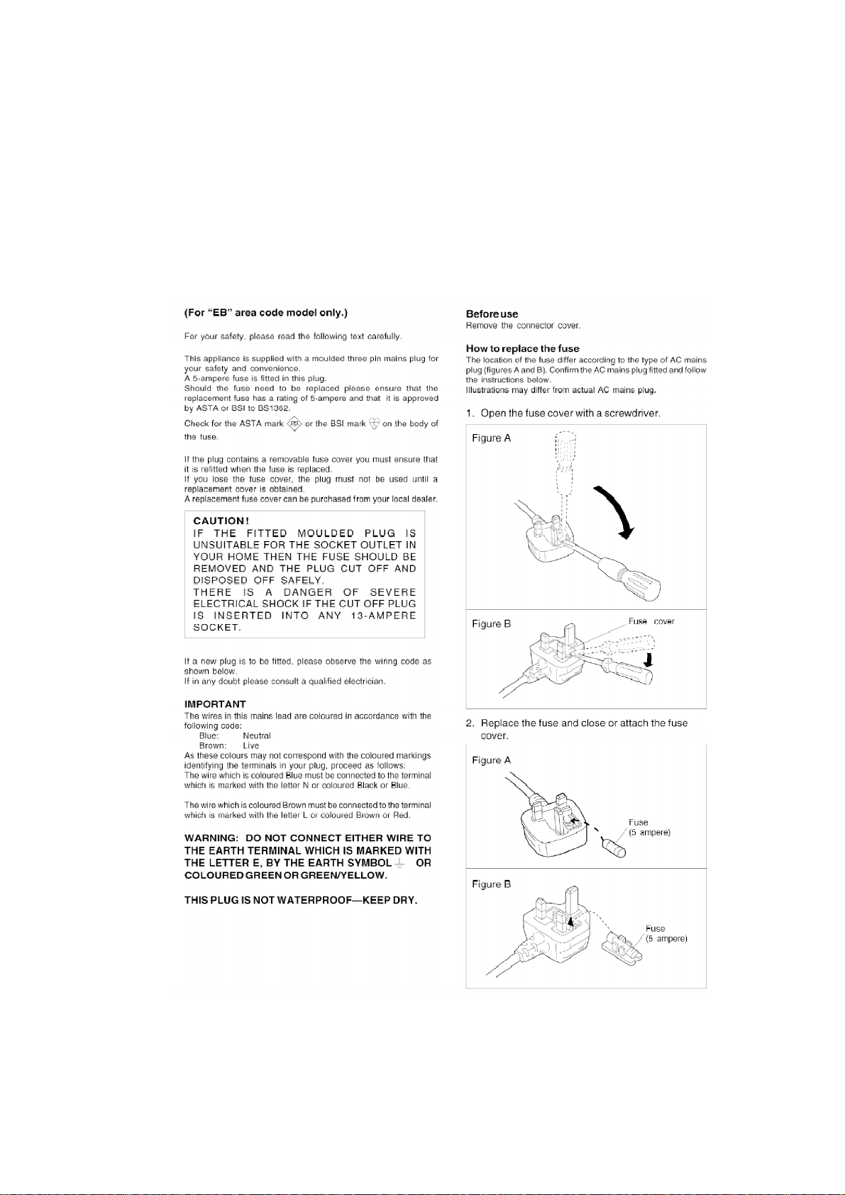
7. Caution for AC Mains Lead
8. Operation Check and Main Component
Replacement Procedures
8

“ATTENTION SERVICER”
Some chassis components may have sharp edges. Be careful when
disassembling and servicing.
1. This section describes procedures for checking the operation of
the major printed circuit boards and replacing the main
components.
2. For reassembly after operation checks or replacement, reverse
the respective procedures.Special reassembly procedures are
described only when required.
3. Select items from the following index when checks or
replacement are required.
4. Refer the Parts No. on the page of "Main Component Replacement
Procedures", if necessary.
Contents
- Checking Procedure for each major P.C.B.
- Checking of the Main P.C.B. & Transformer P.C.B.
- Checking for the Deck P.C.B. , Headphone P.C.B. and Tape Eject
P.C.B.
- Checking for the Panel P.C.B. and Power P.C.B. and Speaker
Terminal P.C.B.
- Checking for the CD Servo P.C.B.
- Disassembly and Assembly of the Disc Tray and CD Traverse Unit
- Disassembly of the Disc Tray
- Disassembly of the CD Traverse Unit
- Main Component Replacement Procedure
- Replacement of the CD Servo P.C.B. and Optical Pick-up Unit
- Procedure for Replacing Cassette Holder
- Procedure for Replacing Pinch Roller and Head Block (Cassette
Mechanism Unit)
- Procedure for Replacing Motor, Capstan Belt A, Capstan Belt B
and Winding Belt (Cassette Mechanism Unit)
- Procedure for Replacing parts on Mechanism P.C.B.
Warning :-
This product uses a laser diode. Refer to caution statement
9
“Precaution of Laser Diode”.
ACHTUNG :-
- Die Lasereinheit nicht zerlegen.
- Die Lasereinheit darf nur gegen eine vom Hertsteller spezifizierte
Einheit ausgetauscht werden.
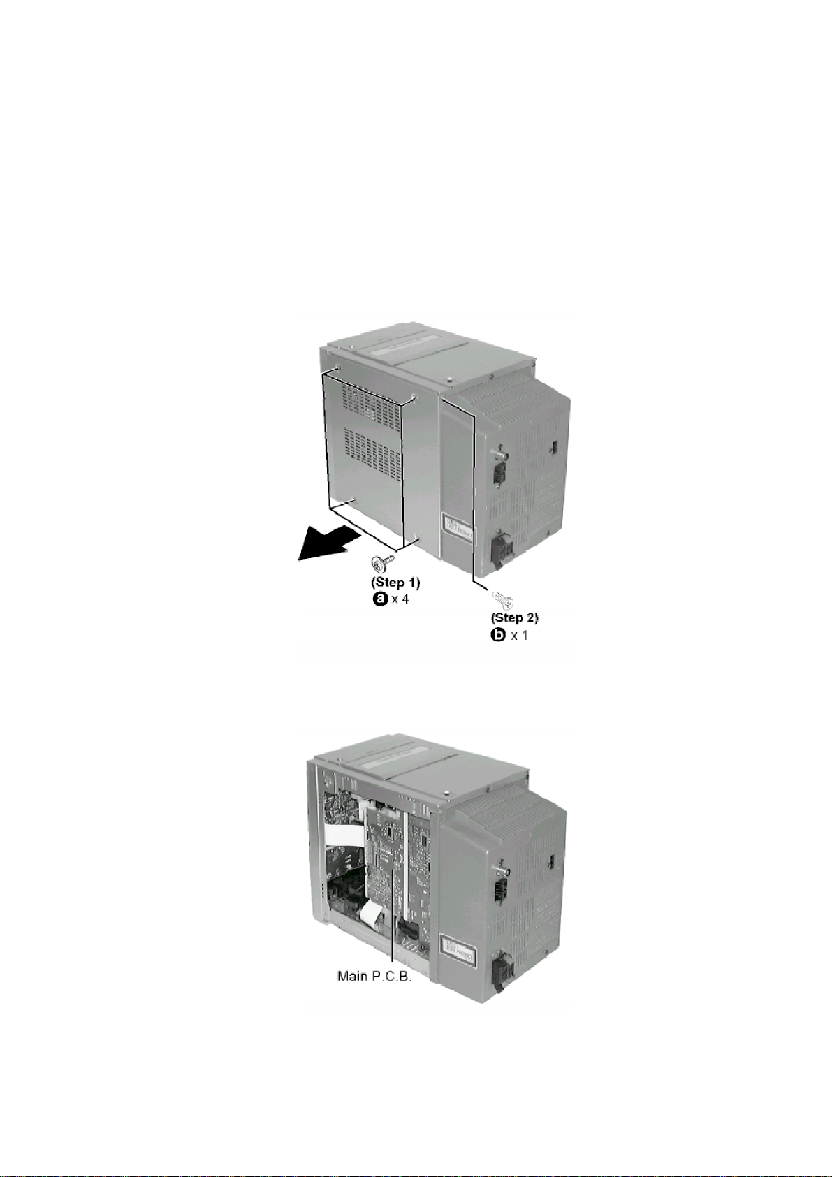
8.1. Checking Procedure for Each Major P.C.B.
8.1.1. Checking for Main & Transformer P.C.B.
Step 1 Remove all the screws.
Step 2 Remove side panel.
- Checking for Main P.C.B.
10
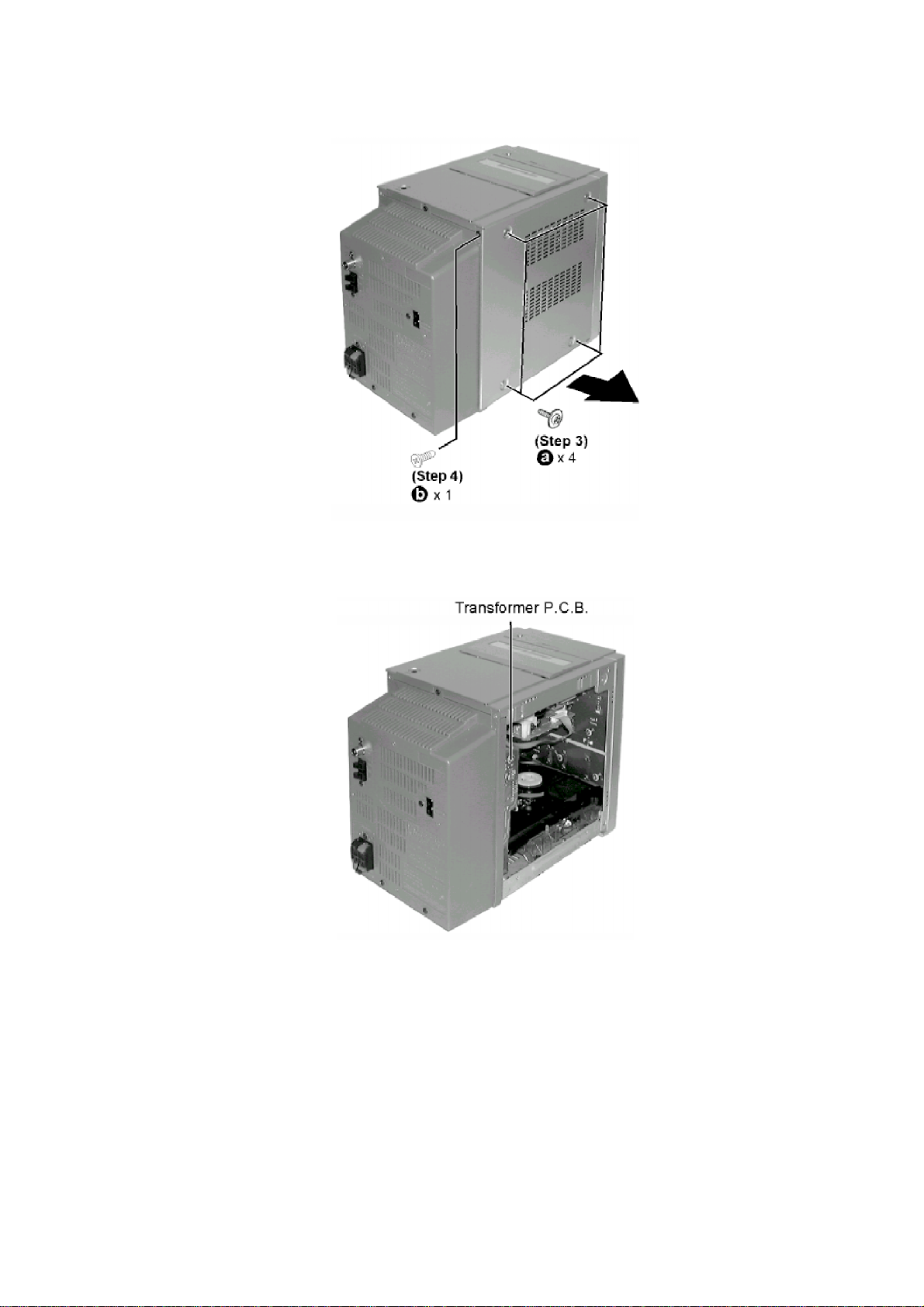
Step 3 Remove all the screws.
Step 4 Remove side panel.
- Checking for Transformer P.C.B.
8.1.2. Checking for the Deck P.C.B., Headphone P.C.B. and Tape Eject P.C.B.
- Follow the (Step 1) - (Step 4) of Item 8.1.1.
Step 1 Remove one screw at the rear chassis.
Step 2 Release claws at both ends.
11
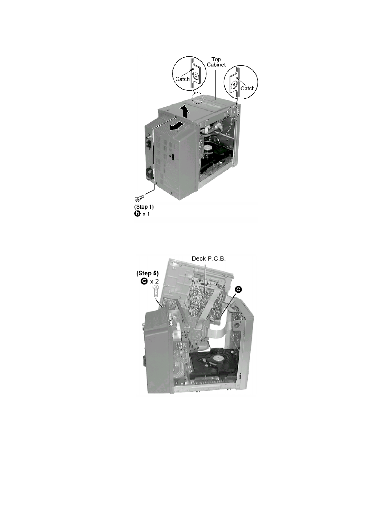
Step 3 Lift up the Top Cabinet and push backward as arrow show.
Step 4 Flip the Top Cabinet sideway.
- Checking For Deck P.C.B.
Step 5 Remove 2 screws.
- Check for Headphone P.C.B. and Tape Eject P.C.B.
12
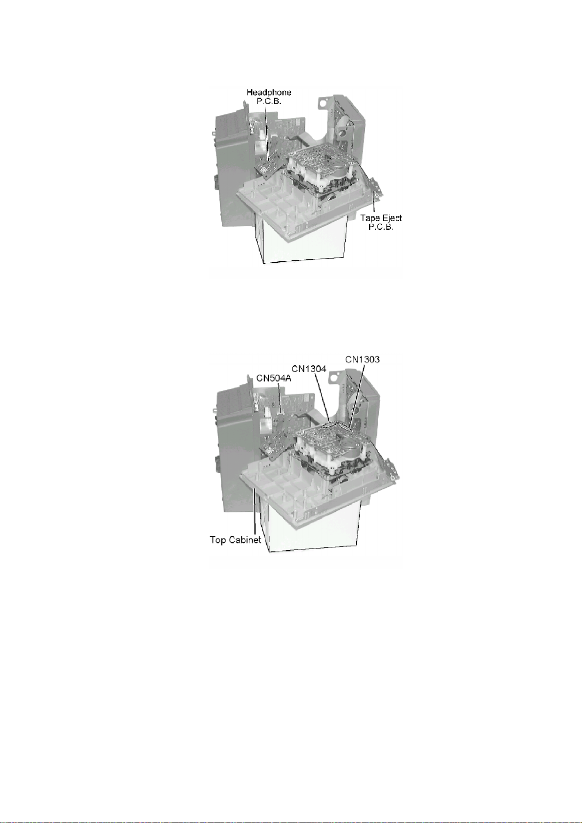
8.1.3. Checking for the Panel P.C.B., Power P.C.B. & Speaker Terminal P.C.B.
- Follow the (Step 1) - (Step 4) of Item 8.1.1.
- Follow the (Step 1) - (Step 4) of Item 8.1.2.
Step 1 To detach top cabinet, release connector CN504A, CN1303 & CN1304.
13
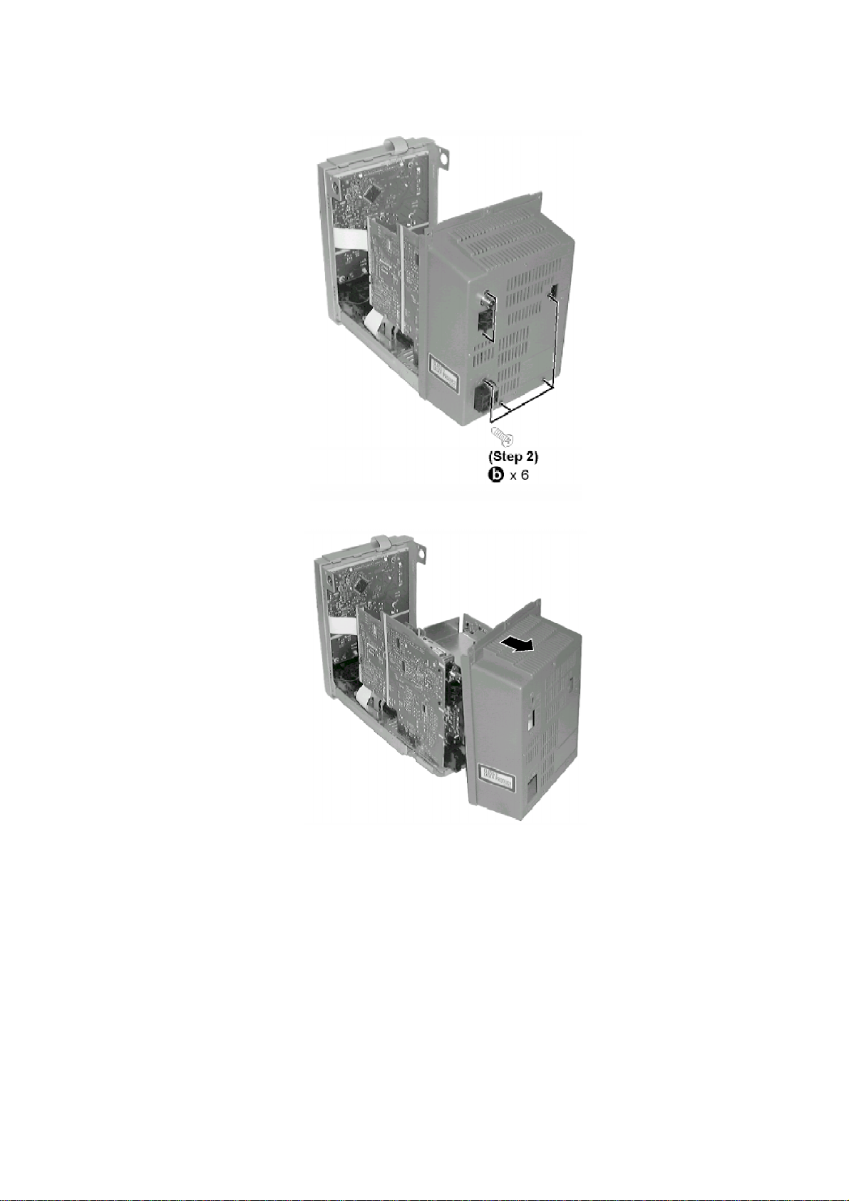
Step 2 Remove 6 screws.
Step 3 Pull back panel in the direction of the arrow shown.
- Check the Panel P.C.B. and Power P.C.B.
14

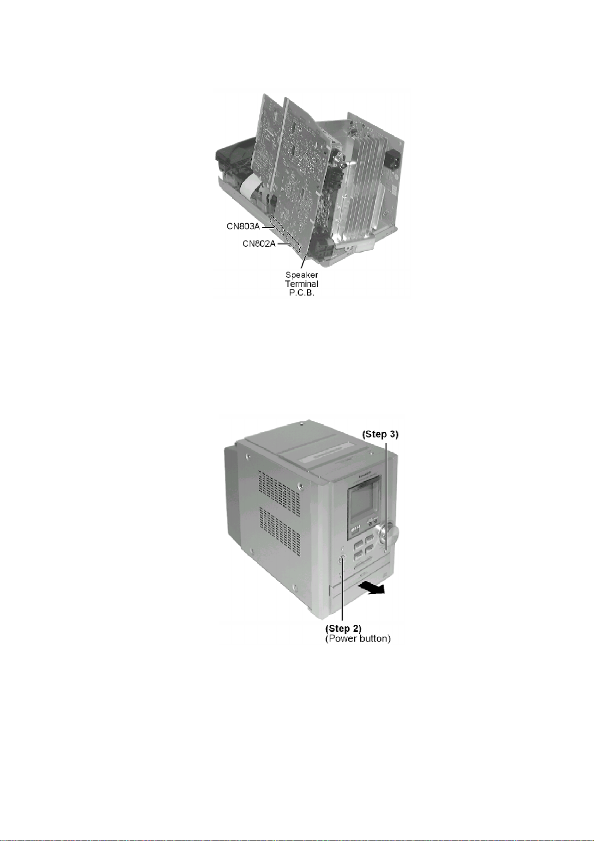
Step 4 Release 2 connectors (CN802A & CN803A).
Step 5 Pull the Main P.C.B. upward
- Checking for Speaker Terminal P.C.B.
Step 6 Pull out Main P.C.B.
Step 7 Remove 2 screws.
15
Step 8 Reconnect 2 connectors (CN802A & CN803A).
[For operation checking of main unit]
Step 9 Reverse Step 1 of Item 8.1.3. to attach top cabinet. (Deck mechanism)
- Replacement of CD Lid
When opening the disc tray automatically (Using Power Supply)
Step 1 Connect AC power cord.
Step 2 Press the POWER button to power up the main unit.
Step 3 Press the OPEN button, the disc tray will open automatically.
Step 4 Release the 2 claws, and then remove the CD lid.
16
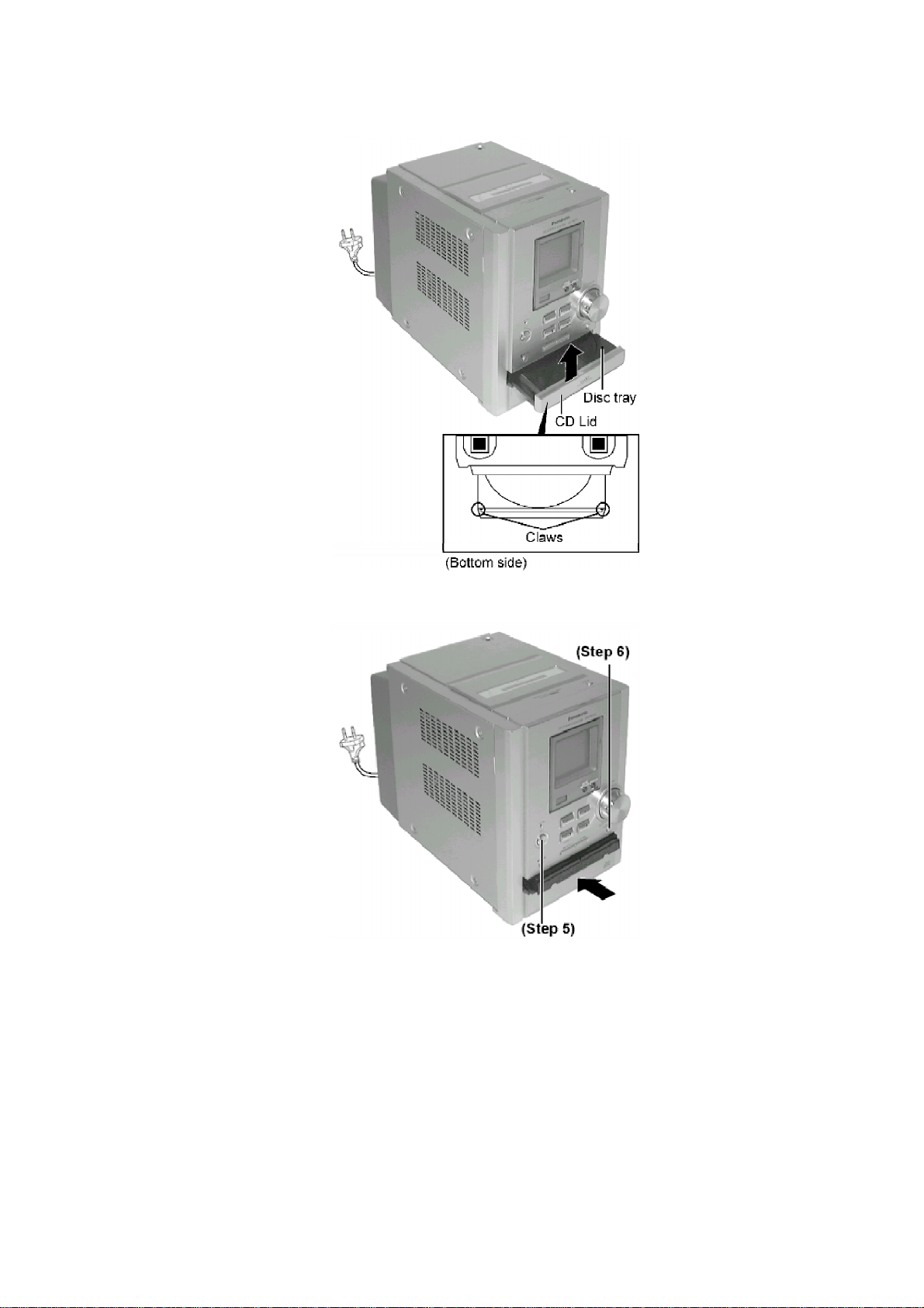
Step 5 Press the POWER button to turn the power only.
Step 6 Press the OPEN/CLOSE button, the disc tray will be close.
[Open the disc tray manually (Using service tools)]
- Follow the (Step 1) - (Step 4) of Item 8.1.1.
- Follow the (Step 1) - (Step 4) of Item 8.1.2.
- Follow the (Step 1) of Item 8.2.1.
8.1.4. Checking for the CD Servo P.C.B.
- Follow the (Step 1) - (Step 4) of Item 8.1.1.
- Follow the (Step 1) - (Step 5) of Item 8.1.2.
- Follow the (Step 1) - (Step 9) of Item 8.1.3.
17
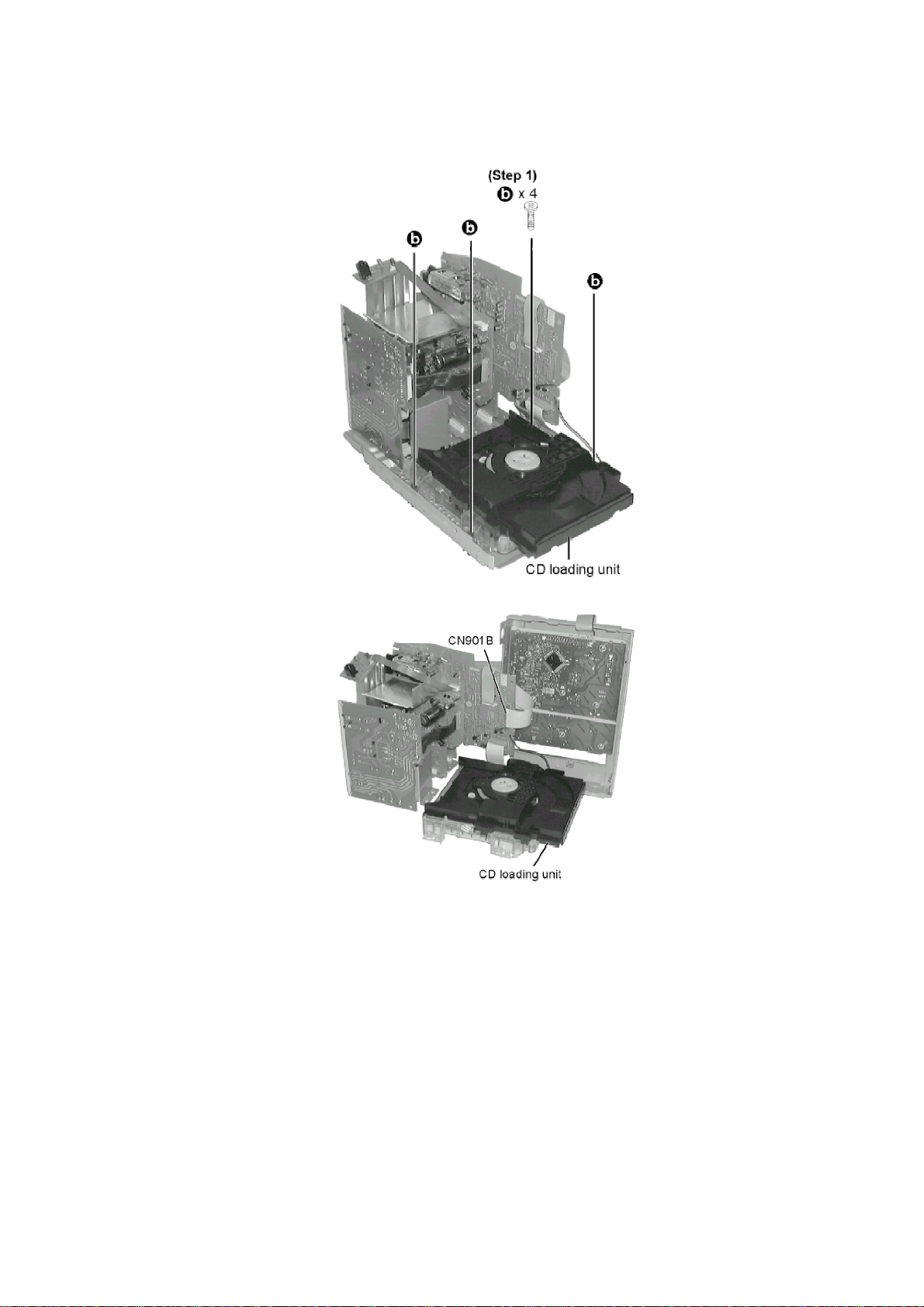
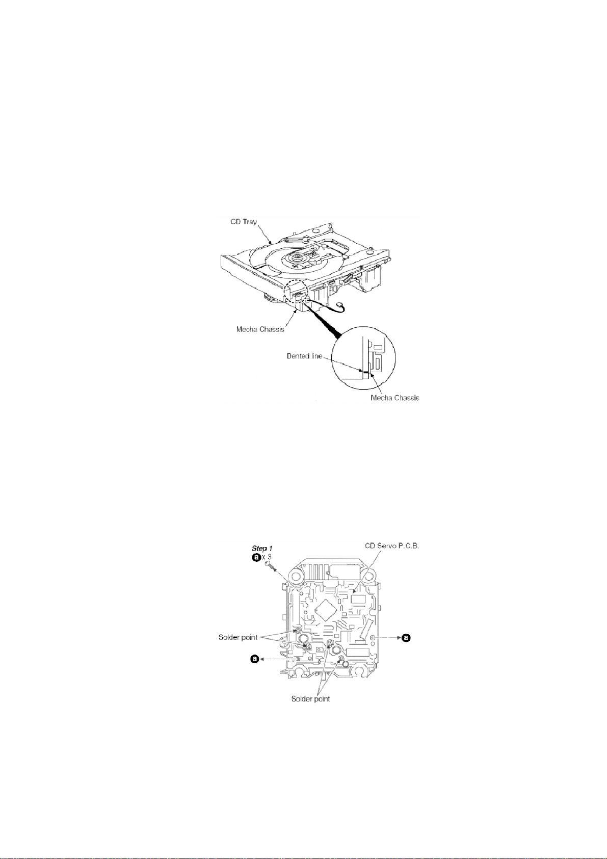
Step 1 Remove all screws.
Step 2 Connect CN901B as shown.
- Checking CD Servo P.C.B.
18
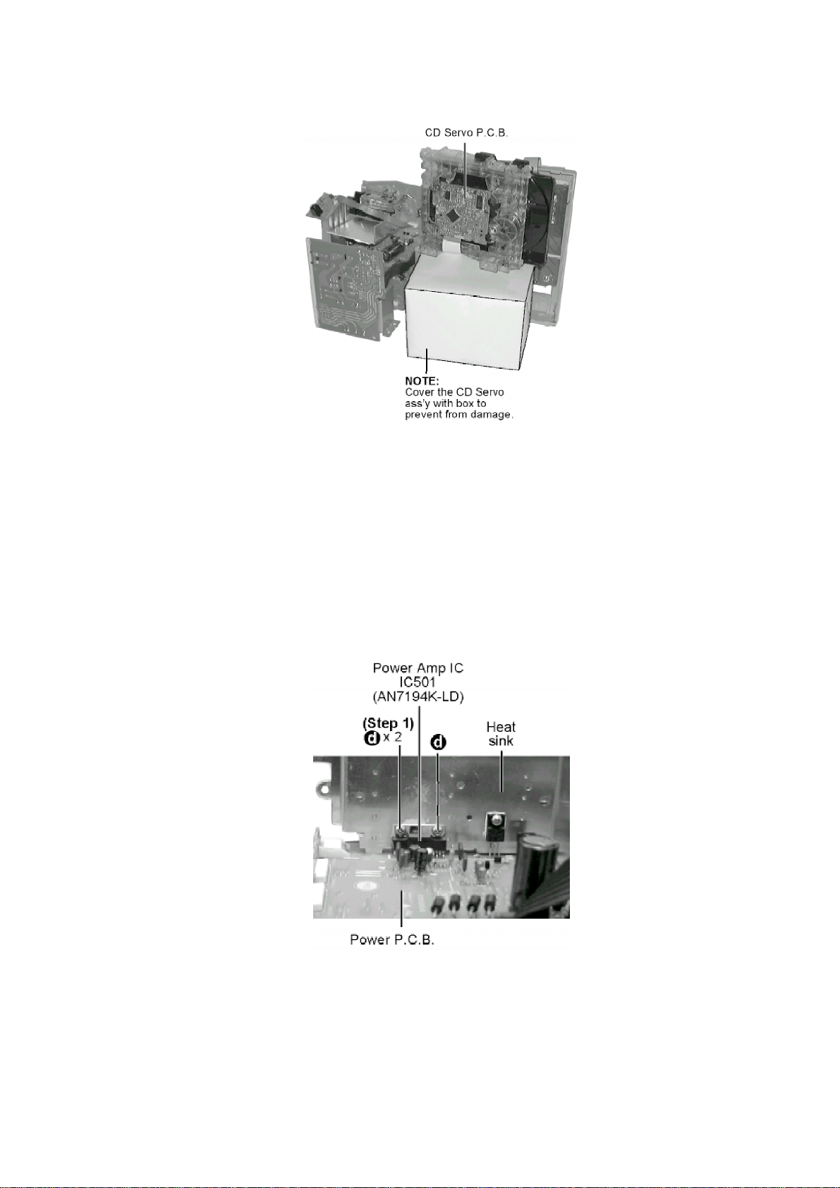
Step 3 Lift up the Main P.C.B. together with the Power P.C.B. and rotate left then place the p.c.b.
as shown in the following figure.
[Service Position]
8.1.5. Replacement of the Power Amplifier IC
- Replacement of the Power Amplifier IC
- Follow the (Step 1) - (Step 4) of Item 8.1.1.
- Follow the (Step 1) - (Step 5) of Item 8.1.2.
- Follow the (Step 1) - (Step 8) of Item 8.1.3.
- Follow the (Step 1) - (Step 3) of Item 8.1.4.
Step 1 Remove 2 screws fixed to the Power Amp I.C.
19

Step 2 Unsolder the terminals of Power Amp IC, transistor and replace the component.
8.2. Disassembly and Assembly of the Disc Tray and CD Traverse
Unit
- Follow the (Step 1) - (Step 4) of Item 8.1.1.
- Follow the (Step 1) - (Step 5) of Item 8.1.2.
- Follow the (Step 1) - (Step 9) of Item 8.1.3.
- Follow the (Step 1) - (Step 3) of Item 8.1.4.
8.2.1. Disassembly of the Disc Tray.
Step 1 Turn the gear counter clock wise until the CD Tray starts to move out.
20
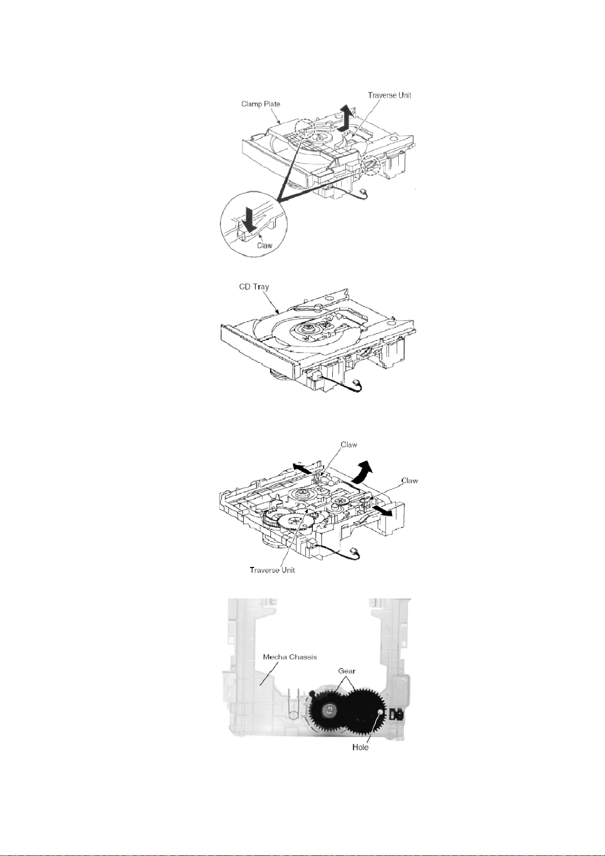
Step 2 Release the 2 claws and remove the clamp plate in the direction of the arrow.
Step 3 Lift up the CD Tray to remove it.
8.2.2. Disassembly of the CD Traverse Unit.
Step 1 Release the 2 claws and remove the CD Traverse Unit in the direction of the arrow.
21
NOTE:
1. Follow the reverse procedure to replace the CD Traverse Unit and
CD Tray.
2. Make sure that the 2 gear is in position shown above and the hole
on the right gear is align with the hole below it when replacing the
CD Traverse Unit and CD Tray.
NOTE: When replacing the CD Tray, make sure the Dented line is at the position as shown.
8.3. Main Component Replacement Procedure
- Follow the (Step 1) - (Step 4) of Item 8.1.1.
- Follow the (Step 1) - (Step 5) of Item 8.1.2.
- Follow the (Step 1) - (Step 9) of Item 8.1.3.
- Follow the (Step 1) - (Step 3) of Item 8.1.4.
8.3.1. Replacement of the CD Servo P.C.B. and Optical Pick-up Unit.
Step 2 Desolder the 4 legs of 2 motors and flip over the CD Servo P.C.B.
Step 3 Remove the flexible cable at CN701.
- Removal of the flexible cable / Push the top of the connector in the
22
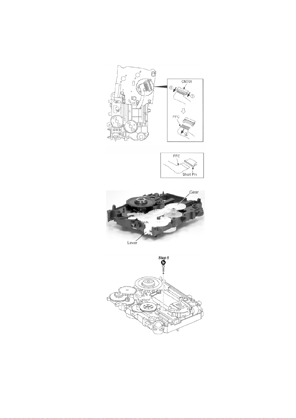
direction of the arrow 1 and then pull out the flexible cable in the
direction of the arrow 2.
NOTE: Insert a short pin into the flexible cable.
Step 4 Push the lever in and turn the gear clock wise fully.
23
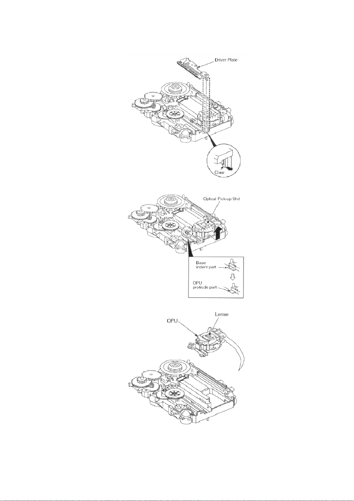
Step 6 Release the claw and remove the Driver Plate.
Step 7 Slide out the Optical Pick-up Unit from the indent opening.
NOTE: Do not touch the Lense on the OPU.
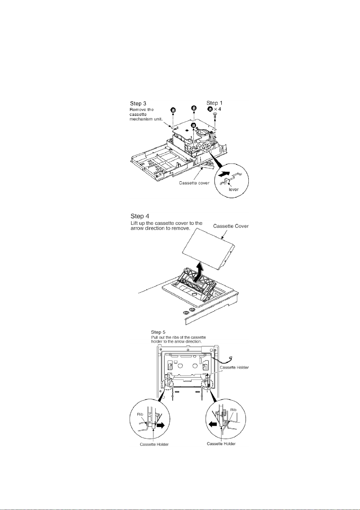
8.4. Procedure for Replacing Cassette Holder
24
- Follow the (Step 1) - (Step 4) of Item 8.1.1.
- Follow the (Step 1) - (Step 5) of Item 8.1.2.
- Follow the (Step 1) - (Step 9) of Item 8.1.3.
- Follow the (Step 1) - (Step 3) of Item 8.1.4.
Step 2 Press the lever to open the cassette cover.
25

8.5. Procedure for Replacing Pinch Roller and Head Block (Cassette
Mechanism Unit)
- Follow the (Step 1) - (Step 4) of Item 8.1.1.
- Follow the (Step 1) - (Step 5) of Item 8.1.2.
- Follow the (Step 1) - (Step 9) of Item 8.1.3.
- Follow the (Step 1) - (Step 3) of Item 8.1.4.
26

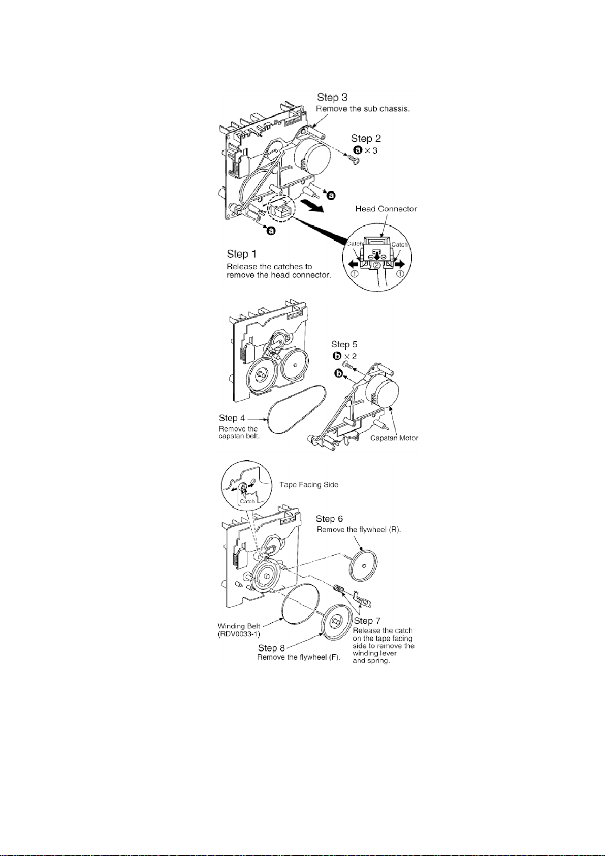
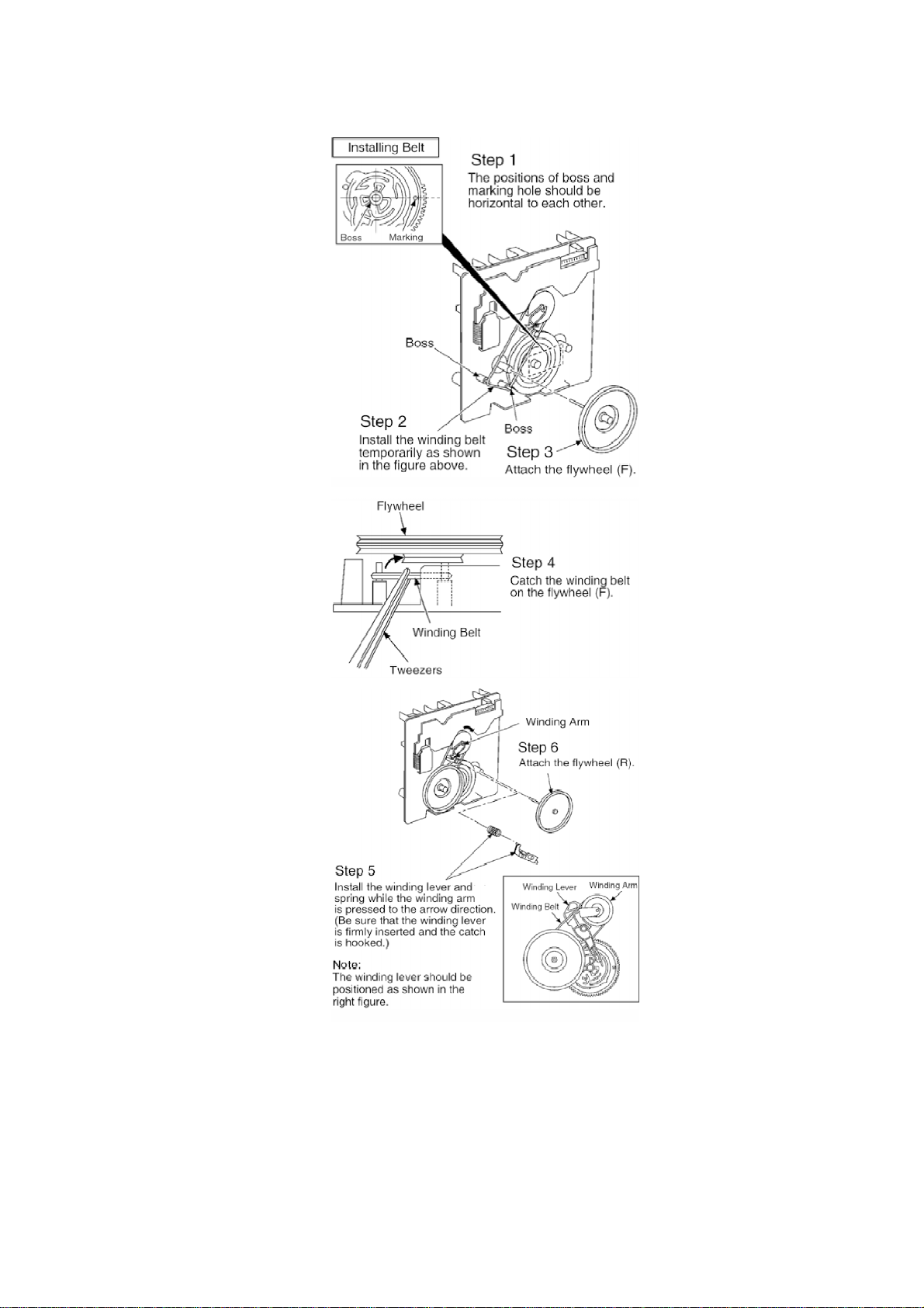
8.6. Procedure for Replacing Motor, Capstan Belt A, Capstan Belt B,
and Winding Belt (Cassette Mechanism Unit)
- Follow the (Step 1) - (Step 4) of Item 8.1.1.
- Follow the (Step 1) - (Step 5) of Item 8.1.2.
- Follow the (Step 1) - (Step 9) of Item 8.1.3.
- Follow the (Step 1) - (Step 3) of Item 8.1.4.
272829

8.7. Procedure for Replacing Parts on Mechanism PCB
- Follow the (Step 1) - (Step 4) of Item 8.1.1.
30
 Loading...