


Technicians
Handbook
for
Sanyo
Ductless
Mini-Splits

Sanyo Contact Information
Technical Support Phone #: (800) 851-1235
Hours of Operation:
Mon-Fri 8:30 am - 5:0
Sanyo Website: www.sanyohvac.c
0 pm E.S.T
om
Sanyo Commercial Solutions (HVAC D
1165 Allgood Rd. Ste. 22
Marietta, Ga. 30062
ivision)
2

r
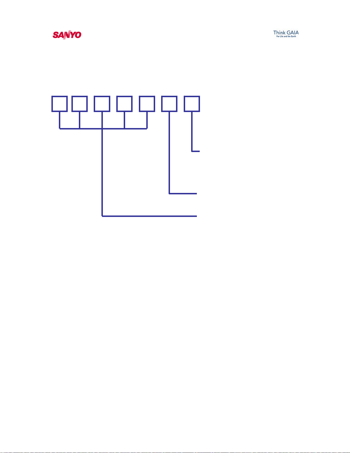
System Model Identification
18
K
H S
7
2
Voltage:
1: 115 VAC
2 : 208/230 VAC
Series of Mod
Controller Type or
S
H: Electric Heater
: Wireless Remote Control
Basic Design
H: Heat Pump
L: Low Ambient
Single Zone or Multi Zone
Blank: Single Zone
M: Multi Zone
el:
Heate
System T ype:
X: 4 Way Ceiling Recessed Cassette
U: Ducted - Concealed
K: Wall Mounted
: Ceiling Suspended T
Capacity in BTU’s
3
Serial Number Identification
0
0
2
3 6 8
1
Quarter of Year:
1: Jan - Mar
2: Apr - Jun
3: Jul - Sep
4: Oct - Dec
Year of Manufact
ecutive Sequence
Cons
Number
ure
anyo warrantees the compressor for a period of
S
(6) years and all parts for (1) year.
4

Electrical Requirements for Sanyo RAC models
A
ll of the following models are operated off of a
single source single phase power supply of either 1
15
VAC or 208/230 VAC and require a 20 amp circuit
breaker. Please note our 9,000 & 12,000 single spli
models in a cooling only or heat pump model will
operate off of 115 VAC. The voltage of any Sanyo
system will always be listed by the last number in
the model. Example: 12KS71 would require a 115
volt power supply system and a 26KS72R would
require a 208/230 volt power supply.
Sanyo System Model Numbers (RAC Products)
9KS71, 09KLS71, 09KHS71, 12KS71, 12KLS71,
0
t
12KHS71, 18KS72, 18KLS72, 18KHS72, 24KS72,
24KLS72, 24KHS72, CM1972, CLM1972,
CMH1972, CM2472, CLM2472, CMH2472
,
CM3172, CLM3172, CMH3172.
5
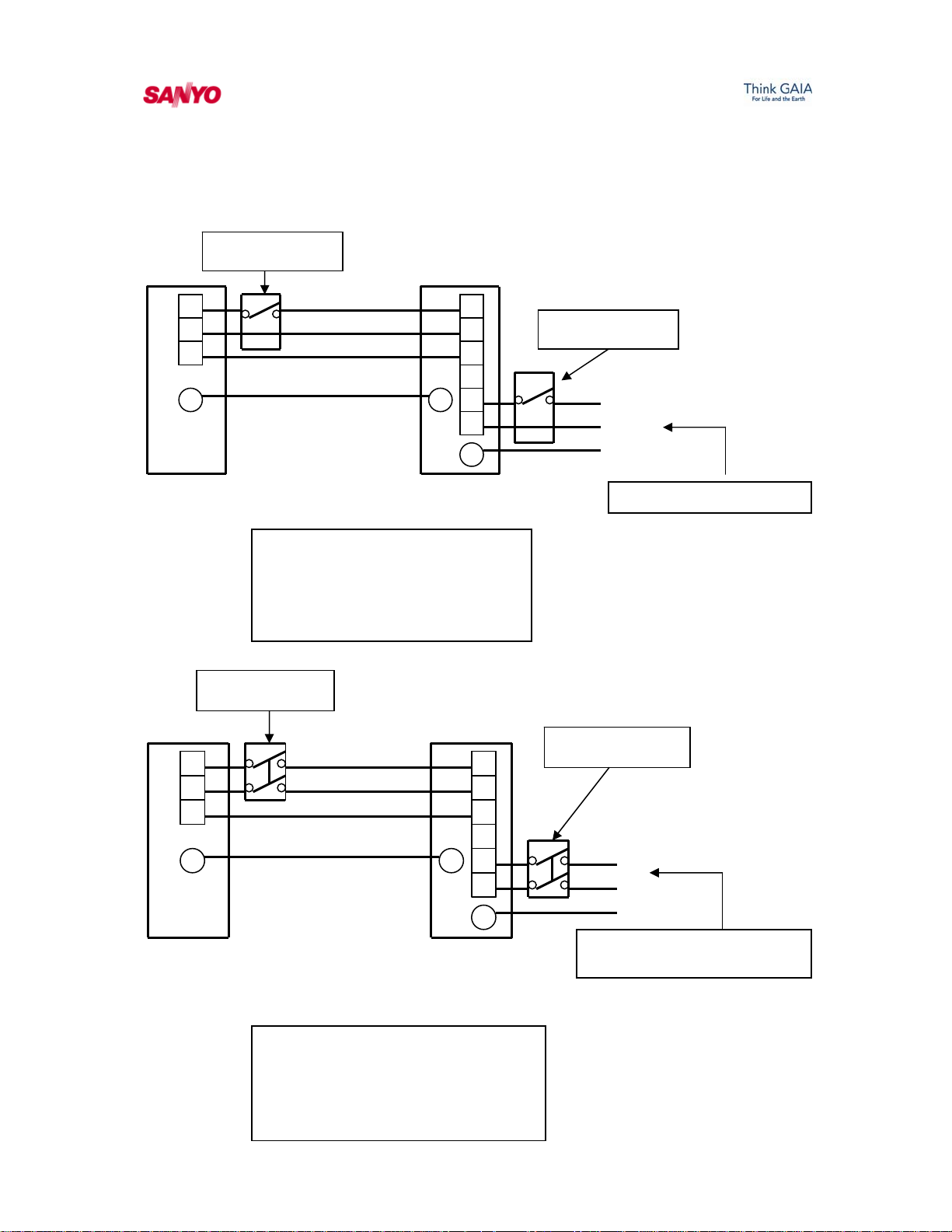
The following are illustrations of Sanyo installation wiring
pump sy
to the outdoor unit.
Disconnect Switch
(Field Supplied)
Fig. 1
oor diagrams. The below all require a 14-3 AWG wire from the ind
1
2
3
G G
Indoor Unit
Disconnect Switch
(Field Supplied)
1
2
3
G G
Indoor Unit
Hot
Neu
tral
12-15 VDC Signal
1
2
3
4
5
6
G
Outd Unit oor
115 VAC installation
ingle wiring diagram for a s
split air conditioning or
stem.
1
Outdoor Unit
heat
115V
115V
12-1 ignal 5 VDC S
2
3
4
5
6
G
Disconnect Switch
(Field Supplied)
Hot
ral
Neut
Ground
115 VAC (Power Supply)
Disconnect Switch
(Field Supplied)
L1
L2
und
Gro
208/ (Single Phase)
230 VAC
y
Power Suppl
Fig. 2
230 VAC installation wiring
diagram for a single split
system air conditioning or
heat pump system.
6

The below diagram is an illustration showing the installation
wiring for a Sanyo flexi-multi system. These systems require
a 14-3 AWG wire from the indoor to the outdoor unit.
Disco
(Field Supplied)
nnect Switch
Fig.3
Outdoor Unit
115 V
115 V
12 C
-15 VD
1
2
3
G
“A”
Indoor Unit “A”
1
2
3
G
Indoor Unit “B”
Indoor Unit “C”
1
2
3
G
1
2
3
115 V
115 V
12 C
-15 VD
115 V
115 V
12 C
-15 VD
230 VAC installation
wiring diagram for a
Flexi-multi
air conditioning or heat
pump system.
4
5
6
G
7
8
9
G G
“B”
“C”
1
2
G
Disconnect Switch
Field Supplied
208/230
Power Supply
L1
L2
Ground
VAC (Single Phase)
7
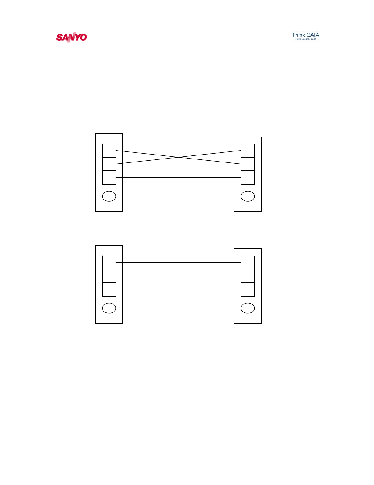
Typical installation wiring errors (208/230 volt system)
he below examples will show an error code of E01)
(T
Indoor Unit
Outdoor Unit
1
2
3
1
2
3
Example: The wires landed on terminals 1 & 2 are crossed
from the indoor to the outdoor unit.
G G
Indoor Unit
Outdoor Unit
1 1
2
3
X
2
3
G G
Example: The wire landed on terminal # 3 is open or shorted.
8

Troubleshooting Guide for 9,000 – 24,000 BTU models & Flexi-multi
¾ Always verify the incoming power at terminals 1 & 2 of the
indoor unit. This voltage will be 115 VAC or 208/230 VAC
depending on the model installed.
¾ All Sanyo indoor printed circuit bo
ards will incorporate a fuse
for overload protection. Verify continuity through this fuse.
¾ Anytime there is a “blinking” green operation lamp on the
front of the indoor unit the system has seen some type of
faulted condition.
¾ The indoor board c
an store up to (3) error codes. The remote is
used in conjunction with the indoor unit’s Operation, Timer &
Quiet lamps to determine the fault code. These lamps are
located in the lower right hand corner of the indoor unit.
¾ On a new installation and the outdoor unit will not operate
.
Always verify the interconnecting wires which run from the
indoor to the outdoor unit.
¾ The following Sanyo models
have a built in outdoor ambient
lock out the C0971, C1271, C1872, C2472, CM1972, CM2472,
CM3172, CMH1972, CMH2472 and CMH3172. These units
will lock out when the outdoor ambient temperature drops
below 50 degrees Fahrenheit.
¾ The outdoor circuit boards inc
orporate a fuse on the circuit
board for overload protection. Verify the continuity through
this fuse.
¾ The Sanyo
outdoor circuit boards utilize a power lamp to
indicate when the board is being powered with the proper
voltage. If this light is not illuminated check the following:
Fuse on the circuit board, verify incoming power supply an
check the reactor for continuity usually around 0.3 Ohms.
¾ The control signal from the indoor to the outdoor unit when
read between terminals 2 & 3 should be reading around 12-15
VDC. This is a pulsating signal which pulses around every 7-8
seconds.
d
9
 Loading...