

Panasonic SAHT-740-P, SAHT-740-PC Service manual
A
ORDER NO.MD0512491C1
A6
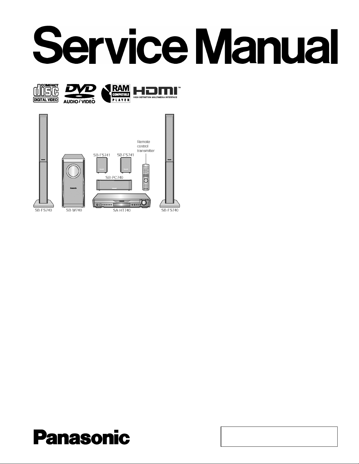
DVD Home Theater Sound System
SA-HT740P
SA-HT740PC
Colour
(S).......................Silver Type
Specifications
lGeneral
Power Source:
Power consumption: 140 W
Dimensions (W×H×D):
Mass:
lAmplifier section
RMS Output Power: Dolby Digital Mode
lTotal RMS Dolby Digital
mode Power:
At 1kHz and total harmonic of 10%
lFront: 90 W/ Channel (4Ω)
lCenter: 320 W/ Channel (4Ω)
lSurround: 90 W/ Channel (4Ω)
At 100Hz and total harmonic of 10%
lActive subwoofers: 320 W/ Channel (4Ω)
FTC Output Power: Dolby Digital Mode:
lTotal FTC Dolby Digital mode Power:
At 120Hz-20kHz and total harmonic of 1%
lFront: 60 W/ Channel (4Ω)
lCenter: 250 W/ Channel (4Ω)
C 120V, 60Hz
430×70×439.2 mm
(16-15/16”×2-3/4”×17-19/64”)
5 kg (11.02Ibs)
1000 W
740 W
lSurround: 60 W/ Channel (4Ω)
At 45Hz-120Hz and total harmonic of 1%
lSubwoofer: 250 W/ Channel (4Ω)
lFM tuner section
Frequency Range:
Sensitivity: 2.5µV (IHF)
S/N 26dB
Antenna Terminals: 75Ω (unbalanced)
lAM tuner section
Frequency Range: 520-1710kHz (10kHz in step)
AM Sensitivity S/N 20dB at
1000kHz:
lPhone Jack:
Terminal:
lFront M. Port:
Sensitivity: 100mV (4.7kΩ)
Terminal (Input): Stereo 3.5 mm (1/8”) jack
lDisc section
Discs played [8 cm (3”) or 12 cm (5”)]:
87.9-107.9MHz
(200kHz in step)
87.5-108.0MHz
(100kHz in step)
2.2µV
560µV/m
Stereo 3.5 mm (1/8”) jack
© 2006 Panasonic AVC Networks Singapore Pte.
Ltd. All rights reserved. Unauthorized copying and
distribution is a violation of law.
V
Y
Y
SA-HT740P / SA-HT740 PC
(1) DVD-RAM (DVD-VR compatible, JPEG formatted discs)
(2) DVD-Audio
(3) DVD-Video
(4) DVD-R, DVD-RW (DVD-Video, DVD-VR compatible)
+R, +RW (Video compatible)
(5) CD-Audio (CD-DA)
(6) Video CD
(7) SVCD (Conforming to IEC62107)
(8) CD-R/CD-RW (CD-DA, Video-CD, SVCD, MP3, WMA, JPEG
formatted discs)
(9) MP3/WMA
lMPEG-1 Layer 3, MPEG-2 Layer3
lWindows Media Audio Ver. 9.0 L3
Not compatible with Multiple Bit Rate (MBR)
lMaximum number of recognizable audio and picture
contents and groups:
(10) JPEG
lExif Ver 2.1 JPEG Baseline files
lPicture resolution: between 160 x 120 and 6144 x 4096
pixels (Sub sampling is 4:2:2 or 4:2:0). Extremely long and
thin pictures may not be displayed.
lMaximum number of recognizable audio and picture
contents and groups:
(11) HighMAT Level 2 (Audio and lmage)
Pick up:
Wavelength:
lCD: 785nm
lDVD: 662nm
Laser power:
lCD/DVD: (P) CLASS I/CLASS II
lCD/DVD: (PC) CLASS 1M/CLASS 1
Audio output (DISC):
Number of channels: 5.1 ch (FL, FR, C, SL, SR,
Audio performance:
Frequency response:
DVD (linear audio): 4 Hz-22 kHz (48 kHz sampling)
DVD-Audio: 4 Hz-88 kHz (192 kHz
CD-Audio: 4 Hz-20 kHz
S/N ratio:
CD-Audio: 105 dB
Dynamic range:
DVD (linear audio): 95 dB
CD-Audio: 93 dB
Total harmonic distortion:
CD-Audio: 0.005 %
lVideo section
ideo system:
Signal system: NTSC
Composite video output:
Output level: 1 Vp-p (75 Ω )
4000 audio and picture contents and 400 groups
4000 audio and picture contents and 400 groups
SW)
4 Hz-44 kHz (96 kHz sampling)
sampling)
Terminal: Pin jack (1 system)
S-video output:
output level: 1 Vp-p (75 Ω )
C output level: NTSC; 0.286 Vp-p (75 Ω)
Terminal S terminal (1 system)
Component video output (480p/480i):
output level: 1 Vp-p (75 Ω )
PBoutput level: 0.7 Vp-p (75 Ω )
PRoutput level: 0.7 Vp-p (75 Ω )
Terminal: Pin jack (Y: green, PB: blue,
P
: red) (1 system)
R
HDMI AV output:
19 pin type A connector, HDMI
Ver.1.2a (EDID Ver.1.3)
Power consumption in standby mode:
approx 0.4W
Note:
1. Specifications are subject to change without notice.
Mass and dimensions are approximate.
2. Total harmonic distortion is measured by the digital spectrum
analyzer.
Solder:
This model uses lead free solder (PbF).
Mechanism:
This model uses RC1 (Rotary tray) machanism.
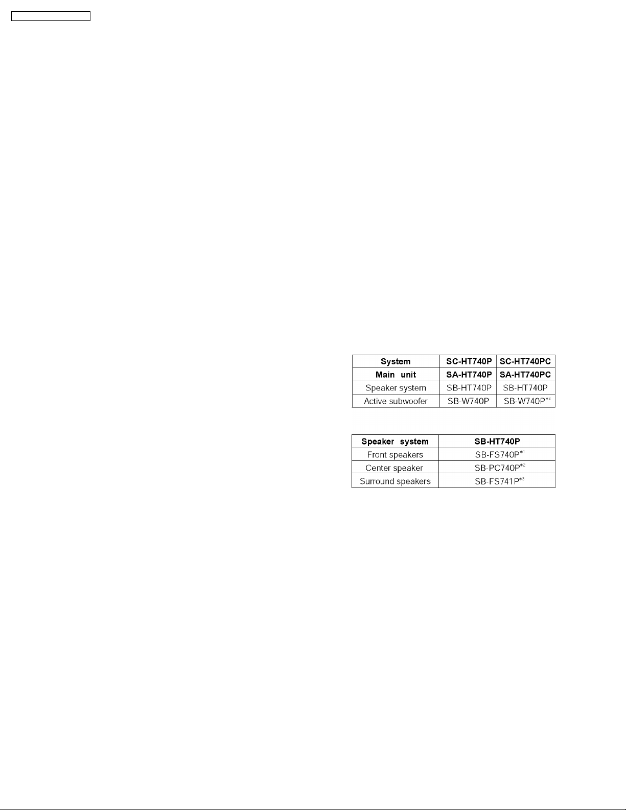
Refer to the original service manual for *1, *2, *3, *4.
2
SA-HT740P / SA-HT740 PC
CONTENTS
Page Page
1 Safety Precautions 5
1.1. GENERAL GUIDELINES
1.2. Before Repair and Adjustment
1.3. Protection Circuitry
2 Prevention of Electro Static Discharge (ESD) to
Electrostatically Sensitive (ES) Devices
3 Precaution of Laser Diode
4 About Lead Free Solder (PbF)
5 Handling Precautions for Traverse Unit
5.1. Cautions to Be Taken in Handling the Optical Pickup Unit
5.2. Grounding for electrostatic breakdown prevention
6 Accessories
7 Operation Procedures
7.1. Remote Control Keys Operation
7.2. Main Unit Keys Operation
7.3. Disc information
8 New Features
8.1. Using of Receiver Unit (SH-FX60 / SH-FX80)
8.2. About HDMI
9 Self-Diagnosis and special mode setting
9.1. Service Mode Summary Table
9.2. Service Mode Table 1
9.3. DVD Self Diagnostic Function-Error Code
11
12
12
13
14
16
16
20
22
22
22
27
5
5
6
6
8
8
9
9
9
9.4. Sales Demonstration Lock Function 29
9.5. Service Precautions
10 Assembling and Disassemb ling
10.1. Disassembly Flow Chart
10.2. Main Components and P.C.B. Locations
10.3. Disassembling the Top Cabinet
10.4. Disassembling the Front Panel Assembly
10.5. Disassembling the Tray Assembly
10.6. Disassembling the Rear Panel
10.7. Disassembling the Mechanism Base Assembly
10.8. Disassembling the FL & Head phone P.C.B.
10.9. Disassembling the HDMI Module P.C.B.
10.10. Disassembling the Regulator P.C.B.
10.11. Disassembling the Main P.C.B.
10.12. Disassembling the AC-Inlet, Power & Sub Power P.C.B
10.13. Disassembly of Digital Amp IC
10.14. Disassembly of Regulator IC
10.15. Disassembly of Switch Regulator IC (IC5701)
10.16. Disassembly of the Tray Base Guide (L) and Tray Base
Guide (R)
10.17. Disassembly of the Rotary Tray
10.18. Disassembly of the Traverse Unit
10.19. Assembly of Tray Assembly
30
31
32
32
33
33
33
34
34
34
35
35
35
35
36
36
36
37
37
38
40
3

SA-HT740P / SA-HT740 PC
11 Service Fixture and Tools 42
12 Service Positions
12.1. Checking & Repair Main P.C.B., Power P.C.B., HDMI
Module P.C.B., FL and Head phone P.C.B.
13 Measurements and Adjustments
13.1. Service Tools and Equipment
13.2. Important points in adjustment
13.3. Storing and handling of test discs
13.4. Optical adjustment
13.5. Abbreviations
14 Voltage and Waveform Chart
14.1. HDMI Module P.C.B.
14.2. Main P.C.B.
14.3. Power P.C.B.
14.4. FL P.C.B.
14.5. Loading Motor P.C.B., Tray Motor P.C.B., Sensor P.C.B.,
Regulator P.C.B.
14.6. Waveform Chart
15 Illustration of IC's, Transistors and Diodes
16 Wiring Connection Diagram
17 Block Diagram
18 Schematic Diagram
18.1. (A) HDMI Module Circuit
18.2. (B) Main Circuit
18.3. (C) Power Circuit
18.4. (C) Panel Circuit
18.5. (D) Loading Motor, Tray Motor, Sensor & Regulator Circuit
42
19 Printed Circuit Board
42
43
43
43
43
44
45
47
47
49
50
50
19.1. (A) HDMI Module P.C.B.
19.2. (B) Main, AC-inlet & Sub-power P.C.B.
19.3. (C) Power P.C.B.
19.4. (E) FL, Headphone, Loading motor, Tray motor, Sensor &
Regulator P.C.B.
20 Basic Troubleshooting Guide
20.1. Basic Troubleshooting Guide for Traverse Unit (HDMI
Module P.C.B)
20.2. Basic Troubleshooting Guide for HDMI AV output
21 Overall Block Diagram for HT740
21.1. HT740 DVD Unit Block Diagram
21.2. HT740 Block Diagram (Analog Signal : DVD 5.1ch Play
Back Mode)
51
52
53
55
57
63
64
70
75
21.3. HT740 Block Diagram (Analog Signal : 2ch Analog Input
Mode)
22 Terminal Function of ICs
22.1. IC2001 (MN101C49GHF): Operation CPU
23 Explode Views
23.1. Cabinet Parts Location
23.2. Packaging
24 Replacement Parts List
24.1. Component Parts List
78
79
81
81
82
83
84
85
85
86
87
88
89
90
91
91
92
92
95
96
97
4
SA-HT740P / SA-HT740 PC
1 Safety Precautions
1.1. GENERAL GUIDELINES
1. When servicing, observe the original lead dress. If a short circuit is found, replace all parts which have been overheated or
damaged by the short circuit.
2. After servicing, see to it that all the protective devices such as insulation barriers, insulation papers shields are properly
installed.
3. After servicing, carry out the following leakage current checks to prevent the customer from being exposed to shock hazards.
1.1.1. LEAKAGE CURRENT COLD CHECK
1. Unplug the AC cord and connect a jumper between the two prongs on the plug.
2. Measure the resistance value, with an ohmmeter, between the jumpered AC plug and each exposed metallic cabinet part on
the equipment such as screwheads, connectors, control shafts, etc. When the exposed metallic part has a return path to the
chassis, the reading should be between 1MΩ and 5.2MΩ.
When the exposed metal does not have a return path to the chassis, the reading must be
.
Figure 1
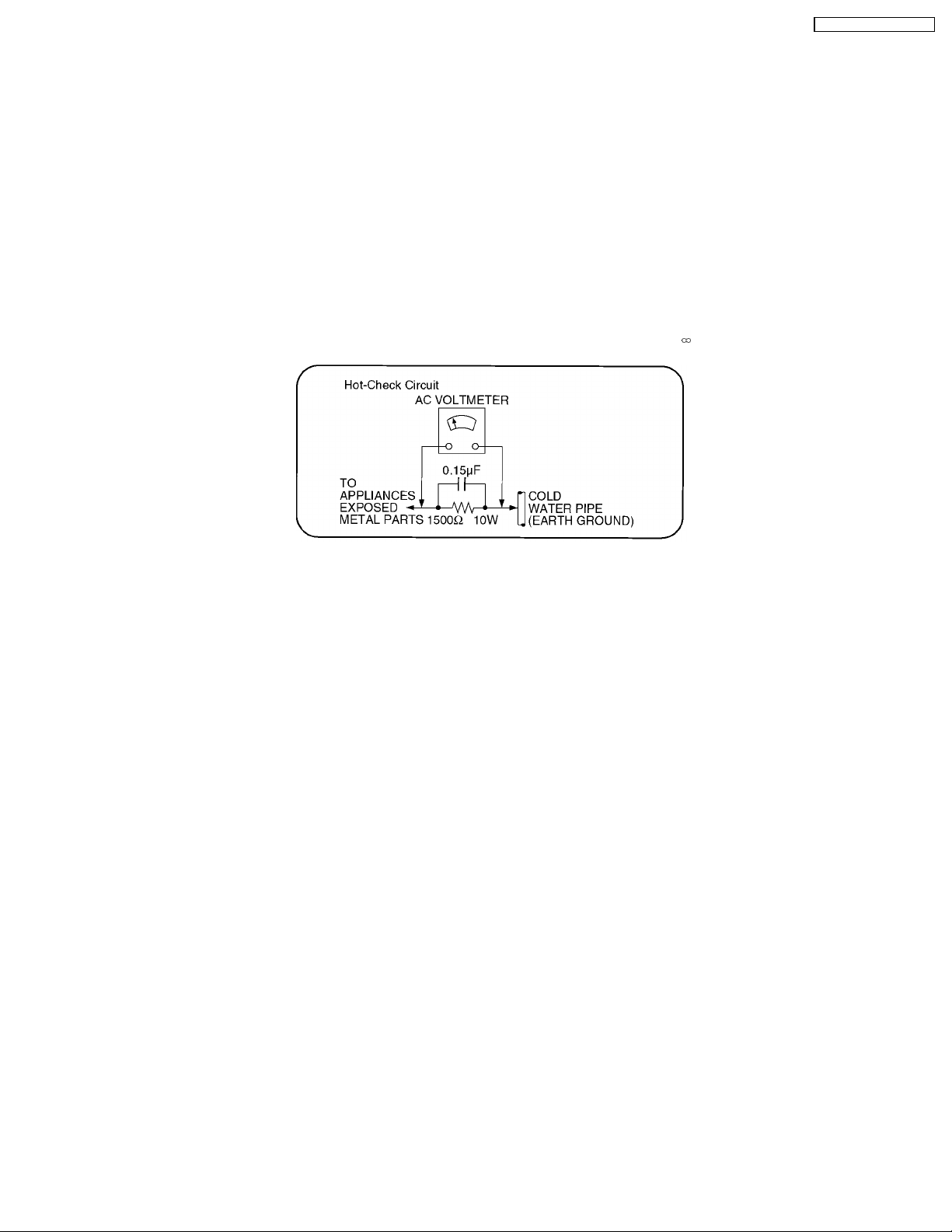
1.1.2. LEAKAGE CURRENT HOT CHECK (See Figure 1.)
1. Plug the AC cord directly into the AC outlet. Do not use an isolation transformer for this check.
2. Connect a 1.5kΩ , 10 watts resistor, in parallel with a 0.15µF capacitors, between each exposed metallic part on the set and a
good earth ground such as a water pipe, as shown in Figure 1.
3. Use an AC voltmeter, with 1000 ohms/volt or more sensitivity, to measure the potential across the resistor.
4. Check each exposed metallic part, and measure the voltage at each point.
5. Reverse the AC plug in the AC outlet and repeat each of the above measurements.
6. The potential at any point should not exceed 0.75 volts RMS. A leakage current tester (Simpson Model 229 or equivalent) may
be used to make the hot checks, leakage current must not exceed 1/2 milliamp. In case a measurement is outside of the limits
specified, there is a possibility of a shock hazard, and the equipment should be repaired and rechecked before it is returned to
the customer.
1.2. Before Repair and Adjustment
Disconnect AC power, discharge Power Supply Capacitors C5736, C5737, C5741, C5742 through a 10 Ω, 10 W resistor to ground.
DO NOT SHORT-CIRCUIT DIRECTLY (with a screwdriver blade, for instance), as this may destroy solid state devices.
After repairs are completed, restore power gradually using a variac, to avoid overcurrent.
Current consumption at AC 120 V, 60 Hz in NO SIGNAL mode volume minimal should be ~ 750 mA.
5

SA-HT740P / SA-HT740 PC
1.2.1. Caution for fuse replacement
1.3. Protection Circuitry
The protection circuitry may have operated if either of the following conditions are noticed:
· No sound is heard when the power is turned on.
· Sound stops during a performance.
The function of this circuitry is to prevent circuitry damage if, for example, the positive and negative speaker connection wires are
“shorted”, or if speaker systems with an impeda nce less than the indicated rated impedance of the amplifier are used.
If this occurs, follow the procedure outlines below:
1. Turn off the power.
2. Determine the cause of the problem and correct it.
3. Turn on the power once again after one minute.
Note:
When the protection circuitry functions, the unit will not operate unless the power is first turned off and then on again.
2 Prevention of Electro Static Discharge (ESD) to
Electrostatically Sensitive (ES) Devices
Some semiconductor (solid state) devices can be damaged easily by static electricity. Such components commonly are called
Electrostatically Sensitive (ES) Devices. Examples of typical ES devices are integrated circuits and some field-effect transistors and
semiconductor "chip" components. The following techniques should be used to help reduce the incidence of component damage
caused by electro static discharge (ESD).
1. Immediately before handling any semiconductor component or semiconducto r-equipped assembly, drain off any ESD on your
body by touchin g a known earth ground. Alternatively, obtain and wear a commercially available discharging ESD wrist strap,
which should be removed for potential shock reasons prior to applying power to the unit under test.
2. After removing an electrical assembly equipped with ES devices, place the assembly on a conductive surface such as
aluminum foil, to prevent electrostatic charge buildup or exposure of the assembly.
3. Use only a grounded-tip soldering iron to solder or unsolder ES devices.
4. Use only an anti-static solder removal device. Some solder removal devices not classified as "anti-static (ESD protected)" can
generate electrical charge sufficient to damage ES devices.
5. Do not use freon-propelle d chemicals. These can generate electrical charges sufficie nt to damage ES devices.
6. Do not remove a replacement ES device from its protective package until immediately before you are ready to install it. (Most
replacement ES devices are packaged with leads electrically shorted together by conductive foam, aluminum foil or comparable
conductive material).
7. Immediately before removing the protective material from the leads of a replacement ES device, touch the protective material
to the chassis or circuit assembly into which the device will be installed.
Caution
Be sure no power is applied to the chassis or circuit, and observe all other safety precautions.
8. Minimize bodily motions when handling unpackaged replacement ES devices. (Otherwise harmless motion such as the
brushing together of your clothes fabric or the lifting of your foot from a carpeted floor can generate static electricity (ESD)
sufficient to damage an ES device).
6

SA-HT740P / SA-HT740 PC
7
SA-HT740P / SA-HT740 PC
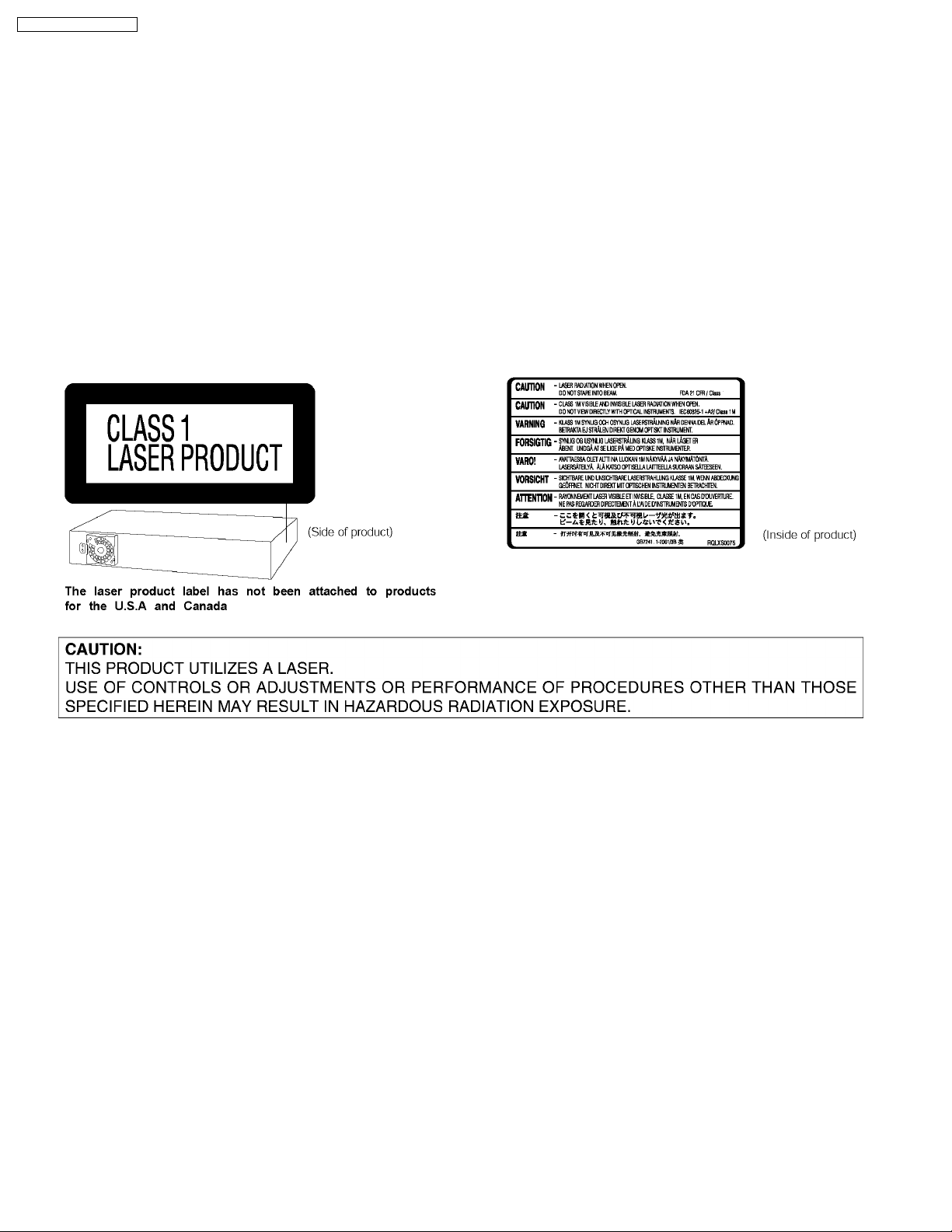
3 Precaution of Laser Diode
CAUTION:
This unit utilizes a class 1 laser.
Invisible laser radiation is emitted from the optical pickup lens.
Wavelength: 662nm(DVD)/785nm(CD).
Maximum output radiation power from pickup: 100µW/VDE
When the unit is turned on:
1. Do not look directly into the pick up lens.
2. Do not use optical instruments to look at the pick up lens.
3. Do not adjust the preset variable resistor on the pickup lens.
4. Do not disassemble the optical pick up unit.
5. If the optical pick up is replaced, use the manufacturer’s specified replacement pick up only.
6. Use of control or adjustments or performance of procedures other than those specified herein may result in hazardous
radiation exposure.
4 About Lead Free Solder (PbF)
Distinction of PbF PCB: PCBs (manufacture d) using lead free solder will have a PbF stamp on the PCB.
Caution:
· Pb free solder has a higher melting point than standard solder; Typically the melting point is 50 - 70°F (30 - 40°C) higher.
Please use a high temperature soldering iron. In case of the soldering iron with temperature control, please set it to 700 ±
20°F (370 ± 10°C).
· Pb free solder will tend to splash when heated too high (about 1100°F/ 600°C).
When soldering or unsoldering, please completely remove all of the solder on the pins or solder area, and be sure to heat the
soldering points with the Pb free solder until it melts enough.
8
SA-HT740P / SA-HT740 PC
5 Handling Precautions for Traverse Unit
The laser diode in the optical pickup unit may break down due to static electricity of clothes or human body. Special care must be
taken avoid caution to electrostatic breakdown when servicing and handling the laser diode.
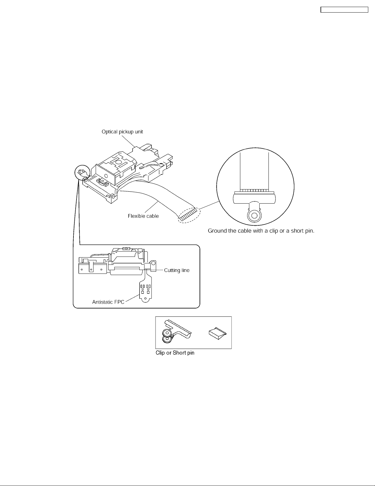
5.1. Cautions to Be Taken in Handling the Optical Pickup Unit
The laser diode in the optical pickup unit may be damaged due to electrostatic discharge generating from clothes or human body.
Special care must be taken avoid caution to electrostatic discharge damage when servicing the laser diode.
1. Do not give a considerable shock to the optical pickup unit as it has an extremely high-precise structure.
2. To prevent the laser diode from the electrostatic discharge damage, the flexible cable of the optical pickup unit removed should
be short-circuited with a short pin or a clip.
3. The flexible cable may be cut off if an excessive force is applied to it. Use caution when handling the flexible cable.
4. The antistatic FPC is connected to the new optical pickup unit. After replacing the optical pickup unit and connecting the flexible
cable, cut off the antistatic FPC.
5.2. Grounding for electrostatic breakdown prevention
Some devices such as the DVD player use the optical pickup (laser diode) and the optical pickup will be damaged by static
electricity in the working environment. Proceed servicing works under the working environment where grounding works is
completed.
5.2.1. Worktable grounding
1. Put a conductive material (sheet) or iron sheet on the area where the optical pickup is placed, and ground the sheet.
5.2.2. Human body grounding
1. Use the anti-static wrist strap to discharge the static electricity form your body.
9

SA-HT740P / SA-HT740 PC
10
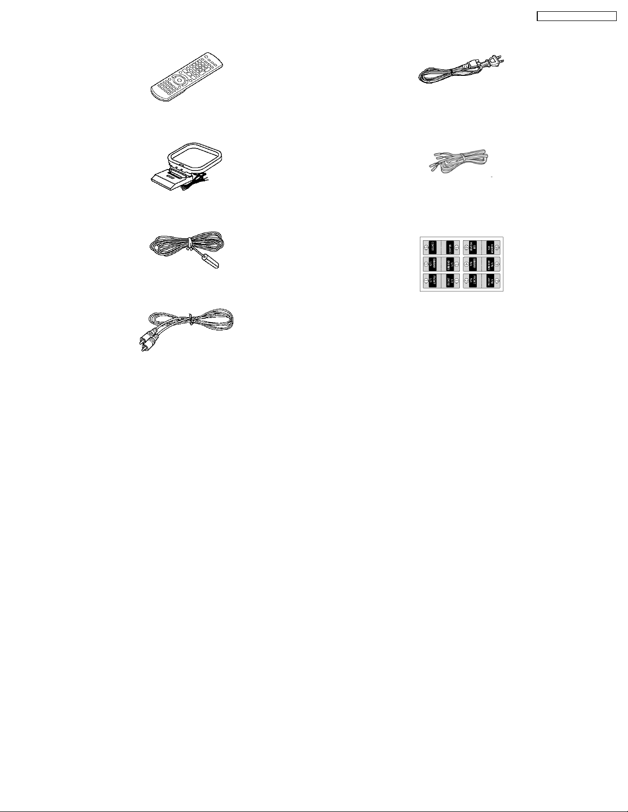
6 Accessories
Remote control
SA-HT740P / SA-HT740 PC
AC cord
AM loop antenna
FM indoor antenna
Video Cable
Speaker cable
Speaker label
11
SA-HT740P / SA-HT740 PC
7 Operation Procedures
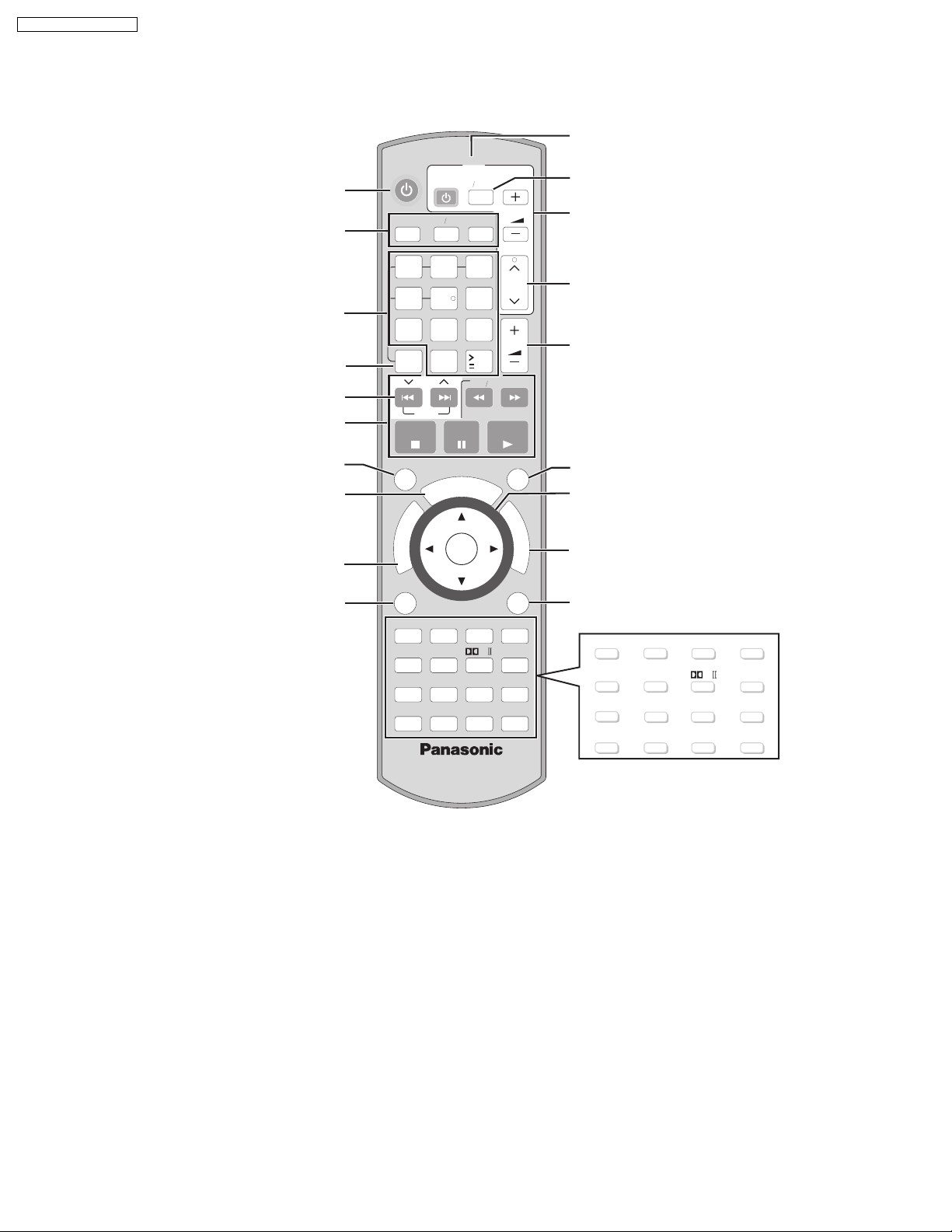
7.1. Remote Control Keys Operation
Television operations
Turn the unit on/off
Select the source
DVD/CD, FM/AM, AUX/FRONT
MUSIC P./REAR MUSIC P.
Select disc's title numbers etc./Enter
numbers
Select the disc or show disc information
Select preset radio stations
Basic operations for play
Select a group of contents to play
Equalizing the sound
Show a disc top menu or program list
Show a disc menu or play list
TV
VIDEOTV
VOLUME
P.
DVD
AM
MUSICFM
AUX
213
CH
54
6
78
DISC
SKIP
STOP
GROUP
R
O
T
A
G
I
V
A
N
T
C
U
E
R
N
I
E
D
M
P
O
T
MENU RETURN
PLAY
LIST
CANCEL
WOOFER
SUB
LEVEL
SLEEP
SETUP
0
U
S
PLAY
ZOOM
TEST
PAUSE
O
R
R
ENTER
MODE
SFC
9
10
SLOW SEARCH
N
D
U
M
U
REPEAT
DISPLAY
FL
CH
SELECT
PL
S
I
PLAY
QUICK
C
VOLUME
OSD
F
U
N
C
T
I
O
N
S
MODE
CD
H.BASS
C.FOCUS
MUTING
Change the television's video input mode
Adjust the television volume
Select television channels
Adjust the volume of the main unit
Display current playback condition
Frame-by-frame/Select or register menu
items on the television screen
Show on-screen menu
Return to previous screen
CANCEL PLAY MODE REPEAT
SUB WOOFER
LEVEL
SLEEP FL DISPLAY
SFC
ZOOM
CD MODE
PL
H.BASS
C.FOCUS
SETUP
TEST
CH SELECT
MUTING
12
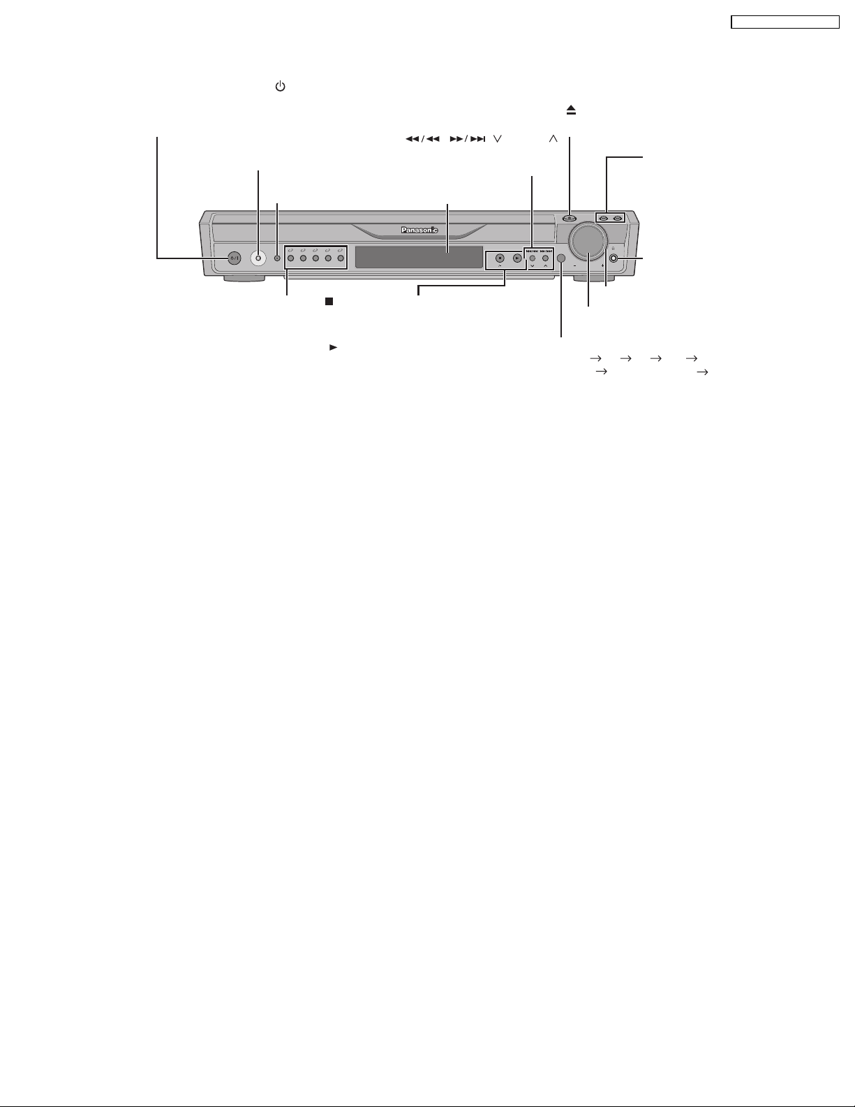
7.2. Main Unit Keys Operation
SA-HT740P / SA-HT740 PC
Standby/on switch [POWER
/I]
Press to switch the unit from on to standby mode
or vice versa. In standby mode, the unit is still
consuming a small amount of power.
MUSIC PORT
Connect an external device
SURROUND MUSIC
Equalizing the sound
POWER MUSIC SURROUND
PORT
12345
MUSIC
5 DISC SELECTOR
//
-
5 DISC SELECTOR
Select the disc tray
TUNE MODE FM MODE
Stop playing/Select the tuning mode
Adjust the FM reception condition
/
MEMORY
Play discs/Memorize the
receiving radio stations
Skip or slow-search play/
/ TUNING
Select the radio stations
Display
TUNINGTUNING
MEMORYMEMORY
TUNE MODETUNE MODE
FM MODEFM MODE
-
OPEN/CLOSE
Open/Close the disc drawer
DISC EXCHANGE
Open the disc drawer to
exchange the disc in the
play position
OPEN/CLOSE
DISC DISC
SELECTOR
EXCHANGE SKIP
VOLUME
DISC SKIP
Skip to the next disc tray
Phones
C
onnect headphones
Jog LED
VOLUME
Turn up/down the volume
SELECTOR
DVD/CD FM AM AUX FRONT
MUSIC P.
REAR MUSIC P.
Return to DVD/CD
13
SA-HT740P / SA-HT740 PC
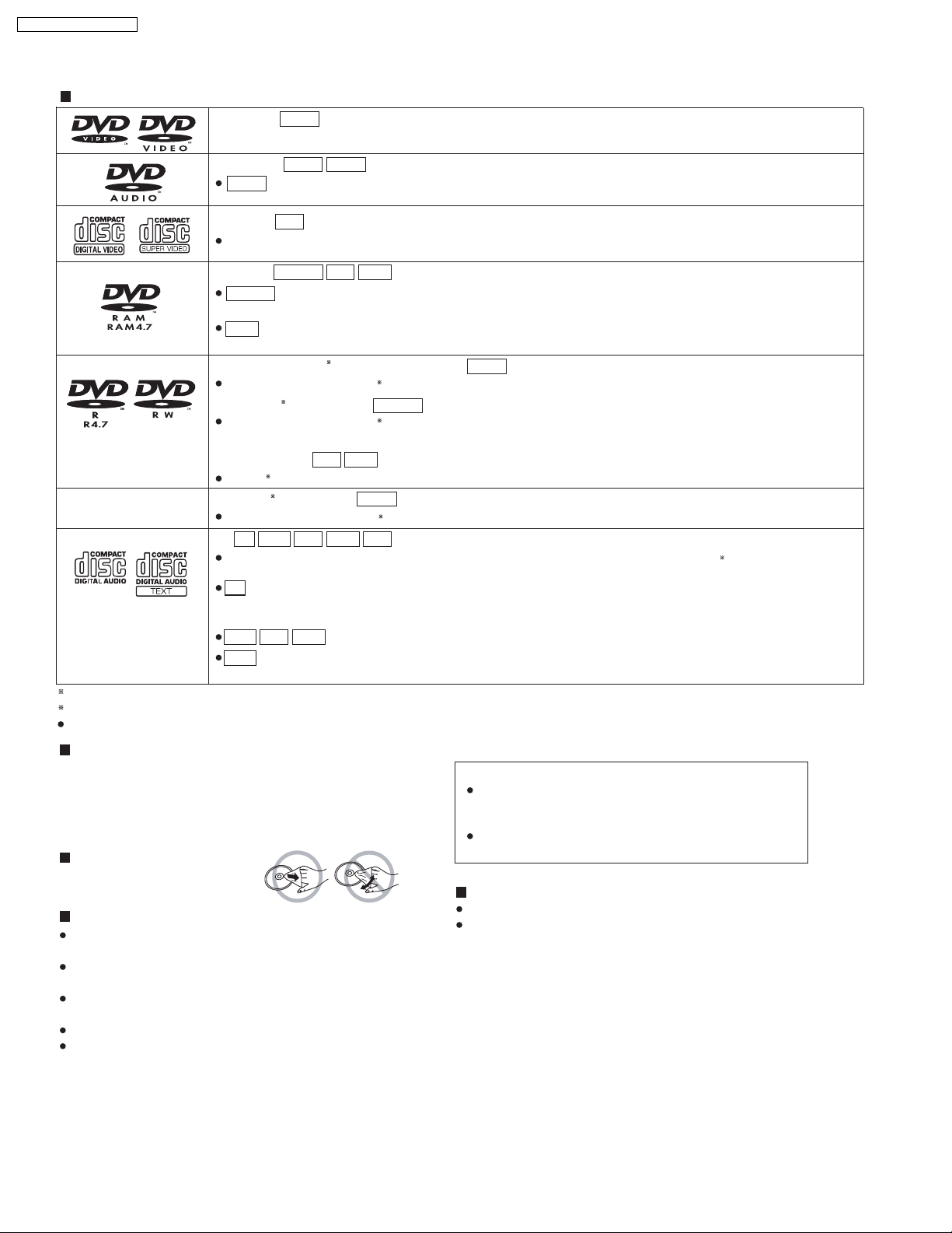
7.3. Disc information
Discs that can be played
DVD-Video
—
DVD-Audio
DVD-V
DVD-V
DVD-A
DVD-V
Some DVD-Audio discs contain DVD-Video content.
Video CD
VCD
Including SVCD (Conforming to IEC62107).
DVD-RAM
DVD-VR
DVD-VR
Recorded with devices using Version 1.1 of the Video Recording Format (a
standard), such as DVD video recorders, DVD video cameras, personal computers, etc.
JPEG
Recorded with Panasonic SD multi cameras or DVD video recorders using the
File System) Standard Version 1.0.
(DVD-Video) (DVD-Video)/
DVD-R
Discs recorded and finalized on DVD video recorders or DVD video cameras.
DVD-R (VR)
Discs reco
MP3
JPEG
unified video recording
DCF (Design rule for Camera
1
DVD-RW
2
1
DVD-RW
rded and finalized on DVD video recorders or DVD video cameras using Version 1.1 or 1.2 (DVD-R only)
(VR)/
DVD-VR
2
DVD-V
of the Video Recording Format (a unified video recording standard).
DVD-RCD/
DVD-RW
2
Finalize the disc after recording.
1
(Video) (Video)
—
+R +RW/
Discs recorded and finalized
CD
This unit can play CD-R/RW recorded with the above formats. Close the sessions or finalize
MP3
JPEG
DVD-V
2
on DVD video recorders or DVD video cameras.
JPEGMP3 VCDWMA
2
recording.
This unit is compatible with HDCD, but does not support the Peak Extend function (a function which expands the
CD
dynamic range of high-level signals).
HDCD-encoded CDs sound better because they are encoded with 20 bits, as compared with 16 bits for all other CDs.
JPEGMP3WMA
This unit also plays HighMAT discs.
WMA
This unit does not support Multiple Bit Rate (MBR: an encoding process for audio content that produces an
audio file encoded at several different bit rates).
1
Includes one-sided, double-layered discs.
2
A process that allows play on compatible equipment.
It may not be possible to play all the abovementioned discs in some cases due to the type of disc or condition of the recording.
the disc after
Discs that cannot be played
DVD-RW version 1.0, DVD-ROM, CD-ROM, CDV, CD-G, SACD ,
DivX Video Discs and Photo CD, DVD-RAM that cannot be removed
from their cartridge, 2.6-GB and 5.2-GB DVD-RAM, and “Chaoji
VCD” available on the market including CVD, DVCD and SVCD that
do not conform to IEC62107.
To clean discs
Wipe with a damp cloth and then wi pe
dry.
Disc handling precautions
Do not attach labels or stickers to discs. This may cause disc
warping, rendering it unusable.
Do not write on the label side with a ball-point pen or other writing
instrument.
Do not use record cleaning sprays, benzine, thinner, liquids which
prevent static electricity, or any other solvent.
Do not use scratch-proof protectors or covers.
Do not use the following discs:
– Discs with exposed adhesive from removed stickers or labels
(rented discs, etc).
– Discs that are badly warped or cracked.
– Irregularly shaped discs, such as heart shapes.
Note about using a DualDisc
The digital audio content side of a DualDisc does not meet
the technical specifications of the Compact Disc Digital Audio
(CD-DA) format so playback may not be possible.
Do not use DualDisc in this unit as it may not possible to
insert it correctly and it may get scratched or scraped.
Clean this unit with a soft, dry cloth.
Never use alcohol, paint thinner or benzine to clean this unit.
Before using chemically treated cloth, carefully read the instructions that
came with the cloth.
Do not use commercially available lens cleaners as they may
cause malfunction. Cleaning of the lens is generally not neccessary
although this depends on the operating environment.
Before moving the unit, ensure the disc trays are empty.
Failure to do so will risk severely damaging the disc and the unit.
14
SA-HT740P / SA-HT740 PC
15
SA-HT740P / SA-HT740 PC
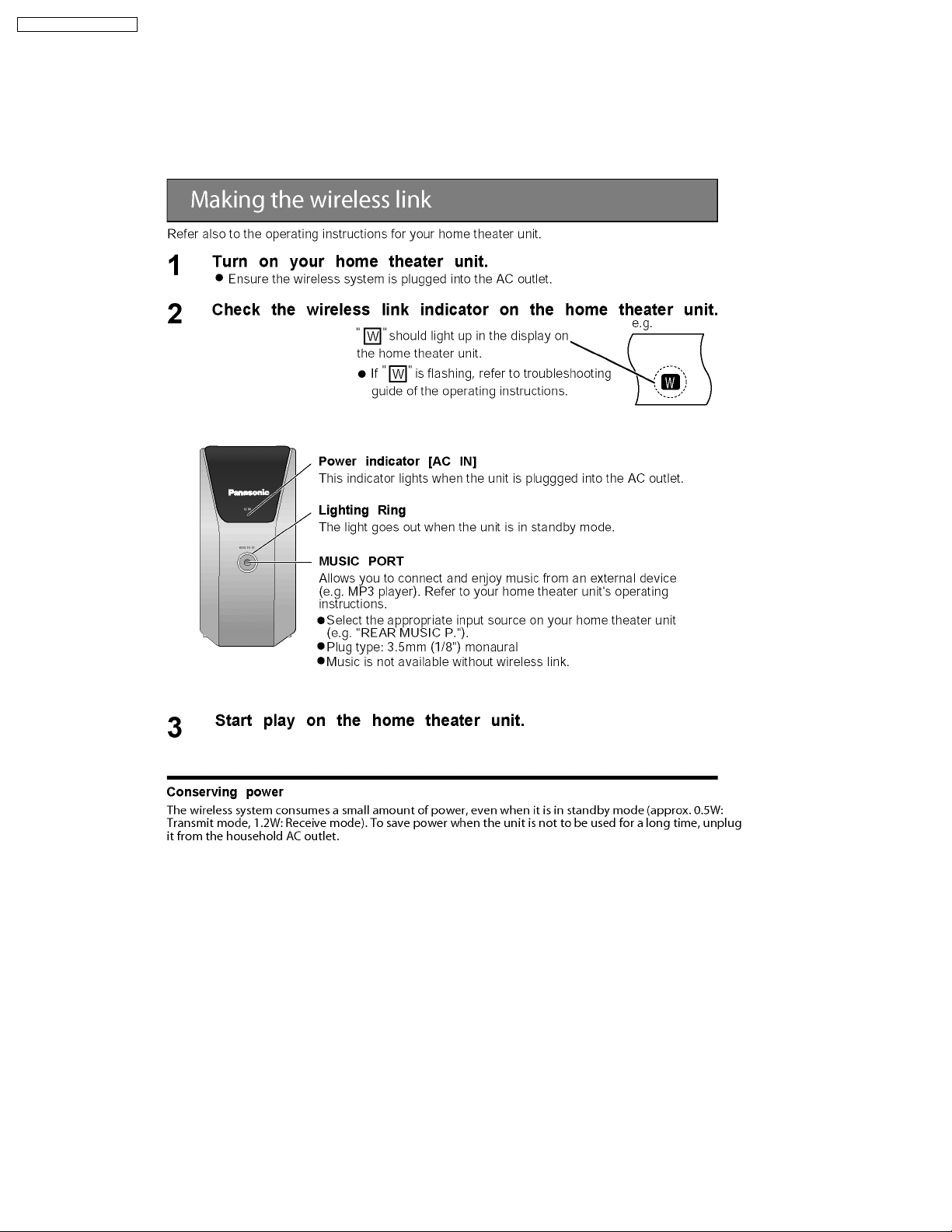
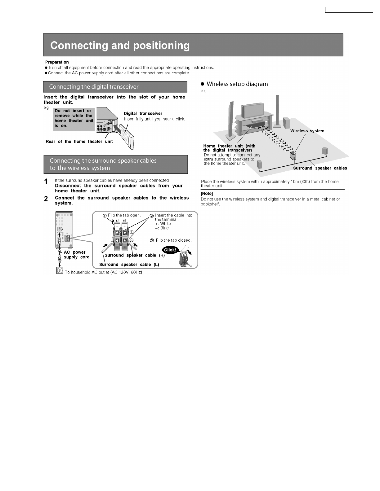
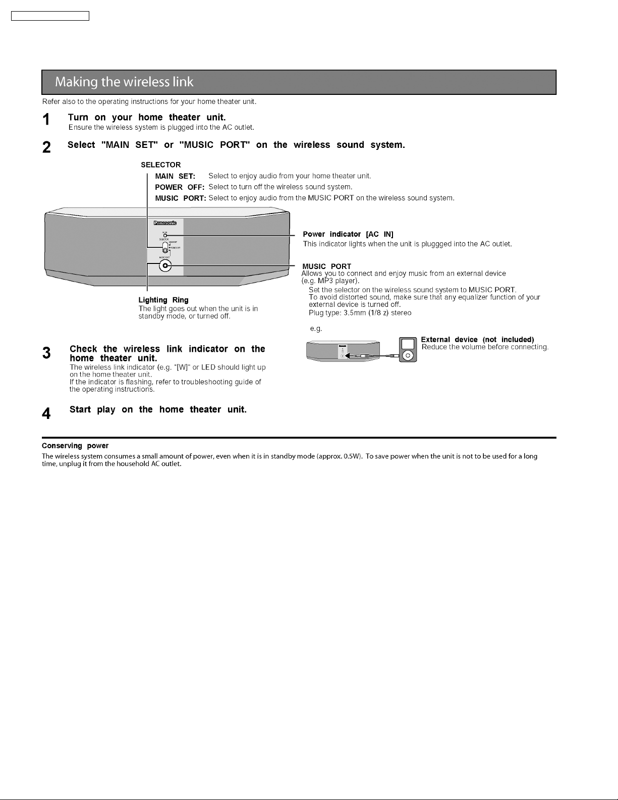
8 New Features
8.1. Using of Receiver Unit (SH-FX60 / SH-FX80)
· This model can be equipped with the digital transmitter and receiver to enjoy surround sound wirelessly.
8.1.1. Below is tips on using the digital receiver (SE-FX60)
16
8.1.2. Tips on using digital transmitter (SH-FX60T)
SA-HT740P / SA-HT740 PC
17
SA-HT740P / SA-HT740 PC
8.1.3. Below is tips on using digital receiver (SB-FX80)
18

8.1.4. Tips on using digital transmitter (SH-FX80T)
SA-HT740P / SA-HT740 PC
19
SA-HT740P / SA-HT740 PC
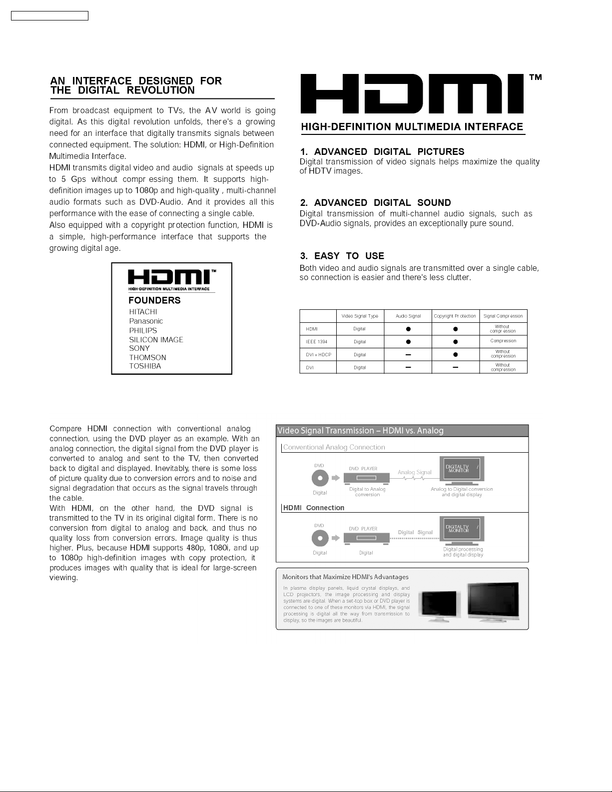
8.2. About HDMI
8.2.1. What is HDMI?
8.2.2. Advanced Digital Pictures
20
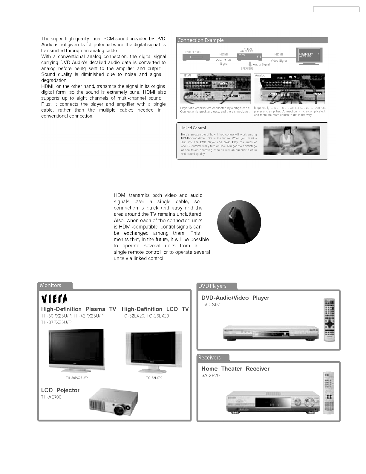
8.2.3. Advanced Digital Sound
SA-HT740P / SA-HT740 PC
8.2.4. Easy to Use
8.2.5. HDMI Compatible Products
21
SA-HT740P / SA-HT740 PC
9 Self-Diagnosis and special mode setting
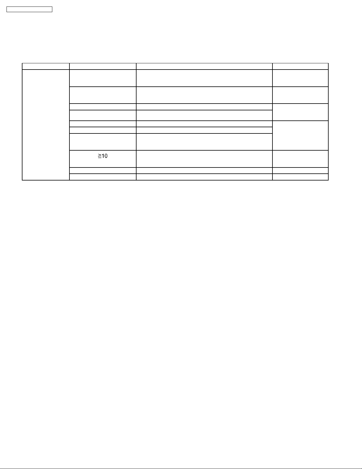
9.1. Service Mode Summary Table
The service modes can be activated by pressing various button combination on the player and remote control unit.
Below is the summary of major checking:
Player buttons Remote control unit buttons Application Note
STOP 0 Error code display (Refer to the section,
5 Jitter checking (Refer to the section
6 Region display and mode (Refer to the section “9.2
7 Micro-processor firmware version check
FUNCTIONS DVD laser drive current check (Refer to the item “9.2.1.
3 CD laser drive current check
PAUSE Writing of laser drive current value after replacement of optical
pickup (Do use this function only when optical pickup is
replaced.)
Initialization of the player (factory setting is restored.)
Used after replacement of micro-computer, FLASH ROM IC,
EEPROM and HDMI module.
8 DVD HDMI Module firmware version check
ENTER DVD Module Reset.
“9.3 DVD Self Diagnostic
Function-Error Code”).
“13.4 Optical
adjustment”).
Service Mode Table 1 for
more information”).
Optical Pick-up SelfDiagnosis”).
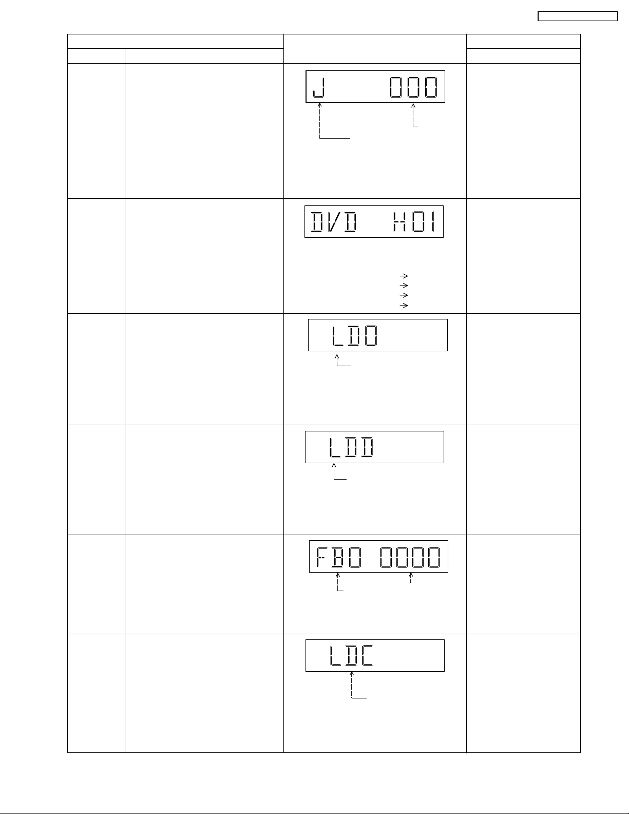
9.2. Service Mode Table 1
By pressing various button combin ations on the player and remote control unit can activate the various service modes for checking.
Special Note:
Due to the limitations of the no. characters that can be shown on FL Display, the “FL Display” button on the remote control unit
is used to show the following page. (Display 1 / Display 2).
22
SA-HT740P / SA-HT740 PC
Mode Name
Jitter check
Error code
check
Initial setting
of laser drive
current
Item
Description
Jitter check
Jitter rate is measured and displayed.
Measurement is repeatedly done in
the cycle of one second. Read error
counter starts from zero upon mode
setting. When target block data failed
to be read out, the counter advances
by one increment. When the failure is
caused by minor error, it may be
corrected when retried to enable
successful reading. In this case, the
counter advances by one. When the
error persists even after retry, the
counter may jump by two or more.
Error code check
The latest error code stored in the
EEPROM IC is displayed.
Initial setting of laser drive current.
Initial current value for each of DVD
laser and CD laser is separately saved
in the EEPROM IC.
FL Display
Jitter rate
Jitter check mode
Jitter rate is shown in decimal notation to
one place of decimal.
Focus drive value is shown in hexadecimal
notation.
Error code (play_err) is expressed in the
following convention.
Error code = 0 x DAXX is expressed: DVDnn UXX
Error code = 0 x DBXX is expressed: DVDnn HXX
Error code = 0 x DXXX is expressed: DVDnn FXXX
Error code = 0 x 0000 is expressed: DVDnn F--* "xx" denotes the error code
Laser current measurement
mode
The value denotes the current in decimal
notation. The above example shows the
initial current is 34mA and 28mA for DVD
laser and CD laser respectively when the
laser is switched on.
Key Operation
Front Key
In STOP (no disc) mode,
press STOP button on the
player, and "5" button on
the remote control unit.
Press STOP or OPEN
button to exit.
Press "FL Display" button on
remote control unit for next
page (FL Display).
In STOP (no disc) mode,
press STOP button on the
player, and "0" button on the
remote control unit. * With
pointing of cursor up and
down on display.
Cancelled automatically
5 seconds later.
To exit, press [POWER]
button on main unit or
remote control.
In STOP (no disc) mode,
press STOP button on the
player, and PAUSE button
on the remote control unit.
Cancelled automatically
5 seconds later.
Press "FL Display" button on
remote control unit for next
page (FL Display) on values
of laser drive current.
DVD laser
drive current
measurement
ADSC internal
RAM data
check
CD laser drive
current
measurement
DVD laser drive current measurement
·DVD laser drive current is measured
and the result is displayed together
with the initial value stored in the
EEPROM IC.
After the measurement, DVD laser
emission is kept on. It is turned off
when POWER key is switched off. (It
is also turned off when POWER button
on the player is switched off.)
ADSC internal RAM data check
·ADSC internal RAM data is read out
and displayed.
CD laser drive current measurement
CD laser drive current is measured
and the result is displayed together
with the initial value stored in the
EEPROM IC.
After the measurement, CD laser
emission is kept on. It is turned off
when POWER key is switched off. (It
is also turned off when POWER button
on the player is switched off.)
DVD laser current
measurement mode
The value denotes the current in decimal
notation.
The above example shows the initial current
is 34mA and the measured value is 32mA.
Address
RAM data for
specified address
The value is shown in hexadecimal
notation. The above example shows the
data in ADSC address OFAh is 6901h.
CD laser current
measurement mode
The value denotes the current in decimal
notation.
The above example shows the initial current
is 28mA and the measured value is 26mA.
In STOP (no disc) mode,
press STOP button on the
player, and FUNCTIONS
button on the remote
control unit.
Cancelled automatically
5 seconds later.
Press "FL Display" button on
remote control unit for next
page (FL Display) on values
of dvd drive current.
In STOP (no disc) mode,
press STOP button on the
player, and "1" button on
the remote control unit.
Press STOP or PLAY
button.
In STOP (no disc) mode,
press STOP button on the
player, and "3" button on
the remote control unit.
Cancelled automatically
5 seconds later.
Press "FL Display" button on
remote control unit for next
page (FL Display).
23
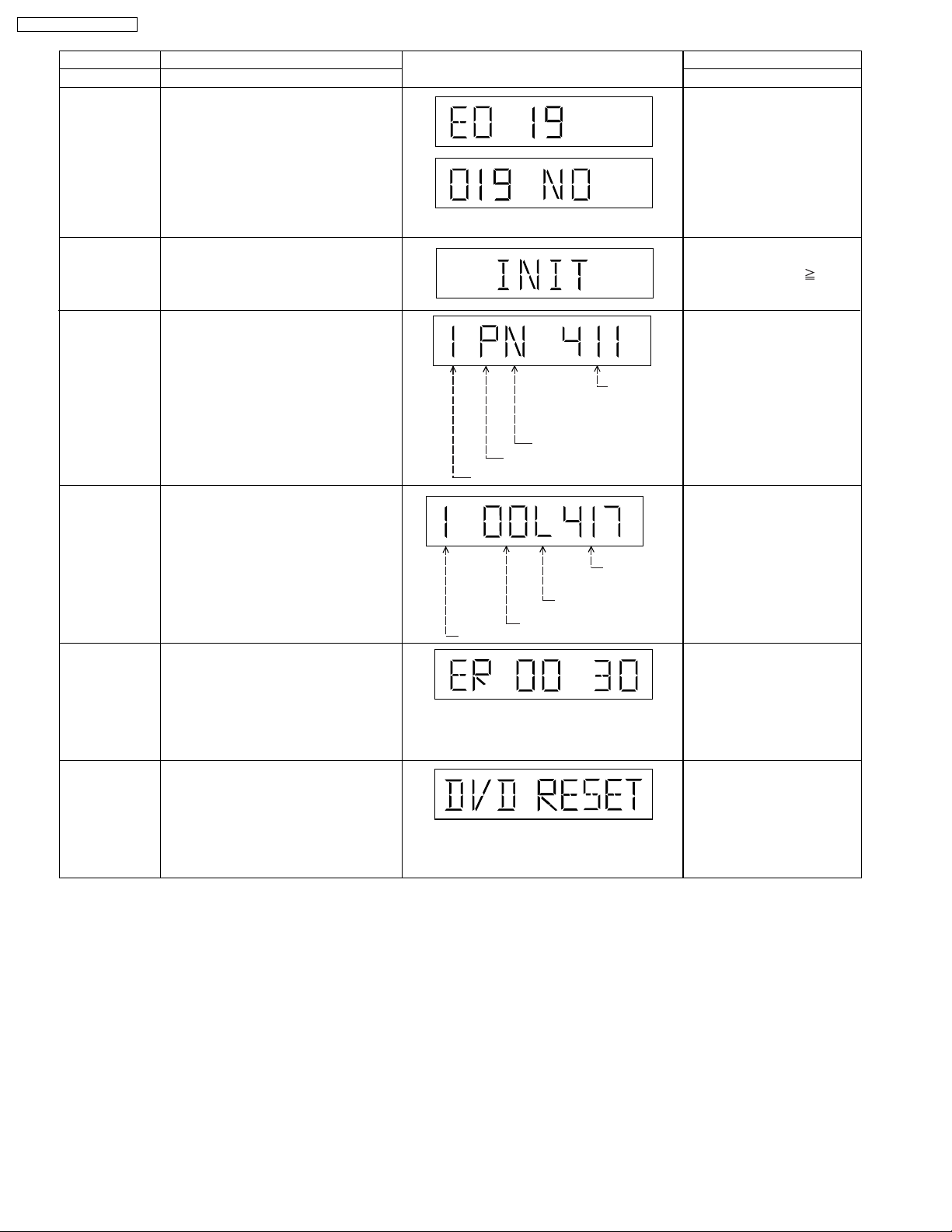
SA-HT740P / SA-HT740 PC
Micro-processor
firmware version
display &
EEPROM
checksum
display.
Initialization
Region display
DVD (HDMI)
module
firmware
version display
Communication
error display
Item
DescriptionMode Name
Micro-processor firmware version
display & EEPROM checksum display.
Initialization
User settings are cancelled and player
is initialized to factory setting.
Region display & mode
DVD (HDMI) module
firmware version display is on the
FL Display.
Displays frequency of communication
errors between system control IC and
mechanism control IC during DVD
module.
N: noPAL / P: PAL
Region No.
Region
FL Display
N: NTSC / 6: PAL60
Destination
System controller
generation
Panel
controller
jumper
information
System
controller
version
Key Operation
Front Key
In STOP (no disc)
mode, press STOP button
on the player, and "7"
button on the remote
control unit.
Cancelled automatically
5 seconds later.
Press "FL Display" button on
remote control unit for next
page. (FL Display)
In STOP (no disc)
mode, press STOP button
on the player , and
10
button on the remote
control unit.
In STOP (no disc)
mode, press STOP button
on the player, and "6"
button on the remote
control unit.
Cancelled automatically
5 seconds later.
In STOP (no disc)
mode, press STOP button
on the player, and "8"
button on the remote
control unit.
Cancelled automatically
5 seconds later.
In STOP (no disc)
mode, press STOP button
on the player, and "MENU"
button on the remote
control unit.
Cancelled automatically
5 seconds later.
DVD Module
Reset
To reset DVD Module.
In STOP (no disc)
mode, press STOP button
on the player, and
"ENTER" button on the
remote control unit.
Cancelled automatically
5 seconds later.
24

SA-HT740P / SA-HT740 PC
Mode Name
Timer 1 check
Timer 1 reset
Timer 2 check
Timer 2 reset
Item
Description
Timer 1 check
Laser operation timer Operation time is
measured separately for DVD laser
and CD laser.
Press "FL Display" button for next
page of FL Display
Timer 1 reset
Laser operation timer Operation time
of both DVD laser and CD laser is
reset all at once.
Timer 2 check
Spindle motor operation timer
Press "FL Display" button for next
page of FL Display
Timer 2 reset
Spindle motor operation timer
FL Display
Shown to the left is DVD laser time, and to
the right CD laser time.
Time is shown in 4 digits of decimal notation
in a unit of 10 hours.
"0000" will follow "9999".
T1–0000/0000 (display1/display2)
Time is shown in 5 digits of decimal notation in
a unit of 10 hours.
"00000" will follow "99999".
T2–00000
Key Operation
Front Key
In STOP (no disc)
mode, press STOP button
on the player, and " "
button on the remote
control unit.
Cancelled automatically
5 seconds later.
While displaying Timer 1
data, press STOP button
on the player, and " "
button on the remote
control unit.
Cancelled automatically
5 seconds later.
In STOP (no disc)
mode, press STOP button
on the player, and " "
button on the remote
control unit.
Cancelled automatically
5 seconds later.
While displaying Timer 2
data, press STOP button on
the player, and " " button
on the remote control unit.
Cancelled automatically
5 seconds later.
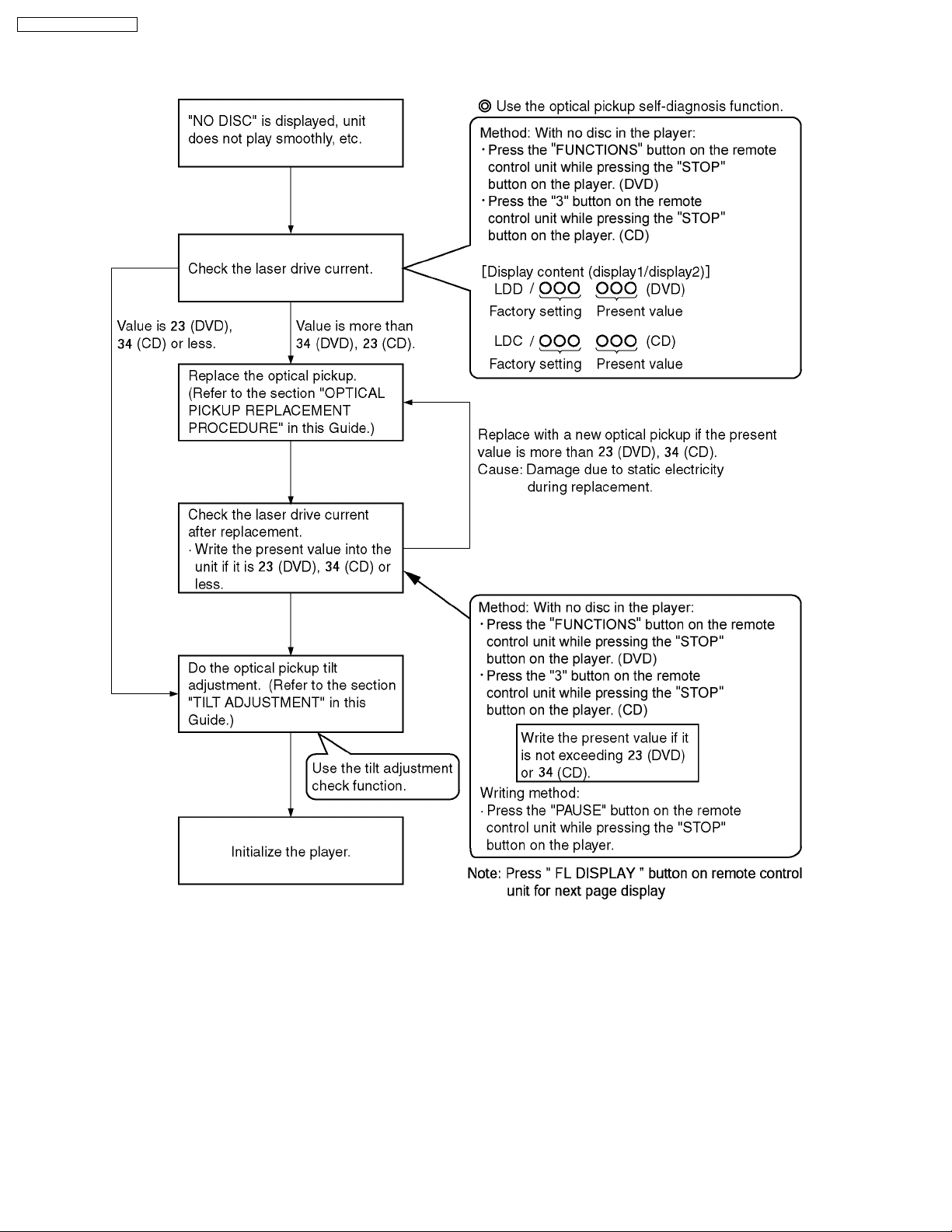
9.2.1. Optical Pick-up Self-Diagnosis
The optical pickup self-diagnosis function and tilt adjustment check function have been included in this unit. When repairing, use
the following procedure for effective self-diagnosis and tilt adjustment. Be sure to use the self-diagnosis function before replacing
the optical pickup when "NO DISC" is displayed. As a guideline, you should replace the optical pickup when the value of the laser
drive current is more than 10 (Difference between actual and preset value).
Note:
Press the power button to turn on the power, and check the value within three minutes before the unit warms up. (Otherwise,
the result will be incorrect.)
25
SA-HT740P / SA-HT740 PC
26
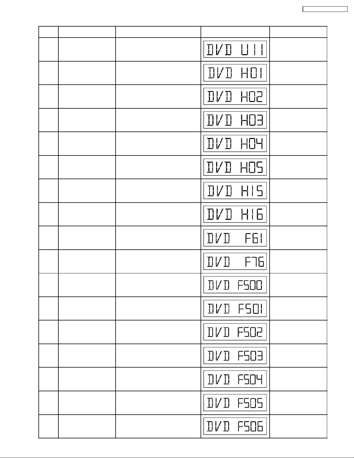
9.3. DVD Self Diagnostic Function-Error Code
SA-HT740P / SA-HT740 PC
Error
Code
U11 Focus servo error Focus coil NG (OPU unit abnormal) Press [ n STOP] on main
H01 Tray loading error /
H02 Spindle servo error, DSC
H03 Traverse motor error (Traverse motor, IC8251) Press [ n STOP] on main
H04 Tracking servo error Tracking coil NG (OPU unit abmormal) Press [ n STOP] on main
H05 Seek timeout error Timeout of unit when seeking time is
H15 Disc tray open detection
Diagnosis Contents Description of error Automatic FL Display Remarks
unit for next error.
abnormality
disc motor error
switch (S9001) failure
The tray is not able to open Press [ n STOP] on main
(Spindle servo, DSC (IC8251) Spindle
motor, CLV servo error)
reached
The disc tray cannot be opened: it closes
spontaneously
unit for next error
Press [ n STOP] on main
unit for next error
unit for next error
unit for next error
Press [ n STOP] on main
unit for next error
Press [ n STOP] on main
unit for next error
H16 Disc tray close detection
switch (S9001) failure
F61 Power digital amp IC op &
DC output voltage
abnormal.
F76 Power digital amp IC op &
DC output voltage
abnormal.
F500 DSC error DSC (IC8251) stops in the occurrence of
F501 DSC not Ready error DSC-system computer communication
F502 DSC Time out error Similar as F500 Press [ n STOP] on main
F503 DSC communication
Failure
F504 Abnormal adjusting DSC
data slice offset
The disc tray cannot be closed: it opens
spontaneously
Upon power-on PCONT=High,
DCDET=Low
Speaker Jack shorted or amp circuit Press [ n STOP] on main
servo error (startup, focus error, etc.)
error (Communication failure caused by
idling of DSC)
Communication error (result error
occurred although communication
command was sent)
Press [ n STOP] on main
unit for next error
Press [ n STOP] on main
unit for next error
unit for next error
Press [ n STOP] on main
unit for next error
Press [ n STOP] on main
unit for next error
unit for next error
Press [ n STOP] on main
unit for next error
Press [ n STOP] on main
unit for next error
F505 DSC Attention error Similar as F500 Press [ n STOP] on main
F506 Invalid media Disc is flipped over, TOC unreadable,
incompatible disc media
unit for next error
Press [ n STOP] on main
unit for next error
27
SA-HT740P / SA-HT740 PC
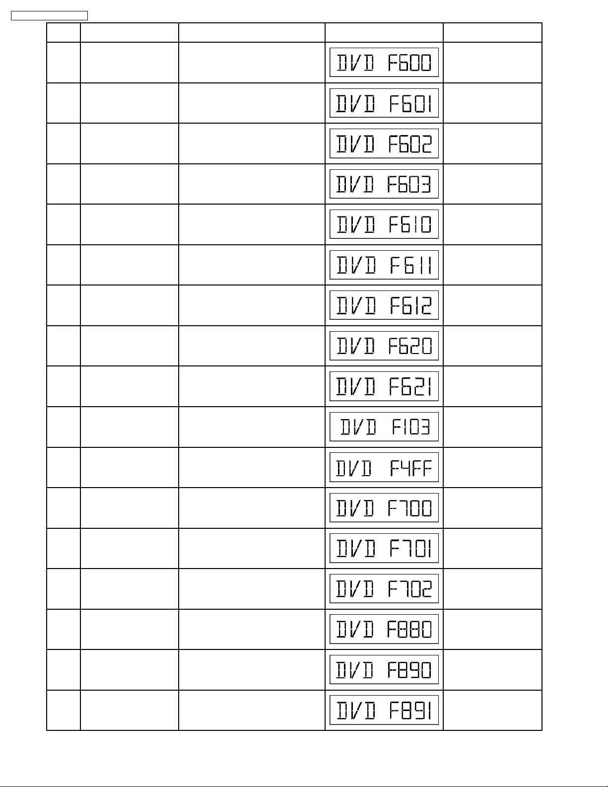
Error
Code
F600 Access failure to
F601 Indeterminate sector ID
Diagnosis Contents Description of error Automatic FL Display Remarks
management information
caused by demodulation
Operation stopped because navigation
data is not accessible caused by the
demodulation defect
Press [ n STOP] on main
unit for next error
error
requested
Operation stopped caused by the
request to access abnormal ID data
Press [ n STOP] on main
unit for next error
F602 Access failure to LEAD-IN
caused by demodulation
LEAD IN data unreadable Press [ n STOP] on main
unit for next error
error
F603 Access failure to KEYDET
caused by demodulation
Access failure to CSS data of disc Press [ n STOP] on main
unit for next error
error
F610 ODC abnormality No permission for command execution Press [ n STOP] on main
unit for next error
F611 No CRC OK for a specific
time (CD)
F612 No CRC OK for a specific
time (DVD)
F620 Laser safeguard: high
temperature condition
F621 Laser safeguard: circuit
failure condition
F103 Illegal highlight Position Big possibility of disc specification
Access failure to seek address in CD
series
Press [ n STOP] on main
unit for next error
Access failure to ID data in DVD series Press [ n STOP] on main
unit for next error
High temperature of the laser guide unit
(OPU unit)
Circuitry failure of the laser guide unit
(OPU unit)
Press [ n STOP] on main
unit for next error
Press [ n STOP] on main
unit for next error
Press [ n STOP] on main
violation during highlight display
unit for next error
F4FF Force initialize failure (time
out)
Timeout when force initialization fails Press [ n STOP] on main
unit for next error
F700 MBX overflow When replying message to disc manager Press [ n STOP] on main
unit for next error
F701 Message command does
not end
F702 Message command
changes
F880 Task number is not
appropriate
F890 Sending message when
message is being sent to
Next message is sent before replying to
disc manager
Message is changed before it is sent as
a reply to disc manager
Message coming from a non-existing
task
Press [ n STOP] on main
unit for next error
Press [ n STOP] on main
unit for next error
Press [ n STOP] on main
unit for next error
Sending message to AV task Press [ n STOP] on main
unit for next error
AV task
F891 Message couldn’t be sent
to AV task
Begin sending message to AV task Press [ n STOP] on main
unit for next error
28
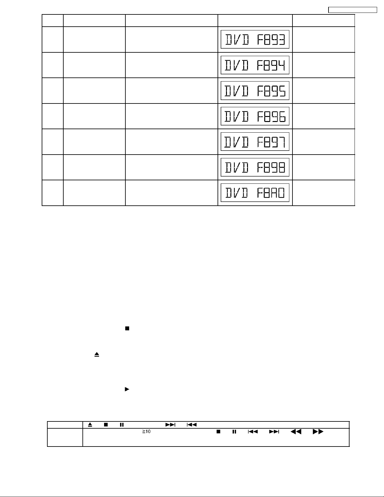
Error
Code
F893 FLASH ROM IC problem FLASH ROM IC installed is not operating
Diagnosis Contents Description of error Automatic FL Display Remarks
properly (Neccessary replacement of
FLASH ROM IC) or firmware problem
SA-HT740P / SA-HT740 PC
Press [ n STOP] on main
unit for next error
F894 EEPROM abnormality EEPROM IC installed is not operating in
F895 Region setting abnormality Firm version agreement check for factory
F896 No existence model Firm version agreement check for factory
F897 Initialize is not completed Initialize completion check for factory
F898 Disagreement of hardware
and software
F8A0 Message command is not
appropriate
normal condition (EEPROM contains
neccessary data)
preset setting failure prevention. Check
region setting & re-initialize
preset setting failure prevention
preset setting failure prevention
Unsuitable combination of AV
DECORDER, SDRAM and FLASH ROM
(firmware)
Begin sending message to AV task Press [ n STOP] on main
Press [ n STOP] on main
unit for next error
Press [ n STOP] on main
unit for next error
Press [ n STOP] on main
unit for next error
Press [ n STOP] on main
unit for next error
Press [ n STOP] on main
unit for next error
unit for next error
Note:
An error code will be canceled if a power supply is turned OFF.
*1: CPPM is the copy guard function beforehand written in the disk for protection of copyrights.
*2: CEC is the consumer electronic control used for high-level user control of HDMI-connected devices.
*3: HDCP is the specification developed to control digital audio & video contents transmission for DVI or HDMI connections.
9.4. Sales Demonstration Lock Function
This function prevents discs from being lost when the unit is used for sales demonstrations by disabling the disc eject function.
"LOCKED" is displayed on the unit, and ordinary operation is disabled.
9.4.1. Setting
· Prohibiting removal of disc
1. Select the DVD/CD function.
2. Press and hold down the
“___LOCKED_” appears when the function is activated.)
Note:
OPEN/CLOSE
, DISC CHECK and DISC CHANGE buttons are invalid and the player displays “___LOCKED_” while
the lock function mode is entered.
· Prohibiting operation of selector and disk
1. Select the DVD/CD function.
2. Press and hold down the
“___LOCKED_” appears when the function is activated.)
Note:
The following buttons are invalid and the player displays “___LOCKED_” while the lock function mode is entered.
Player , , , SELECTOR, , , VOLUME KNOB, DISC CHECK, DISC CHANGE, DISC1-DISC5
Remote
controller unit
SLEEP, REPEAT, 0~9, , RETURN, TOP MENU, , , , , , ,
POSITION MEMORY, TUNER/BAND, D.MIX, CH SELECT/ TEST, SET UP/ MUTING, DISPLAY, GROUP, TV, VCR/
AUX, QUICK REPLAY, SUBTITLE, FL DISPLAY, CH & VOLUME
button and the power button on the player for at least three seconds. (The message,
button and the power button on the player for at least three seconds. (The message,
9.4.2. Cancellation
The lock can be cancelled by the same procedure as used in setting. ("UNLOCK" is displayed on cancellation. Disconnecting the
29

SA-HT740P / SA-HT740 PC
power cable from power outlet does not cancel the lock.)
9.5. Service Precautions
9.5.1. Recovery after the DVD player is repaired
· W hen the IC or HDMI module P.C.B. is replaced, carry out the recovery processing to optimize the drive.
Playback the recovery disk to process the recovery automatically.
· Recovery disc (Product number: RFKZD03R005)
· Performing recovery process
1. Load the recovery disc RFKZD03R005 on to the player and run it.
2. Recovery is performed automatically. When it is finished, a message appears on the screen.
3. Remove the recovery disc.
4. Turn off the power.
5. Initialize the player.
9.5.2. Firmware version-up of the DVD player
· The firmware of the DVD player may be renewed to improve the quality including operability and playability to the substandard
discs.processing to optimize the drive.
The recovery disc has also firmware version-up.
· After version-up, recovery processing is executed automatically.
· Part number of the recovery disc for version-up will be noticed when it is supplie d.
· Updating firmware
1. Load the recovery disc on to the player and run it.
2. Firmware version of the player is automatically checked. Appropriate message appears whenever necessary.
3. Using remote controller´s cursor key, select whether version updating is to be done or not. (Selection of Yes/No)
4. a. If Yes is selected, version updating is performed.
b. If No is selected, only recovery is performed.
5. a. When updating is finished, remove the disc according to the message appearing on the screen.
b. Remove the disc according to the message appearing on the screen.
6. Turn off the power.
Note:
If the AC power supply is shut out during version-up due to a power failure, the version-up is improperly carried out.
In such a case, replace the FLASH ROM IC and carry out the version-up again.
9.5.3. DVD Module Reset
· W hen after replacing Flash Rom IC or the DVD Module P.C.B., FL displays error code “ DVD F897”. This means the unit is not
initialized properly and the following process needs to be carry out.
· Procedures:
1. Press
2. FL display show “ Initialize”
3. While still pressing “STOP” button on main unit, press “ENTER” on remote control.
4. FL will display “DVD RESET” before FL display will change to TOC reading again.
5. Power off unit. Unplug the AC cord.
6. Power on the unit. It should be no problem. If problem persist check on the DVD module P.C.B. or FLASH ROM IC.
on remote control while pressing “STOP” button on main unit.
30
 Loading...