

Page 1
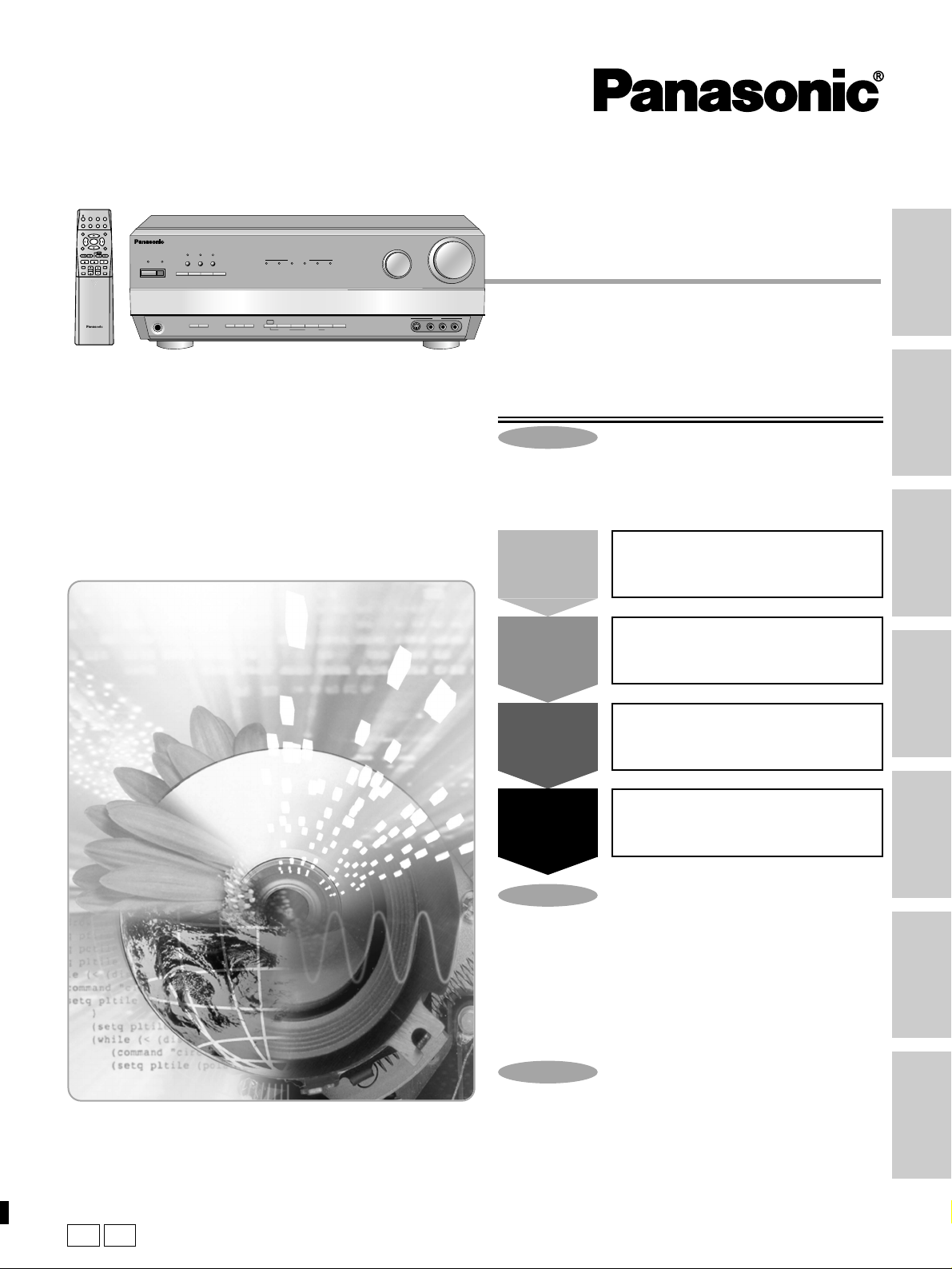
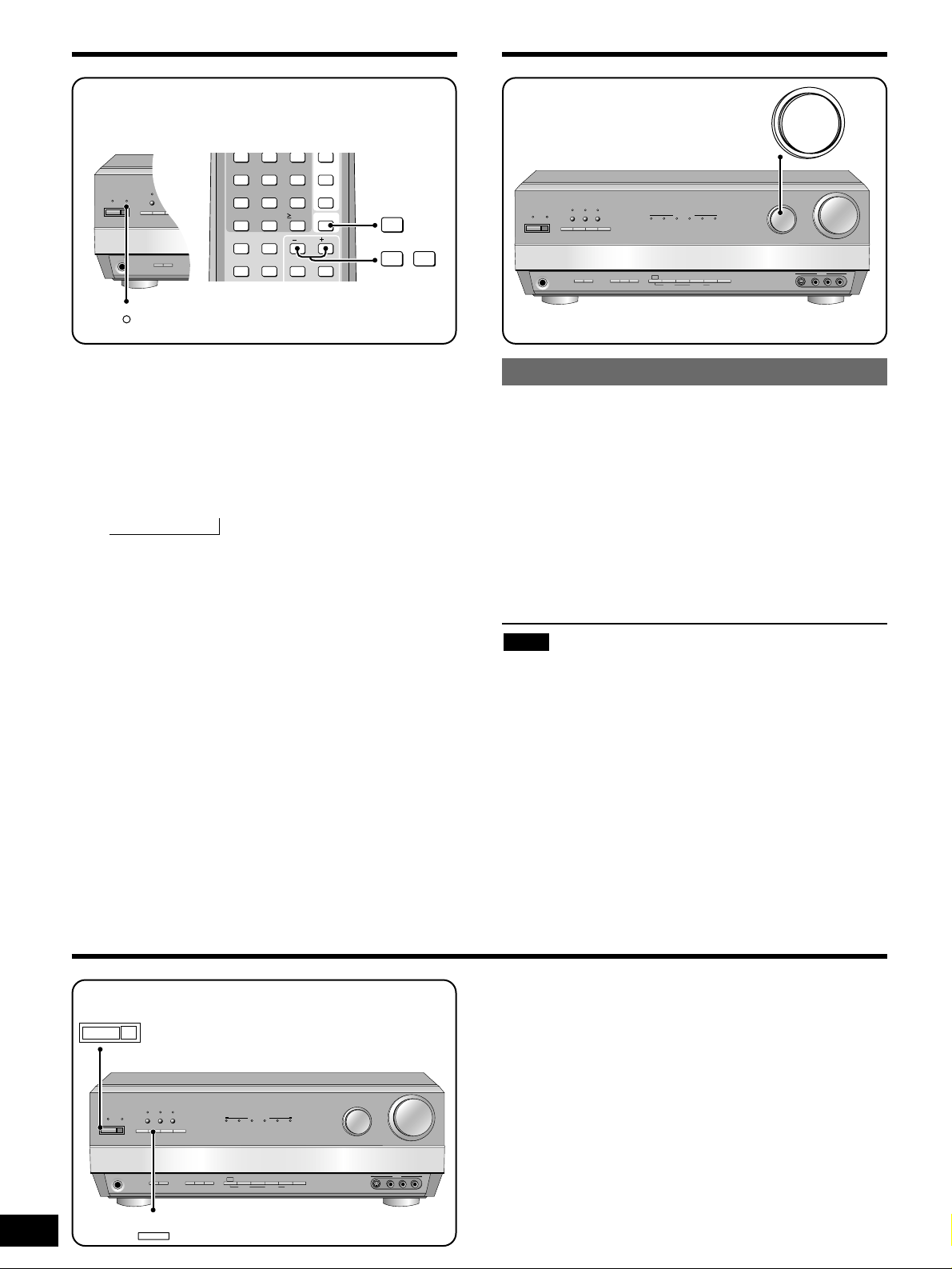
AV Control Receiver
Operating Instructions
Model No. SA-HE200
Dear customer
Thank you for purchasing this product.
Before connecting, operating or adjusting this product, please read
these instructions completely.
Please keep this manual for future reference.
Note:
“EB” on the packaging indicates the United Kingdom.
E EB
DISPLAY
Table of contents
Caution for AC Mains Lead ...............................................2
Safety precautions
.....................................................................2
Supplied accessories
................................................................4
The remote control
....................................................................4
Troubleshooting guide
...........................................................23
Specifications
..........................................................Back cover
Maintenance
.............................................................Back cover
Equipment connections
4
Speaker connections
8
Settings
10
Step 1
Control guide
12
Before use
Reference
Step 1
Step 2
Step 3
Step 4
Before use
Others
Reference
Step 2
Step 3
Step 4
Sound modes............................................................................16
Other functions
.........................................................................18
The radio
.....................................................................................19
RDS broadcasts ...............................................................20
Other settings
...........................................................................21
Timer function ..................................................................22
Making a recording
..................................................................22
The RESET function
................................................................22
Others
RQT6252-B
SOUND MODE
SUBWOOFER
TV
VCR
DVD
MD
TUNER/BAND
TAPE CD
RECEIVER
TOP MENU
MENU
ENTER
RETURN
SLOW /SEARCH
SKIP
PAUSESTOP
PLAY
^
CHANNEL VOLUME
MUTING
INPUT
SELECTOR
WAKE
8
RE-MASTER
SOURCE DIRECT
SOUND MODE
SOUND MODE
DSP
ENHANCED
HQ
SURROUND
DOLBY
NEO:6
PRO LOGIC 2
DIGITAL EX
MULTI DECODER
DOLBY
DOLBY
DTS-ESDOLBY
DTS
NEO:6
PRO LOGIC 2
DIGITAL
INPUT SELECTOR
VOLUME
DOWN UP
PHONES
A SPEAKERS B
TAPE
INPUT
DVD
- BAND
RDS
MODE
MONITOR
6CH INPUT
MEMORY
PRESET2 TUNING
PTY SEARCH PTY SELECTOR
1
FM MODE
–
DISPLAY
MODE
S-VIDEO IN VIDEO IN
VCR 3
L AUDIO IN R
Page 2
2
RQT6252
Fuse cover
Figure A
Figure B
Fuse
(5 ampere)
Fuse
(5 ampere)
Figure A
Figure B
Safety precautions
Placement
Set the unit up on an even surface away from direct sunlight, high
temperatures, high humidity, and excessive vibration. These
conditions can damage the cabinet and other components, thereby
shortening the unit’s service life.
Do not place heavy items on the unit.
Voltage
Do not use high voltage power sources. This can overload the unit
and cause a fire.
Do not use a DC power source. Check the source carefully when
setting the unit up on a ship or other place where DC is used.
AC mains lead protection
Ensure the AC mains lead is connected correctly and not damaged.
Poor connection and lead damage can cause fire or electric shock.
Do not pull, bend, or place heavy items on the lead.
Grasp the plug firmly when unplugging the lead. Pulling the AC
mains lead can cause electric shock.
Do not handle the plug with wet hands. This can cause electric
shock.
Foreign matter
Do not let metal objects fall inside the unit. This can cause electric
shock or malfunction.
Do not let liquids get into the unit. This can cause electric shock or
malfunction. If this occurs, immediately disconnect the unit from the
power supply and contact your dealer.
Do not spray insecticides onto or into the unit. They contain
flammable gases which can ignite if sprayed into the unit.
Service
Do not attempt to repair this unit by yourself. If sound is interrupted,
indicators fail to light, smoke appears, or any other problem that is
not covered in these instructions occurs, disconnect the AC mains
lead and contact your dealer or an authorized service center.
Electric shock or damage to the unit can occur if the unit is repaired,
disassembled or reconstructed by unqualified persons.
Extend operating life by disconnecting the unit from the power
source if it is not to be used for a long time.
(For United Kingdom)
(“EB” area code model only)
For your safety, please read the following text carefully.
This appliance is supplied with a moulded three pin mains plug for
your safety and convenience.
A 5-ampere fuse is fitted in this plug.
Should the fuse need to be replaced please ensure that the
replacement fuse has a rating of 5-ampere and that it is approved
by ASTA or BSI to BS1362.
Check for the ASTA mark or the BSI mark on the body of the fuse.
If the plug contains a removable fuse cover you must ensure that it
is refitted when the fuse is replaced.
If you lose the fuse cover the plug must not be used until a
replacement cover is obtained.
A replacement fuse cover can be purchased from your local dealer.
CAUTION!
IF THE FITTED MOULDED PLUG IS UNSUITABLE FOR
THE SOCKET OUTLET IN YOUR HOME THEN THE
FUSE SHOULD BE REMOVED AND THE PLUG CUT
OFF AND DISPOSED OF SAFELY.
THERE IS A DANGER OF SEVERE ELECTRICAL
SHOCK IF THE CUT OFF PLUG IS INSERTED INTO
ANY 13-AMPERE SOCKET.
If a new plug is to be fitted please observe the wiring code as stated
below.
If in any doubt please consult a qualified electrician.
IMPORTANT
The wires in this mains lead are coloured in accordance with the
following code:
Blue: Neutral, Brown: Live.
As these colours may not correspond with the coloured markings
identifying the terminals in your plug, proceed as follows:
The wire which is coloured Blue must be connected to the terminal
which is marked with the letter N or coloured Black or Blue.
The wire which is coloured Brown must be connected to the
terminal which is marked with the letter L or coloured Brown or Red.
WARNING: DO NOT CONNECT EITHER WIRE TO THE
EARTH TERMINAL WHICH IS MARKED WITH THE
LETTER E, BY THE EARTH SYMBOL OR
COLOURED GREEN OR GREEN/YELLOW.
THIS PLUG IS NOT WATERPROOF–KEEP DRY.
Before use
Remove the connector cover.
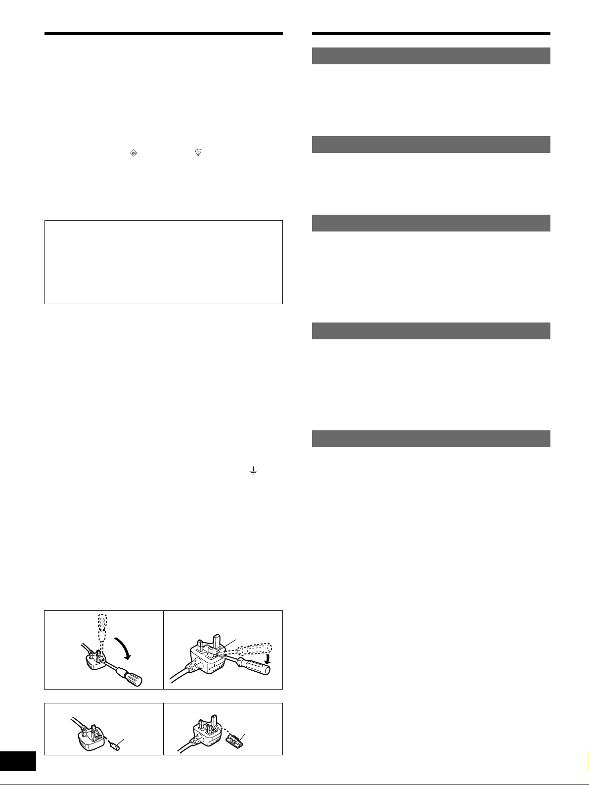
How to replace the fuse
The location of the fuse differ according to the type of AC mains
plug (figures A and B). Confirm the AC mains plug fitted and follow
the instructions below.
Illustrations may differ from actual AC mains plug.
1. Open the fuse cover with a screwdriver.
2. Replace the fuse and close or attach the fuse cover.
Caution for AC Mains Lead
Page 3
3
RQT6252
Step 1
Step 2
Step 3
Step 4
Before use
Others
Reference
CAUTION!
¡DO NOT INSTALL, OR PLACE THIS UNIT, IN A
BOOKCASE, BUILT-IN CABINET OR IN ANOTHER
CONFINED SPACE. ENSURE THE UNIT IS WELL
VENTILATED. TO PREVENT RISK OF ELECTRIC SHOCK
OR FIRE HAZARD DUE TO OVERHEATING, ENSURE
THAT CURTAINS AND ANY OTHER MATERIALS DO NOT
OBSTRUCT THE VENTILATION VENTS.
¡DO NOT OBSTRUCT THE UNIT’S VENTILATION
OPENINGS WITH NEWSPAPERS, TABLECLOTHS,
CURTAINS, AND SIMILAR ITEMS.
¡DO NOT PLACE SOURCES OF NAKED FLAMES, SUCH
AS LIGHTED CANDLES, ON THE UNIT.
¡DISPOSE OF BATTERIES IN AN ENVIRONMENTALLY
FRIENDLY MANNER.
WARNING:
TO REDUCE THE RISK OF FIRE, ELECTRIC SHOCK OR
PRODUCT DAMAGE, DO NOT EXPOSE THIS APPARATUS
TO RAIN, MOISTURE, DRIPPING OR SPLASHING AND
THAT NO OBJECTS FILLED WITH LIQUIDS, SUCH AS
VASES, SHALL BE PLACED ON THE APPARATUS.
VAROITUS!
¡ÄLÄ ASENNA TAI LAITA TÄTÄ LAITETTA
KABINETTITYYPPISEEN KIRJAKAAPPIIN TAI MUUHUN
SULJETTUUN TILAAN, JOTTA TUULETUS ONNISTUISI.
VARMISTA, ETTÄ VERHO TAI MIKÄÄN MUU MATERIAALI
EI HUONONNA TUULETUSTA, JOTTA VÄLTETTÄISIIN
YLIKUUMENEMISESTA JOHTUVA SÄHKÖISKU- TAI
TULIPALOVAARA.
¡¡
ÄLÄ PEITÄ LAITTEEN TUULETUSAUKKOJA
SANOMALEHDELLÄ, PÖYTÄLIINALLA, VERHOLLA TAI
MUULLA VASTAAVALLA ESINEELLÄ.
¡¡
ÄLÄ ASETA PALAVAA KYNTTILÄÄ TAI MUUTA
AVOTULEN LÄHDETTÄ LAITTEEN PÄÄLLE.
¡¡
HÄVITÄ PARISTOT LUONTOA
VAHINGOITTAMATTOMALLA TAVALLA.
SUOMI
VAROITUS:
TULIPALO-, SÄHKÖISKUVAARAN TAI TUOTETTA
KOHTAAVAN MUUN VAHINGON VÄHENTÄMISEKSI EI
LAITETTA SAA ALTISTAA SATEELLE, KOSTEUDELLE,
VESIPISAROILLE TAI ROISKEELLE, EIKÄ NESTETTÄ
SISÄLTÄVIÄ ESINEITÄ, KUTEN ESIMERKIKSI
MALJAKOITA, SAA ASETTAA LAITTEEN PÄÄLLE.
ADVARSEL!
¡¡
APPARATET MÅ IKKE PLASSERES I EN BOKHYLLE, ET
INNEBYGGET KABINETT ELLER ET ANNET LUKKET
STED HVOR VENTILASJONSFORHOLDENE ER
UTILSTREKKELIGE. SØRG FOR AT GARDINER ELLER
LIGNENDE IKKE FORVERRER
VENTILASJONSFORHOLDENE, SÅ RISIKO FOR
ELEKTRISK SJOKK ELLER BRANN FORÅRSAKET AV
OVERHETING UNNGÅS.
¡¡
APPARATETS VENTILASJONSÅPNINGER MÅ IKKE
DEKKES TIL MED AVISER, BORDDUKER, GARDINER OG
LIGNENDE.
¡¡
PLASSER IKKE ÅPEN ILD, SLIK SOM LEVENDE LYS,
OPPÅ APPARATET.
¡¡
BRUKTE BATTERIER MÅ KASSERES UTEN FARE FOR
MILJØET.
NORSK
ADVARSEL:
FOR Å REDUSERE FAREN FOR BRANN, ELEKTRISK STØT
ELLER SKADER PÅ PRODUKTET, MÅ DETTE APPARATET
IKKE UTSETTES FOR REGN, FUKTIGHET, VANNDRÅPER
ELLER VANNSPRUT. DET MÅ HELLER IKKE PLASSERES
GJENSTANDER FYLT MED VANN, SLIK SOM
BLOMSTERVASER, OPPÅ APPARATET.
THIS UNIT IS INTENDED FOR USE IN MODERATE
CLIMATES.
TÄMÄ LAITE ON TARKOITETTU KÄYTETTÄVÄKSI
LEUDOSSA ILMASTOSSA.
DETTE APPARATET ER BEREGNET TIL BRUK UNDER
MODERATE KLIMAFORHOLD.
This product may receive radio interference caused by mobile
telephones during use. If such interference is apparent, please
increase separation between the product and the mobile
telephone.
CAUTION
Do not place anything on top of this unit or block the heat
radiation vents in any way. In particular, do not place tape decks
or CD/DVD players on this unit as heat radiated from it can
damage your software.
www.panasonic.co.uk (for UK customers only)
¡Order accessory and consumable items for your product
with ease and confidence by telephoning our
Customer Care Centre Mon-Friday 9:00am-5:30pm.
(Excluding public holidays.)
¡Or go on line through our Internet Accessory ordering
application.
¡Most major credit and debit cards accepted.
¡All enquiries transactions and distribution facilities are
provided directly by Panasonic UK Ltd.
¡It couldn’t be simpler!
Customer Care Centre
For UK customers: 08705 357357
For Republic of Ireland customers: 01 289 8333
Technical Support
For UK customers: 0870 1 505610
This Technical Support Hot Line number is for Panasonic
PC software related products only.
For Republic of Ireland, please use the Customer Care
Centre number listed above for all enquiries.
For all other product related enquiries, please use the
Customer Care Centre numbers listed above.
For the United Kingdom and Republic of Ireland
Page 4
4
RQT6252
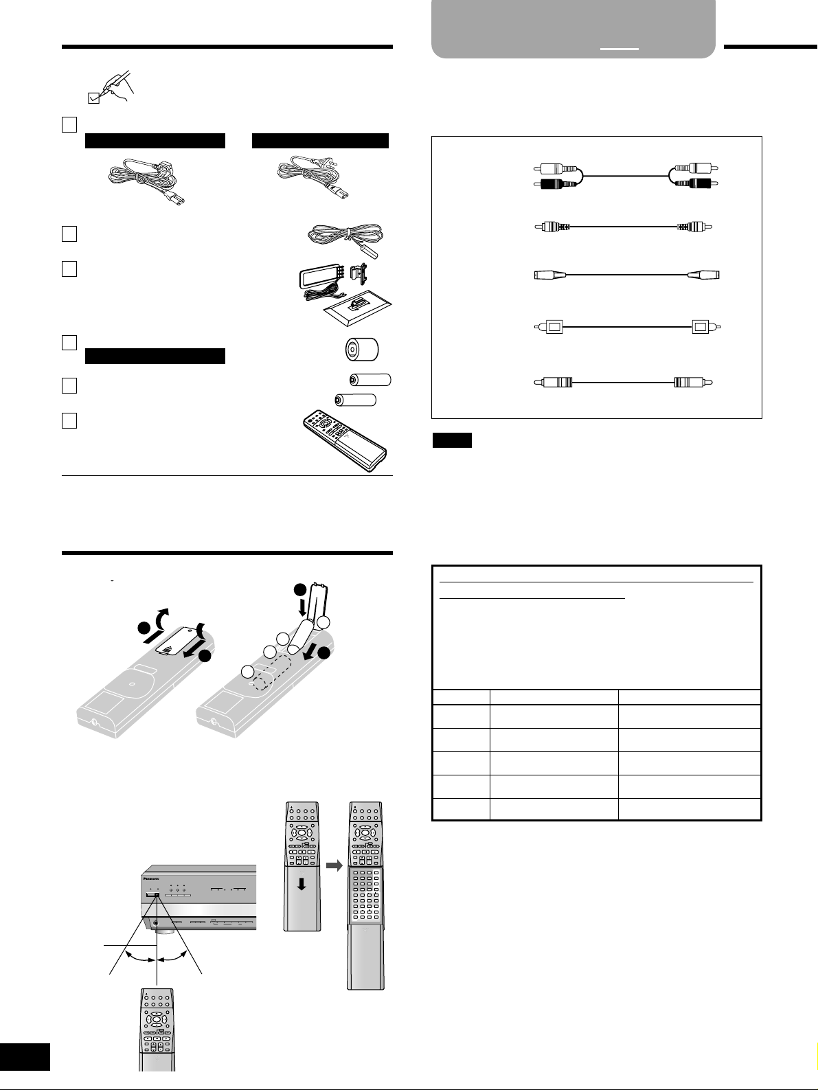
Please check and identify the supplied accessories.
1 AM loop antenna set (N1DAEYA00006)
(AM loop antenna, antenna stand,
antenna wall bracket)
Use the numbers indicated in parentheses when asking for
replacement parts.
1 FM indoor antenna (RSA0007-L)
2 Batteries
1 Remote control (EUR7502XC0)
1
4
2
3
+
–
–
+
(R6, AA, UM-3)
¡Insert so the poles (+ and –) match those in the remote control.
¡Do not use rechargeable type batteries.
■ Use
Aim at the sensor, avoiding obstacles,
at a maximum range of 7 m directly in
front of the unit.
The remote control
Refer to the separate booklet, “Remote
Control Operation Guide”, for remote
control operation details.
Step
1
2 3 4
Stereo phono cable
Video connection cable
Optical fiber cable
Coaxial cable
You can change the input settings for the digital
input terminals if necessary.
For example, if you have a DVD player that only has a
coaxial output terminal, connect it to COAXIAL IN, then
change the DVD setting from OPT 2 to COAX.
As you connect the equipment, fill in the table and make
changes to the settings as necessary (
\
page 11).
White (L)
Red (R)
S-video connection cable
¡Do not bend optical fiber cables.
¡Turn off all components before making any connections.
¡Use digital connection to enjoy Dolby Digital or DTS and record
digital sources (\page 16 and 22).
¡Use analogue connection to enjoy sources that cannot be
decoded on this unit and record analogue sources (\pages 16
and 22).
Note
■ Batteries
Supplied accessories
■ How to open
TV
TUNER/BAND
TOP MENU
MENU
RECEIVER
TAPEMD CD
VCR
DVD
RETURN
PAUSESTOP
SOUND MODE
CHANNEL VOLUME
PLAY
SLOW /SEARCH
SKIP
DISPLAY
MUTING
INPUT
SELECTOR
INPUT
SELECTOR
SUBWOOFER SUBWOOFER
ENTER
TV
TUNER/BAND
TOP MENU
MENU
RECEIVER
TAPEMD CD
VCR
DVD
RETURN
PAUSESTOP
SOUND MODE
CHANNEL VOLUME
PLAY
SLOW /SEARCH
SKIP
DISPLAY
MUTING
ENTER
36251
4
987
0
DIRECT TUNING/
DISC
ENHANCED
SURROUND
DOLBY
PROLOGIC 2
SFC
RE-MASTER
TESTNEO:6
10/-/--
INPUT MODE
DVD 6CH
TIMER
LEVELEFFECT
/ L
/ R
TONE
BALANCE
DIMMER
SETUPPAGE
AUDIO
GROUP
DVD
TV/AV
TV VOL
SOURCE DIRECT
To connect equipment, refer to the appropriate operating
instructions.
Peripheral equipment and cables sold separately unless
otherwise indicated.
CD
TV
DVD
DVR
MD/CD-R
COAX
OPT 1
OPT 2
OPT 3
OPT 4
Default settings Actual connectionsINPUT
TV
MD
TOP MENU
MENU
TUNER/BAND
RECEIVER
TAPE CD
VCR
DVD
RETURN
PAUSESTOP
SOUND MODE
CHANNEL VOLUME
PLAY
SLOW /SEARCH
SKIP
DISPLAY
MUTING
INPUT
SELECTOR
SUBWOOFER
ENTER
DOLBY
DIGITAL
DOLBY
PRO LOGIC 2
DTS-ESDOLBY
DIGITAL EX
RE-MASTER
WAKE
8
^
SOURCE DIRECT
NEO:6
DSP
SOUND MODE
DOLBY
PRO LOGIC 2
HQ
SOUND MODE
ENHANCED
SURROUND
DTS
MULTI DECODER
NEO:6
A SPEAKERS B
PHONES
RDS
- BAND
–
FM MODE
MEMORY
DISPLAY
MODE
PTY SEARCH PTY SELECTOR
PRESET2 TUNING
1
INPUT
MODE
TAPE
MONITOR
DVD
6CH INPUT
7 m
30˚ 30˚
1 AC mains lead
For the United Kingdom
For the United Kingdom
(VJA0733)
For continental Europe
(RJA0019-2K)
1 Antenna plug adapter (K1YZ02000013)
Page 5
FM
ANT
AM
ANT
LOOP
EXT
75Ω
GND
DIGITAL
OPTICAL1
(TV) IN
OPTICAL2
(DVD) IN
OPTICAL3
(DVR) IN
SURROUND
BACK
SUBWOOFER
COAXIAL
IN
IN
IN
CENTER
SUBWOOFER SURROUND
FRONT
RR
LL
R
L
OPTICAL
OUT
OPTICAL4
(MD/CD-R/RW) IN
PRE OUT
IN
INOUTINOUT
TV
IN
REC
(OUT)
PLAY
(IN)
REC
(OUT)
PLAY
(IN)
IN
VCR1
DVR/VCR2
TV
MONITOR
OUT
INOUT IN
A OR B : 4-16 Ω/EACH SPEAKER
A AND B : 8-16 Ω/EACH SPEAKER
6-16 Ω 6-16 Ω
6-16 Ω/EACH SPEAKER
SURROUND
BACK
CENTER
SURROUND
OUT
INOUT
DVD/DVD 6CH
S-VIDEO
VIDEO
L
R
PHONO
TAPE
CD
VCR1
DVR/VCR2
IN
OUT IN OUT IN
TV
MD/CD-R/RW
SPEAKERS
FRONT
B
R L
R L
R L
A
AC IN
5
RQT6252
Equipment connections
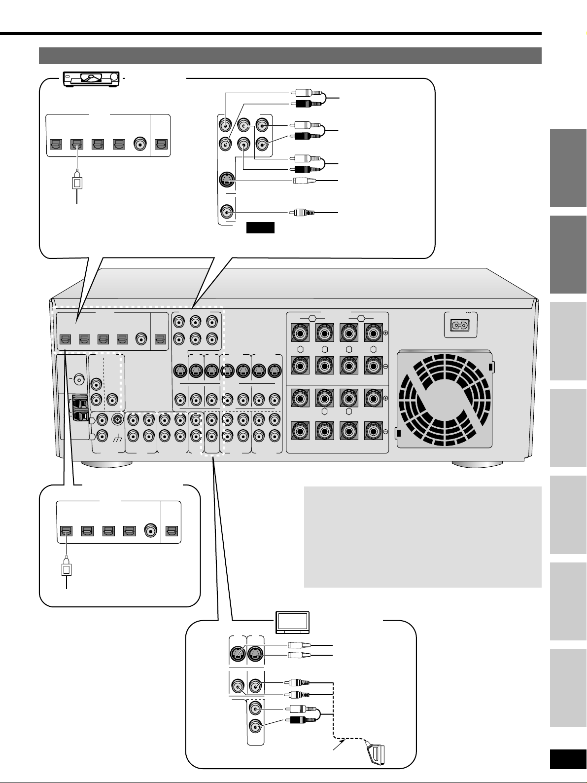
TV and DVD player
IN
IN
CENTER
SUBWOOFER SURROUND
FRONT
RR
LL
DVD/DVD 6CH
DVD player
VIDEO OUT
AUDIO OUT
(SURROUND L, R)
AUDIO OUT
(CENTER,
SUBWOOFER)
AUDIO OUT
(FRONT L, R)
Connect to FRONT L, R if your DVD player does
not have 6 channel output.
Note
DIGITAL
OPTICAL1
(TV) IN
OPTICAL2
(DVD) IN
OPTICAL3
(DVR) IN
COAXIALINOPTICAL
OUT
OPTICAL4
(MD/CD-R/RW) IN
DIGITAL AUDIO OUT
S-VIDEO OUT
Satellite receiver etc.
DIGITAL OUT
Step 1
Step 2
Step 3
Step 4
Before use
Others
Reference
DIGITAL
OPTICAL1
(TV) IN
OPTICAL2
(DVD) IN
OPTICAL3
(DVR) IN
COAXIALINOPTICAL
OUT
OPTICAL4
(MD/CD-R/RW) IN
Video
There are two types of connections: S-VIDEO, and VIDEO
(composite). Video input can only be output again through the
same type of terminal.
S-VIDEO
Use this connection for better picture quality than with the
VIDEO terminals.
VIDEO
This is the most basic video connection.
TV or monitor
IN
INOUT
TVTV
MONITOR
OUT
IN
TV
21-pin scart cable connection also possible.
VIDEO IN
VIDEO OUT
AUDIO OUT
S-VIDEO OUT
S-VIDEO IN
Page 6
FM
ANT
AM
ANT
LOOP
EXT
75
Ω
GND
DIGITAL
OPTICAL1
(TV) IN
OPTICAL2
(DVD) IN
OPTICAL3
(DVR) IN
SURROUND
BACK
SUBWOOFER
COAXIAL
IN
IN
IN
CENTER
SUBWOOFER SURROUND
FRONT
RR
LL
R
L
OPTICAL
OUT
OPTICAL4
(MD/CD-R/RW) IN
PRE OUT
IN
INOUTINOUT
TV
IN
REC
(OUT)
PLAY
(IN)
REC
(OUT)
PLAY
(IN)
IN
VCR1
DVR/VCR2
TV
MONITOR
OUT
INOUT IN
A OR B : 4-16 Ω/EACH SPEAKER
A AND B : 8-16 Ω/EACH SPEAKER
6-16 Ω 6-16 Ω
6-16 Ω/EACH SPEAKER
SURROUND
BACK
CENTER
SURROUND
OUT
INOUT
DVD/DVD 6CH
S-VIDEO
VIDEO
L
R
PHONO
TAPE
CD
VCR1
DVR/VCR2
IN
OUT IN OUT IN
TV
MD/CD-R/RW
SPEAKERS
FRONT
B
R L
R L
R L
A
AC IN
6
RQT6252
Equipment connections
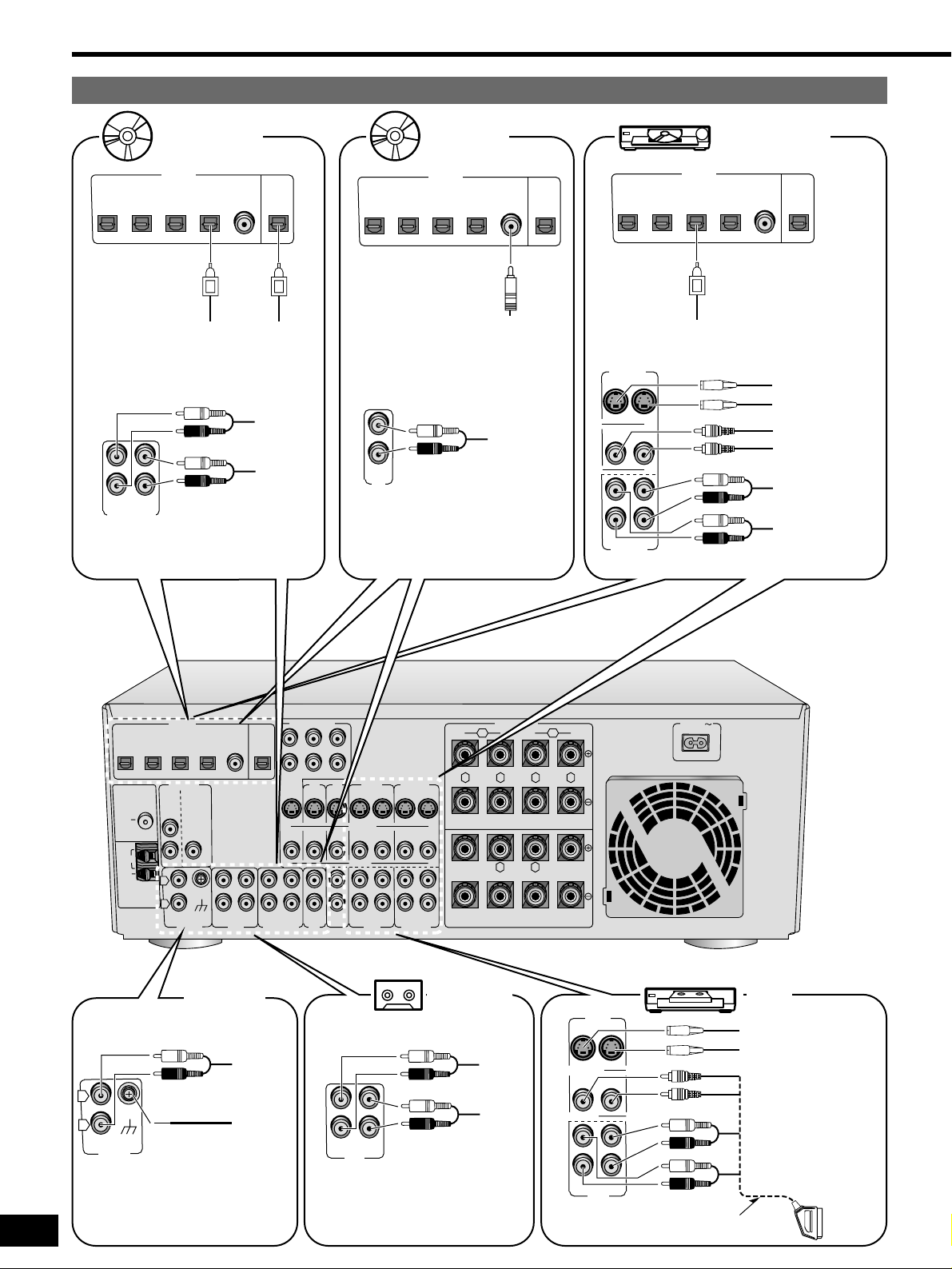
Other audio visual equipment
DVR/VCR2
INOUT
INOUT
DVR/VCR2
OUT IN
DVD recorder
VIDEO IN
AUDIO IN
AUDIO OUT
DIGITAL
OPTICAL1
(TV) IN
OPTICAL2
(DVD) IN
OPTICAL3
(DVR) IN
COAXIALINOPTICAL
OUT
OPTICAL4
(MD/CD-R/RW) IN
DIGITAL AUDIO OUT
VIDEO OUT
S-VIDEO OUT
S-VIDEO IN
CD Player
DIGITAL
OPTICAL1
(TV) IN
OPTICAL2
(DVD) IN
OPTICAL3
(DVR) IN
COAXIALINOPTICAL
OUT
OPTICAL4
(MD/CD-R/RW) IN
DIGITAL OUT
LINE
OUT
MD deck or
CD recorder
DIGITAL
OPTICAL1
(TV) IN
OPTICAL2
(DVD) IN
OPTICAL3
(DVR) IN
COAXIALINOPTICAL
OUT
OPTICAL4
(MD/CD-R/RW) IN
DIGITAL
OUT
PLAY
(OUT)
REC
(IN)
DIGITAL
IN
PLAY
(OUT)
REC
(IN)
If you have a graphic equalizer,
connect it to the TAPE terminals.
Tape deck
GND
IN
L
R
PHONO
PHONO
OUT
GND
Turntable
Connect if your turntable
has a ground terminal.
INOUT
VCR1
INOUT
S-VIDEO
VIDEO
VCR1
OUT IN
VCR
VIDEO IN
AUDIO IN
AUDIO OUT
VIDEO OUT
S-VIDEO OUT
S-VIDEO IN
21-pin scart cable
connection also possible.
REC
PLAY
(OUT)
(IN)
MD/CD-R/RW
CD
IN
REC
(OUT)
PLAY
(IN)
TAPE
Page 7
GND
DIGITAL
OPTICAL1
(TV) IN
OPTICAL2
(DVD) IN
OPTICAL3
(DVR) IN
SURROUND
BACK
SUBWOOFER
COAXIAL
IN
IN IN
Y
P
B
PR
R
L
OPTICAL
OUT
OPTICAL4
(MD/CD-R/RW) IN
PRE OUT
TV
IN
REC
(OUT)
PLAY
(IN)
REC
(OUT)
DVD
L
R
PHONO
TAPE
FM
ANT
AM
ANT
LOOP
EXT
75Ω
5–12 m
7
RQT6252
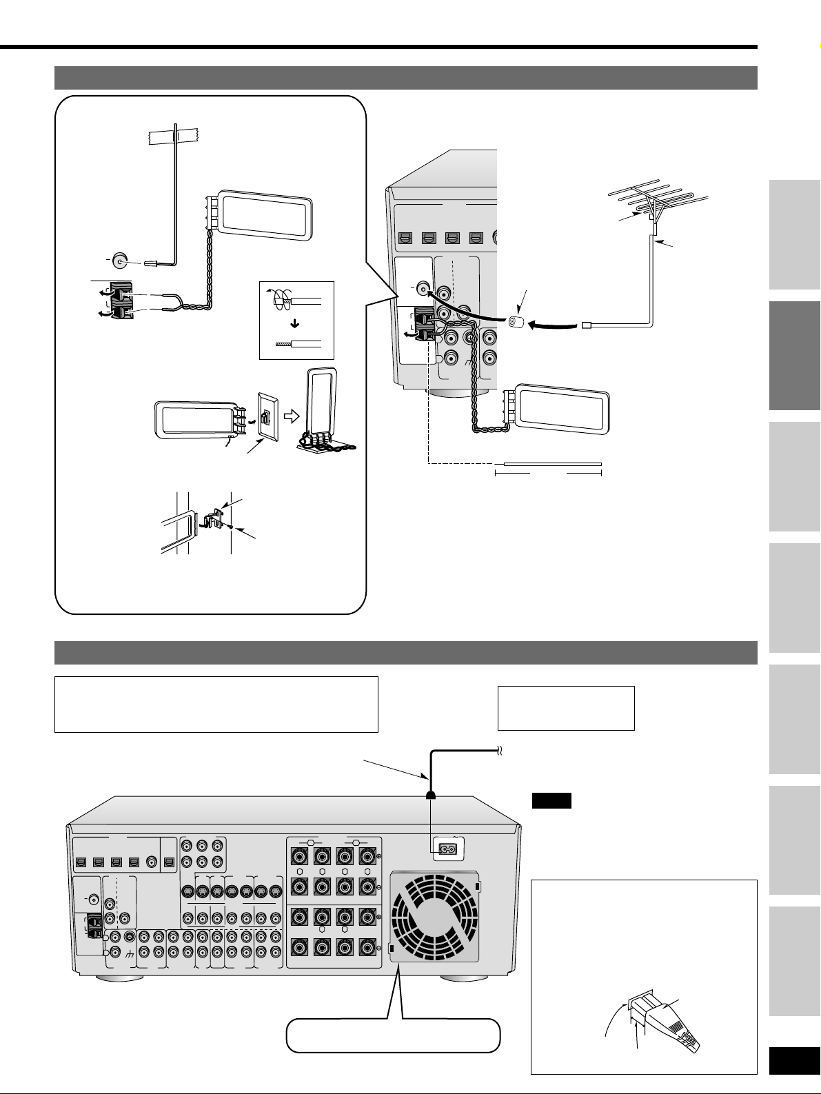
Antennas
The included AC mains lead is for use with
this unit only. Do not use it with other
equipment.
Note
To household mains socket
Connect this lead after
all other cables and
cords are connected.
AC mains lead (included)
Connecting the AC mains lead cord and other information
Fix the other end of the
antenna where reception
is best.
Adhesive tape
FM indoor antenna (included)
AM loop antenna
(included)
FM
ANT
AM
ANT
LOOP
EXT
75Ω
Keep the antenna cord away from tape decks, MD decks,
DVD players, and other cords.
Cooling fan
Operates at high power output levels only.
Step 1
Step 2
Step 3
Step 4
Before use
Others
Reference
FM outdoor antenna
¡Disconnect the FM indoor antenna.
¡The antenna should be installed by a
competent technician.
AM outdoor antenna
¡Run a piece of vinyl wire horizontally across a window or other
convenient location.
¡Leave the loop antenna connected.
¡Disconnect the antenna when the unit is not in use. Do not use
the antenna during an electrical storm.
FM outdoor
antenna
75 Ω coaxial cable
Vinyl-covered wire
AM loop antenna
(included)
Using the stand
Attach to the stand and place on a flat surface.
Screw
Wall bracket
(included)
When attaching the AM loop antenna to another
surface
AM antenna stand (included)
(For the United Kingdom)
Antenna plug
(included)
(FOR THE UNITED KINGDOM ONLY)
READ THE CAUTION FOR THE AC MAINS
LEAD ON PAGE 2 BEFORE CONNECTION.
Insertion of connector
Even when the connector is perfectly
inserted, depending on the type of inlet
used, the front part of the connector may
jut out as shown in the drawing .
However there is no problem using the
unit.
Connector
Approx. 6 mm
Appliance inlet
ANT
ANT
OPTICAL1
FM
(TV) IN
75Ω
LOOP
EXT
AM
OPTICAL2
(DVD) IN
DIGITAL
OPTICAL3
(DVR) IN
PRE OUT
SURROUND
BACK
L
R
L
R
SUBWOOFER
IN
PHONO
OPTICAL4
(MD/CD-R/RW) IN
GND
COAXIAL
IN
REC
(OUT)
TAPE
PLAY
(IN)
OPTICAL
OUT
REC
(OUT)
MD/CD-R/RW
DVD/DVD 6CH
CENTER
SUBWOOFER SURROUND
TV
MONITOR
IN
OUT
IN
PLAY
(IN)
IN
CD
LL
RR
FRONT
TV
IN
S-VIDEO
VIDEO
IN
OUT IN OUT IN
TV
VCR1
INOUT IN
INOUTINOUT
VCR1
DVR/VCR2
OUT
DVR/VCR2
INOUT
SPEAKERS
B
FRONT
R L
A OR B : 4-16 Ω/EACH SPEAKER
A AND B : 8-16 Ω/EACH SPEAKER
SURROUND
BACK
6-16 Ω 6-16 Ω
R L
SURROUND
6-16 Ω/EACH SPEAKER
R L
A
AC IN
CENTER
Page 8
YES NO
8
RQT6252
Speaker connections
Step
1
2
3 4
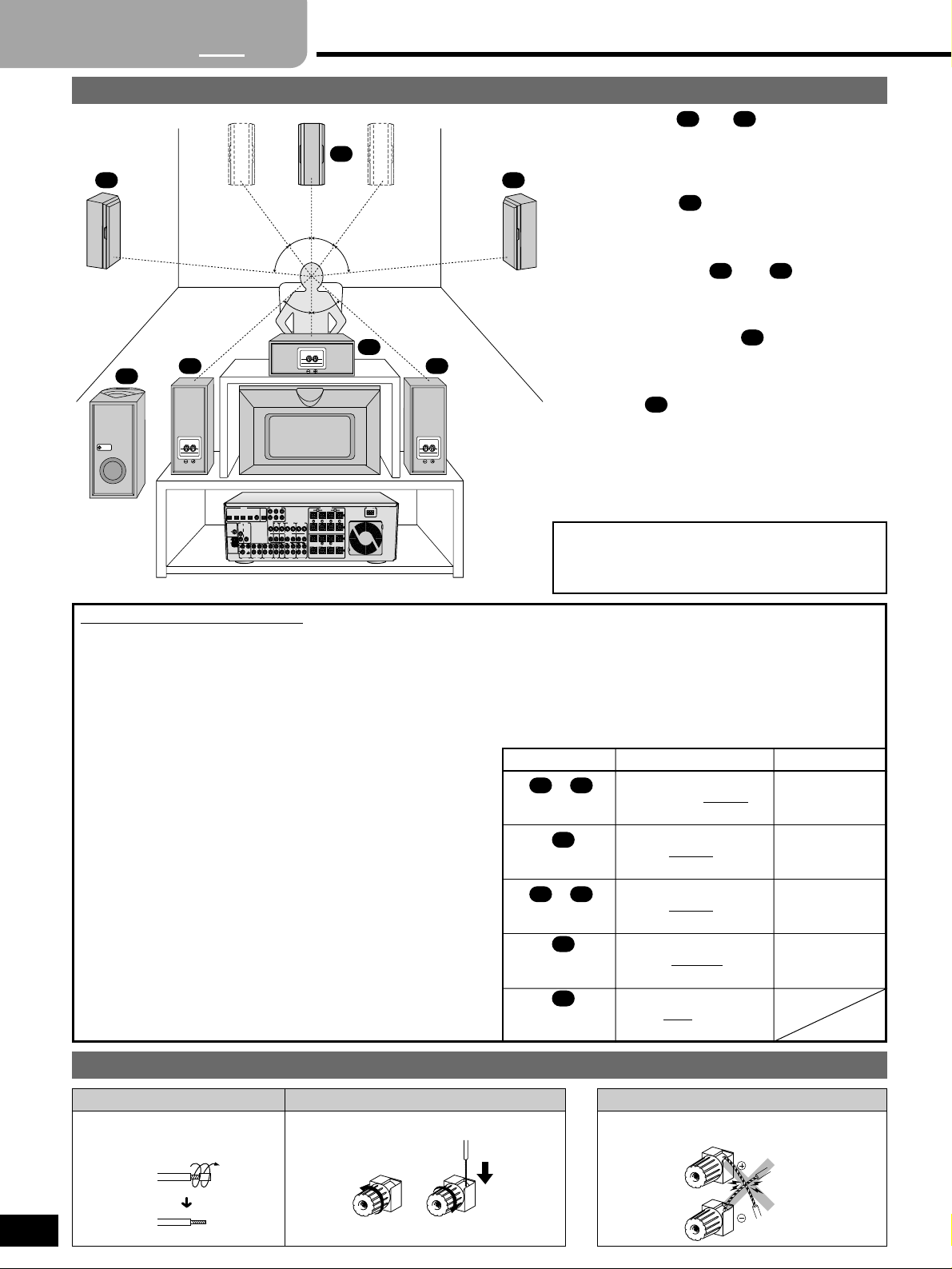
Placement of speakers
Front speakers ( left right)
Place on the left and right of the TV at seated ear height so
that there is good coherency between the picture and
sound.
Center speaker ( )
Place underneath or above the center of the TV. Aim the
speaker at the seating area.
Surround speakers ( left right)
Place on the side of or slightly behind the seating area,
about one meter higher than ear level.
Surround back speaker ( )
Place behind the seating area (slightly to the left and right
if you connect two), about one meter higher than ear level.
Subwoofer ( )
The subwoofer can be placed in any position as long as it
is at a reasonable distance from the TV.
Note that some experimentation can yield the smoothest
low frequency performance. Placement near a corner can
increase the apparent output level, but can result in
unnatural bass.
Do not short circuit.
Speaker cable
Cable Speaker terminals
Twist the wire
Note
SPEAKERS DISTANCE
SMALL LARGE
(3.0) m
NONE SMALL LARGE
FRONT
CENTER
SURROUND
SUR BACK
(SURROUND BACK)
SUB-WFR
(SUBWOOFER)
NONE SMALL
LARGE
NONE SINGLE DUAL
(3.0) m
(1.5) m
(1.5) m
Change the speaker settings.
To get the best performance from this unit and the speakers you connect to it, you need to change the settings described
below. As you connect the speakers, circle the corresponding SPEAKERS and fill in the approximate DISTANCE from the
seating area. Now go to page 10 and change the settings as necessary.
The front, center, and surround speakers should be
placed at approximately the same distance from the
seating area. The angles in the diagram are
approximate.
SPEAKERS
Change to suit the size and number of speakers you connect.
LARGE: For speakers that can reproduce a full sound range,
particularly the bass range below 100 Hz.
SMALL: For speakers that cannot adequately reproduce the
bass range. This setting is sufficient for most speakers
if you are using a subwoofer.
“SUB-WFR” is set to “YES” if you select this setting for
“FRONT”.
NONE: For speakers you haven’t connected (center, surround
or surround back). You cannot change the “SUR BACK”
setting if you select this setting for “SURROUND”.
SINGLE: If you connect one surround back speaker to the
speaker terminal.
DUAL: If you connect two surround back speakers via a power
amplifier to the pre-out terminal.
YES: If you connect a subwoofer.
NO: If you do not connect a subwoofer.
“FRONT” is set to “LARGE” if you select this setting.
DISTANCE
Change so the sound from the speakers reaches you at the
same time.
SLSR
SB
C
FL
FR
SW
FL
SW
SB
SL SR
C
FR
FL FR
C
SL SR
SB
SW
¡Factory settings for SPEAKERS are underlined.
¡Factory settings for DISTANCE are shown in parentheses.
45˚ 45˚
45˚ 45˚
30˚ 30˚
INPUT
DIGITAL
DVD/DVD 6CH
OPTICAL1
OPTICAL2
OPTICAL3
COAXIAL
OPTICAL
OPTICAL4
(TV) IN
(DVD) IN
(DVR) IN
IN
OUT
(CD-R/RW) IN
CENTER
SUBWOOFER SURROUND
PRE OUT
IN
FM
SURROUND
SUBWOOFER
ANT
BACK
L
75Ω
IN
R
P
O
O
L
EXT
L
AM
ANT
ND
G
R
REC
PLAY
REC
PLAY
(OUT)
(IN)
(OUT)
(IN)
IN
TAPE/MD
CD-R/RW
PHONO
SPEAKERS
R L
6-16 Ω/EACH SPEAKER
AC IN
A
FRONT
R L
CENTER
SURROUND
LL
B
RR
FRONT
R L
TV
VCR1
DVR/VCR2
TV
MONITOR
IN
INOUT IN
OUT
OUT
A OR B : 4-16 Ω/EACH SPEAKER
A AND B : 8-16 Ω/EACH SPEAKER
S-VIDEO
INOUT
INOUTINOUT
VIDEO
SURROUND
BACK
6-16 Ω 6-16 Ω
IN
IN
OUT IN OUT IN
TV
DVR/VCR2
VCR1
CD
Page 9

FM
ANT
AM
ANT
LOOP
EXT
75Ω
GND
DIGITAL
OPTICAL1
(TV) IN
OPTICAL2
(DVD) IN
OPTICAL3
(DVR) IN
SURROUND
BACK
SUBWOOFER
COAXIAL
IN
IN
IN
CENTER
SUBWOOFER SURROUND
FRONT
RR
LL
R
L
OPTICAL
OUT
OPTICAL4
(MD/CD-R/RW) IN
PRE OUT
IN
INOUTINOUT
TV
IN
REC
(OUT)
PLAY
(IN)
REC
(OUT)
PLAY
(IN)
IN
VCR1
DVR/VCR2
TV
MONITOR
OUT
INOUT IN
A OR B : 4-16 Ω/EACH SPEAKER
A AND B : 8-16 Ω/EACH SPEAKER
6-16 Ω 6-16 Ω
6-16 Ω/EACH SPEAKER
SURROUND
BACK
CENTER
SURROUND
OUT
INOUT
DVD/DVD 6CH
S-VIDEO
VIDEO
L
R
PHONO
TAPE
CD
VCR1
DVR/VCR2
IN
OUT IN OUT IN
TV
MD/CD-R/RW
SPEAKERS
FRONT
B
R L
R L
R L
A
AC IN
A OR B : 4-16 Ω/EACH SPEAKER
A AND B : 8-16 Ω/EACH SPEAKER
FRONT
B
R L R L
A
INPUT
SURROUND
BACK
SUBWOOFER
R
L
PRE OUT
SURROUND
BACK
SUBWOOFER
R
L
PRE OUT
6-16 Ω
6-16 Ω/EACH SPEAKER
SURROUND
BACK
SURROUND
R L
6-16 Ω
CENTER
9
RQT6252
Peripheral equipment and cables sold separately unless otherwise indicated.
Connecting speakers
Monaural
connection cable
Step 1
Step 2
Step 3
Step 4
Before use
Others
Reference
To connect two surround
back speakers
Power amplifier
Other connections are possible depending on your speaker system.
See your speaker system’s operating instructions for details.
Speaker
cable
Active
subwoofer
Subwoofer
Center speaker
– Impedance: 6–16 Ω
Front speakers
– Impedance:
A or B 4–16 Ω
If you connect speakers with an
impedance under 6 Ω, switch on
“LOW IMP” (\page 12).
A and B 8–16 Ω
Surround back speakers
– Impedance: 6–16 Ω
Surround speakers
– Impedance: 6–16 Ω
Right Left
Speaker cables
Right Left
Turn off the receiver before connecting the speakers.
“B” terminals
For connection to a second pair of
speakers.
Use the A terminals to enjoy
SURROUND, SFC and DVD 6CH INPUT.
Speaker
cable
Speaker
cables
Stereo
phono
cable
FL
FR
C
SLSRSB
SW
OR
Page 10
10
RQT6252
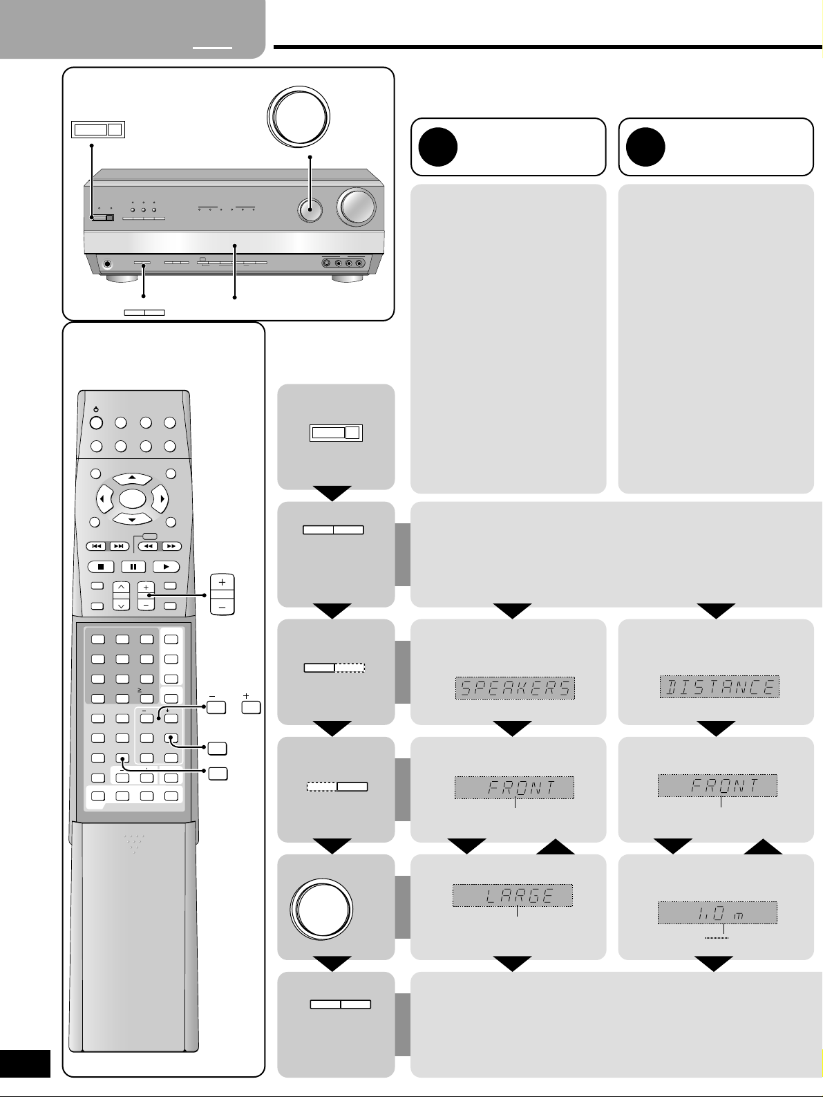
Settings
SPEAKERS DISTANCE
Change to suit the size and
number of speakers you
connect
Change the settings based on the
table you completed on page 8.
The factory settings are:
FRONT: LARGE
CENTER: SMALL
SURROUND: SMALL
SUR BACK: SINGLE
SUB-WFR: YES
Enter the distance of the front,
center and surround speakers
from the seating position
Change the settings based on the
table you completed on page 8.
You can select distances between
1.0 and 10.0 m at 0.1-meter intervals.
The factory settings are:
FRONT: 3.0 m
CENTER: 3.0 m
SURROUND: 1.5 m
SUR BACK: 1.5 m
1 2
Step
1 2
3
4
Press and
hold at the
same time
Enter the setting mode.
Select. Select.
Select. Select.
Change. Change.
Exit the setting mode.
INPUT
SELECTOR
SUBWOOFER
TV
TUNER/BAND
TOP MENU
MENU
RECEIVER
TAPEMD CD
VCR
DVD
RETURN
PAUSESTOP
SOUND MODE
CHANNEL VOLUME
PLAY
SLOW /SEARCH
SKIP
DISPLAY
MUTING
ENTER
3
6
251
4
987
0
DIRECT TUNING/
DISC
ENHANCED
SURROUND
DOLBY
PROLOGIC 2
SFC
RE-MASTER
TESTNEO:6
10/-/--
INPUT MODE
DVD 6CH
TIMER
LEVELEFFECT
/ L
/ R
TONE
BALANCE
DIMMER
SETUPPAGE
AUDIO
GROUP
DVD
TV/AV
TV VOL
SOURCE DIRECT
TEST
LEVEL
/ L
/ R
VOLUME
A SPEAKERS B
8
A SPEAKERS B
A SPEAKERS B
INPUT SELECTOR
A SPEAKERS B
Repeat.
Repeat.
FRONT, CENTER, SURROUND
SUR BACK, SUB-WFR
NONE, SMALL, LARGE
SINGLE, DUAL
NO, YES
FRONT, CENTER,
SURROUND, SUR BACK
1.0 m
10.0 m
See page 21 to change the DIMMER, DR COMP and A/D ATT
settings.
Press and
hold at the
same time
8
^
8
WAKE
PHONES
ENHANCED
HQ
RE-MASTER
SOUND MODE
SURROUND
DSP
DOLBY
NEO:6
SOURCE DIRECT
SOUND MODE
PRO LOGIC 2
A SPEAKERS B
A SPEAKERS B
INPUT SELECTOR
MULTI DECODER
DOLBY
DOLBY
DTS-ESDOLBY
DTS
- BAND
DISPLAY
FM MODE
MODE
PRO LOGIC 2
MEMORY
NEO:6
PRESET2 TUNING
PTY SEARCH PTY SELECTOR
1
DIGITAL
DIGITAL EX
INPUT
TAPE
DVD
RDS
MODE
MONITOR
6CH INPUT
–
INPUT SELECTOR
S-VIDEO IN VIDEO IN
DOWN UP
VCR 3
L AUDIO IN R
DISPLAY
VOLUME
Page 11
11
RQT6252
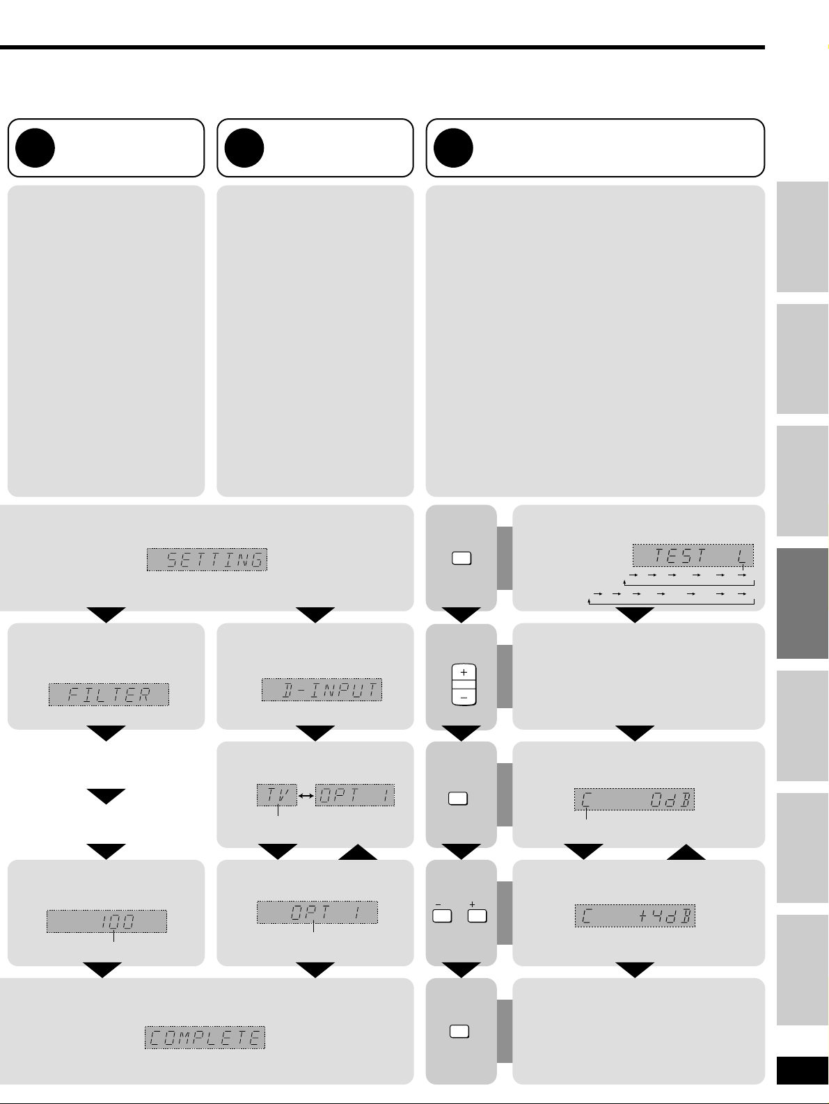
Change the settings to suit your speakers and units to the environment in which you are using them. Before making any changes, read the
descriptions of the settings, note the factory settings and ranges, and refer to the equipment’s instructions.
FILTER
Change the cut-off for bass
output from the front speakers
If you set the front speakers to
“SMALL”, the filter is set to 100 Hz.
Raise the cut-off if the bass from the
front speakers is unsatisfactory so
that this bass is output through the
subwoofer.
You can raise the cut-off from 100 Hz
to either 150 Hz or 200 Hz.
Adjusting speaker output level
Adjust the level of the other speakers based on the output of the
front speakers. (Speakers set as “NONE” or “NO” are skipped.
Adjust the volume of the front speakers with [VOLUME].)
C (center), SR (surround right), SB (surround back)(SBR–
surround back right– and SBL–surround back left– when DUAL
selected), and SL (surround left) can be adjusted between –10 dB
and +10 dB, with 0 being the level of the front speakers.
Adjust center, surround and surround back output to the same
apparent level of the front speakers.
For SW (subwoofer), you can select “---” so there is no output,
“MIN” for minimum output, a level between 1 and 19, or “MAX” for
maximum output.
Adjust subwoofer output so it is balanced with the front speakers.
Subwoofer output is easily influenced by the source. You can also
change its level while playing something for better effect
(\page 15).
Preparation: Turn SPEAKERS A on.
3 5
D-INPUT
Digital input
Change the settings based on the
table you completed on page 4 so that
the correct source is selected when
you turn [INPUT SELECTOR].
The factory settings are:
TV: OPT 1
DVD: OPT 2
DVR: OPT 3
MD/CD-R: OPT 4
CD: COAX
4
Step 1
Step 2
Step 3
Step 4
Before use
Others
Reference
Select. Select.
Select.
Change. Change.
Output the signal.
Adjust the main volume.
Select the speaker channel.
Stop the test signal.
Adjust the level.
The “SURROUND” DSP mode is engaged.
TEST
VOLUME
LEVEL
Repeat.
Repeat.
100, 150, 200
OPT 1, OPT 2, OPT 3,
OPT 4, COAX
TV, DVD, DVR,
MD/CD-R, CD
LCRSRSBSLSW
L C R SR SBR SLSBL SW
“SINGLE”
“DUAL”
C, SR, SB (SBR, SBL), SL, SW
Two seconds each.
/ L
/ R
TEST
Page 12
12
RQT6252
DOLBY
DIGITAL
DOLBY
PRO LOGIC 2
DTDOLBY
DIGITAL EX
RE-MASTER
WAKE
8
^
SOURCE DIRECT
NEO:6
DSP
SOUND MODE
DOLBY
PRO LOGIC 2
HQ
SOUND MODE
ENHANCED
SURROUND
MULTI DECO
A SPEAKERS B
PHONES
RDS
- BAND
–
FM MODE
MEMORY
DISPLAY
MODE
INPUT
MODE
TAP E
MONITOR
DVD
6CH INPUT
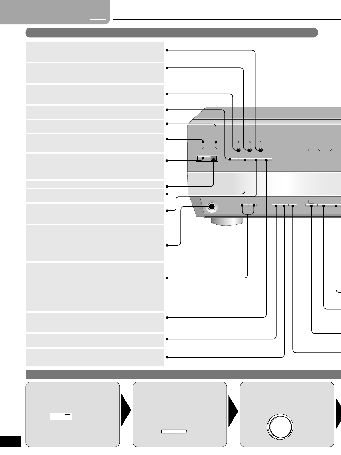
Standby/on switch [8]
Press to switch the unit from on to standby mode or vice versa.
In standby mode, the unit is still consuming a small amount of
power.
[SPEAKERS, A, B]
For selecting speakers A or B.
Turning the speakers off automatically engages the STEREO
mode (when listening through headphones, for example).
If your speakers have an impedance under 6 Ω
Press and hold [A] or [B] until “LOW IMP” lights up on the display.
Note that when “LOW IMP” is on, SPEAKERS A and B cannot be
used at the same time.
[DVD 6CH INPUT]
For switching between 6-channel and 2-channel DVD input.
When you select DVD 6CH, SOURCE DIRECT mode is on.
[PHONES]
Headphone jack
Plug type: 6.3 mm stereo
Avoid listening for prolonged periods of time to prevent hearing
damage.
Turn the speakers off when using the headphones.
[DSP SOUND MODE]
For selecting “STEREO”, “SURROUND” or “SFC”.
[DOLBY PRO LOGIC 22]
For selecting a Dolby Pro Logic 2 mode: MOVIE, MUSIC or PANORAMA.
Use when “DOLBY PRO LOGIC 2” lights in the SURROUND mode.
[NEO:6]
For selecting a DTS NEO:6 mode: CINEMA or MUSIC.
Use when “NEO:6” lights in the ENHANCED SURROUND mode.
[ENHANCED SURROUND]
For turning on the enhanced surround mode. The indicator lights
when the mode is on.
Switch on.
8
Turn
SPEAKERS A
on.
Select input.
1
2
3
[HQ SOUND MODE]
For selecting the HQ sound mode. The indicator lights when the
mode is on.
[RE-MASTER]
For selecting a re-master mode. The indicator lights while a remaster mode is on.
[SOURCE DIRECT]
For selecting a source direct mode.
Standby indicator [^]
When the unit is connected to the AC mains supply, this indicator
lights up in standby mode and goes out when the unit is turned on.
[WAKE]
Wake timer indicator
Remote control sensor
[INPUT MODE]
For selecting AUTO, ANALOG or DIGITAL.
Control guide
Step
1 2 3
4
Basic operations
A SPEAKERS B
INPUT SELECTOR
Main unit
Page 13
13
RQT6252
S-ES DTS
DER
NEO:6
INPUT SELECTOR
VOLUME
DOWN UP
PTY SEARCH PTY SELECTOR
PRESET2 TUNING
1
VCR 3
S-VIDEO IN VIDEO IN
L AUDIO IN R
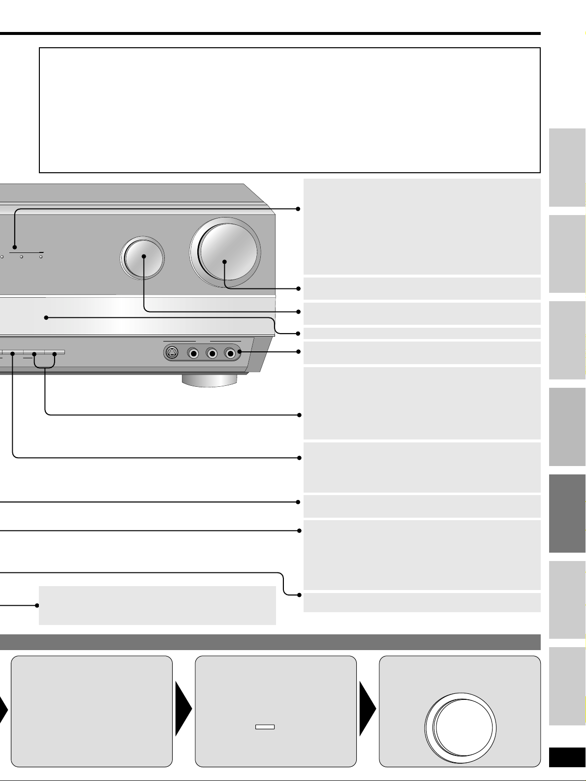
[VOLUME]
Volume control.
[MEMORY]
For presetting radio stations.
[INPUT SELECTOR]
For selecting input.
[TAPE MONITOR]
For monitoring sound when recording to a 3 head cassette deck.
Also used when you have connected a graphic equalizer to the
TAPE terminals.
[TUNING, 2, 1, PTY SELECTOR]
TUNING;
For tuning the radio and selecting preset stations.
Press and hold until the frequency starts scrolling to start
automatic tuning. Tuning stops when a station is found.
PTY SELECTOR;
For changing the PTY display.
[PRESET, PTY SEARCH]
PRESET;
Press to allow preset station selection with [TUNING, 2, 1]
PTY SEARCH;
For starting a PTY search.
[RDS]
Press to use the RDS functions.
[VCR 3]
For a video camera, etc.
[MULTI DECODER]
Light to indicate the source’s input signal and decoding format
used.
DOLBY DIGITAL EX: Dolby Digital Surround EX sources
DOLBY DIGITAL: Dolby Digital sources
DOLBY PRO LOGIC 22:
Dolby Pro Logic 2 decoder is being used
DTS-ES: DTS-ES discrete or matrix sources
DTS: DTS sources
NEO:6: DTS NEO:6 matrix decoder is being used
Select the DSP
sound mode.
Start play of the
source.
Adjust the
volume.
VOLUME
DOWN UP
5
4
6
DSP
SOUND MODE
[-BAND, –FM MODE, DISPLAY MODE ]
-BAND, –FM MODE;
For switching between AM and FM.
If reception is poor in FM, press and hold until “MONO” appears to
switch to monaural mode.
DISPLAY MODE;
For changing the RDS display mode: PS, PTY or RT.
Display (\page 14)
For your reference
¡When playing videotapes (connected to VCR 1)
The picture remains on the screen even if you select TAPE, CD,
MD/CD-R, TUNER or PHONO.
¡Once you have set a mode (DSP, AUTO/DIGITAL/ANALOG
input, or 2-channel/6-channel input) for an input source
That mode is engaged whenever you reselect the input source.
¡When using a graphic equalizer
Some distortion may occur, depending on the equalizer’s
settings.
¡When SPEAKERS B is on
The STEREO DSP SOUND mode is engaged automatically.
¡When you finish listening
Be sure to reduce the volume and press [8] to switch the unit
to standby.
¡When DTS FIX mode is on
You cannot use ENHANCED SURROUND and DTS-ES signals
will be played through 5.1 channels (i.e., there will be no sound
from the surround back speaker).
¡When input is DIGITAL
The tape monitor cannot be used.
(\pages 16 and 17)
Step 1
Step 2
Step 3
Step 4
Before use
Others
Reference
Page 14
TUNED
MONO
STEREO
PTY
PS RT
SLEEP
WAKE
LOW IMP
SPEAKERS
kHz
MHz
INPUT MODE
DIGITAL ANALOG
LCRSLS
TAPE MONITOR
SB SR LFE
DIRECT 12
SOUND MODE
STEREO
SURROUND
OVER FIXED PCM
DTS
SFC
M
A
B
ATT
RDS
14
RQT6252
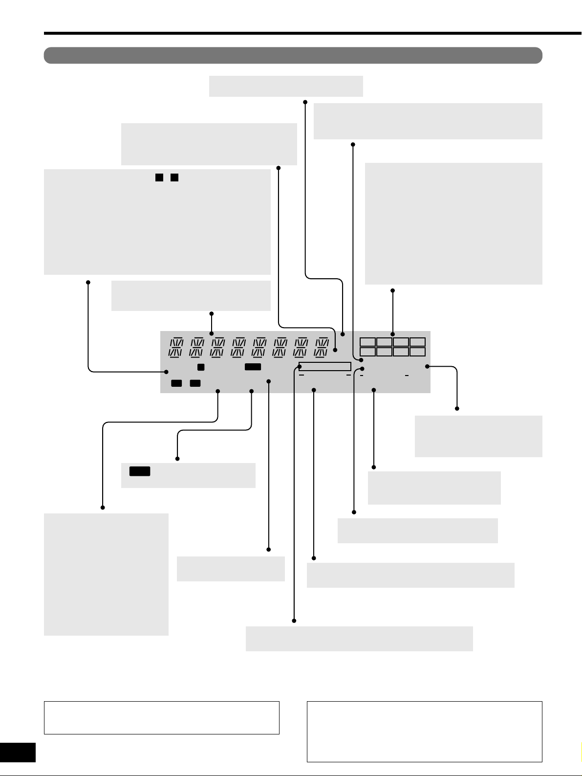
[SOUND MODE, STEREO,
SURROUND, SFC]
Show the current DSP sound mode.
[kHz, MHz]
Frequency unit indicators
kHz: AM, or PCM sampling frequency
MHz: FM
[L, C, R, S, SL, SB, SR, LFE]
Program format indicators
Show the channels contained in the digital input
signal. They do not light when input is analogue.
L: Front left channel
C: Center channel
R: Front right channel
S: If the surround channel is monaural.
SL: Surround left channel
SB: Surround back channel
SR: Surround right channel
LFE (Low Frequency Effect): Deep-bass effect.
[LOW IMP, SPEAKERS , ]
Speaker indicators
LOW IMP:You have switched to LOW IMP because you have
connected speakers with an impedance under 6 Ω.
SPEAKERS Å: Sound is output from speakers connected to
the front A, surround, and center terminals.
SPEAKERS ı: Sound is output only from speakers connected
to the front B terminals.
SPEAKERS Åı: Sound is output from speakers connected to
the front A and B terminals.
BA
[FIXED, PCM, DTS]
Light when a fix mode is selected.
FIXED PCM: PCM FIX mode
FIXED DTS: DTS FIX mode
[TUNED, STEREO,
MONO, ˜]
Radio indicators
TUNED: A station is tuned.
MONO: You have switched to
monaural mode with
[-BAND, –FM MODE,
DISPLAY MODE] to
improve reception.
STEREO: A stereo FM broadcast
is tuned.
˜: Flashes during presetting.
General display
Shows the input mode, radio frequency, and
other general information.
[OVER]
Lights when input exceeds rated values.
Turn the A/D attenuator on if this occurs frequently (\page 21).
[ATT]
Lights when the A/D attenuator is working.
Manufactured under license from Dolby Laboratories.
“Dolby”, “Pro Logic” and the double-D symbol are trademarks of
Dolby Laboratories.
Manufactured under license from Digital Theater Systems, Inc.
US Pat. No. 5,451,942, 5,956,674, 5,974,380, 5,978,762 and
other world-wide patents issued and pending.
“DTS”, “DTS-ES Extended Surround” and “Neo:6” are
trademarks of Digital Theater Systems, Inc. Copyright 1996,
2000 Digital Theater Systems, Inc. All rights reserved.
Control guide
[WAKE, SLEEP]
Wake/sleep timer indicators.
[ , PS RT, PTY]
Show the current RDS display mode.
RDS
[TAPE MONITOR]
Lights when the tape monitor is on.
[DIRECT 1 2]
Lights when source direct mode is selected.
[INPUT MODE, DIGITAL, ANALOG]
Input indicators
Display
Page 15
15
RQT6252
INPUT
SELECTOR
SUBWOOFER
TV
TOP MENU
MENU
TUNER/BAND
RECEIVER
TAPEMD CD
VCR
DVD
RETURN
PAUSESTOP
SOUND MODE
CHANNEL VOLUME
PLAY
SLOW /SEARCH
SKIP
DISPLAY
MUTING
ENTER
3
6
2
5
1
4
987
0
DIRECT TUNING/
DISC
ENHANCED
SURROUND
DOLBY
PROLOGIC 2
SFC
RE-MASTER
TESTNEO:6
10/-/--
INPUT MODE
DVD 6CH
TIMER
LEVELEFFECT
/ L
/ R
TONE
BALANCE
DIMMER
SETUPPAGEAUDIO GROUP
DVD
TV/AV
TV VOL
SOURCE DIRECT
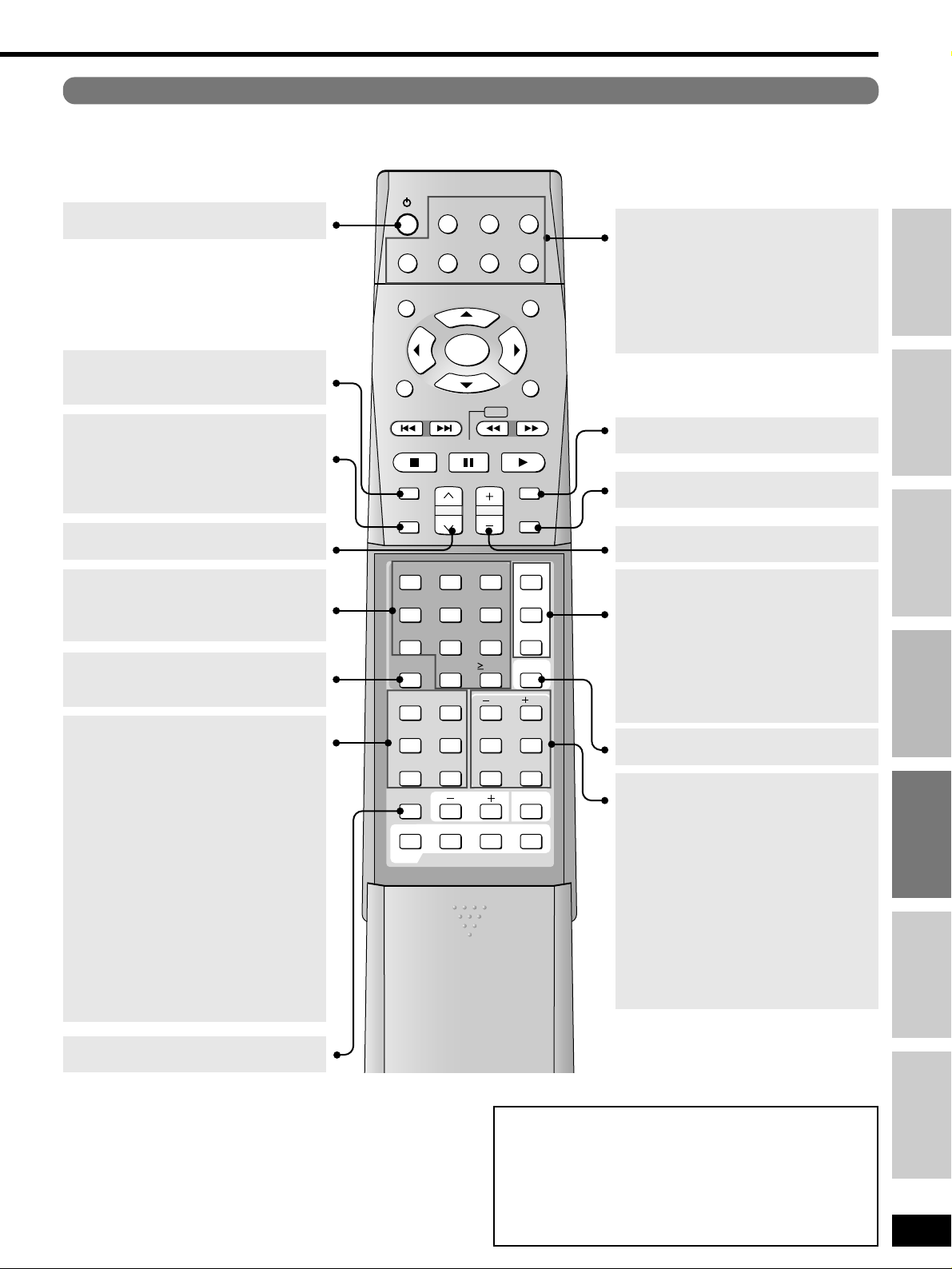
[SUBWOOFER]
For selecting subwoofer level.
Adjust the level in 5 steps
SW MIN, SW 5, SW 10, SW 15, and SW
MAX.
Select SW --- to stop output.
[–/L, +/R]
First select EFFECT, LEVEL, TONE or
BALANCE, then press [–/L] or [+/R] to
adjust.
[EFFECT]
Use when adjusting Dolby Pro Logic 2,
DTS NEO:6, or SFC effects
[LEVEL]
Use when adjusting speaker level.
[TONE]
To adjust the bass and treble.
[BALANCE]
To adjust the front speaker balance.
[^]
Standby/on button
[TV, VCR, DVD,
TUNER/BAND RECEIVER, MD,
TAPE, CD]
Input mode and remote control mode
buttons.
These buttons light when you press other
buttons to indicate the current remote control
mode.
[VOLUME, +, –]
To adjust the volume.
[TIMER]
For setting the wake/sleep timer.
[MUTING]
To mute the volume.
[INPUT SELECTOR]
To select input source.
[SOUND MODE]
For selecting “STEREO”, “SURROUND” or
“SFC”
[1, 2, 3, 4, 5, 6, 7, 8, 9, 0]
To enter radio frequencies and channels.
[≥10/-/--]
To enter two digit channels.
[ENHANCED SURROUND]
For turning on the enhanced surround mode.
[RE-MASTER]
For selecting a re-master mode.
[DOLBY PRO LOGIC 22]
For selecting a Dolby Pro Logic 2 mode:
MOVIE, MUSIC or PANORAMA.
Use when “DOLBY PRO LOGIC 2” lights in
the SURROUND mode.
[SFC]
For selecting SFC modes.
[NEO:6]
For selecting a DTS NEO:6 mode: CINEMA
or MUSIC.
Use when “NEO:6” lights in the ENHANCED
SURROUND mode.
[TEST]
To start the speaker test signal.
[DIMMER]
For dimming the unit’s display.
[SOURCE DIRECT]
For selecting a source direct mode.
[INPUT MODE]
For selecting AUTO, ANALOG or DIGITAL.
[DVD 6CH]
For switching between 6-channel and 2channel DVD input.
When you select DVD 6CH, SOURCE
DIRECT mode is on.
[DIRECT TUNING/DISC]
To enable selection of radio stations by
frequency.
[CHANNEL, 1, 2]
For selecting preset radio channels.
Buttons not explained on this page are used only to operate other equipment. Refer to
the separate Remote Control Operation Guide for details.
For your reference
¡When using the subwoofer
You cannot adjust subwoofer level while the SOURCE DIRECT
mode is on or if DVD 6CH INPUT is selected.
Sound can be distorted if you raise the volume while subwoofer
level is high. Reduce subwoofer level if this occurs.
¡When muting is on
Muting is also canceled when the unit is turned off.
Remote control
Step 1
Step 2
Step 3
Step 4
Before use
Others
Reference
Page 16
For your reference
In rare cases, the unit may have trouble recognizing the digital
signals on discs.
¡With the PCM signals on CDs, this may cause the beginning of a
track to be cut off. Engage the PCM FIX mode if this occurs.
¡With DTS, the signals may not be recognized at all. Engage the
DTS FIX mode if this occurs.
While the input source is selected:
11
Press [INPUT MODE] to select “DIGITAL”.
22
Press and hold [INPUT MODE].
The current mode is displayed. Press again to change the mode.
Each time you press the button:
AUTO / PCM FIX / DTS FIX
When a FIX mode is on, the unit cannot process other signals. This
may cause noise to be output. Select “AUTO”if this occurs.
The selected mode is stored for each input source even if the unit is
turned off.
16
RQT6252
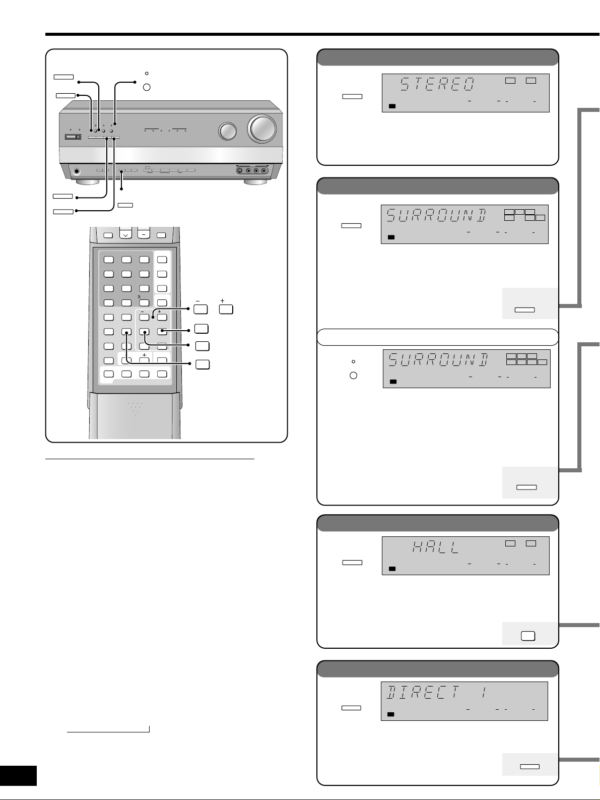
Use this mode to play digital or analogue stereo sources or to
play surround sources through two speakers. When surround
sources are played in this mode, the sounds intended for the
other speaker channels are played through the front speakers.
Select this mode when you are playing a digital surround source
(Dolby Digital or DTS).
Also select this mode when playing analogue or digital stereo
sources. Dolby Pro Logic 2 decoder works not
only on sources recorded with Dolby Surround, but
also on any stereo source. The following modes
are available when using Dolby Pro Logic 2.
Enjoy an enhanced sound experience with greater presence and
spread by using these SFC (sound field control) modes with PCM
or analogue stereo sources.
The SFC modes cannot be used if the input signal
is Dolby Digital or DTS.
Choose from the following modes.
INPUT
SURROUND mode
STEREO mode
SFC modes
ENHANCED SURROUND mode
SPEAKERS
INPUT MODE
DIGITAL
LCR
SL
SR LFE
SOUND MODE
SURROUND
A
DSP
SOUND MODE
This mode uses the surround back speaker to create a realistic
sound field. It is especially effective when playing DTS-ES and
Dolby Digital Surround EX, but can be used with other DTS and
Dolby Digital sources. This mode engages automatically if the
disc has a recognition signal for DTS-ES or Dolby Digital
Surround EX (you can still turn the mode off).
Use DTS NEO:6 to play 5.1-channel DTS, 2-channel PCM, and
analogue sources through 6.1 channels.
The following modes are available when playing
2-channel PCM and analogue sources.
Notes on using the Digital Signal Processor
The digital signal processor in this unit can decode the
following signals:
¡¡
Dolby Digital, including Dolby Digital Surround EX
¡¡
DTS, including DTS-ES
¡¡
PCM, including PCM with sampling frequencies of 96 or
88.2 kHz
It cannot decode:
¡Other digital signals, such as MPEG
¡Dolby Digital RF signals from a laser disc player
When playing PCM with sampling frequencies of 96 or 88.2 kHz,
the STEREO DSP mode is engaged automatically.
Use this mode to enjoy pure sound from digital and analogue
sources, unaltered by this unit’s DSP and other circuits.
Choose from the following modes.
SOUND MODE
STEREO
ANALOG
SPEAKERS
INPUT MODE
DIRECT 1
A
SOURCE DIRECT
SOURCE DIRECT modes
Sound modes
/
DSP
SOUND MODE
SOURCE DIRECT
^
WAKE
8
PHONES
DOLBY
PRO LOGIC 2
NEO:6
RE-MASTER
SOURCE DIRECT
SOUND MODE
A SPEAKERS B
ENHANCED
HQ
SOUND MODE
SURROUND
DSP
DOLBY
PRO LOGIC 2
SUBWOOFER
1
4
DIRECT TUNING/
DISC
ENHANCED
SURROUND
DOLBY
PROLOGIC 2
DIMMER
DVD
NEO:6
INPUT
MODE
INPUT
MODE
RE-MASTER
SFC
TESTNEO:6
DVD
6CH INPUT
5
0
TV VOL
ENHANCED
SURROUND
DIGITAL EX
TAPE
MONITOR
10/-/--
TONE
DOLBY
PRO LOGIC 2
DIGITAL
- BAND
RDS
FM MODE
–
DISPLAY
MODE
SELECTOR
362
SOURCD DIRECT
INPUT MODE
DVD 6CH
987
TIMER
/ L
LEVELEFFECT
BALANCE
SETUPPAGEAUDIO GROUP
MULTI DECODER
DOLBY
MEMORY
/ R
TV/AV
DTS-ESDOLBY
PRESET2 TUNING
PTY SEARCH PTY SELECTOR
INPUT SELECTOR
DTS
NEO:6
1
/ L
DOWN UP
VCR 3
S-VIDEO IN VIDEO IN
/ R
LEVEL
EFFECT
SFC
L AUDIO IN R
DSP
SOUND MODE
SPEAKERS
VOLUME
A
INPUT MODE
DIGITAL
LR
SOUND MODE
STEREO
DOLBY
PRO LOGIC 2
LCR
SL
ENHANCED
SURROUND
SPEAKERS
A
INPUT MODE
DIGITAL
SB SR LFE
SOUND MODE
SURROUND
NEO:6
DSP
SOUND MODE
SPEAKERS
A
INPUT MODE
DIGITAL
LR
SFC
SOUND MODE
SFC
SOURCE DIRECT
Page 17
17
RQT6252
Step 1
Step 2
Step 3
Step 4
Before use
Others
Reference
You can adjust the sound field by adjusting the level of the
speakers and the delay time of the surround speakers. These
adjustments can be made for each SFC mode.
To adjust the speaker level
11
Press [LEVEL] to select the speaker channel.
Each time you press the button:
C / SR / SL / SW
↑
Sound does not come from the surround back speaker(s).
Speakers set as “NONE” or “NO” are skipped.
22
Press [–/L] or [+/R] to adjust the level.
C, SR, and SL: –10 dB to +10 dB
SW: --- (off) ,/ MIN ,/ 1 – 19 ,/ MAX
To adjust the delay time
11
Press [EFFECT] .
22
Press [–/L] or [+/R] to change the delay time.
Delay time can be set at 10-millisecond (ms) intervals between
10 and 100 ms.
The factory setting is 50 ms for each mode.
You can adjust the effect of MUSIC and PANORAMA with the
center width and dimension controls.
Center Width Control – C-WDTH
This adjustment helps you realize a more natural sound image
when listening to music. Move sound out into the front speakers
to improve the overall front image, or add sound to the center
speaker to fix the center image.
You can choose a level between 0 (the center speaker is
dominant) and 7 (center sound is spread out).
The default level is 3.
11
Press [EFFECT] to select “C-WDTH”.
22
Press [–/L] or [+/R] to adjust the effect.
Dimension Control – DIMEN
You can make up for differences in the output level of the front
and surround speakers.
You can choose a level between –3 and +3 – Increase the level
to move sound to the front speakers, decrease to move it to the
surround speakers.
The default is level 0.
11
Press [EFFECT] to select “DIMEN”.
22
Press [–/L] or [+/R] to adjust the effect.
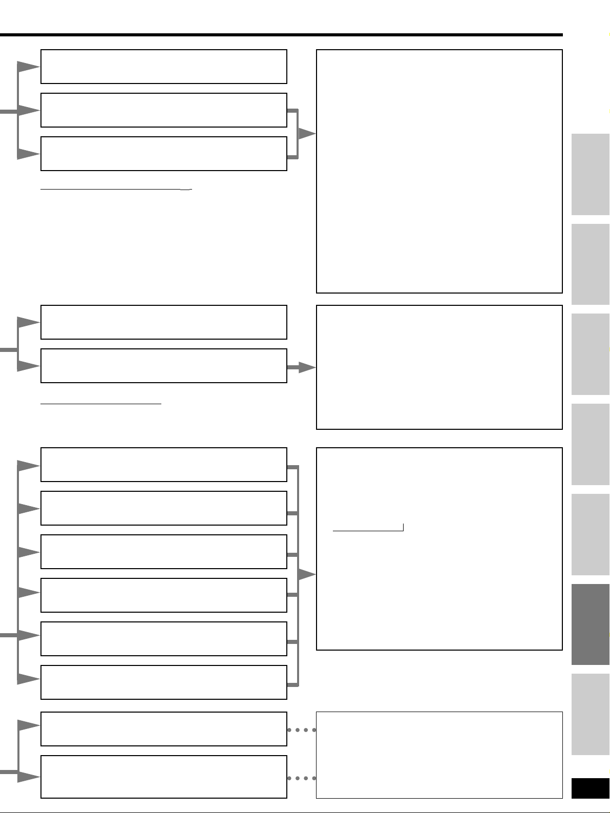
HALL
Imparts the reflection and spread of a large concert hall.
CLUB
Conveys the exciting and intimate atmosphere of a jazz club.
LIVE
Brings you up close for “live” stage performance and smoother
vocals.
THEATER
Recreates natural sound ambience and direction.
SIM SURR (Simulated Surround)
Heightens the sensation of expanded space with stereo sources,
and augments monaural sources.
PARTY
This mode uses the front and surround speakers so that sound is
in stereo regardless of the direction you are facing.
MOVIE
Use this mode when playing movie software, especially
videotapes, recorded in Dolby Surround.
MUSIC
Adds surround effects to stereo sources.
PANORAMA
Sound is spread out more so you feel like you are surrounded by
music.
CINEMA
Use this mode when playing movie software.
MUSIC
Adds surround effects to stereo sources.
You can adjust the effect of MUSIC with the center image control.
Center Image Control – C-IMG
This adjustment helps you realize a more natural sound image
when listening to music. Move sound out into the front speakers
to improve the overall front image, or add sound to the center
speaker to fix the center image.
You can choose a level between 0 (the center speaker is
dominant) and 5 (center sound is spread out).
The default level is 3.
11
Press [EFFECT] to select “C-IMG”.
22
Press [–/L] or [+/R] to adjust the effect.
Notes on using DTS NEO:6
You cannot select the above modes when the “DTS” indicator is lit.
Notes on using Dolby Pro Logic
22
ENHANCED SURROUND turns off if you select a Dolby Pro Logic
2 mode.
DIRECT 1
Enjoy pure stereo sound.
DIRECT 2
Further purifies sound by shutting off video signals, turning off the
display (unless input is TUNER), and turning on the HQ SOUND
MODE.
SOURCE DIRECT 1 or 2 turns off if you:
– Select SURROUND mode,
– Select ENHANCED SURROUND mode,
– Select SFC modes, or
– Select RE-MASTER modes,
While the SOURCE DIRECT 1 or 2 mode is selected, you cannot:
– Adjust the tone, or
– Use the subwoofer.
Page 18
18
RQT6252
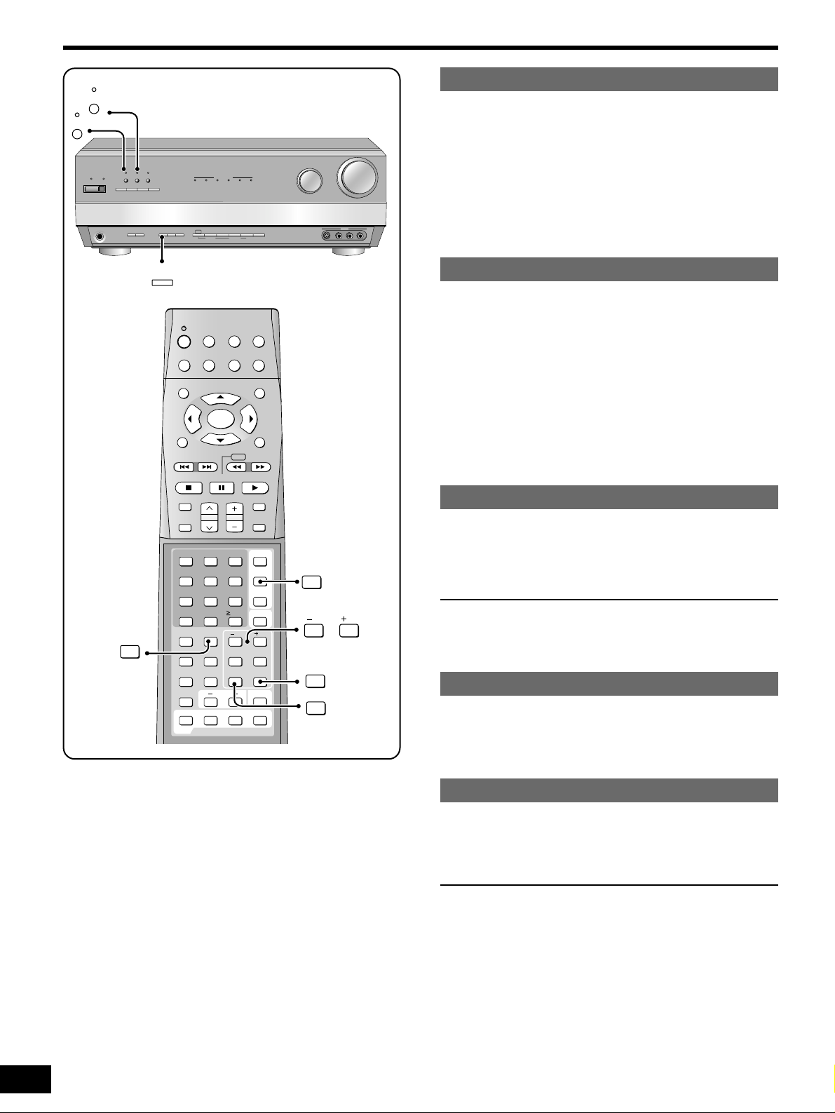
Other functions
Re-master
HQ sound mode
Input mode
Tone
Balance
Using 1/f algorithm technology, this original Panasonic feature
boosts the frequencies of the higher harmonics that are lost during
recording due to compression.
Press [RE-MASTER] to select “EFFECT 1”,
“EFFECT 2”, “EFFECT 3” or “EFFECT 4”.
When Re-master is on, the current level appears, then each time
you press the button:
EFFECT 1: for fast tracks (pop and rock)
EFFECT 2: for tracks with a variety of tempos (jazz)
EFFECT 3: for slow tracks (classical)
EFFECT 4: for compressed audio signals
OFF: the re-master processing is off.
HQ sound mode uses a system that varies the actual gain of the
amplifier. This helps provide clear sound when listening at regular
volume levels.
Press [HQ SOUND MODE].
For your reference
You can only raise the volume to –10 dB when HQ sound mode is
on and the level is automatically lowered to this level if you turn HQ
sound mode on when the level is higher.
This unit automatically detects whether input is digital or analogue,
but you can fix the input mode.
Press [INPUT MODE] to select “AUTO”, “ANALOG”
or “DIGITAL”.
For your reference
¡When input is DIGITAL
The tape monitor cannot be used.
You can adjust the level of the bass and treble.
11
Press [TONE] to select “BASS” or “TREBLE”.
22
Press [–/L] or [+/R] to adjust bass/treble.
For your reference
¡To adjust the tone
The STEREO DSP mode must be on and input must be either
analogue or PCM signals. You cannot adjust the tone while the
SOURCE DIRECT mode is on or if DVD 6CH INPUT is selected.
You can adjust the balance of the front speakers.
11
Press [BALANCE].
22
Press [–/L] or [+/R] to adjust.
DOLBY
DIGITAL
DOLBY
PRO LOGIC 2
DTS-ESDOLBY
DIGITAL EX
RE-MASTER
WAKE
8
^
SOURCE DIRECT
NEO:6
DSP
SOUND MODE
DOLBY
PRO LOGIC 2
HQ
SOUND MODE
ENHANCED
SURROUND
DTS
MULTI DECODER
NEO:6
INPUT SELECTOR
VOLUME
DOWN UP
A SPEAKERS B
PHONES
RDS
- BAND
–
FM MODE
MEMORY
DISPLAY
MODE
PTY SEARCH PTY SELECTOR
PRESET2 TUNING
1
INPUT
MODE
TAPE
MONITOR
DVD
6CH INPUT
VCR 3
S-VIDEO IN VIDEO IN
L AUDIO IN R
INPUT
MODE
RE-MASTER
HQ
SOUND MODE
INPUT
SELECTOR
SUBWOOFER
TV
TUNER/BAND
TOP MENU
MENU
RECEIVER
TAPEMD CD
VCR
DVD
RETURN
PAUSESTOP
SOUND MODE
CHANNEL VOLUME
PLAY
SLOW /SEARCH
SKIP
DISPLAY
MUTING
ENTER
3
6
2
5
1
4
987
0
DIRECT TUNING/
DISC
ENHANCED
SURROUND
DOLBY
PROLOGIC 2
SFC
RE-MASTER
TESTNEO:6
10/-/--
INPUT MODE
DVD 6CH
TIMER
LEVELEFFECT
/ L
/ R
TONE
BALANCE
DIMMER
SETUPPAGEAUDIO GROUP
DVD
TV/AV
TV VOL
SOURCE DIRECT
/ L
/ R
BALANCE
RE-MASTER
INPUT MODE
TONE
Page 19
19
RQT6252
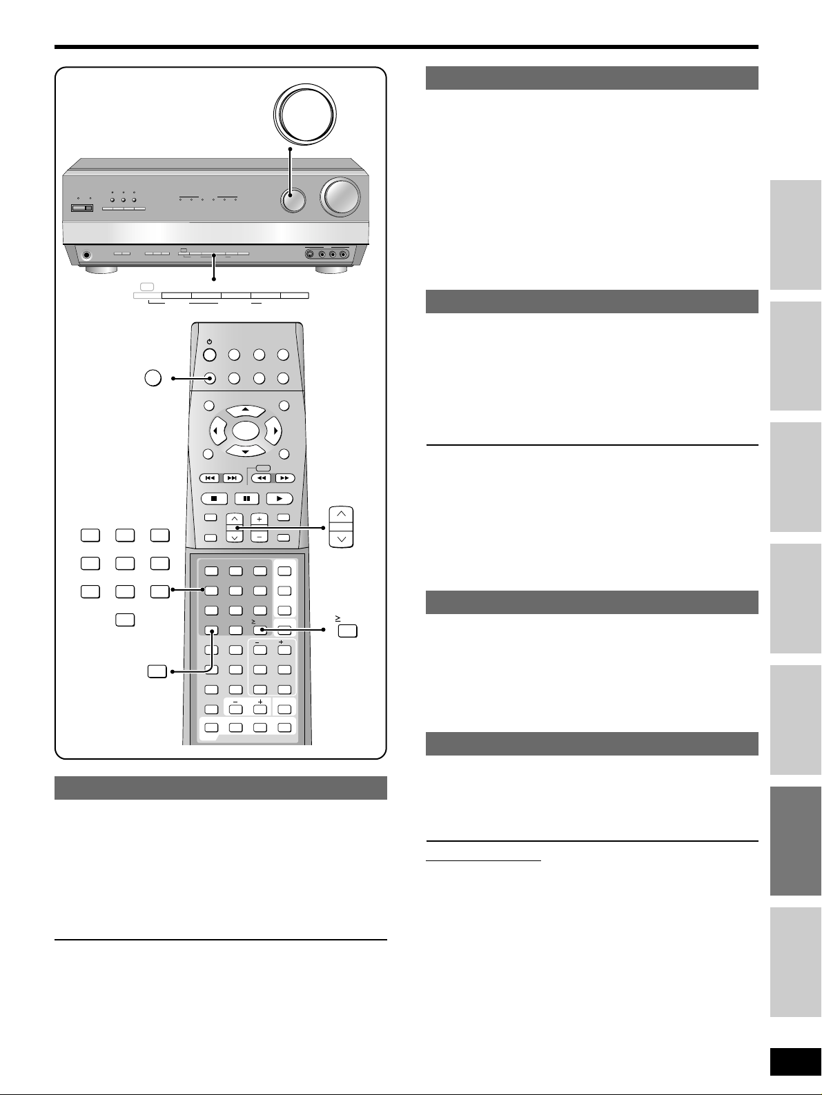
Preset the stations one at a time.
11
Tune to the station.
22
Press [MEMORY].
33
Press [TUNING, 2, 1, PTY SELECTOR] to
select a channel.
44
Press [MEMORY].
11
Tune to “FM 87.50 MHz”.
22
Press and hold [MEMORY].
The FM stations the unit can receive are preset in channels 1 to 30.
33
Tune to “AM 522 kHz”.
44
Press and hold [MEMORY].
The AM stations the unit can receive are preset in channels 21 to 30.
(FM stations are replaced if any were preset in these channels.)
During automatic presetting, the memory indicator (˜) flashes and
the frequency scrolls. The memory indicator and channel numbers
are displayed for a second when a station is preset.
The last station to be preset is displayed when presetting finishes.
For your reference
Even if the mains lead is disconnected from the household mains
socket, the stations remain in memory for approximately one month.
11
Press [PRESET, PTY SEARCH].
The channel number flashes for about 5 seconds.
22
Press [TUNING, 2, 1, PTY SELECTOR].
Hold down the buttons to change channels faster.
On the remote control
Press [CHANNEL 1 or 2 ].
or
Press the numbered buttons.
For channels 1 to 9, press the corresponding number.
For channels 10 or over, press [≥10/-/--], then the two digits.
e.g. To select channel 21: [≥10/-/--] / [2] / [1]
The radio
Step 1
Step 2
Step 3
Step 4
Before use
Others
Reference
Automatic presetting
Manual presetting
Selecting channels
Manual tuning
Direct tuning
You can tune radio stations manually by selecting the station’s
frequency.
11
Turn [INPUT SELECTOR] to select “TUNER”.
22
Press [-BAND, –FM MODE, DISPLAY MODE] to
select “FM” or “AM”.
33
Press [TUNING, 2, 1, PTY SELECTOR] to
select the frequency.
For your reference
Some equipment can interfere with radio reception. Turn off nearby
TV, VCR, DVD players, and satellite receivers or move them further
away from the antennas if this occurs.
qq
Press [TUNER/BAND RECEIVER].
The band changes each time you press the button.
ww
Press [DIRECT TUNING/DISC].
ee
Press the numbered buttons to enter the
frequency.
e.g. To select 107.90 MHz, press [1] / [0] / [7] / [9] / [0]
¡If you do not press a button while the cursor is flashing, the
display returns to the frequency being received.
¡If the frequency has not been input correctly, “ERROR” will be
displayed.
DOLBY
DIGITAL
DOLBY
PRO LOGIC 2
DTS-ESDOLBY
DIGITAL EX
RE-MASTER
WAKE
8
^
SOURCE DIRECT
NEO:6
DSP
SOUND MODE
DOLBY
PRO LOGIC 2
HQ
SOUND MODE
ENHANCED
SURROUND
DTS
MULTI DECODER
NEO:6
INPUT SELECTOR
VOLUME
DOWN UP
A SPEAKERS B
PHONES
RDS
- BAND
–
FM MODE
MEMORY
DISPLAY
MODE
PTY SEARCH PTY SELECTOR
PRESET2 TUNING
1
INPUT
MODE
TAPE
MONITOR
DVD
6CH INPUT
VCR 3
S-VIDEO IN VIDEO IN
L AUDIO IN R
INPUT SELECTOR
RDS
- BAND
– FM MODE
DISPLAY
MODE
MEMORY PRESET
PTY SEARCH PTY SELECTOR
2
TUNING
1
INPUT
SELECTOR
SUBWOOFER
TV
TUNER/BAND
TOP MENU
MENU
RECEIVER
TAPEMD CD
VCR
DVD
RETURN
PAUSESTOP
SOUND MODE
CHANNEL VOLUME
PLAY
SLOW /SEARCH
SKIP
DISPLAY
MUTING
ENTER
36251
4
987
0
DIRECT TUNING/
DISC
ENHANCED
SURROUND
DOLBY
PROLOGIC 2
SFC
RE-MASTER
TESTNEO:6
10/-/--
INPUT MODE
DVD 6CH
TIMER
SOURCE DIRECT
LEVELEFFECT
/ L
/ R
TONE
BALANCE
DIMMER
SETUPPAGE
AUDIO
GROUP
DVD
TV/AV
TV VOL
CHANNEL
TUNER/BAND
RECEIVER
3
6
2
5
1
4
987
0
DIRECT TUNING/
DISC
10/-/--
Page 20
20
RQT6252
RDS broadcasts
DOLBY
DIGITAL
DOLBY
PRO LOGIC 2
DTS-ESDOLBY
DIGITAL EX
RE-MASTER
WAKE
8
^
SOURCE DIRECT
NEO:6
DSP
SOUND MODE
DOLBY
PRO LOGIC 2
HQ
SOUND MODE
ENHANCED
SURROUND
DTS
MULTI DECODER
NEO:6
INPUT SELECTOR
VOLUME
DOWN UP
A SPEAKERS B
PHONES
RDS
- BAND
–
FM MODE
MEMORY
DISPLAY
MODE
PTY SEARCH PTY SELECTOR
PRESET2 TUNING
1
INPUT
MODE
TAPE
MONITOR
DVD
6CH INPUT
VCR 3
S-VIDEO IN VIDEO IN
L AUDIO IN R
RDS
- BAND
– FM MODE
DISPLAY
MODE
MEMORY PRESET
PTY SEARCH PTY SELECTOR
2
TUNING
1
RDS (Radio data system) is a multiplex broadcasting system to help
you enjoy radio more and tune into programs easier.
PS (Program service): Station name
PTY (Program type): Displays the program type, and is used to
search for a type of program from amongst
preset FM stations.
RT (Radio text): This unit can show up to 64 characters by scrolling
them across the display. The text could be about
the song, traffic and weather, phone in numbers, or
police information.
This unit does not have the emergency broadcast system (EBS)
that tunes automatically into emergency broadcasts.
Note
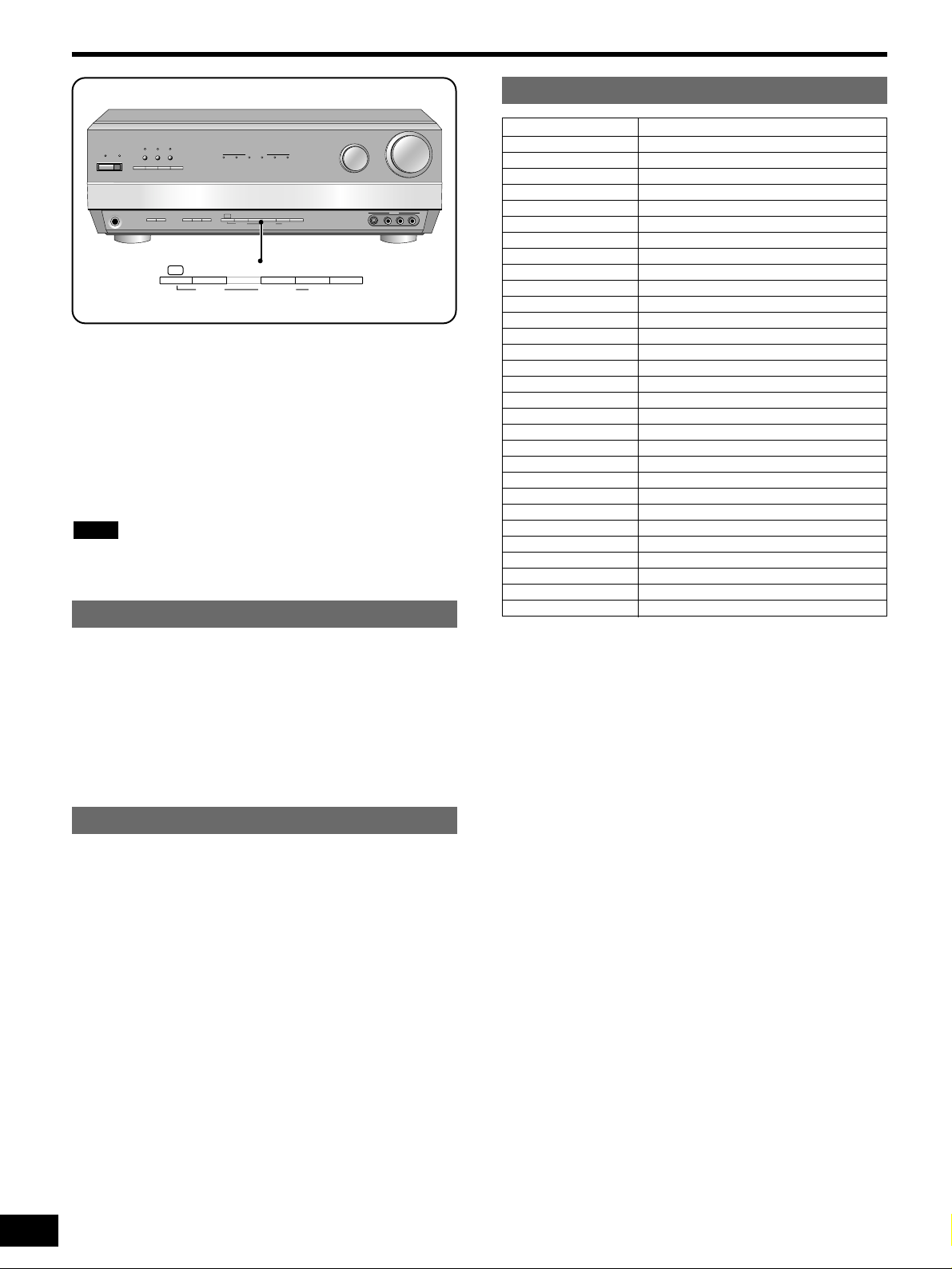
q Press [RDS].
w Press [-BAND, –FM MODE, DISPLAY MODE].
The display changes each time you press the button:
To display RDS information
First, preset FM stations.
q Press [RDS].
w While “RDS” is flashing
Press [TUNING, 2, 1, PTY SELECTOR] to
select the program type.
The display changes each time you press the button.
e While the PTY display is flashing
Press [PRESET, PTY SEARCH].
The PTY indicator flashes while searching.
The unit switches to the station broadcasting the program.
The PTY indicator flashes for another two seconds.
¡“SELECT PTY FIRST” is displayed if you try to start without
selecting a program type.
PTY search
PTY display: “NO PTY” appears if PTY signals are not being
received.
Frequency display
PS display PTY display RT display
./
..
./ ./
... ,...
NEWS
AFFAIRS
INFO
SPORT
EDUCATE
DRAMA
CULTURE
SCIENCE
VARIED
POP M
ROCK M
M. O. R. M
LIGHT M
CLASSICS
OTHER M
WEATHER
FINANCE
CHILDREN
SOCIAL A
RELIGION
PHONE IN
TRAVEL
LEISURE
JAZZ
COUNTRY
NATIONAL
OLDIES
FOLK M
DOCUMENT
TEST
ALARM
PTY displays
News
Current affairs
Information
Sport
Education
Drama
Culture
Science
Varied
Pop music
Rock music
Middle-of-the-road Music
Light classical
Serious classical
Other music
Weather information
Finance
Children
Social affairs
Religion
Phone in
Travel
Leisure
Jazz music
Country music
National music
Oldies
Folk music
Documentary
Test broadcast
Emergency announcement
Page 21
21
RQT6252
Change this setting to listen to software recorded with Dolby Digital
at low volume (such as late at night) and maintain audio clarity. It
reduces the peak level in loud scenes without affecting the sound
field.
OFF: The software is played with the original dynamic range
(factory setting).
STANDARD: The level recommended by the producer of the
software for household viewing.
MAX: The maximum allowable compression (recommended for
night viewing).
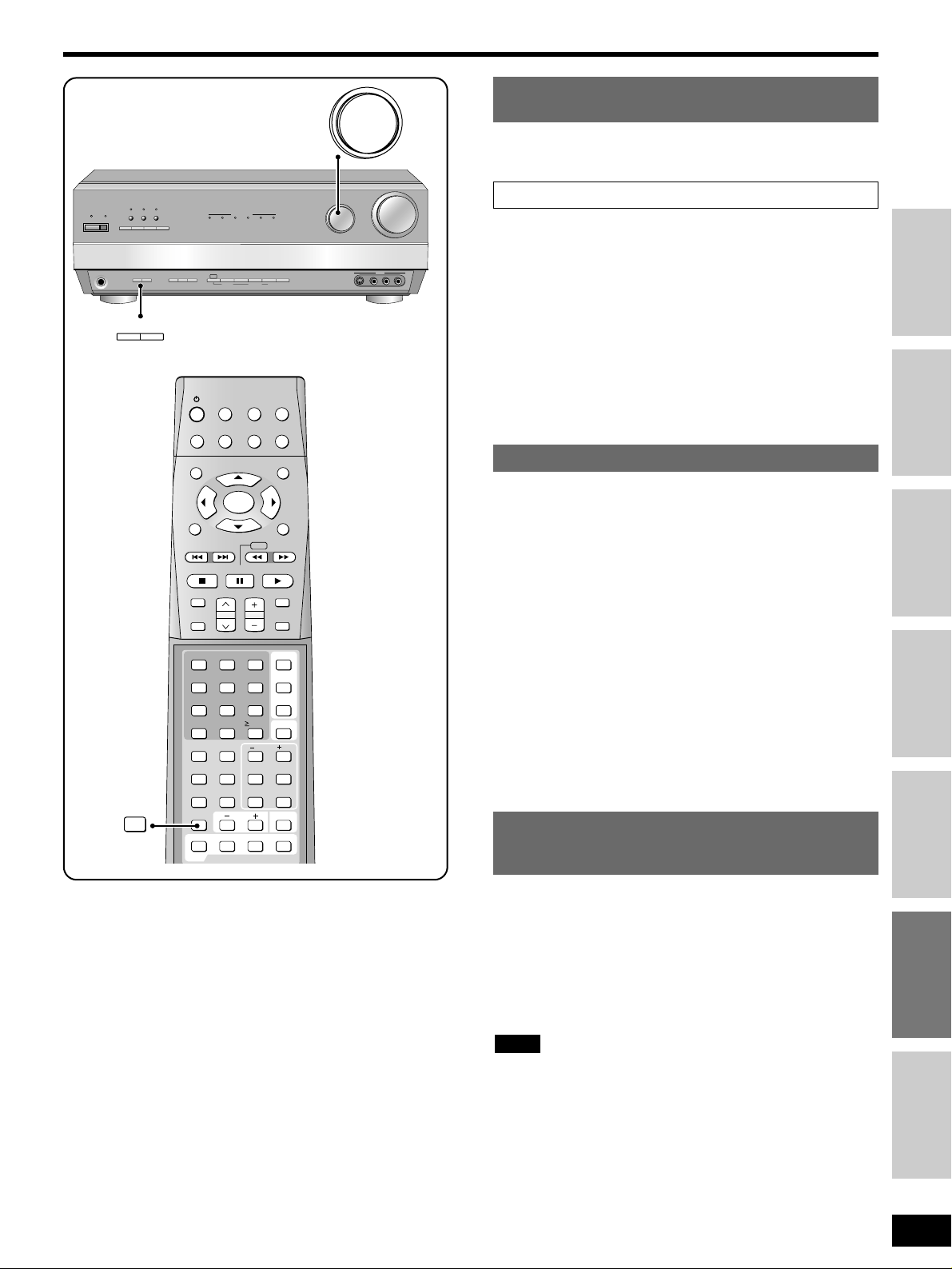
11
Press and hold [A] and [B] at the same time to
enter the setting mode.
22
Press [A] to select “DR COMP”.
33
Turn [INPUT SELECTOR] to select “OFF”,
“STANDARD” or “MAX”.
44
Press and hold [A] and [B] at the same time to
exit the setting mode.
Other settings
DR COMP –
Dynamic range compression
A/D ATT –
turn the A/D attenuator on if
“OVER” lights frequently when using 2-channel
analogue input
The factory setting is OFF.
11
Press and hold [A] and [B] at the same time to
enter the setting mode.
22
Press [A] to select “A/D ATT”.
33
Turn [INPUT SELECTOR] to select “OFF” or
“ON”.
44
Press and hold [A] and [B] at the same time to
exit the setting mode.
¡The setting affects all 2-channel analogue input.
¡You can raise the volume to a maximum of –10 dB while A/D
ATT is on.
Note
Step 1
Step 2
Step 3
Step 4
Before use
Others
Reference
DIMMER –
Dim the display for better viewing
in a darkened room
Choose a level between 1 (dim) and 5 (bright).
The factory setting is LEVEL 2.
11
Press and hold [A] and [B] at the same time to
enter the setting mode.
22
Press [A] to select “DIMMER”.
33
Turn [INPUT SELECTOR] to select “LEVEL 1”,
“LEVEL 2”, “LEVEL 3”, “LEVEL 4” or “LEVEL 5”.
The brightness changes to show the level.
44
Press and hold [A] and [B] at the same time to
exit the setting mode.
Adjusting the brightness of the display
Press [DIMMER] on the remote control.
^
WAKE
8
PHONES
ENHANCED
HQ
RE-MASTER
SOUND MODE
SURROUND
DSP
DOLBY
NEO:6
SOURCE DIRECT
SOUND MODE
PRO LOGIC 2
A SPEAKERS B
A SPEAKERS B
DIMMER
INPUT
TAPE
DVD
MONITOR
6CH INPUT
MODE
TUNER/BAND
RECEIVER
TOP MENU
DISPLAY
SOUND MODE
SUBWOOFER
4
DIRECT TUNING/
DISC
ENHANCED
SURROUND
DOLBY
PROLOGIC 2
DIMMER
DVD
MULTI DECODER
DOLBY
DOLBY
PRO LOGIC 2
DIGITAL EX
DIGITAL
- BAND
RDS
FM MODE
–
DISPLAY
MODE
TV
ENTER
SKIP
PAUSESTOP
CHANNEL VOLUME
251
0
RE-MASTER
SFC
TESTNEO:6
TV VOL
DTS-ESDOLBY
MEMORY
PRESET2 TUNING
PTY SEARCH PTY SELECTOR
VCR
TAPEMD CD
SLOW /SEARCH
3
6
987
10/-/--
/ L
TONE
DTS
NEO:6
DVD
MENU
PLAY
MUTING
INPUT
SELECTOR
SOURCE DIRECT
INPUT MODE
DVD 6CH
TIMER
LEVELEFFECT
BALANCE
TV/AV
SETUPPAGEAUDIO GROUP
1
RETURN
/ R
INPUT SELECTOR
S-VIDEO IN VIDEO IN
INPUT SELECTOR
DOWN UP
VCR 3
L AUDIO IN R
VOLUME
Page 22
22
RQT6252
You can record to a tape deck connected to TAPE REC (OUT), a
MD deck or CD recorder connected to MD/CD-R/RW REC (OUT), a
VCR connected to VCR 1 OUT, a DVD recorder/VCR connected to
DVR/VCR 2 OUT, or digital recording equipment connected to
DIGITAL OPTICAL OUT.
See the recording unit’s operating instructions for details on how to
prepare it for recording.
11
Turn [INPUT SELECTOR] to select the source to
be recorded.
22
Begin recording.
Follow your recording unit’s operating instructions.
33
Start the source to be recorded.
Follow your equipment’s operating instructions.
¡With a tape deck, you can record any analogue source except
TAPE.
¡With a MD deck or CD recorder, you can record any analogue
source except TAPE and MD/CD-R/RW.
¡With a VCR (connected VCR 1), you can record any analogue
source except TAPE and VCR 1.
¡With a DVD recorder/VCR (connected DVR/VCR2), you can
record any analogue source except TAPE and DVR/VCR2.
¡With digital recording equipment, you can record any digital
source without copy protection.
¡When you select DVD 6CH INPUT mode, only sound from the
front left and right channels is recorded.
¡Some sources do not allow digital recording. Connect through the
analogue terminals and select “ANALOG” input.
Note
Recording on other equipment
Making a recordingTimer function
DOLBY
DIGITAL
DOLBY
PRO LOGIC 2
DTS-ESDOLBY
DIGITAL EX
RE-MASTER
WAKE
8
^
SOURCE DIRECT
NEO:6
DSP
SOUND MODE
DOLBY
PRO LOGIC 2
HQ
SOUND MODE
ENHANCED
SURROUND
DTS
MULTI DECODER
NEO:6
INPUT SELECTOR
VOLUME
DOWN UP
A SPEAKERS B
PHONES
RDS
- BAND
–
FM MODE
MEMORY
DISPLAY
MODE
PTY SEARCH PTY SELECTOR
PRESET2 TUNING
1
INPUT
MODE
TAPE
MONITOR
DVD
6CH INPUT
VCR 3
S-VIDEO IN VIDEO IN
L AUDIO IN R
INPUT SELECTOR
DOLBY
DIGITAL
DOLBY
PRO LOGIC 2
DTS-ESDOLBY
DIGITAL EX
RE-MASTER
WAKE
WAKE
8
^
SOURCE DIRECT
NEO:6
DSP
SOUND MODE
DOLBY
PRO LOGIC 2
HQ
SOUND MODE
ENHANCED
SURROUND
DTS
MULTI DECODER
NEO:6
INPUT SELECTOR
VOLUME
DOWN UP
A SPEAKERS B
PHONES
RDS
- BAND
–
FM MODE
MEMORY
DISPLAY
MODE
PTY SEARCH PTY SELECTOR
PRESET2 TUNING
1
INPUT
MODE
TAPE
MONITOR
DVD
6CH INPUT
VCR 3
S-VIDEO IN VIDEO IN
L AUDIO IN R
3
6
2
5
1
4
987
0
DIRECT TUNING/
DISC
ENHANCED
SURROUND
DOLBY
PROLOGIC 2
SFC
RE-MASTER
TESTNEO:6
10/-/--
INPUT MODE
DVD 6CH
TIMER
LEVELEFFECT
/ L
/ R
TONE
BALANCE
DIMMER
SETUPPAGEAUDIO GROUP
TV/AV
TV VOL
TIMER
–/L +/R
SOURCE DIRECT
While the unit is on
While pressing and holding [DSP SOUND
MODE], press [8
], so “RESET” appears
on the display.
Settings are reset to those made at the time of shipment. Preset
radio stations remain intact.
DOLBY
DIGITAL
DOLBY
PRO LOGIC 2
DTS-ESDOLBY
DIGITAL EX
RE-MASTER
WAKE
8
^
SOURCE DIRECT
NEO:6
DSP
SOUND MODE
DOLBY
PRO LOGIC 2
HQ
SOUND MODE
ENHANCED
SURROUND
DTS
MULTI DECODER
NEO:6
INPUT SELECTOR
VOLUME
DOWN UP
A SPEAKERS B
PHONES
RDS
- BAND
–
FM MODE
MEMORY
DISPLAY
MODE
PTY SEARCH PTY SELECTOR
PRESET2 TUNING
1
INPUT
MODE
TAPE
MONITOR
DVD
6CH INPUT
VCR 3
S-VIDEO IN VIDEO IN
L AUDIO IN R
DSP
SOUND MODE
8
The SLEEP timer can turn the unit off after a set time and the
WAKE timer can turn it on. You can use only one timer at a time.
They do not control any other components.
qq
Press [TIMER].
“TIMER” is shown in the display.
ww
Within 4 seconds
Press [TIMER] to select the timer.
SLEEP / WAKE / OFF
ee
Within 5 seconds
Press [–/L] or [+/R] to select the required time.
The display changes as follows:
SLEEP (in minutes)
30 ,/ 60 ,/ 90 ,/ 120
WAKE (in hours)
5H ,/ 6H ,/ 7H ,/ 8H ,/ 9H ,/ 10H
¡ SLEEP starts working immediately.
¡ WAKE starts working when you switch the unit to standby.
(The “WAKE” timer indicator lights up.)
To check the setting
Press [TIMER] once.
¡If you set SLEEP, the time remaining appears.
¡If you set WAKE, the setting appears.
To change the setting
Repeat the procedure from the beginning.
/
The RESET function
Page 23

23
RQT6252
Troubleshooting guide
Before requesting service for this unit, check the chart below for a possible cause of the problem you are experiencing. Some simple checks or
a minor adjustment on your part may eliminate the problem and restore proper operation.
If you are in doubt about some of the check points, or if the remedies indicated in the chart do not solve the problem, consult your dealer for
instructions.
¡Connect the appropriate antenna. (You may need an outdoor antenna or one
with more elements.)
¡Adjust the position of the FM or AM antenna.
¡Reduce the treble.
¡Select “SOURCE DIRECT”.
¡Turn off nearby televisions, video decks, DVD players, and satellite receivers.
¡Separate the antenna from other cables, leads, and appliances.
¡Change the frequency step. Hold [-BAND, –FM MODE, DISPALY MODE]
down for 3 seconds to change the step to 9 kHz.
The radio cannot be tuned in or
there is a lot of noise and
interference.
The correct AM frequency cannot
be tuned in.
7
7
18
16
–
–
–
¡Ensure the SPEAKERS settings for your speakers are correct.
¡Check the DSP sound mode.
Sound is not heard from the
center, surround, or subwoofer
speakers.
10
16
¡Ensure the SPEAKERS settings for your speakers are correct.
¡Turn ENHANCED SURROUND on.
Sound is not heard from the
surround back speaker.
10
16
¡Turn DVD 6CH INPUT off.
¡The DSP switches to STEREO if input is PCM with sampling frequencies of
96 or 88.2 kHz.
DSP sound modes cannot be
selected.
12
16
DSP sound modes
Pages
Radio
Pages
Common problems
¡Ensure the AC mains lead is connected.
No power.
¡Switch off the unit, determine and correct the cause, then switch the unit on.
Causes include:
–Shorting (bare wires touching) of positive and negative speaker wires.
–Using speakers with an impedance lower than that rated for this unit.
–Straining of the speakers through excessive volume or power.
–Using the unit in a hot environment without proper ventilation.
Sound stops. “OVERLOAD”
appears on the display.
7
–
¡Turn the volume up.
¡Check connections to speakers and other equipment.
¡Turn on the speakers.
¡Turn off the tape monitor.
¡Select the correct source.
¡Change the D-INPUT setting to suit the type of connection you have made.
¡Check that the digital signals can be decoded by this unit.
¡Turn PCM FIX or DTS FIX off.
No sound.
13
4–9
12
13
12
11
16
16
8
9
–
–
¡Turn the unit off, disconnect the AC mains lead, and consult your dealer.
“F 70” appears on the display.
Pages
Step 1
Step 2
Step 3
Step 4
Before use
Others
Reference
Page 24
Specifications (DIN 45 500)
To clean this unit, wipe with a soft, dry cloth.
¡Never use alcohol, paint thinner or benzine to clean this unit.
¡Before using chemically treated cloth, read the instructions that
came with the cloth carefully.
If the surfaces are dirty
Maintenance
■ AMPLIFIER SECTION
Power output (at 230 V for continental Europe)
(at 240 V for the United Kingdom)
DIN 1 kHz (T.H.D. 1 %) 2 × 100 W (6 Ω)
20 Hz–20 kHz continuous power output
both channels driven 2 × 80 W (6 Ω)
Total harmonic distortion
rated power at 20 Hz–20 kHz 0.05 % (6 Ω)
half power at 1 kHz 0.03 % (6 Ω)
Power output each channel driven
DIN 1 kHz (T.H.D. 1 %)
Front (L/R) 100 W (6 Ω)
Center 100 W (6 Ω)
Surround (L/R/BACK) 100 W (6 Ω)
Power bandwidth
both channels driven, –3 dB 10 Hz –100 kHz (6 Ω, 0.9 %)
Damping factor 45 (6 Ω)
Load impedance
Front (L/R)
A or B 4–16 Ω
A and B 8–16 Ω
Center 6–16 Ω
Surround (L/R/BACK) 6–16 Ω
Frequency response
PHONO RIAA standard curve (30 Hz–15 kHz) ±0.8 dB
CD, MD/CD-R/RW, TV, DVD/DVD 6CH, VCR 1, DVR/VCR 2,
VCR 3, TAPE 10 Hz–100 kHz, ±3 dB
Input sensitivity and impedance
PHONO 3 mV/47 kΩ
CD, MD/CD-R/RW, TV, DVD/DVD 6CH, VCR 1, DVR/VCR 2,
VCR 3, TAPE 200 mV/22 kΩ
S/N at rated power (6 Ω)
PHONO 70 dB (IHF, A: 80 dB)
CD, MD/CD-R/RW, TV, DVD/DVD 6CH, VCR 1, DVR/VCR 2,
VCR 3, TAPE 98 dB (IHF, A: 100 dB)
SOURCE DIRECT/HQ SOUND MODE
108 dB, IHF A/Rated Power/S=2 V
Tone controls
BASS 50 Hz, +10 to –10 dB
TREBLE 20 kHz, +10 to –10 dB
Output voltage
TAPE, MD/CD-R/RW, VCR 1, DVR/VCR 2 200 mV
Channel balance (250 Hz–6.3 kHz) ±1 dB
Channel separation 55 dB
Headphones output level and impedance 430 mV/330 Ω
Subwoofer frequency response (–6 dB) 7–200 Hz
■ FM TUNER SECTION
Frequency range 87.50–108.00 MHz
Sensitivity
S/N 30 dB 1.5 µV/75 Ω
S/N 26 dB 1.3 µV/75 Ω
S/N 20 dB 1.2 µV/75 Ω
IHF usable sensitivity (IHF’58) 1.5 µV/75 Ω
IHF 46 dB stereo quieting sensitivity 22 µV/75 Ω
Total harmonic distortion
MONO 0.2 %
STEREO 0.3 %
S/N
MONO 60 dB (75 dB, IHF)
STEREO 58 dB (71 dB, IHF)
Frequency response
20 Hz–15 kHz +1 dB, –2 dB
Alternate channel selectivity
±400 kHz 65 dB
Capture ratio 1.5 dB
Image rejection at 98 MHz 40 dB
IF rejection at 98 MHz 70 dB
Spurious response rejection at 98 MHz 70 dB
AM suppression 50 dB
Stereo separation
1 kHz 40 dB
Carrier leak
19 kHz –30 dB (–35 dB, IHF)
38 kHz –50 dB (–55 dB, IHF)
Channel balance (250 Hz–6.3 kHz) ±1.5 dB
Limiting point 1.2 µV
Bandwidth
IF amplifier 180 kHz
FM demodulator 1000 kHz
Antenna terminal 75 Ω (unbalanced)
■ AM TUNER SECTION
Frequency range 522–1611 kHz (9 kHz steps)
530–1620 kHz (10 kHz steps)
Sensitivity 20 µV, 330 µV/m
Selectivity 55 dB
IF rejection 50 dB
■ VIDEO SECTION
Output voltage at 1 V input (unbalanced) 1±0.1 Vp-p
Maximum input voltage 1.5 Vp-p
Input/output impedance 75 Ω (unbalanced)
S-VIDEO input DVD/DVD 6CH, VCR 1, DVR/VCR 2, VCR 3, TV
S-VIDEO output VCR 1, DVR/VCR 2, TV MONITOR
■ GENERAL
Power supply
For continental Europe AC 230 V, 50 Hz
For the United Kingdom AC 230–240 V, 50 Hz
Power consumption 280 W
Dimensions (W × H × D) 430 × 158 × 377 mm
Mass 11.9 kg
Power consumption in standby mode: 2 W
Note:
1. Specifications are subject to change without notice.
Mass and dimensions are approximate.
2. Total harmonic distortion is measured by the digital spectrum
analyzer.
Digital input (OPTICAL) 4
(COAXIAL) 1
Digital output (OPTICAL) 1
En
RQT6252-B
H0402HM0
Matsushita Electric Industrial Co., Ltd.
Web Site: http://www.panasonic.co.jp/global/
 Loading...