

Panasonic Sa-ak785lm-k Service Manual

© Panasonic Corporation 2009. All rights reserved.
Unauth
orized copying and distribution is a violation
of law.
MEX0911001CE
CD Stereo System
Mode
Rev. 01
l No. SA-AK785LM-K
Product Color: (K)...Black Type
Notes: This model’s CD Mechanism Unit (CR14C). Please refer to the Original Service Manual
(Order No. MD0805031CE) for this CD Mechanism Unit.
Nota: El idioma original de este Manual de Servicio es en idioma inglés, sin embargo algunas notas aquí mencionadas serán escritas en español
para mejor descripción para Centros de Servicio de México.
SH-FX785
SB-AK785 SB-AK785SB-AK780 SB-AK780SA-AK785

TABLE OF CONTENTS
1 Safety Precautions
1.1. G
eneral Guidelines
1.3. C
aution For Fuse Replacement
1.4. B
efore Repair and Adjustment
1.5. P
rotection Circuitry
1.6. S
afety Parts Information
2 Warning
2.1. Prevention of Electrostatic Dis
charge (ESD)
to E
lectrostatic Sensitive (ES) Devices
2.2. P
recaution of Laser Diode
2.3. Service caut
ion based on Legal restrictions
2.4. H
andling Precautions for Traverse Unit
3 Service Navi
gation
3.1. S
ervice Information
4 Spec
ifications
5 L
ocation of Controls and Components
5.1. Main U
nit Key Button Operation
5.2. R
emote Control Key Button Operation
5.3. D
isc Information
6 Self
-Diagnosis and Special Mode Setting
6.1. D
octor Mode Summary Table
6.2. D
octor Mode Table
6.3. S
ervice Mode Summary Table
6.4. S
ervice Mode Table
6.5. Reli
ability Test Mode (CD Mechanism Unit
CR14C)
6
.6. E
rror Code Table
7 Tr
oubleshooting Guide
7.1. Ju
piter USB
7.2. Troubleshooti
ng Guide
7.3. Troubleshoot
ing Guide for F61 and/or F76
8 Serv
ice Fixture & Tools
8.1. Service Tools and
Equipment
9 Dis
assembly and Assembly Instructions
9.1. D
isassembly Flow Chart
9.2. Main
Components and P.C.B. Locations
9.3. D
isassembly of Top Cabinet
9.4. Disassembly of
CD Mechanism Unit (CR14C)
9.5. D
isassembly of Rear Panel
9.6. D
isassembly of Fan Unit
9.7. D
isassembly of Front Panel Assembly
9.8. D
isassembly of Mic P.C.B.
9.9. D
isassembly of Panel P.C.B.
9.1
0. Disassembly of Dynamic Bass Knob &
Dyn
amic Bass Button Unit
9.11. Disassembly o
f Memory P.C.B.
9.1
2. Disassembly of MPort/Headphone P.C.B.
9.1
3. Disassembly of CD Servo P.C.B.
9.1
4. Disassembly of D-Amp P.C.B. & Fan
9.1
5. Replacement of Audio Digital Amp IC
(IC5400)
9.1
6. Replacement of Audio Digital Amp IC
(IC5000)
9.1
7. Replacement of Audio Digital Amp IC
(IC5200)
9.1
8. Disassembly of Main P.C.B.
9.1
9. Disassembly of SMPS P.C.B.
9.20. Replacement of Switching Regulator IC
9.21. Re
placement of Rectifier Diode (D5702)
9.22. Re
placement of Regulator Diode (D5801)
9.23. Re
placement of Regulator Diode (D5802)
9.24. Re
placement of Regulator Diode (D5803)
9.25. Disassembly of
AC Inlet P.C.B.
9.26. Disassembly of
Jupiter P.C.B.
9.27. Re
placement of Traverse Unit Assembly
9.28. Disassembly of
CD Lid
10 Service Position
10.
1. Checking and Repairing of Main P.C.B.
10.2. Ch
ecking and Repairing of Panel P.C.B., MIC
P.C.B
., Jupiter P.C.B. and MPort/Headphone
P.C.B.
10.
3. Checking and Repairing of D-Amp P.C.B.
10.
4. Checking and Repairing of SMPS P.C.B. and
AC Inlet P.C.B.
11 Vo
ltage & Waveform Chart
11.1. CD Servo P.C.B.
11.
2. Main P.C.B. (1/3)
11.
3. Main P.C.B. (2/3)
11.
4. Main P.C.B. (3/3)
11.
5. Panel P.C.B.
11.6. D-Amp P.C.B.
11.
7. Jupiter P.C.B. (1/2)
11.
8. Jupiter P.C.B. (2/2)
11.9. Mic P.C.B.
11.10. SMPS P.C.B.
11.11. Waveform Table (
1/3)
11.12. Waveform Table (
2/3)
11.13. Waveform Table (
3/3)
12 Ill
ustration of ICs, Transistor and Diode
13 Bloc
k Diagram
13.
1. CD Servo Block Diagram
13.
2. Jupiter Block Diagram
13.
3. Main(1/2) Block Diagram
13.
4. Main(2/2) Block Diagram
13.5. Panel / MPort/He
adphone / Mic / Memory
Block D
iagram
13.
6. D-Amp Block Diagram
13.
7. SMPS / AC Inlet Diagram
14 Wiring Conne
ction Diagram
15 Schematic Diagram Notes
16 Schematic Diagram
16.1. CD Servo Circuit
16.
2. Main Circuit (1/6)
16.
3. Main Circuit (2/6)
16.
4. Main Circuit (3/6)
16.
5. Main Circuit (4/6)
16.
6. Main Circuit (5/6)
16.
7. Main Circuit (6/6)
16.
8. Panel Circuit (1/2)
16.
9. Panel Circuit (2/2)
16.10. Memory / MPort/H
eadphone / Mic Circuit

16.11. D-Amp Circuit (1/2)
16.12. D-
16.13. Jupite
16.14. Jupite
16.15. Jupite
16.16. Jupite
16.17. SMP
16.18. SMP
16.19. AC
17 Printed Circu
17.
17.2. Main P.C.B.
17.
17.
17.
18 Termi
18.
18.
19 Exp
19.
19.
Amp Circuit (2/2)
r Circuit (1/4)
r Circuit (2/4)
r Circuit (3/4)
r Circuit (4/4)
S Circuit (1/2)
S Circuit (2/2
Inlet Circuit
it Board
1. CD Servo / Jupiter P.C.B.
3. Panel / Memory / MPort/Headphone / Mic
P.C.B.
4. D-Amp P.C.B.
5. SMPS/ AC Inlet P.C.B.
nal Function of ICs
1. IC2801 (MN101EF16KXW): IC
Microprocessor
2. IC6601(C0HBB0000057): IC FL Driver
loded View and Replacement Parts List
1. Exploded View and Mechanical Replacement
Parts List
2. Electrical Replacement Part List

4
1 Safety Precautions
1.1. General Guidelines
1. When servicing, observe the original lead dress. If a short circuit is found, replace all parts which have been overheated or
damaged by the short circuit.
2. After servicing, see to it that all the protective devices such as insulation barriers, insulation papers shields are properly
installed.
3. After servicing, carry out the following leakage current checks to prevent the customer from being exposed to shock hazards.
1.1.1. Leakage Current Cold Check
1. Unplug the AC cord and connect a jumper between the two prongs on the plug.
2. Measure the resistance value, with an ohmmeter, between the jumpered AC plug and each exposed metallic cabinet part on
the equipment such as screwheads, connectors, control shafts, etc. When the exposed metallic part has a return path to the
chassis, the reading should be between 1MΩ and 5.2MΩ.
When the exposed metal does not have a return path to the chassis, the reading must be
1.1.2. Leakage Current Hot Check
1. Plug the AC cord directly into the AC outlet. Do not use an isolation transformer for this check.
2. Connect a 1.5kΩ, 10 watts resistor, in parallel with a 0.15μF capacitors, between each exposed metallic part on the set and a
good earth ground such as a water pipe, as shown in Figure 1.
3. Use an AC voltmeter, with 1000 ohms/volt or more sensitivity, to measure the potential across the resistor.
4. Check each exposed metallic part, and measure the voltage at each point.
5. Reverse the AC plug in the AC outlet and repeat each of the above measurements.
6. The potential at any point should not exceed 0.75 volts RMS. A leakage current tester (Simpson Model 229 or equivalent)
may be used to make the hot checks, leakage current must not exceed 1/2 milliamp. In case a measurement is outside of the
limits specified, there is a possibility of a shock hazard, and the equipment should be repaired and rechecked before it is
returned to the customer.
Figure 1
1.2. Before Use (For PH only)
Be sure to disconnect the mains cord before adjusting the voltage selector.
Use a minus(-) screwdriver to set the voltage selector (on the rear panel) to the voltage setting for the area in which the unit will be
used. (If the power supply in your area is 110V ~ 127V or 220V ~ 240V, set to the “110V ~ 127V or 220V ~ 240V” position.)
Note that this unit will be seriously damaged if this setting is not made correctly. (There is no voltage selector for some countries,
the correct voltage is already set.)
1.3. Caution For Fuse Replacement
1.4. Before Repair and Adjustment
K
Ó
Disconnect AC power to discharge unit AC Capacitors as such (C5700, C5701, C5703, C5704, C5705, C5706, C5707) through a
10 ? , 10 W resistor to ground.
C
aution:
DO NOT SHORT-CIRCUIT DIRECTLY (with a screwdriver blade, for instance), as this may destroy solid state devices.
After repairs are completed, restore power gradually using a variac, to avoid overcurrent.
Cur
rent consumption at AC 110V~127V / 220V~240V, 50/60 Hz in NO SIGNAL mode volume minimal should be ~ 500 mA (For PH
only).
Cur
rent consumption at AC 120V, 60 Hz in NO SIGNAL mode volume minimal should be ~ 500 mA (For PN only).
1.5. Protection Circuitry
The protection circuitry may have operated if either of the following conditions are noticed:
• No sound is hea
• Sound stops during a p
The function of this circu
rd when the power is turned on.
erformance.
itry is to prevent circuitry damage if, for example, the positive and negative speaker connection wires are
“shorted”, or if speaker systems with an impedance less than the indicated rated impedance of the amplifier are used.
If this occur
s, follow the procedure outlines below:
1. Turn off the power.
2. Determine the cause of the p
roblem and correct it.
3. Turn on the power once again after one minute.
Note:
When the protection circuitry functions, the unit will not op
erate unless the power is first turned off and then on again.
1.6. Safety Parts Information
Safety Parts List:
There are special components used in this equipment which are important for safety.
hese parts are marked by in the Schematic Diagrams & Replacement Parts List. It is essen
T
should be r
eplaced with manufacturer’s specified parts to prevent shock, fire or other hazards. Do not modify the original design
without permission of manufacturer.
Modelo:
SC-AK785LM-
tial that these critical parts
Safety
Nombre del componente
CABLE TOMACORRIENTE.
CONECTOR TOMACORRIENTE
TRANSFORMADOR DE PODER
TRANSFORMADOR DE
FUSIBLE PRIMARIO
CAPACITOR DE AC
CAPACITOR DE A
CAPACITOR DE AC
OPTOACOPLADOR
RESISTENCIA FUSIBLE
GAB. MET. SIN DOBLAR
LECTOR
RESPALDO
PCB SMPS
PTICO
(CD UNIT)
REAR PANEL
Numero de Parte
SJA168-1A
K2AA2B000017
ETS48AB12GAC
ETS19AB256AG
K5D802APA008
F0CAF334A087
C F1BAF1020020
F0CAF224A085
B3PBA0000402
RJBX0562T-1
K5G4013A0001
RKMX0144Z-KL
RD-DAC060-PX
RGRX0070R-AL
INSTRUCTIVO RQTM0171
BOBINA PRIMARIO ELF22V035B
SMPS FX785 N0AE6GY00001

7
2 Warning
2.1. Prevention of Electrostatic Discharge (ESD) to Electrostatic Sensitive
(ES) Devices
Some semiconductor (solid state) devices can be damaged easily by static electricity. Such components commonly are called Electrostatically Sensitive (ES) Devices. Examples of typical ES devices are integrated circuits and some field-effect transistors and
semiconductor "chip" components. The following techniques should be used to help reduce the incidence of component damage
caused by electrostatic discharge (ESD).
1. Immediately before handling any semiconductor component or semiconductor-equipped assembly, drain off any ESD on your
body by touching a known earth ground. Alternatively, obtain and wear a commercially available discharging ESD wrist strap,
which should be removed for potential shock reasons prior to applying power to the unit under test.
2. After removing an electrical assembly equipped with ES devices, place the assembly on a conductive surface such as aluminum foil, to prevent electrostatic charge buildup or exposure of the assembly.
3. Use only a grounded-tip soldering iron to solder or unsolder ES devices.
4. Use only an anti-static solder removal device. Some solder removal devices not classified as “anti-static (ESD protected)” can
generate electrical charge sufficient to damage ES devices.
5. Do not use freon-propelled chemicals. These can generate electrical charges sufficient to damage ES devices.
6. Do not remove a replacement ES device from its protective package until immediately before you are ready to install it. (Most
replacement ES devices are packaged with leads electrically shorted together by conductive foam, aluminum foil or comparable conductive material).
7. Immediately before removing the protective material from the leads of a replacement ES device, touch the protective material
to the chassis or circuit assembly into which the device will be installed.
Caution:
Be sure no power is applied to the chassis or circuit, and observe all other safety precautions.
8. Minimize bodily motions when handling unpackaged replacement ES devices. (Otherwise harmless motion such as the
brushing together of your clothes fabric or the lifting of your foot from a carpeted floor can generate static electricity (ESD) suf-
ficient to damage an ES device).

8
2.2. Precaution of Laser Diode
Caution:
This product utilizes a laser diode with the unit turned “on”, invisible laser radiation is emitted from the pickup lens.
Wavelength: 795 nm (CD)
Maximum output radiation power from pickup: 100 μW/VDE
Laser radiation from the pickup unit is safety level, but be sure the followings:
1. Do not disassemble the pickup unit, since radiation from exposed laser diode is dangerous.
2. Do not adjust the variable resistor on the pickup unit. It was already adjusted.
3. Do not look at the focus lens using optical instruments.
4. Recommend not to look at pickup lens for a long time.

9
2.3. Service caution based on Legal restrictions
2.3.1. General description about Lead Free Solder (PbF)
The lead free solder has been used in the mounting process of all electrical components on the printed circuit boards used for this
equipment in considering the globally environmental conservation.
The normal solder is the alloy of tin (Sn) and lead (Pb). On the other hand, the lead free solder is the alloy mainly consists of tin
(Sn), silver (Ag) and Copper (Cu), and the melting point of the lead free solder is higher approx.30 degrees C (86°F) more than that
of the normal solder.
Definition of PCB Lead Free Solder being used
Service caution for repair work using Lead Free Solder (PbF)
• The lead free solder has to be used when repairing the equipment for which the lead free solder is used.
(Definition: The letter of “PbF” is printed on the PCB using the lead free solder.)
• To put lead free solder, it should be well molten and mixed with the original lead free solder.
• Remove the remaining lead free solder on the PCB cleanly for soldering of the new IC.
• Since the melting point of the lead free solder is higher than that of the normal lead solder, it takes the longer time to melt the
lead free solder.
• Use the soldering iron (more than 70W) equipped with the temperature control after setting the temperature at 350±30 degrees
C (662±86°F).
Recommended Lead Free Solder (Service Parts Route.)
• The following 3 types of lead free solder are available through the service parts route.
RFKZ03D01K-----------(0.3mm 100g Reel)
RFKZ06D01K-----------(0.6mm 100g Reel)
RFKZ10D01K-----------(1.0mm 100g Reel)
Note
* Ingredient: tin (Sn), 96.5%, silver (Ag) 3.0%, Copper (Cu) 0.5%, Cobalt (Co) / Germanium (Ge) 0.1 to 0.3%
The letter of “PbF” is printed either foil side or components side on the PCB using the lead free solder.
(See right figure)

10
2.4. Handling Precautions for Traverse Unit
The laser diode in the optical pickup unit may break down due to static electricity of clothes or human body. Special care must be
taken avoid caution to electrostatic breakdown when servicing and handling the laser diode in the traverse unit.
2.4.1. Cautions to Be Taken in Handling the Optical Pickup Unit
The laser diode in the optical pickup unit may be damaged due to electrostatic discharge generating from clothes or human body.
Special care must be taken avoid caution to electrostatic discharge damage when servicing the laser diode.
1. Do not give a considerable shock to the optical pickup unit as it has an extremely high-precise structure.
2. To prevent the laser diode from the electrostatic discharge damage, the flexible cable of the optical pickup unit removed
should be short-circuited with a short pin or a clip.
3. The flexible cable may be cut off if an excessive force is applied to it. Use caution when handling the flexible cable.
4. The antistatic FPC is connected to the new optical pickup unit. After replacing the optical pickup unit and connecting the flexible cable, cut off the antistatic FPC.
2.4.2. Grounding for electrostatic breakdown prevention
Some devices such as the DVD player use the optical pickup (laser diode) and the optical pickup will be damaged by static electricity in the working environment. Proceed servicing works under the working environment where grounding works is completed.
2.4.2.1. Worktable grounding
1. Put a conductive material (sheet) or iron sheet on the area where the optical pickup is placed, and ground the sheet.
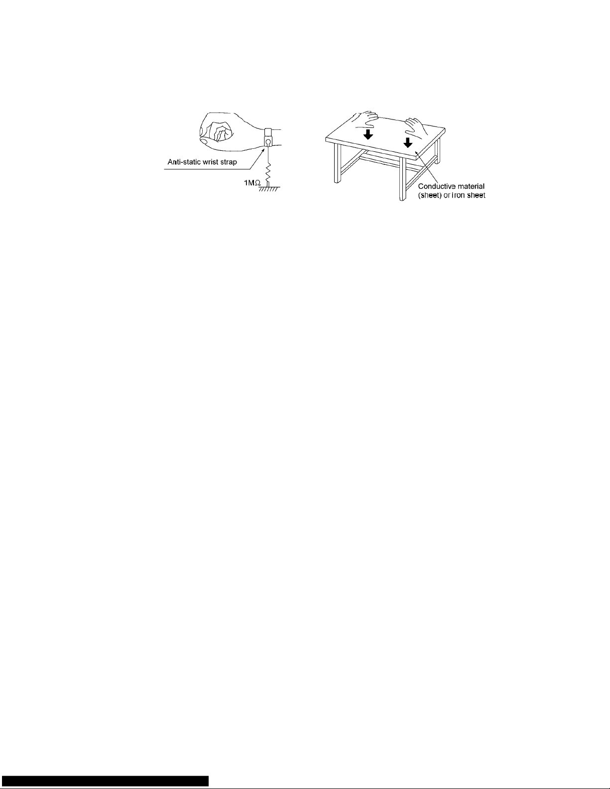
11
2.4.2.2. Human body grounding
1. Use the anti-static wrist strap to discharge the static electricity form your body.

3 Service Navigation
3.1. Service Information
This service manual contains technical information which will allow service personnel’s to understand and service this model.
Please place order
he circuit is changed or modified, this information will be followed by supplement service manual to be filed with original service
If t
ma
nual.
• CD Mechanism unit (CR14C):
s using the parts list and not the drawing reference numbers.
1) This model uses CD Mechanism Unit
his service manual does not contain the following information on CD Mechanism Unit (CR14C)
2) T
- Schematic Diagram, Block Diagram an
- P
arts List for individual parts of CD Mechanism Unit (CR14C).
- Exp
Please r
• Micro-processor, EEPROM:
1) T
- E
Before replacement of micro-processor IC, please check the version no. It may need matching with ROM correction.
• Spe
1) T
loded View and Part List for individual parts of CD Mechanism Unit (CR14C).
efer to original service manual (Order No. MD0805031CE)
he following components are supplied as an assembled part.
- Micro-processor IC, IC2801 (MN101EF16KXW) * este material debe ser grabado.
EPROM IC, IC2200 (C3EBFY000006)
aker system:
he information, please refer to original service manual, SB-AK780 & SB-WAK780.
(CR14C).
d P.C.B. layout of CD Mechanism Unit (CR14C) P.C.B.

4 Specifications
Especificaciones
SECCIÓN DEL AMPLIFICADOR
AK780 AK785
Modo estéreo de potencia de salida RMS
Canal delantero (ambos canales controlados)
Canal de subwoofer
Potencial total del modo estéreo RMS
Potencia de salida PMPO
AK580
250 W por canal (6 Ω ), 1 kHz,
250 W por canal (6 Ω ),100 Hz,
750 W
8300 W
Modo estéreo de potencia de salida RMS
Canal delantero (ambos canales controlados)
Potencial total del modo estéreo RMS
Potencia de salida PMPO
250 W por canal(6 Ω), 1 kHz
500 W
5500 W
SECCIÓN DEL SINTONIZADOR DE FM/AM,
TERMINALES
Emisoras presintonizadas
15 emisoras de AM
Modulación de frecuencia (FM)
Gama de frecuencias
87,9 MHz a 107,9 MHz (en pasos de 200 kHz)
87,5 MHz a 108,0 MHz (en pasos de 100 kHz)
Terminal(es) de la antena 75 Ω (desbalanceado)
Modulación de amplitud (AM)
Gama de frecuencias
520 a 1710 kHz (en pasos de 10 kHz)
Entrada AUX
Toma puerto de música (delantero)
Sensibilidad 100 mV, 4,7 k Ω
Terminal
Toma de auriculares
Terminal Estéreo, toma de 3,5 mm
Nivel de salida (CD, 1 kHz, –20 dB) 32 Ω (Máx.)
Toma de micrófono
Sensibilidad 0,7 mV, 1,2 k Ω
Terminal Mono, toma de 3,5 mm (1 si
30 emisoras de FM
Clavija jack RCA
Estéreo, toma de 3,5 mm
stema)
SECCIÓN DE DISCOS COMPACTOS
Discos reproducidos (8 cm ó 12 cm)
(1) CD-Audio (CD-DA)
(2) CD-R/RW (CD-DA, disco formateado con MP3
*
(3) MP3
*
MPEG-1 Layer 3, MPEG-2 Layer 3
Lector
Longitud de onda 795 nm
Salida de audio (Disco)
Número de canales
AK780 AK785
AK580
FL = Canal frontal izquierdo
FR = Canal frontal derecho
SW = Canal de subwoofer
*
)
2,1 (FL, FR, SW)
2 (FL, FR)
SECCIÓN DE USB
Puerto USB
Estándar USB USB 2,0 velocidad total
Soporte de formato de archivos de medios MP3 (
Sistema de archivo de dispositivo USB FAT 12, FAT 16, FAT 32
Corriente puerto USB
Velocidad de bits
16 kbps a 320 kbps (P.B)
500 mA (Máx.)
*
.mp3)
Grabación en el USB
Formato de archivo de grabación MP3 (
Velocidad de bits
Velocidad de grabación USB 1x, máx. 4x (CD solamente)
128 kbps / 192 kbps / 320 kbps
*
.mp3)
SECCIÓN DE BAFLES
Bafles frontales (SB-AK780)
Tipo
Sistema de 2 altavoces de 2 vías (Refl ejo de sonidos graves)
Bafle(s)
Altavoz para agudos Tipo cónico de 6 cm
Altavoz para graves
Impedancia
Potencia de entrada (IEC)
Presión acústica de salida
Gama de frecuencias
Dimensiones (AnxAlxPrf)
Peso
5,0 kg
Subwoofer (SB-WAK780)
Tipo Sistema de 1 altavoz de 1 vía (Refl ejo de sonidos graves)
Bafle(s)
Altavoz para graves
Impedancia 6 Ω
Potencia de entrada (IEC) 250W (Máx.)
Presión acústica de salida 82 dB/W (1,0 m)
Gama de frecuencias 48 Hz a 250 Hz (–16 dB)
Dimensiones (AnxAlxPrf) 320 mm x 414 mm x 327 mm
Peso 7,0 kg
Bafles para Sistema Inalámbrico (SB-AK785)
Tipo
Sistema de 2 altavoces de 2 vías (Refl ejo de sonidos graves)
Bafle(s)
Altavoz para agudos Tipo cónico de 6 cm
Altavoz para graves
Impedancia
Potencia de entrada (IEC)
Presión acústica de salida
Gama de frecuencias
Dimensiones (AnxAlxPrf)
Peso
5,0 kg
Tipo cónico de 20 cm
6 Ω
250 W (Máx.)
87 dB/W (1,0 m)
49 Hz a 21 kHz (–16 dB)
68 Hz a 20 kHz (–10 dB)
250 mm x 414 mm x 298 mm
AK780 AK785
Tipo cónico de 25 cm
50 Hz a 200 Hz (–10 dB)
AK785
Tipo cónico de 20 cm
125 W (Máx.)
87 dB/W (1,0 m)
49 Hz a 21 kHz (–16 dB)
68 Hz a 20 kHz (–10 dB)
250 mm x 414 mm x 298 mm
GENERALIDADES
Alimentación
Consumo
Dimensiones (AnxAlxPrf)
Peso
4,6 kg
Gama de temperaturas de funcionamiento
Gama de humedades de funcionamiento
Consumo en el modo de espera: 0.3 W (aproximado)
Nota:
1) Las especifi caciones están sujetas a cambios sin previo aviso.
La masa y las dime
2) La distorsión armónica t
espec tro d
127 V ~ 60 Hz
AK785AK780
AK580
250 mm x 333 mm x 326 mm
35% a 80% humedad relativa (sin condensación)
nsiones son aproximados.
otal se mide con el analizador de
igital.
: 145 W
: 112 W
0°C a +40°C
3 Ω

Especificaciones
SECCIÓN DE SISTEMA INALÁMBRICO (SH-FX785)
AK785
Modo estéreo de potencia de salida RMS
Canal delantero (ambos canales controlados)
125 W por canal (3 Ω), 1 kHz,
Potencial total del modo estéreo RMS 250 W
Potencia de salida PMPO 2700 W
GENERALIDADES
Alimentación 127 V ~ 60 Hz
Consumo
Dimensiones (AnxAlxPrf) Transmisor 65 mm x 20 mm x 105 mm
Peso Transmisor 0,03 kg
Dimensiones (AnxAlxPrf) Receptor 165 mm x 90 mm x 164 mm
Peso Receptor 0,7 kg
Velocidad de bits 1 kbps
Receptor SH-FX785RM
Rango de frecuencia 2,400 a 2,4835 GHz
Número de canales 3 canales
Gama de temperaturas de funcionamiento
Gama de humedades de funcionamiento
5% a 90% humedad relativa (sin condensación)
Consumo en el modo de espera: 0,2 W (aproximado)
+5 °C to +35 °C (+41 °F to +95 °F)
: 45 W
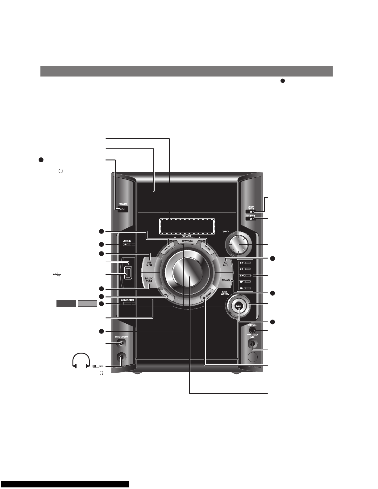
5 Location of Controls and Components
5.1. Main Unit Key Button Operation
Aparato principalAparato principal
Refiérase a los números entre paréntesis para la página de referencia. Los botones con etiquetas tales como funcionan de la misma
forma que los contro
Panel de visualización (10)
les del control remoto ( página 8).
1
Bandejas de d
Interruptor de alimentación
1
en espera/encendido
[ /
l, POWER] (6, 22)
Pulse este interruptor
para cambiar del modo de
modo de espera
y viceversa. En el
modo de espera,
el aparato consume
una pequeña cantidad de
Indicador de grabación
Puerto USB (12)
Sensor de señal de control
Toma puerto de música (17)
isco
encendido al
corriente.
USB (13)
AK785AK780
remoto
Abrir o cerrar bandeja de
d
isco (6, 9)
Cambio de d
10
6
2
3
9
11
Fun
ción saltar pista (9, 12)
8
Reproducción directa de
d
isco (9)
7
onfigurac
C
de soni
ecualiza
isco (9)
ión de control
dos graves de
dor manual (16)
5
Cont
4
rol de volumen del
rófono (16)
mic
Conector del m
(16)
icrófono
Toma de auriculares ( )
Procure evitar utilizarlos
iempo con el fi n de
mucho t
evitar lesiones auditivas.
La presión excesiva de los
auriculares puede causar
pérdida de au
Tipo de clavi
estéreo de Ø 3,5 mm
(no suministr
dición.
ja:
ada)
tención de la
De
reproducció
nción de demostración
Fu
(6)
Cont
n,
rol de volumen (16)
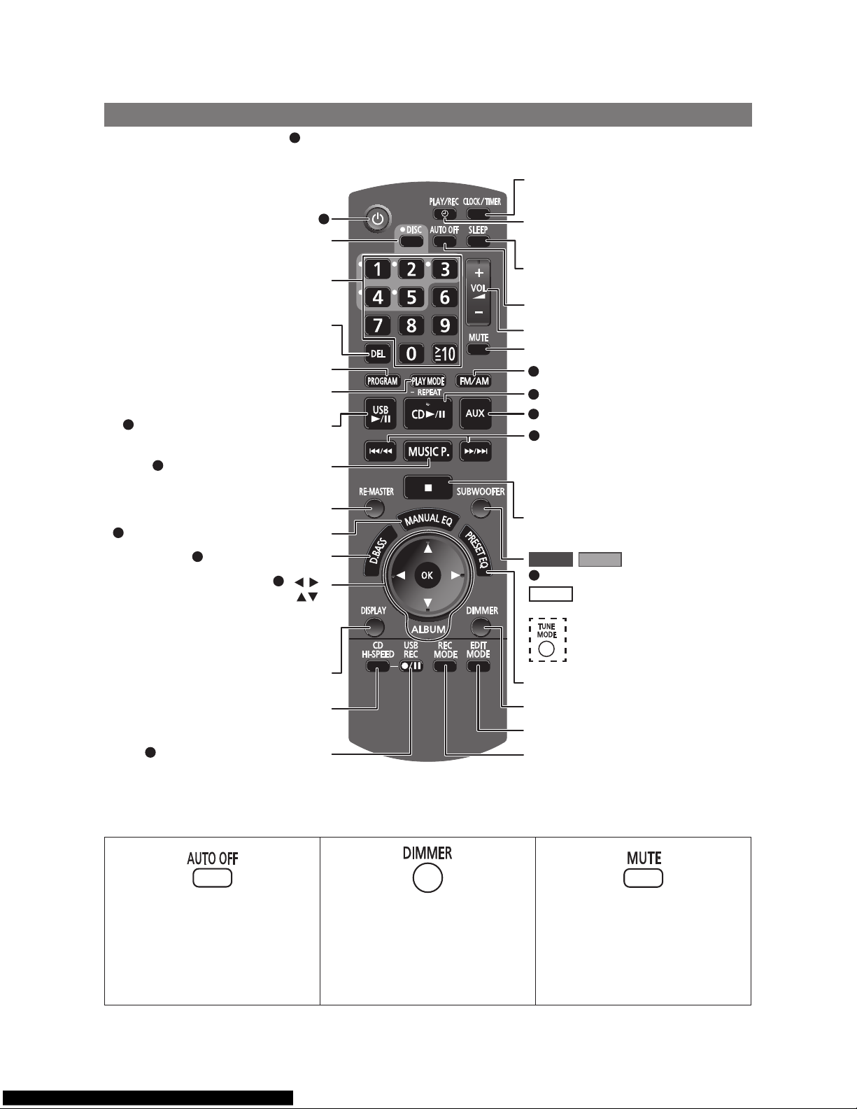
5.2. Remote Control Key Button Operation
Control remotoControl remoto
Los botones con etiquetas como el funcionan exactamente del mismo modo que los botones del aparato principal
página 7).
(
1
Confi guración de reloj o temporizador (15)
Selección del d
Selección numérica (9, 12, 17)
Fun
Fun
ción del programa (10, 12)
Función del modo de reproducción (9, 11, 13),
Reproducción o pausa del USB (12)
2
Selección puerto de música (17)
3
Selección de ecualiza
4
Selección de álbum (9, 12) [ ],
onfirmar selección (10, 12, 14, 17) [OK]
C
Fun
Selección RE-MASTER (16)
Selección D.BASS (16)
5
iscos (9)
ción borrar (10)
ción repetir (10)
dor manual (16)
10
[ ],
1
Configuración de temporizador de
reproducción o temporizador de grabación
(15)
Configuración de temporizador de apagado
automático (15)
Función de a
rol de volumen (12, 15)
Cont
Función de desactiva
Selección sintoniza
7
Reproducción o pausa del d
8
9
Selección AUX (17)
10
Saltar o buscar pista, verificar contenido
de programa, selección de canales
predeterminados, función de sintonización,
configuración de hora, configuración de
ecualizador manual (9 a 12, 15, 16)
Detener reproducción o borrar programa
(9, 10, 12)
AK780 AK785
Selección de nivel de subwoofer (16)
11
AK580
Selección del modo de sintonización (11)
pagado automático
ción de sonido
dor (FM/AM) (11)
isco (9)
Función visualiza
Función de graba
Graba
6
Esta función de apagado automático le
permite que el apa
o USB , se apague sólo después de 10
minutos sin utilizarse.
se el botón para activar la función.
• Pul
• P
ulse el botón nuevamente para cancelar.
• El ajuste se mantiene aunque el apa
esté apa
ción o pausa del USB (13)
rato en modo disco
gado.
ción (10, 12)
ción de CD a alta
veloc
idad (13)
Para reducir la iluminación del la pantalla.
• Pulse el botón para activar la función.
• Pulse el botón nuevamente para cancelar.
rato
Selección del ecualizador preajustado (16)
nción atenuador
Fu
Función modo editar (14)
Selección de modo de graba
Para sil
enciar el sonido.
se el botón para activar la función.
• Pul
• Pul
se el botón nuevamente o ajuste el
volumen pa
ra cancelar.
ción (14)

16
5.3. Disc Information
17
6 Self-Diagnosis and Special Mode Setting
This unit is equipped with features od self-diagnosis & special mode setting for checking the function & reliability.
Special Note: Checking of the reliability (ageing) & changer operation must be carry out to ensure good working condition in unit.
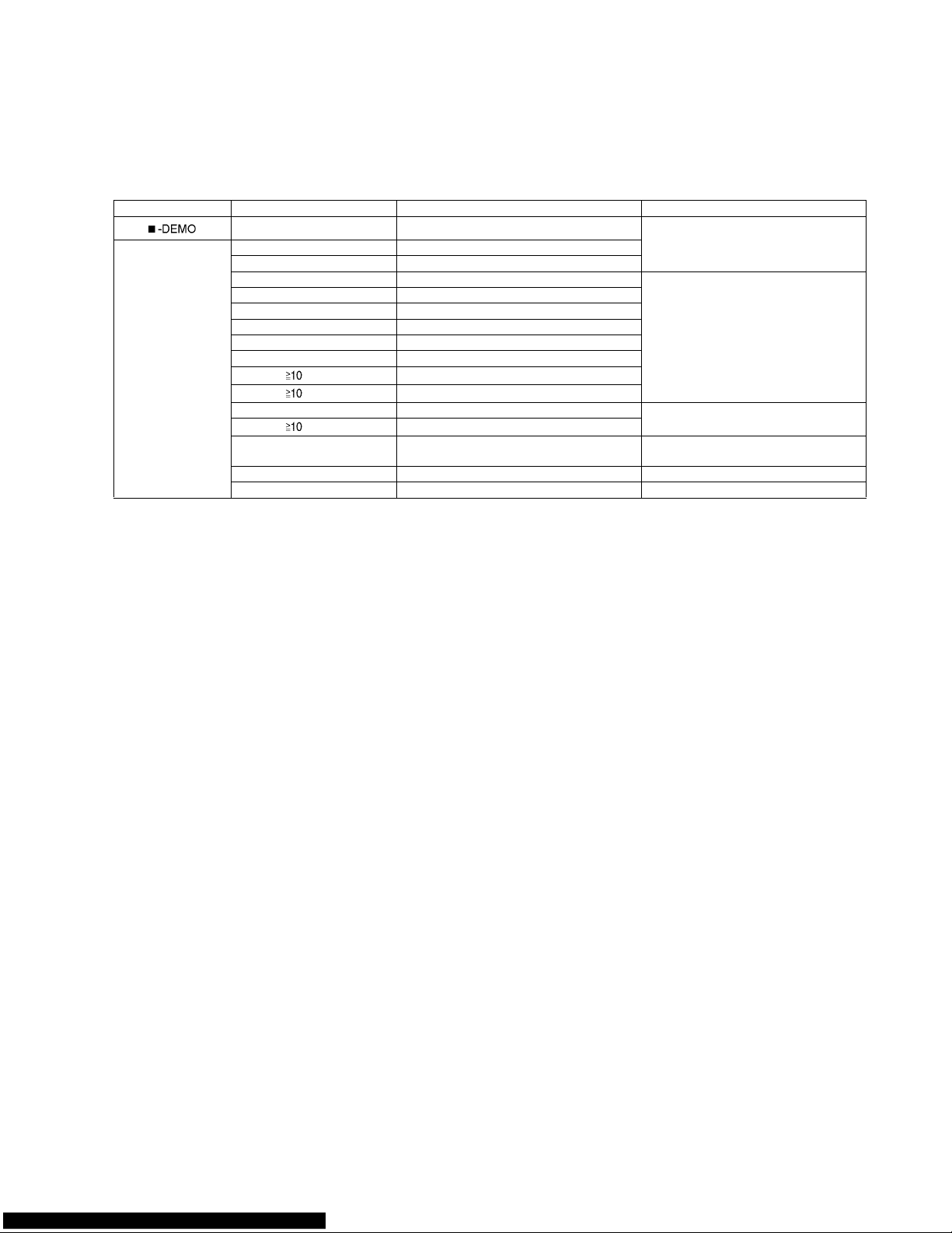
6.1. Doctor Mode Summary Table
Main unit buttons Remote control unit buttons Application Note
[]
[4], [7] Doctor Mode (Refer to the section “6.2.1 Doctor Mode
Table 1” for more information.)
Doctor Mode [DISPLAY] Cold Start
[2] Micro-P Version Display
[7] Volume 50 Setting Check (Refer to the section “6.2.2 Doctor Mode
Table 2” for more information.)
[8] Volume 35 Setting Check
[9] Volume 0 Setting Check
[PLAYMODE/-REPEAT] Volume 30 Setting Check
[1] FL Display Check
[DEL] CD Open Test
[ ], [1], [1]
CR14 Reliability Test 1 (no retry)
[ ], [1], [2]
CR14 Reliability Test 2 (with retry)
[DISC] CR14 Changer Mechanism Check (Refer to the section “6.2.3 Doctor Mode
Table 3” for more information.)
[ ], [9], [4]
CR14 Error Late Display
[4] CD to USB Recording & Playing Inspection (Refer to the section “6.2.4 Doctor Mode
Table 4” for more information.)
[FM/AM] Tuner Inspection
[OK] Exit Inspection Mode
18
6.2. Doctor Mode Table
Below is the various special modes for checking:-
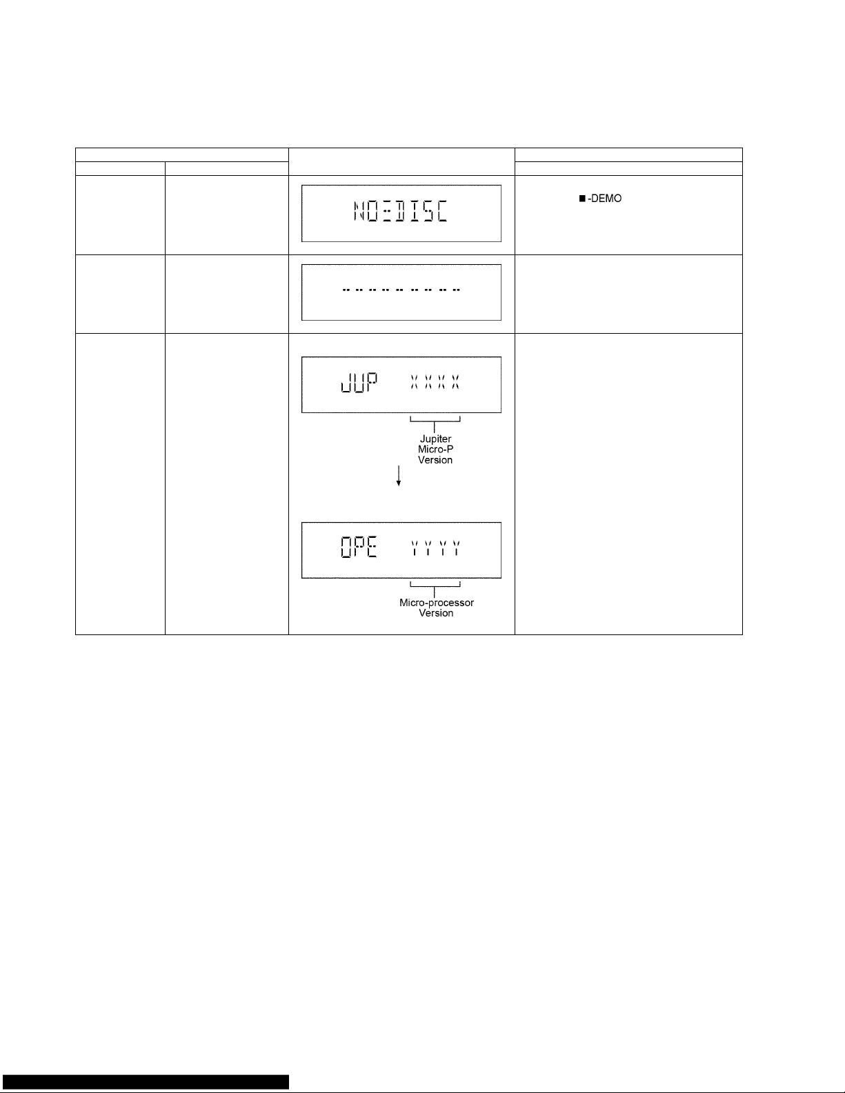
6.2.1. Doctor Mode Table 1
Item FL Display Key Operation
Mode Name Description Front Key
Doctor Mode To enter into Doctor
Mode.
In CD Mode:
1. Press [ ] button on main unit follow by [4] and [7] on remote control.
To exit Doctor Mode, press [OK] button on
remote control.
Cold Start To activate cold start upon
next power up when
reset is execute the next
time.
In Doctor Mode:
1. Press [DISPLAY] button on remote control.
Micro-P Version
Display
To check the firmware
version for Jupiter &
Microprocessor IC.
Display 1
Display 2
In Doctor Mode:
1. Press [2] button on remote control.
19
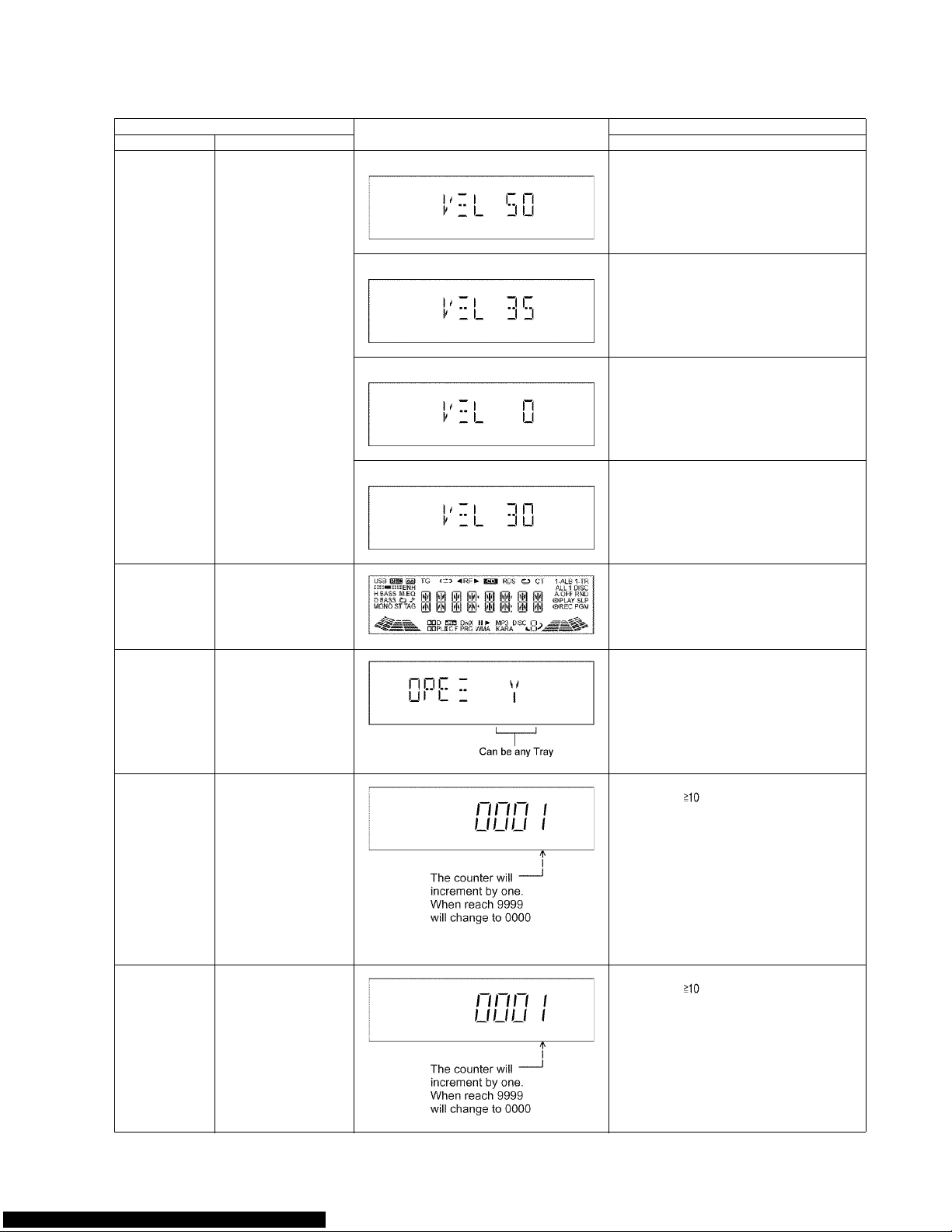
6.2.2. Doctor Mode Table 2
Item FL Display Key Operation
Mode Name Description Front Key
Volume Setting
Check
To check for the volume
setting of the main unit.
The volume will be automatically set to its respective level (in dB). During
this mode, treble/bass/EQ
will be set to ‘0’dB & OFF.
Display 1 In Doctor Mode:
1. Press [7] button on remote control.
To exit Doctor Mode, press [OK] button on main
unit or remote control.
Display 1 In Doctor Mode:
2. Press [8] button on remote control.
To exit Doctor Mode, press [OK] button on main
unit or remote control.
Display 1 In Doctor Mode:
3. Press [9] button on remote control.
To exit Doctor Mode, press [OK] button on main
unit or remote control.
Display 1 In Doctor Mode:
4. Press [PLAY MODE/-REPEAT] button on
remote control.
To exit Doctor Mode, press [OK] button on main
unit or remote control.
FL Display Check To check the FL
segments display (All
segments will light up)
In Doctor Mode:
1. Press [1] button on remote control.
CD OPEN Test To check the CD OPEN
operation.
In Doctor Mode:
1. Press [DEL] button on remote control.
2. Press [OPEN/CLOSE] button on main unit
to close the disc tray.
CR14 Reliability
Test1 (no retry)
Note:
1. If the mechanism
error occurs, it
should stop the
test.
(no retry, no recovery process).
2. The test mode is
cleared by power
OFF.
3. Reading and playback should not be
done.
In Doctor Mode:
1. Press [ ], [1], [1] button on remote control.
CR14 Reliability
Test2 (with retry)
Note:
1. Even if the mechanism error occurs, it
should retry as normal operation.
2. The test mode is
cleared by power
OFF.
3. Reading and playback should not be
done.
In Doctor Mode:
1. Press [ ], [1], [2] button on remote control.
20
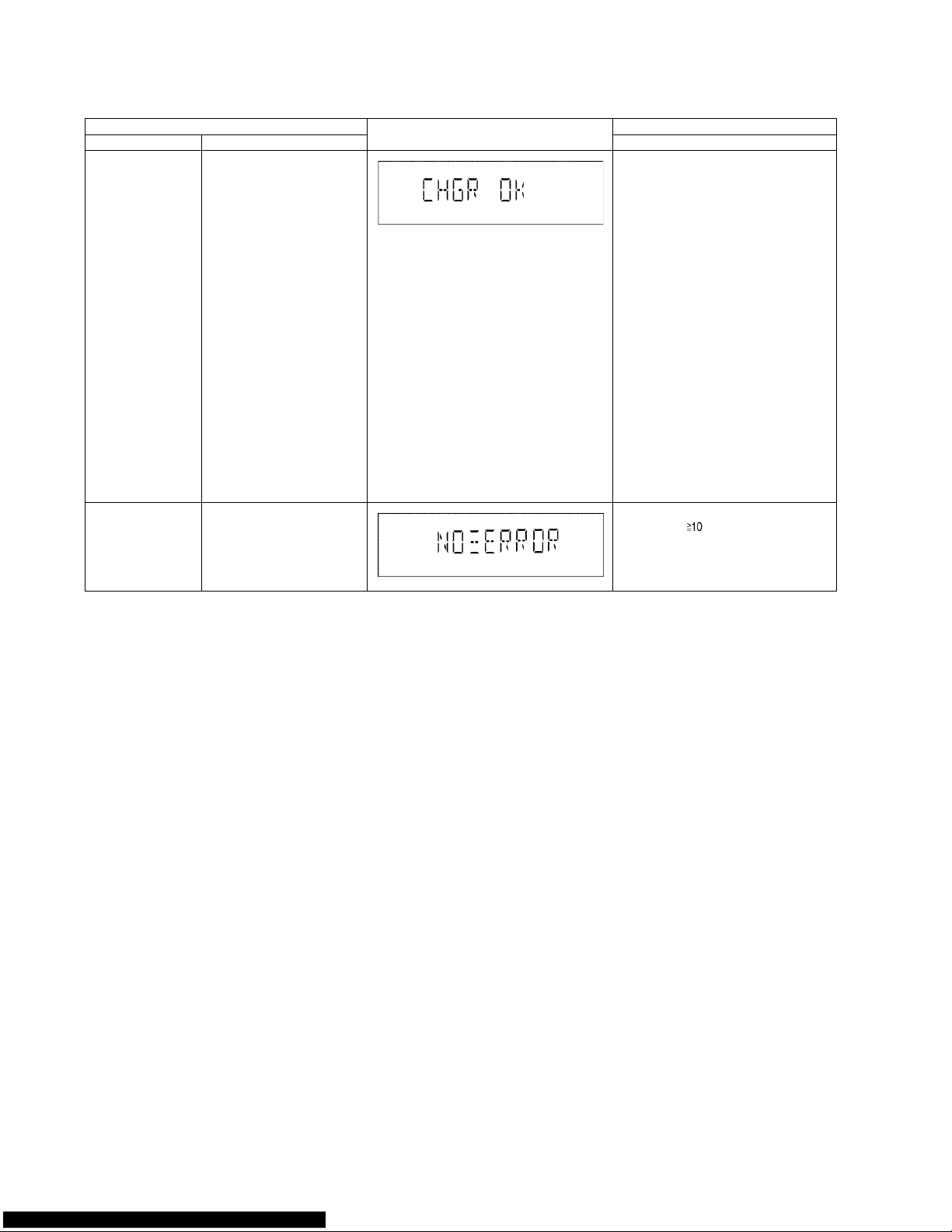
6.2.3. Doctor Mode Table 3
Item FL Display Key Operation
Mode Name Description Front Key
CR14 Inspection Below is the process:
1. Load TRAY 1 (Move to
PLAY position)
2. After that, TRAY 2 is
open (TRAY 1 still in
LOAD condition) and
close.
3. Next TRAY 3 is open
(TRAY 1 still in LOAD
condition) and close.
4. Then TRAY 4 is open
(TRAY 1 still in LOAD
condition) and close.
5. Finally TRAY 5 is open
(TRAY 1 still in LOAD
condition) and close.
6. Tray 1 is unloaded.
(Move to the STOCK
position)
7. Tray 1 is loaded. (Move
to the PLAY position)
When step 1 to 7 operates normally without any error, FL will
display [CHGR_OK_]
In Doctor Mode:
1. Press [DISC] button on remote control.
CR14 Error Code
Display
To display errors codes for
CR14 changer mechanism.
Refer to section 6.4.1 (CD
Mechanism (CR14) Error code
table).
In Doctor Mode:
1. Press [ ], [9], [4] button on
remote control.

21
6.2.4. Doctor Mode Table 4
Item FL Display Key Operation
Mode Name Description Front Key
CD to USB Recording
& Playing Inspection
-Automatically change to CD
-Set it to VOL 0
-Preset EQ Set to FLAT
USB Formatted
When high-speed recording
When analog recording
- Switches to the USB selector
after an analog recording ends
(TRACK 1 of ALBUM1)
During playback this track
- Sets to VOL 50 (0dB) and
start playback
- It is enabled to accept the
SKIP key and the ALBUM key
Next, play the track analog
recorded. (TRACK1 of
ALBUM2)
During playback this track
- It is enabled to accept the
SKIP key and the ALBUM key
In Doctor Mode:
1. Press [4] button on remote control.

22
6.3. Service Mode Summary Table
Main unit buttons Remote control unit buttons Application Note
[]
[]
Service Mode (Refer to the section “6.4.1 Service Mode
Table 1” for more information.)
Service Mode [1] Error Code History
[2] Micro-P Version Display
[5] USB Error Code History
[6] CD Self Adjustment Result (Refer to the section “6.4.2 Service Mode
Table 2” for more information.)
[3] Cold Start
23
6.4. Service Mode Table
6.4.1. Service Mode Table 1
Below is the various special modes for checking:-
Item FL Display Key Operation
Mode Name Description Front Key
Service Mode To enter into Service
Mode.
In CD Mode:
Press and hold [ ] button on main unit
for 2 seconds follow by [ ] on remote control
for 2 seconds.
To exit, press [ON/OFF ] button on main unit
or remote control.
Error Code History Checking the records for
Error Code.
In Service Mode:
1. Press [1] button on remote control.
To clear history, press & hold [0] for 5 seconds or
more.
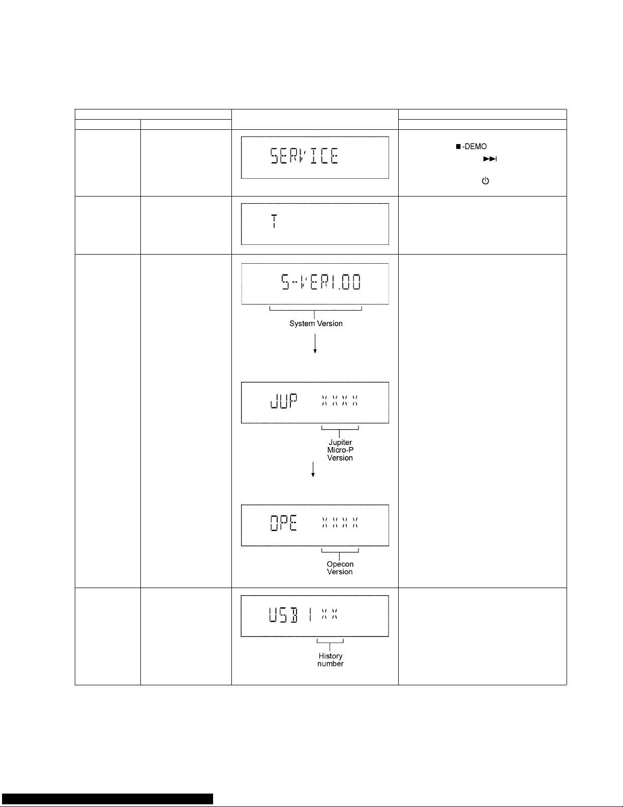
Micro-P Version
Display
To Check for following:
1) System Version.
2) Jupiter Micro-processor version.
3) Micro-processor Version
In Service Mode:
1. Press [2] button on remote control.
(Display 1)
(Display 2)
USB Error Code
History
To check for USB error
codes.
In Service Mode:
1. Press [5] button on remote control.
To clear history, press & hold [0] for 5 seconds or
more.

24
6.4.2. Service Mode Table 2
Item FL Display Key Operation
Mode Name Description Front Key
CD Self Adjustment Result
To check for CD operation
(self-adjusment).
In Service Mode:
1. Press [6] button on remote control.
Cold Start To reset to default setting. In Service Mode:
1. Press [3] button on remote control.

25
6.5. Reliability Test Mode (CD Mechanism Unit CR14C)
Below is the progress flow chart of ageing for the Mechanism unit (CR14C).
㪈㩷㫇㫃㪸㫐
㸣
㫌㫅㫃㫆㪸㪻
㸣㸣㸣㸣㸣
㪈㩷㫆㫇㪼㫅 㪈㩷㫆㫇㪼㫅 㪈㩷㫆㫇㪼㫅 㪈㩷㫇㫃㪸㫐 㪈㩷㫆㫇㪼㫅
㸣㸣㸣㸣㸣
㪌㪇㪇㫄㫊㩷㪮㪸㫀㫋 㪌㪇㪇㫄㫊㩷㪮㪸㫀㫋 㪌㪇㪇㫄㫊㩷㪮㪸㫀㫋 㪚㫆㫌㫅㫋㩷㫌㫇 㪌㪇㪇㫄㫊㩷㪮㪸㫀㫋
㸣㸣㸣㸣㸣
㪺㫃㫆㫊㪼 㪺㫃㫆㫊㪼 㪺㫃㫆㫊㪼 㪌㪇㪇㫄㫊㩷㪮㪸㫀㫋 㪺㫃㫆㫊㪼
㸣㸣㸣㸣㸣
㪈㩷㫇㫃㪸㫐 㪈㩷㫇㫃㪸㫐 㪈㩷㫇㫃㪸㫐 㪈㩷㫇㫃㪸㫐㩷㫆㫇㪼㫅 㪈㩷㫇㫃㪸㫐
㸣㸣㸣㸣㸣
㪚㫆㫌㫅㫋㩷㫌㫇 㪚㫆㫌㫅㫋㩷㫌㫇 㪚㫆㫌㫅㫋㩷㫌㫇 㪌㪇㪇㫄㫊㩷㪮㪸㫀㫋 㪚㫆㫌㫅㫋㩷㫌㫇
㸣㸣㸣㸣㸣
㪌㪇㪇㫄㫊㩷㪮㪸㫀㫋 㪌㪇㪇㫄㫊㩷㪮㪸㫀㫋 㪌㪇㪇㫄㫊㩷㪮㪸㫀㫋 㪺㫃㫆㫊㪼 㪌㪇㪇㫄㫊㩷㪮㪸㫀㫋
㸣㸣㸣㸣㸣
㫌㫅㫃㫆㪸㪻 㫌㫅㫃㫆㪸㪻 㫌㫅㫃㫆㪸㪻 㫌㫅㫃㫆㪸㪻 㫌㫅㫃㫆㪸㪻
㸣㸣㸣㸣㸣
㪌㩷㫇㫃㪸㫐 㪌㩷㫇㫃㪸㫐 㪌㩷㫇㫃㪸㫐 㪌㩷㫇㫃㪸㫐 㪌㩷㫇㫃㪸㫐
㸣㸣㸣㸣㸣
㪚㫆㫌㫅㫋㩷㫌㫇 㪚㫆㫌㫅㫋㩷㫌㫇 㪚㫆㫌㫅㫋㩷㫌㫇 㪚㫆㫌㫅㫋㩷㫌㫇 㪚㫆㫌㫅㫋㩷㫌㫇
㸣㸣㸣㸣㸣
㪌㪇㪇㫄㫊㩷㪮㪸㫀㫋 㪌㪇㪇㫄㫊㩷㪮㪸㫀㫋 㪌㪇㪇㫄㫊㩷㪮㪸㫀㫋 㪌㪇㪇㫄㫊㩷㪮㪸㫀㫋 㪌㪇㪇㫄㫊㩷㪮㪸㫀㫋
㸣㸣㸣㸣㸣
㫌㫅㫃㫆㪸㪻 㫌㫅㫃㫆㪸㪻 㫌㫅㫃㫆㪸㪻 㫌㫅㫃㫆㪸㪻 㪌㩷㫇㫃㪸㫐㩷㫆㫇㪼㫅
㸣㸣㸣㸣㸣
㪌㩷㫆㫇㪼㫅 㪌㩷㫆㫇㪼㫅 㪌㩷㫆㫇㪼㫅 㪌㩷㫆㫇㪼㫅 㪌㪇㪇㫄㫊㩷㪮㪸㫀㫋
㸣㸣㸣㸣㸣
㪌㪇㪇㫄㫊㩷㪮㪸㫀㫋 㪌㪇㪇㫄㫊㩷㪮㪸㫀㫋 㪌㪇㪇㫄㫊㩷㪮㪸㫀㫋 㪌㪇㪇㫄㫊㩷㪮㪸㫀㫋 㪺㫃㫆㫊㪼
㸣㸣㸣㸣㸣
㪺㫃㫆㫊㪼 㪺㫃㫆㫊㪼 㪺㫃㫆㫊㪼 㪺㫃㫆㫊㪼 㫌㫅㫃㫆㪸㪻
㸣㸣㸣㸣㸣
㪊㩷㫇㫃㪸㫐 㪊㩷㫆㫇㪼㫅 㪊㩷㫆㫇㪼㫅 㪊㩷㫆㫇㪼㫅 㪊㩷㫆㫇㪼㫅
㸣㸣㸣㸣㸣
㪚㫆㫌㫅㫋㩷㫌㫇 㪌㪇㪇㫄㫊㩷㪮㪸㫀㫋 㪌㪇㪇㫄㫊㩷㪮㪸㫀㫋 㪌㪇㪇㫄㫊㩷㪮㪸㫀㫋 㪌㪇㪇㫄㫊㩷㪮㪸㫀㫋
㸣㸣㸣㸣㸣
㪌㪇㪇㫄㫊㩷㪮㪸㫀㫋 㪺㫃㫆㫊㪼 㪺㫃㫆㫊㪼 㪺㫃㫆㫊㪼 㪺㫃㫆㫊㪼
㸣㸣㸣㸣㸣
㪊㩷㫇㫃㪸㫐㩷㫆㫇㪼㫅 㪊㩷㫇㫃㪸㫐 㪊㩷㫇㫃㪸㫐 㪊㩷㫇㫃㪸㫐 㪊㩷㫇㫃㪸㫐
㸣㸣㸣㸣㸣
㪌㪇㪇㫄㫊㩷㪮㪸㫀㫋 㪚㫆㫌㫅㫋㩷㫌㫇 㪚㫆㫌㫅㫋㩷㫌㫇 㪚㫆㫌㫅㫋㩷㫌㫇 㪚㫆㫌㫅㫋㩷㫌㫇
㸣㸣㸣㸣㸣
㪺㫃㫆㫊㪼 㪌㪇㪇㫄㫊㩷㪮㪸㫀㫋 㪌㪇㪇㫄㫊㩷㪮㪸㫀㫋 㪌㪇㪇㫄㫊㩷㪮㪸㫀㫋 㪌㪇㪇㫄㫊㩷㪮㪸㫀㫋
㸣㸣㸣㸣㸣
㫌㫅㫃㫆㪸㪻 㫌㫅㫃㫆㪸㪻 㫌㫅㫃㫆㪸㪻 㫌㫅㫃㫆㪸㪻 㫌㫅㫃㫆㪸㪻
㸣㸣㸣㸣㸣
㪋㩷㫆㫇㪼㫅 㪋㩷㫇㫃㪸㫐 㪋㩷㫆㫇㪼㫅 㪋㩷㫆㫇㪼㫅 㪋㩷㫆㫇㪼㫅
㸣㸣㸣㸣㸣
㪌㪇㪇㫄㫊㩷㪮㪸㫀㫋 㪚㫆㫌㫅㫋㩷㫌㫇 㪌㪇㪇㫄㫊㩷㪮㪸㫀㫋 㪌㪇㪇㫄㫊㩷㪮㪸㫀㫋 㪌㪇㪇㫄㫊㩷㪮㪸㫀㫋
㸣㸣㸣㸣㸣
㪺㫃㫆㫊㪼 㪌㪇㪇㫄㫊㩷㪮㪸㫀㫋 㪺㫃㫆㫊㪼 㪺㫃㫆㫊㪼 㪺㫃㫆㫊㪼
㸣㸣㸣㸣㸣
㪋㩷㫇㫃㪸㫐 㪋㩷㫇㫃㪸㫐㩷㫆㫇㪼㫅 㪋㩷㫇㫃㪸㫐 㪋㩷㫇㫃㪸㫐 㪋㩷㫇㫃㪸㫐
㸣㸣㸣㸣㸣
㪚㫆㫌㫅㫋㩷㫌㫇 㪌㪇㪇㫄㫊㩷㪮㪸㫀㫋 㪚㫆㫌㫅㫋㩷㫌㫇 㪚㫆㫌㫅㫋㩷㫌㫇 㪚㫆㫌㫅㫋㩷㫌㫇
㸣㸣㸣㸣㸣
㪌㪇㪇㫄㫊㩷㪮㪸㫀㫋 㪺㫃㫆㫊㪼 㪌㪇㪇㫄㫊㩷㪮㪸㫀㫋 㪌㪇㪇㫄㫊㩷㪮㪸㫀㫋 㪌㪇㪇㫄㫊㩷㪮㪸㫀㫋
㸣㸣㸣㸣㸣
㫌㫅㫃㫆㪸㪻 㫌㫅㫃㫆㪸㪻 㫌㫅㫃㫆㪸㪻 㫌㫅㫃㫆㪸㪻 㫌㫅㫃㫆㪸㪻
㸣㸣㸣㸣㸣
㪉㩷㫇㫃㪸㫐 㪉㩷㫇㫃㪸㫐 㪉㩷㫇㫃㪸㫐 㪉㩷㫇㫃㪸㫐 㪉㩷㫇㫃㪸㫐
㸣㸣㸣㸣㸣
㪚㫆㫌㫅㫋㩷㫌㫇 㪚㫆㫌㫅㫋㩷㫌㫇 㪚㫆㫌㫅㫋㩷㫌㫇 㪚㫆㫌㫅㫋㩷㫌㫇 㪚㫆㫌㫅㫋㩷㫌㫇
㸣㸣㸣㸣㸣
㪌㪇㪇㫄㫊㩷㪮㪸㫀㫋 㪌㪇㪇㫄㫊㩷㪮㪸㫀㫋 㪌㪇㪇㫄㫊㩷㪮㪸㫀㫋 㪌㪇㪇㫄㫊㩷㪮㪸㫀㫋 㪌㪇㪇㫄㫊㩷㪮㪸㫀㫋
㸣㸣㸣㸣㸣
㫌㫅㫃㫆㪸㪻 㫌㫅㫃㫆㪸㪻 㪉㩷㫇㫃㪸㫐㩷㫆㫇㪼㫅 㫌㫅㫃㫆㪸㪻 㫌㫅㫃㫆㪸㪻
㸣㸣㸣㸣㸣
㪉㩷㫆㫇㪼㫅 㪉㩷㫆㫇㪼㫅 㪌㪇㪇㫄㫊㩷㪮㪸㫀㫋 㪉㩷㫆㫇㪼㫅 㪉㩷㫆㫇㪼㫅
㸣㸣㸣㸣㸣
㪌㪇㪇㫄㫊㩷㪮㪸㫀㫋 㪌㪇㪇㫄㫊㩷㪮㪸㫀㫋 㪺㫃㫆㫊㪼 㪌㪇㪇㫄㫊㩷㪮㪸㫀㫋 㪌㪇㪇㫄㫊㩷㪮㪸㫀㫋
㸣㸣㸣㸣㸣
㪺㫃㫆㫊㪼 㪺㫃㫆㫊㪼 㫌㫅㫃㫆㪸㪻 㪺㫃㫆㫊㪼 㪺㫃㫆㫊㪼
㸣㸣㸣㸣㸣

26
6.6. Error Code Table
Self-Diagnosis Function (refer Section “6.4.1” Service Mode Table 1”) provides information on any problems occurring for the unit
and its respective components by displaying the error codes. These error code such as U**, H** and F** are stored in memory and
held unless it is cleared.
The error code is automatically display after entering into self-diagnostic mode.
6.6.1. CD Mechanism Unit (CR14C) Error Code Table

27
6.6.2. Error Code Table (For Power Supply)

28
7 Troubleshooting Guide
7.1. Jupiter USB

29
7.2. Troubleshooting Guide
30
 Loading...