

Panasonic S-200PE2E5, S-250PE2E5, U-250PE2E8A, S-100PU2E5A, S-125PU2E5A Service Manual
...
TECHNICAL DATA& SERVICE MANUAL
AMP Air Conditioning
www.ampair.co.uk | sales@ampair.co.uk
Order No. SBPAC1607004CE
Outdoor UnitIndoor Unit
High Static Pressure
Ducted Type
Type E2
S-200PE2E5, S-250PE2E5
Type U2
S-100PU2E5A, S-125PU2E5A
4-Way Cassette Type
U-200PE2E8A, U-250PE2E8A
85464849352001
REFERENCE NO
.
SM830252-01

IMPORTANT!
WARNING
WARNING
…In a Snowy Area (for Heat Pump-
type Systems)
Install the outdoor unit on a raised
platform that is higher than drifting snow.
Provide snow vents.
…At least 2.5 m
Indoor unit of this air conditioner shall be
installed in a height of at least 2.5 m.
…In laundry rooms
Do not install in laundry rooms. Indoor
unit is not drip proof.
When Connecting Refrigerant Tubing
WARNING
WARNING
•
When performing piping work do not
mix air except for specified refrigerant
(R410A) in refrigeration cycle. It
causes capacity down, and risk of
explosion and injury due to high
tension inside the refrigerant cycle.
• Refrigerantgasleakagemaycausefire.
• Donotaddorreplacerefrigerant
other than specified type. It may
cause product damage, burst and
injury, etc.
• Ventilatetheroomwell,intheevent
that is refrigerant gas leaks during
the installation. Be careful not to allow
contact of the refrigerant gas with a
flame as this will cause the generation
of poisonous gas.
• Keepalltubingrunsasshortas
possible.
• Usetheflaremethodforconnecting
tubing.
• Applyrefrigerantlubricanttothe
matching surfaces of the flare and union
tubes before connecting them, then
tighten the nut with a torque wrench for
a leak-free connection.
• Checkcarefullyforleaksbeforestarting
the test run.
• Donotleakrefrigerantwhilepiping
work for an installation or re-installation,
and while repairing refrigeration parts.
Handle liquid refrigerant carefully as it
may cause frostbite.
When Servicing
• TurnthepowerOFFatthemain
power box (mains) before opening
the unit to check or repair electrical
parts and wiring.
• Keepyourfingersandclothingaway
from any moving parts.
• Cleanupthesiteafteryoufinish,
remembering to check that no metal
scraps or bits of wiring have been left
inside the unit being serviced.
WARNING
WARNING
• Thisproductmustnotbe
modified or disassembled under
any circumstances. Modified or
disassembled unit may cause fire,
electric shock or injury.
• Donotcleaninsidetheindoorand
outdoor units by users. Engage
authorized dealer or specialist for
cleaning.
• Incaseofmalfunctionofthis
appliance, do not repair by yourself.
Contact the sales dealer or service
dealer for repair.
WARNING
CAUTION
• Donottouchtheairinletorthe
sharp aluminum fins of the
outdoor unit. You may get injured.
• Ventilateanyenclosedareaswhen
installing or testing the refrigeration
system. Escaped refrigerant gas,
on contact with fire or heat, can
produce dangerously toxic gas.
• Confirmafterinstallationthatno
refrigerant gas is leaking. If the gas
comes in contact with a burning
stove, gas water heater, electric
room heater or other heat source,
it can cause the generation of
poisonous gas.
Others
WARNING
CAUTION
• Donotsitorstepontheunit,you
may fall down accidentally.
• Donottouchtheairinletorthe
sharp aluminum fins of the
outdoor unit. You may get injured.
• Donotstickanyobjectintothe
FAN CASE.
You may be injured and the unit
may be damaged.
AMP Air Conditioning
www.ampair.co.uk | sales@ampair.co.uk
Please Read Before Starting
This air conditioner must be installed by the sales dealer
or installer.
This information is provided for use only by authorized
persons.
For safe installation and trouble-free operation, you must:
●
Carefully read this instruction booklet before beginning.
●
Follow each installation or repair step exactly as shown.
●
This air conditioner shall be installed in accordance with
National Wiring Regulations.
●
Pay close attention to all warning and caution notices
given in this manual.
WARNING
CAUTION
If Necessary, Get Help
These instructions are all you need for most installation
sites and maintenance conditions. If you require help for a
special problem, contact our sales/service outlet or your
certified dealer for additional instructions.
In Case of Improper Installation
The manufacturer shall in no way be responsible for
improper installation or maintenance service, including
failure to follow the instructions in this document.
This symbol refers to a hazard or unsafe
practice which can result in severe
personal injury or death.
This symbol refers to a hazard or unsafe
practice which can result in personal injury
or product or property damage.
SPECIAL PRECAUTIONS
WARNING
When Wiring
•Donotsupplypowertotheunituntil
all wiring and tubing are completed or
reconnected and checked.
•Highlydangerouselectricalvoltagesare
used in this system.
Carefully refer to the wiring diagram and
these instructions when wiring. Improper
ELECTRICAL SHOCK CAN
CAUSE SEVERE PERSONAL
INJURY OR DEATH. ONLY A
QUALIFIED, EXPERIENCED
ELECTRICIAN SHOULD
ATTEMPT TO WIRE THIS
SYSTEM.
connections and inadequate grounding
can cause accidental injury or death.
•Connectallwiringtightly.Loosewiring
may cause overheating at connection
points and a possible fire hazard.
• Provide a power outlet to be used
exclusively for each unit.
• Provide a power outlet exclusively for
each unit, and full disconnection means
having a contact separation in all poles
must be incorporated in the fixed wiring
in accordance with the wiring rules.
• To prevent possible hazards from
insulation failure, the unit must be
grounded.
• This equipment is strongly recommended
When Transporting
Be careful when picking up and moving
the indoor and outdoor units. Get a partner
to help, and bend your knees when lifting
to reduce strain on your back. Sharp
edges or thin aluminum fins on the air
conditioner can cut your fingers.
When Installing…
to be installed with Earth Leakage
Circuit Breaker (ELCB) or Residual
Current Device (RCD). Otherwise, it may
cause electrical shock and fire in case
of equipment breakdown or insulation
breakdown.
Select an installation location which is
rigid and strong enough to support or hold
the unit, and select a location for easy
maintenance.
…In a Room
Properly insulate any tubing run inside a
room to prevent “sweating” that can cause
dripping and water damage to walls and
floors.
CAUTION
Keep the fire alarm and
the air outlet at least
1.5 m away from the unit.
…In Moist or Uneven Locations
Use a raised concrete pad or concrete
blocks to provide a solid, level foundation
for the outdoor unit. This prevents water
damage and abnormal vibration.
…In an Area with High Winds
Securely anchor the outdoor unit down
with bolts and a metal frame. Provide a
suitable air baffle.
i
…In a Snowy Area (for Heat Pump-
WARNING
WARNING
WARNING
WARNING
AMP Air Conditioning
www.ampair.co.uk | sales@ampair.co.uk
type Systems)
Install the outdoor unit on a raised
platform that is higher than drifting snow.
Provide snow vents.
…At least 2.5 m
Indoor unit of this air conditioner shall be
installed in a height of at least 2.5 m.
…In laundry rooms
Do not install in laundry rooms. Indoor
unit is not drip proof.
When Connecting Refrigerant Tubing
WARNING
•
When performing piping work do not
mix air except for specified refrigerant
(R410A) in refrigeration cycle. It
causes capacity down, and risk of
explosion and injury due to high
tension inside the refrigerant cycle.
• Refrigerantgasleakagemaycausefire.
• Donotaddorreplacerefrigerant
other than specified type. It may
cause product damage, burst and
injury, etc.
• Ventilatetheroomwell,intheevent
that is refrigerant gas leaks during
the installation. Be careful not to allow
contact of the refrigerant gas with a
flame as this will cause the generation
of poisonous gas.
• Keepalltubingrunsasshortas
possible.
• Usetheflaremethodforconnecting
tubing.
• Applyrefrigerantlubricanttothe
matching surfaces of the flare and union
tubes before connecting them, then
tighten the nut with a torque wrench for
a leak-free connection.
• Checkcarefullyforleaksbeforestarting
the test run.
• Donotleakrefrigerantwhilepiping
work for an installation or re-installation,
and while repairing refrigeration parts.
Handle liquid refrigerant carefully as it
may cause frostbite.
When Servicing
• TurnthepowerOFFatthemain
power box (mains) before opening
the unit to check or repair electrical
parts and wiring.
• Keepyourfingersandclothingaway
from any moving parts.
• Cleanupthesiteafteryoufinish,
remembering to check that no metal
scraps or bits of wiring have been left
inside the unit being serviced.
WARNING
• Thisproductmustnotbe
modified or disassembled under
any circumstances. Modified or
disassembled unit may cause fire,
electric shock or injury.
• Donotcleaninsidetheindoorand
outdoor units by users. Engage
authorized dealer or specialist for
cleaning.
• Incaseofmalfunctionofthis
appliance, do not repair by yourself.
Contact the sales dealer or service
dealer for repair.
CAUTION
• Donottouchtheairinletorthe
sharp aluminum fins of the
outdoor unit. You may get injured.
• Ventilateanyenclosedareaswhen
installing or testing the refrigeration
system. Escaped refrigerant gas,
on contact with fire or heat, can
produce dangerously toxic gas.
• Confirmafterinstallationthatno
refrigerant gas is leaking. If the gas
comes in contact with a burning
stove, gas water heater, electric
room heater or other heat source,
it can cause the generation of
poisonous gas.
Others
CAUTION
• Donotsitorstepontheunit,you
may fall down accidentally.
• Donottouchtheairinletorthe
sharp aluminum fins of the
outdoor unit. You may get injured.
• Donotstickanyobjectintothe
FAN CASE.
You may be injured and the unit
may be damaged.
ii
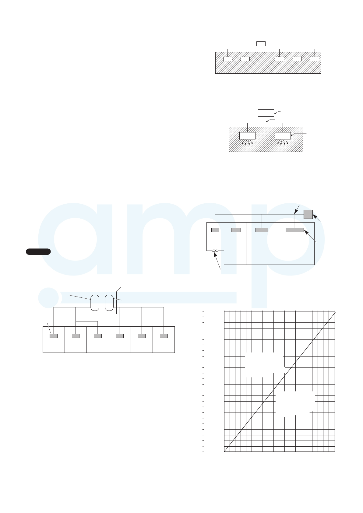
Check of Density Limit
The room in which the air conditioner is to be installed
—— CONTENTS ——
Section 1. SPECIFICATIONS .................................................................................................
1-1. Unit Specifications ...............................................................................................................
1-2. Major Component Specifications .......................................................................................
1-3. Other Component Specifications .....................................................................................
1-4. Dimensional Data ...............................................................................................................
1-5. Refrigerant Flow Diagram .................................................................................................
1-6. Operating Range ................................................................................................................
1-1
2-1
3-1
1-12
1-14
1-18
1-20
1-21
1-23
1-28
1-34
1-95
1-98
1-98
1-99
1-100
1-100
1-101
3-2
3-3
1-6
1-2
1-7. Capacity Correction Graph According to Temperature Condition ................................
1-8. Noise Criterion Curves ......................................................................................................
1-25
1-26
1-9. Airflow Distance Chart .......................................................................................................
1-10. Fresh Air Intake ................................................................................................................
1-11. ELECTRICAL WIRING ......................................................................................................
1-12. Installation Instructions ...................................................................................................
Section 2. TEST RUN .............................................................................................................
Section 3. ELECTRICAL DATA ..............................................................................................
3-2. Indoor Units (Electric Wiring Diagram) ..............................................................................
3-1. Outdoor Units (Electric Wiring Diagram) ...........................................................................
4-1
4-2
4-8
Section 4. PROCESS AND FUNCTIONS................................................................................
4-2. Outdoor Unit Control PCB (ACXA73-04770, ACXA73-04750)...........................................
4-1. Control Functions ................................................................................................................
5-1
5-2
5-4
Section 5. TROUBLE DIAGNOSIS.........................................................................................
5-5
5-32
5-33
5-34
5-35
5-36
5-37
5-38
5-1. Contents of Remote Controller Switch Alarm Display .....................................................
5-2. Outdoor Unit Control Panel LED Display ...........................................................................
5-3. PAC System Alarm Codes ...................................................................................................
5-4. Inspection of Parts (Outdoor Unit) ...................................................................................
5-5. Symptom: Thermostat in OFF continues or cycles OFF & ON too frequently..............
5-6. Sensor Temperature Display Function
(Displayed regardless of operation and stop)
...
5-7. Table of Thermistor Characteristics .................................................................................
5-8. How to Remove the Compressor ......................................................................................
5-9. How to Remove the Electrical Component Box ..............................................................
5-10. Symptom: Thermostat in OFF continues cycles OFF & ON too frequently.................
6-1
6-2
6-2
Section 6. OUTDOOR UNIT MAINTENANCE REMOTE CONTROLLER..............................
6-3
6-8
6-10
6-11
6-1. Overview ...............................................................................................................................
6-2. Functions .............................................................................................................................
6-3. Normal Display Operations and Functions ........................................................................
6-4.
Monitoring Operations: Display of Indoor Unit and Outdoor Unit Sensor Temperatures
...
6-5. Monitoring the Outdoor Unit Alarm History: Display of Outdoor Unit Alarm History...
6-6. Settings Modes: Setting the Outdoor Unit EEPROM ......................................................
2-2
2-22-2. Caution...................................................................................................................................
2-22-3. Test Run Procedure..............................................................................................................
2-32-4. Items to Check Before the Test Run...................................................................................
2-32-5. Test Run Using the Remote Controller...............................................................................
2-42-6. Precautions............................................................................................................................
2-52-7. Table of Self-Diagnostic Functions and Corrections.........................................................
2-62-8. System Control......................................................................................................................
2-122-9. Caution for Pump Down.....................................................................................................
2-1. Preparing for Test Run ........................................................................................................
Indoor Units
4-124-3. Outdoor Unit HIC Board (ACXA73-04760)........................................................................
4-134-4. Indoor Unit Control PCB Switches and Functions..........................................................
1-13. HOW TO PROCESS TUBING ...........................................................................................
1-14. VACUUM PURGING .........................................................................................................
1-15. REGARDING REFRIGERANT FILLING ...........................................................................
1-16. PRECAUTIONS REGARDING TEST RUN .......................................................................
1-17. CHECKS AFTER INSTALLATION HAVE COMPLETED ................................................
1-18. REGARDING DELIVERY TO THE CUSTOMER .............................................................
1-19. Supplement .....................................................................................................................
AMP Air Conditioning
www.ampair.co.uk | sales@ampair.co.uk
requires a design that in the event of refrigerant gas
leaking out, its density will not exceed a set limit.
The refrigerant (R410A), which is used in the air conditioner,
is safe, without the toxicity or combustibility of ammonia, and
is not restricted by laws imposed to protect the ozone layer.
However, since it contains more than air, it poses the risk of
suffocation if its density should rise excessively. Suffocation
from leakage of refrigerant is almost non-existent. With the
recent increase in the number of high density buildings,
however, the installation of multi air conditioner systems is
on the increase because of the need for effective use of floor
space, individual control, and energy conservation by curtailing
heat and carrying power, etc.
Most importantly, the multi air conditioner system is able
to replenish a large amount of refrigerant compared to
conventional individual air conditioners. If a single unit of the
multi air conditioner system is to be installed in a small room,
select a suitable model and installation procedure so that if the
refrigerant accidentally leaks out, its density does not reach the
limit (and in the event of an emergency, measures can be made
before injury can occur).
In a room where the density may exceed the limit, create an
opening with adjacent rooms, or install mechanical ventilation
combined with a gas leak detection device. The density is as
given below.
Min. volume of the indoor unit installed room (m
The density limit of refrigerant which is used in multi air
conditioners is 0.3 kg/m
NOTE
1. If there are 2 or more refrigerating systems in a single
refrigerating device, the amount of refrigerant should be as
charged in each independent device.
For the amount of charge in this example:
e.g., charged
amount (10 kg)
Total amount of refrigerant (kg)
< Density limit (kg/m
3
(ISO 5149).
Indoor unit
Room A Room B Room C Room D Room E Room F
The possible amount of leaked refrigerant gas in rooms A,
B and C is 10 kg.
The possible amount of leaked refrigerant gas in rooms D,
E and F is 15 kg.
3
)
Outdoor unit
e.g., charged
amount (15 kg)
2. The standards for minimum room volume are as follows.
(1)No partition (shaded portion)
(2)When there is an effective opening with the adjacent room
for ventilation of leaking refrigerant gas (opening without
a door, or an opening 0.15% or larger than the respective
floor spaces at the top or bottom of the door).
Outdoor unit
Refrigerant tubing
Indoor unit
(3) If an indoor unit is installed in each partitioned room and
the refrigerant tubing is interconnected, the smallest room
of course becomes the object. But when mechanical
ventilation is installed interlocked with a gas leakage
detector in the smallest room where the density limit is
exceeded, the volume of the next smallest room becomes
the object.
3
)
Very
small
room
Small
room
Mechanical ventilation device – Gas leak detector
3. The minimum indoor floor space compared with the
amount of refrigerant is roughly as follows: (When the
ceiling is 2.7 m high)
3
2
m
m
337.5
125
324.0
120
310.5
115
297.0
110
283.5
105
100
270.0
95
256.0
90
243.0
85
229.5
80
216.0
75
202.5
70
189.0
65
175.5
60
162.0
55
148.5
50
135.0
Min. indoor volume
45
Min. indoor floor area
(when the ceiling is 2.7 m high)
121.5
40
108.0
35
94.5
30
25
20
15
10
81.0
67.5
54.0
40.5
27.0
5
13.5
0
0.0
Medium
room
Range below the
density limit of
0.3 kg/m³
(Countermeasures
not needed)
Range above the
density limit of 0.3
kg/m³
(Countermeasures
needed)
20100304060708090 10050
Total amount of refrigerant
Refrigerant tubing
Large room
iii
Outdoor unit
Indoor unit
kg

—— CONTENTS ——
AMP Air Conditioning
www.ampair.co.uk | sales@ampair.co.uk
Section 1. SPECIFICATIONS .................................................................................................
1-1. Unit Specifications ...............................................................................................................
1-2. Major Component Specifications .......................................................................................
1-3. Other Component Specifications .....................................................................................
1-4. Dimensional Data ...............................................................................................................
1-5. Refrigerant Flow Diagram .................................................................................................
1-6. Operating Range ................................................................................................................
1-7. Capacity Correction Graph According to Temperature Condition ................................
1-8. Noise Criterion Curves ......................................................................................................
1-9. Airflow Distance Chart .......................................................................................................
1-10. Fresh Air Intake ................................................................................................................
1-11. ELECTRICAL WIRING ......................................................................................................
1-12. Installation Instructions ...................................................................................................
1-13. HOW TO PROCESS TUBING ...........................................................................................
1-14. VACUUM PURGING .........................................................................................................
1-15. REGARDING REFRIGERANT FILLING ...........................................................................
1-16. PRECAUTIONS REGARDING TEST RUN .......................................................................
1-17. CHECKS AFTER INSTALLATION HAVE COMPLETED ................................................
1-18. REGARDING DELIVERY TO THE CUSTOMER .............................................................
1-19. Supplement .....................................................................................................................
Section 2. TEST RUN .............................................................................................................
2-1. Preparing for Test Run ........................................................................................................
Indoor Units
Section 3. ELECTRICAL DATA ..............................................................................................
3-1. Outdoor Units (Electric Wiring Diagram) ...........................................................................
3-2. Indoor Units (Electric Wiring Diagram) ..............................................................................
Section 4. PROCESS AND FUNCTIONS................................................................................
4-1. Control Functions ................................................................................................................
4-2. Outdoor Unit Control PCB (ACXA73-04770, ACXA73-04750)...........................................
Section 5. TROUBLE DIAGNOSIS.........................................................................................
5-1. Contents of Remote Controller Switch Alarm Display .....................................................
5-2. Outdoor Unit Control Panel LED Display ...........................................................................
5-3. PAC System Alarm Codes ...................................................................................................
5-4. Inspection of Parts (Outdoor Unit) ...................................................................................
5-5. Symptom: Thermostat in OFF continues or cycles OFF & ON too frequently..............
5-6. Sensor Temperature Display Function
5-7. Table of Thermistor Characteristics .................................................................................
5-8. How to Remove the Compressor ......................................................................................
5-9. How to Remove the Electrical Component Box ..............................................................
5-10. Symptom: Thermostat in OFF continues cycles OFF & ON too frequently.................
(Displayed regardless of operation and stop)
...
Section 6. OUTDOOR UNIT MAINTENANCE REMOTE CONTROLLER..............................
6-1. Overview ...............................................................................................................................
6-2. Functions .............................................................................................................................
6-3. Normal Display Operations and Functions ........................................................................
6-4.
Monitoring Operations: Display of Indoor Unit and Outdoor Unit Sensor Temperatures
6-5. Monitoring the Outdoor Unit Alarm History: Display of Outdoor Unit Alarm History...
6-6. Settings Modes: Setting the Outdoor Unit EEPROM ......................................................
...
1-1
1-2
1-6
1-12
1-14
1-18
1-20
1-21
1-23
1-25
1-26
1-28
1-34
1-95
1-98
1-98
1-99
1-100
1-100
1-101
2-1
2-2
2-22-2. Caution...................................................................................................................................
2-22-3. Test Run Procedure..............................................................................................................
2-32-4. Items to Check Before the Test Run...................................................................................
2-32-5. Test Run Using the Remote Controller...............................................................................
2-42-6. Precautions............................................................................................................................
2-52-7. Table of Self-Diagnostic Functions and Corrections.........................................................
2-62-8. System Control......................................................................................................................
2-122-9. Caution for Pump Down.....................................................................................................
3-1
3-2
3-3
4-1
4-2
4-8
4-124-3. Outdoor Unit HIC Board (ACXA73-04760)........................................................................
4-134-4. Indoor Unit Control PCB Switches and Functions..........................................................
5-1
5-2
5-4
5-5
5-32
5-33
5-34
5-35
5-36
5-37
5-38
6-1
6-2
6-2
6-3
6-8
6-10
6-11
iv

Section 7. REMOTE CONTROLLER FUNCTIONS SECTION...............................................
AMP Air Conditioning
www.ampair.co.uk | sales@ampair.co.uk
7-1. Simple Settings Function ....................................................................................................
7-2. List of Simple Setting Items.................................................................................................
7-1
7-2
7-4
7-57-3. Detailed Settings Function ..................................................................................................
7-77-4. List of Detailed Setting Items ..............................................................................................
7-117-5. Simple Setting Items ..........................................................................................................
7-137-6. Detailed Setting Items ........................................................................................................
7-177-7. Remote Controller Servicing Functions ..........................................................................
7-197-8. Test Run Function ..............................................................................................................
Section 8. HOW TO INSTALL THE WIRELESS REMOTE CONTROLLER RECEIVER.......
Important Safety Instructions ...............................................................................................
Optional Controller (Remote Controller) ..............................................................................
8-1. Names and Functions ..........................................................................................................
8-2. Installing Batteries ...............................................................................................................
8-3. Setting the Current Time .....................................................................................................
8-4. Operation ..............................................................................................................................
8-5. Timer Operation ...................................................................................................................
8-6. Adjusting the Wind Direction ..............................................................................................
8-7. Operating Multiple In/Outdoor Units Simultaneously (Group Control) ..........................
8-8. Using the Remote Controller ..............................................................................................
8-9. For Best Results ..................................................................................................................
8-10. Addresses ..........................................................................................................................
8-11. Emergency Operation ......................................................................................................
8-12. Miscellaneous Settings ....................................................................................................
8-13. Before Requesting Service ..............................................................................................
How to Install the Wireless Remote Controller Receiver ..................................................
8-14. Common to All Models ....................................................................................................
8-15. CZ-RWSC3 ........................................................................................................................
8-16. CZ-RWSU3 ........................................................................................................................
8-17. Common to All Models ....................................................................................................
8-1
8-2
8-3
8-3
8-5
8-5
8-6
8-7
8-8
8-8
8-9
8-9
8-9
8-11
8-12
8-13
8-14
8-14
8-16
8-20
8-22
v

1. SPECIFICATIONS
1-1. Unit Specifications.....................................................................................................
1-2
AMP Air Conditioning
www.ampair.co.uk | sales@ampair.co.uk
11
1-2.Major Component Specifications .............................................................................
1-4. Dimensional Data .....................................................................................................
1-5. Refrigerant Flow Diagram .......................................................................................
1-6. Operating Range ......................................................................................................
1-7. Capacity Correction Graph According to Temperature Condition .....................
1-8. Noise Criterion Curves ............................................................................................
1-10. Fresh Air Intake .......................................................................................................
1-11. ELECTRICAL WIRING ..............................................................................................
1-12. Installation Instructions ..........................................................................................
Outdoor Unit
1. Tubing Length ....................................................................................................................................
2. Check of limit density .........................................................................................................................
3. SELECTING THE INSTALLATION SITE .......................................................................................... 1-40
4. INSTALLTION SERVICE SPACE ......................................................................................................
5. TRANSPORT AND INSTALL THE OUTDOOR UNIT ........................................................................
1-6
1-121-3. Other Component Specifications ...........................................................................
1-14
1-18
1-20
1-21
1-23
1-251-9. Airflow Distance Chart ............................................................................................
1-26
1-28
1-34
1-34
1-36
1-41
1-42
6. REFRIGERANT INSTALLATION .......................................................................................................
7. SELECTING THE LOCATION FOR INSTALLATION SERVICE .......................................................
Indoor Unit
Type E2
8. SELECTING THE INSTALLATION SITE .......................................................................................... 1-47
9. HOW TO INSTALL THE INDOOR UNIT ............................................................................................
Type U2
10. SELECTING THE INSTALLATION SITE ........................................................................................ 1-57
11. HOW TO INSTALL THE INDOOR UNIT ..........................................................................................
1-13. HOW TO PROCESS TUBING ...................................................................................
1-14. VACUUM PURGING .................................................................................................
1-15. REGARDING REFRIGERANT FILLING ...................................................................
1-16. PRECAUTIONS REGARDING TEST RUN ...............................................................
1-17. CHECKS AFTER INSTALLATION HAVE COMPLETED .......................................
1-18. REGARDING DELIVERY TO THE CUSTOMER ....................................................
1-43
1-46
1-48
1-58
1-95
1-98
1-98
1-99
1-100
1-100
1-1011-19. Supplement ............................................................................................................
1-1151-20. Capacity Table ........................................................................................................
1-1
Single-Type
AMP Air Conditioning
www.ampair.co.uk | sales@ampair.co.uk
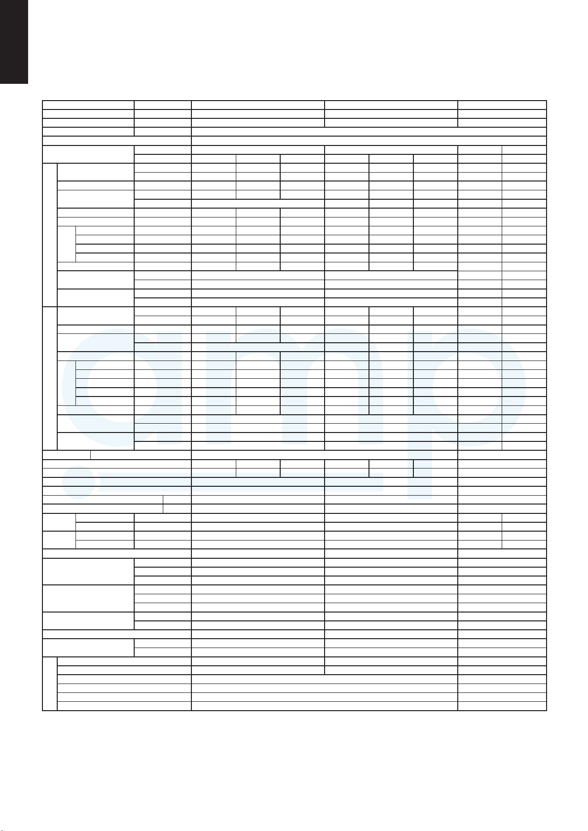
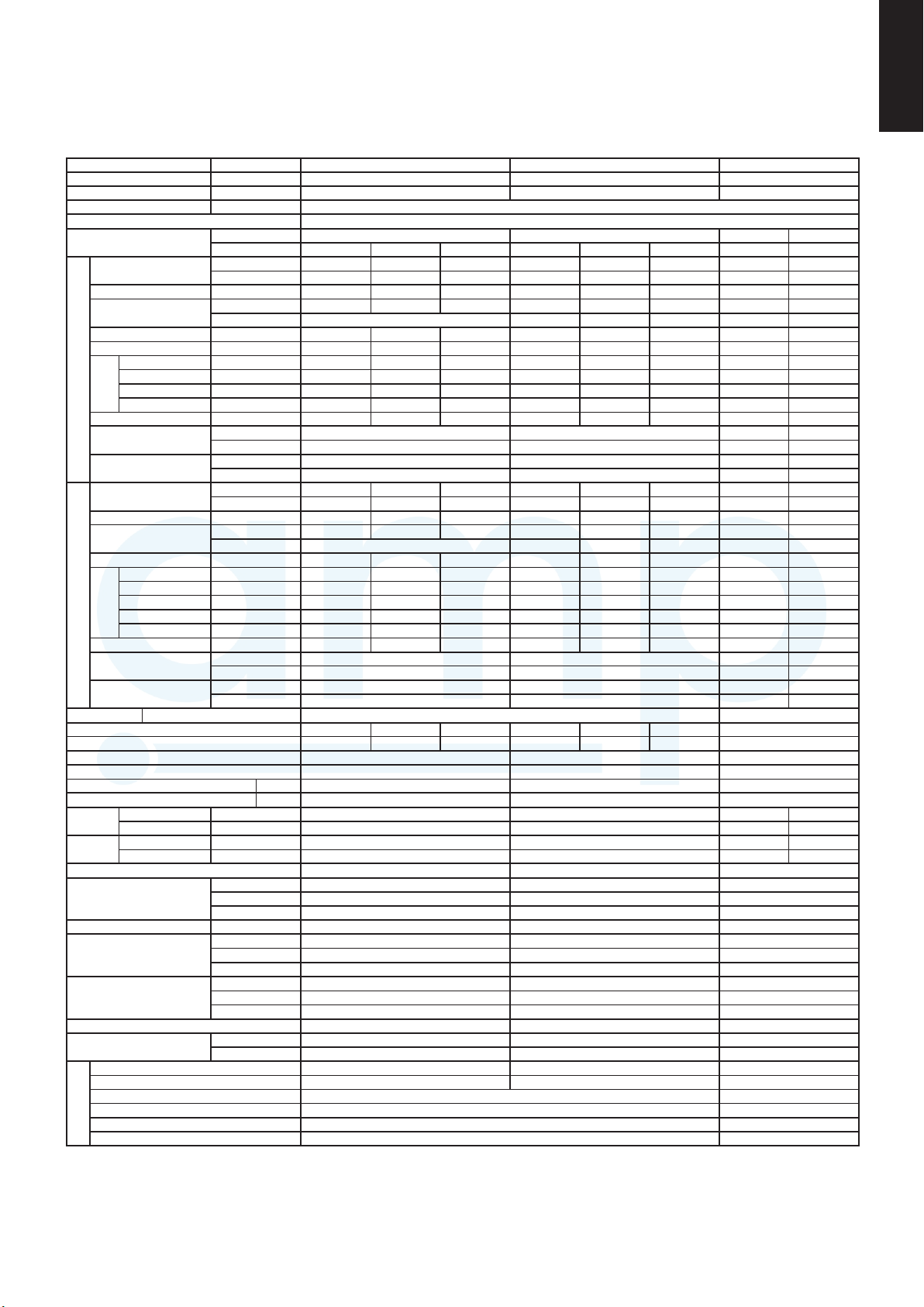
1-1. Unit Specications
High Static Pressure Ducted Type S-200PE2E5 / U-200PE2E8A
INDOOR MODEL S-200PE2E5 - -
PANEL MODEL - - -
OUTDOOR MODEL - U-200PE2E8A -
Branch pipe MODEL -
Performance test condition ISO13253 / EN14511 / EN12102
Power supply
Capacity
Current A 1.95 1.90 1.85 9.75 9.35 9.00 - -
Input power
C
Annual consumption TOTAL kWh *4 - - - - 3135 - - -
O
EER/EER CLASS
O
N
G
H
E
A
T
N
G
EXTRA LOW TEMP
Air ow
Outdoor
Air ow
P
P
N
G
*1 In case it is necessary to indicate the air ow volume in (l/s), the value in (m
*2 If the EUROVENT Certied models can be operated under the "extra-low" temperature condition, -7°C dry bulb and -8°C wet-bulb temperatures with rated voltage
*3 Network Impedance shall be applicable for EUROPE and CHINA models.
*4 The annual consumption is calculated by multiplying the input power at 230V(400V) by an average of 500 hours per year in cooling mode.
*5 EER and COP classication is at 230V(400V) only in accordance with EU directive 2002/31/EC.
*6 SEER and SCOP classication is at 230V(400V) only in accordance with EN-14825. For heating, SCOP indicates the value of only Average heating season,
Pdesign kW - - - - - - - -
L
SEER (W/W) - - - - - - - -
Erp
I
*6
Annual consumption
Class - - - - - - - -
Power factor % - - - 93 92 92 - -
Noise indoor
Noise outdoor
Capacity
Current A 1.95 1.90 1.85 9.85 9.45 9.10 - -
Input power
COP/COP CLASS
Pdesign at -10°C kW - - - - - - - Tbivalent °C - - - - - - - -
Erp
SCOP
I
*6
Annual consumption
Class - - - - - - - -
Power factor % - - - 93 92 92 - -
Noise indoor
Noise outdoor
Max Current(A) / Max Input power(W) 6.90/1.27k 6.60/1.27k 6.30/1.27k 20.0/12.2k 20.0/12.8k 20.0/13.2k Startring current(A) / Comp output(W) - - - 9.85/4.2k 9.45/4.2k 9.10/4.2k -
Fan motor output (Indoor/Outdoor) W 560 120 × 2 -
Indoor
Product dimension
Packing dimension
Operation condition
Connecting method, Standard length m (ft)
I
I
Indoor unit & Outdoor unit height difference m (ft)
230V shall be used.
Other che data indicates in an attached sheet.
Total capacity(kW)/Input power(W)/COP
Network Impedance(ΩMAX.) - - -
Moisture removal volume
External static pressure Pa 60 / (140/270) - -
Cooling
Heating
Cooling m
Heating m
Refrigerrant type / amount g(oz) - R410A 56.0k (197.5) -
Weight
Layers limit (actually) 4 (5) 1 (2) -
Pipe diameter mm (inch) (Liquid)Ø9.52(3/8) (Gas)Ø25.4(1) (Liquid)Ø9.52(3/8) (Gas)Ø25.4(1) -
Pipe length range m (ft) 5~120m (16.4~393.7) -
Add gas amount g/m (oz/ft) (Liquid)Ø9.52(3/8): 50g (0.54) -
Pipe length for additional gas m (ft) 30m (98.4) -
Ø, Hz 1Ø 50Hz 3Ø 50Hz
V 220V 230V 240V 380V 400V 415V Min Max
kW 19.5 19.5 19.5 - - - 5.4 22.4
BTU/h 66500 66500 66500 - - - 18400 76400
W 305 305 305 5.965k 5.965k 5.965k - -
TOTAL W - 6.270k 6.270k 6.270k - -
TOTAL (W/W) *5 / ("A"~"G")
kWh - - - - - - - -
dB-A (H/M/L) 43/41/38 - - -
Power Level dB 75/73/70 - - -
dB-A (H/L) - 60/- - -
Power Level dB - 78/- - -
kW 22.4 22.4 22.4 - - - 5.6 25.0
BTU/h 76400 76400 76400 - - - 19100 85300
W 305 305 305 6.015k 6.015k 6.015k - -
TOTAL W - 6.320k 6.320k 6.320k - -
TOTAL (W/W) *5/ ("A"~"G")
(W/W) - - - - - - - -
kWh - - - - - - - -
dB-A (H/M/L) 43/41/38 - - -
Power Level dB 75/73/70 - - -
dB-A (H/L) - 62/- - -
Power Level dB - 80/- - -
L/h(Pt/h)
m3/min (m3/h) (H/M/L)
m3/min (m3/h) (H/M/L)
3
/min (m3/h) - 164 (9840) - -
3
/min (m3/h) - 164 (9840) - -
Height
mm(inch)
mm(inch)
Width
mm(inch)
Depth
Height
mm(inch)
mm(inch)
Width
mm(inch)
Depth
(NET) kg(lb) 100 (221) 127 (280) -
(GROSS)
kg(lb) 132 (291) 139 (306) -
Cool (DBT) 18°C ~ 32°C -15°C ~ 46°C Heat (DBT) 16°C ~ 30°C -20°C ~ 24°C -
- - - 3.11 3.11/B 3.11 - -
- - - 3.54 3.54/B 3.54 - -
- -
11.1 (23.3) - -
56/51/44 (3360/3060/2640) - - 56/51/44 (3360/3060/2640) - - -
479 (18-27/32) 1500 (59-1/16) 1453 (57-7/32) 980 (38-37/64) 1205 (47-7/16) 370 (14-9/16) -
614 (24-3/16) 1642 (64-41/64) 1536 (60-15/32) 1095 (43-7/64) 1339 (52-23/32) 529 (20-53/64) -
(Liquid)&(Gas)brazing connection, 7.5(24.6)
30m(Outdoor unit located lower)/30m(Outdoor unit located higher) (98.4/98.4) -
3
/min.) shall be multiplied by 16.7 and rounded down the decimal point.
(Liquid)ared type (Gas)brazing connection, 7.5(24.6)
-
1-2

Single-Type
AMP Air Conditioning
www.ampair.co.uk | sales@ampair.co.uk
High Static Pressure Ducted Type S-250PE2E5 / U-250PE2E8A
INDOOR MODEL S-250PE2E5 - -
PANEL MODEL - - -
OUTDOOR MODEL - U-250PE2E8A -
Branch pipe MODEL -
Performance test condition ISO13253 / EN14511 / EN12102
Power supply
Capacity
Current A 3.30 3.20 3.10 13.0 12.5 12.0 - -
Input power
C
Annual consumption TOTAL kWh *4 - - - - 4300 - - -
O
EER/EER CLASS
O
N
G
H
E
A
T
N
G
EXTRA LOW TEMP
Air ow
Outdoor
Air ow
P
P
N
G
*1 In case it is necessary to indicate the air ow volume in (l/s), the value in (m
*2 If the EUROVENT Certied models can be operated under the "extra-low" temperature condition, -7°C dry bulb and -8°C wet-bulb temperatures with rated voltage
*3 Network Impedance shall be applicable for EUROPE and CHINA models.
*4 The annual consumption is calculated by multiplying the input power at 230V(400V) by an average of 500 hours per year in cooling mode.
*5 EER and COP classication is at 230V(400V) only in accordance with EU directive 2002/31/EC.
*6 SEER and SCOP classication is at 230V(400V) only in accordance with EN-14825. For heating, SCOP indicates the value of only Average heating season,
Pdesign kW - - - - - - - -
L
SEER (W/W) - - - - - - - -
Erp
I
*6
Annual consumption
Class - - - - - - - -
Power factor % - - - 94 93 93 - -
Noise indoor
Noise outdoor
Capacity
Current A 3.30 3.20 3.10 11.5 11.1 10.7 - -
Input power
COP/COP CLASS
Pdesign at -10°C kW - - - - - - - Tbivalent °C - - - - - - - -
Erp
SCOP
I
*6
Annual consumption
Class - - - - - - - -
Power factor % - - - 94 93 93 - -
Noise indoor
Noise outdoor
Max Current(A) / Max Input power(W) 7.30/1.66k 7.30/1.74k 7.30/1.81k 20.0/12.4k 20.0/12.9k 20.0/13.4k Startring current(A) / Comp output(W) - - - 13.0/5.5k 12.5/5.5k 12.0/5.5k -
Fan motor output (Indoor/Outdoor) W 750 120 × 2 -
Indoor
Product dimension
Packing dimension
Operation condition
Connecting method, Standard length m (ft)
I
I
Indoor unit & Outdoor unit height difference m (ft)
230V shall be used.
Other che data indicates in an attached sheet.
Total capacity(kW)/Input power(W)/COP
Network Impedance(ΩMAX.) - - -
Moisture removal volume
External static pressure Pa 72 / (140/270) - -
Cooling
Heating
Cooling m
Heating m
Refrigerrant type / amount g(oz) - R410A 6.4k (225.8) -
Weight
Layers limit (actually) 4 (5) 1 (2) -
Pipe diameter mm (inch) (Liquid)Ø12.7(1/2) (Gas)Ø25.4(1) (Liquid)Ø12.7(1/2) (Gas)Ø25.4(1) -
Pipe length range m (ft) 5~120m (16.4~393.7) -
Add gas amount g/m (oz/ft) (Liquid)Ø12.7(1/2): 80g (0.860) -
Pipe length for additional gas m (ft) 30m (98.4) -
Ø, Hz 1Ø 50Hz 3Ø 50Hz
V 220V 230V 240V 380V 400V 415V Min Max
kW 25.0 25.0 25.0 - - - 6.3 28.0
BTU/h 85300 85300 85300 - - - 21500 95500
W 560 560 560 8.040k 8.040k 8.040k - -
TOTAL W - 8.600k 8.600k 8.600k - -
TOTAL (W/W) *5 / ("A"~"G")
kWh - - - - - - - -
dB-A (H/M/L) 47/45/42 - - -
Power Level dB 79/77/74 - - -
dB-A (H/L) - 61/- - -
Power Level dB - 80/- - -
kW 28.0 28.0 28.0 - - - 7.1 31.5
BTU/h 95500 95500 95500 - - - 24200 107500
W 560 560 560 7.140k 7.140k 7.140k - -
TOTAL W - 7.700k 7.700k 7.700k - -
TOTAL (W/W) *5/ ("A"~"G")
(W/W) - - - - - - - -
kWh - - - - - - - -
dB-A (H/M/L) 47/45/42 - - -
Power Level dB 79/77/74 - - -
dB-A (H/L) - 63/- - -
Power Level dB - 82/- - -
L/h(Pt/h)
m3/min (m3/h) (H/M/L)
m3/min (m3/h) (H/M/L)
3
/min (m3/h) - 160 (9600) - -
3
/min (m3/h) - 160 (9600) - -
Height
mm(inch)
mm(inch)
Width
mm(inch)
Depth
Height
mm(inch)
mm(inch)
Width
mm(inch)
Depth
(NET) kg(lb) 104 (230) 138 (304) -
(GROSS)
kg(lb) 136 (300) 150 (331) -
Cool (DBT) 18°C ~ 32°C -15°C ~ 46°C Heat (DBT) 16°C ~ 30°C -20°C ~ 24°C -
- - - 2.91 2.91/C 2.91 - -
- - - 3.64 3.64/A 3.64 - -
- -
13.9 (29.2) - -
72/63/53 (4320/3780/3180) - - 72/63/53 (4320/3780/3180) - - -
479 (18-27/32) 1500 (59-1/16) 1453 (57-7/32) 980 (38-37/64) 1205 (47-7/16) 370 (14-9/16) -
614 (24-3/16) 1642 (64-41/64) 1536 (60-15/32) 1095 (43-7/64) 1339 (52-23/32) 529 (20-53/64) -
(Liquid)ared type (Gas)brazing connection, 7.5(24.6) (Liquid)ared type (Gas)brazing connection, 7.5(24.6)
30m(Outdoor unit located lower)/30m(Outdoor unit located higher) (98.4/98.4) -
3
/min.) shall be multiplied by 16.7 and rounded down the decimal point.
-
11
1-3

Twin-Type
AMP Air Conditioning
www.ampair.co.uk | sales@ampair.co.uk
4-Way Cassette Type S-100PU2E5A ×2 / U-200PE2E8A
INDOOR MODEL S-100PU2E5A×2 - -
PANEL MODEL
OUTDOOR MODEL - U-200PE2E8A -
Branch pipe MODEL -
Performance test condition ISO5151 / EN14511 / EN12102
Power supply
Capacity
Current A 0.82 ×2 0.79 ×2 0.76 ×2 9.70 9.30 9.00 - -
Input power
C
Annual consumption TOTAL kWh *4 - - - - 3020 - - -
O
EER/EER CLASS
O
N
G
H
E
A
T
N
G
EXTRA LOW TEMP
Air ow *7
Outdoor
Air ow
Product dimension (Panel) H×W×D
P
P
N
G
*1 In case it is necessary to indicate the air ow volume in (l/s), the value in (m
*2
*3 Network Impedance shall be applicable for EUROPE and CHINA models.
*4 The annual consumption is calculated by multiplying the input power at 230V(400V) by an average of 500 hours per year in cooling mode.
*5 EER and COP classication is at 230V(400V) only in accordance with EU directive 2002/31/EC.
*6 SEER and SCOP classication is at 230V(400V) only in accordance with EN-14825. For heating, SCOP indicates the value of only Average heating season,
*7 H: High at setting 5 stage (Level 5), M: Middle at setting 5 stage (Level 3), L: Low at setting 5 stage (Level 1)
Pdesign kW - - - - - - - -
L
SEER (W/W) - - - - - - - -
Erp
I
*6
Annual consumption
Class - - - - - - - -
Power factor % - - - 93 92 92 - -
Noise indoor
Noise outdoor
Capacity
Current A 0.81 ×2 0.78 ×2 0.75 ×2 8.55 8.20 7.90 - -
Input power
COP/COP CLASS
Pdesign at -10°C kW - - - - - - - Tbivalent °C - - - - - - - -
Erp
SCOP
I
*6
Annual consumption
Class - - - - - - - -
Power factor % - - - 92 91 91 - -
Noise indoor
Noise outdoor
Max Current(A) / Max Input power(W)
Startring current(A) / Comp output(W) - - - 9.70/4.2k 9.30/4.2k 9.0/4.2k -
Fan motor output (Indoor/Outdoor) W 90 120 × 2 -
Indoor
Product dimension
Packing dimension
Operation condition
Connecting method, Standard length m (ft) ared type, 7.5(24.6)
I
I
Indoor unit & Outdoor unit height difference m (ft)
If the EUROVENT Certied models can be operated under the "extra-low" temperature condition, -7°C dry bulb and -8°C wet-bulb temperatures with rated voltage 230V shall be used.
Other che data indicates in an attached sheet.
Total capacity(kW)/Input power(W)/COP
Network Impedance(ΩMAX.) - - -
Moisture removal volume
External static pressure Pa - - -
Cooling
Heating
Cooling m
Heating m
Refrigerrant type / amount g(oz) - R410A 5.60k (197.5) -
Weight
Layers limit (actually) 11 (12) 1 (2) -
Pipe diameter mm (inch) (Liquid)Ø9.52(3/8) (Gas)Ø15.88(5/8) (Liquid)Ø9.52(3/8) (Gas)Ø25.4(1) -
Pipe length range m (ft) 5~120m (16.4~393.7) -
Add gas amount g/m (oz/ft) (Liquid)Ø9.52(3/8): 50g (0.54) -
Pipe length for additional gas m (ft) 30m (98.4) -
Ø, Hz 1Ø 50Hz 3Ø 50Hz
V 220V 230V 240V 380V 400V 415V Min Max
kW 20.0 20.0 20.0 - - - 5.4 22.4
BTU/h 68200 68200 68200 - - - 18400 76400
W 100 ×2 100 ×2 100 ×2 5.940k 5.940k 5.940k - -
TOTAL W - 6.040k 6.040k 6.040k - -
TOTAL (W/W) *5 / ("A"~"G")
kWh - - - - - - - -
dB-A (H/M/L) *7 45/38/32 - - -
Power Level dB 60/53/47 - - -
dB-A (H/L) - 60/- - -
Power Level dB - 78/- - -
kW 22.4 22.4 22.4 - - - 5.6 25.0
BTU/h 76400 76400 76400 - - - 19100 85300
W 95 ×2 95 ×2 95 ×2 5.165k 5.165k 5.165k - -
TOTAL W - 5.260k 5.260k 5.260k - -
TOTAL (W/W) *5/ ("A"~"G")
(W/W) - - - - - - - -
kWh - - - - - - - -
dB-A (H/M/L) *7 45/38/32 - - -
Power Level dB 60/53/47 - - -
dB-A (H/L) - 62/- - -
Power Level dB - 80/- - -
m3/min (m3/h) (H/M/L)
m3/min (m3/h) (H/M/L)
3
/min (m3/h) - 164 (9840) - -
3
/min (m3/h) - 164 (9840) - -
Height
Width
Depth
Height
Width
Depth
(NET) kg(lb) 25 (55) 127 (280) (GROSS)
Panel (NET) kg(lb) 5 (11) - -
Cool (DBT) 18°C ~ 32°C -15°C ~ 46°C Heat (DBT) 16°C ~ 30°C -20°C ~ 24°C -
Standard type: CZ-KPU3 / ECONAVI type: CZ-KPU3A
- - - 3.31 3.31/A 3.31 - -
- - - 4.26 4.26/A 4.26 - -
0.82 ×2/ 100 ×2 0.79 ×2/ 100 ×2
L/h(Pt/h)
mm(inch)
mm(inch)
mm(inch)
mm(inch)
33.5×950×950 (1-11/32 × 37-13/32 × 37-13/32)
mm(inch)
mm(inch)
mm(inch)
kg(lb) 32 (71) 139 (306) -
5.4 (2.7×2) (11.3) - -
36/26/18×2 (2160/1560/1080 ×2) - - 36/26/18×2 (2160/1560/1080 ×2) - - -
319 (12-9/16) 1500 (59-1/16) 840 (33-5/64) 980 (38-37/64) 840 (33-5/64) 370 (14-9/16) -
365 (14-3/8) 1642 (64-41/64) 898 (35-3/8) 1095 (43-7/64) 898 (35-3/8) 529 (20-53/64) -
30m(Outdoor unit located lower)/30m(Outdoor unit located higher) (98.4/98.4) -
0.76 ×2/ 100 x2
3
/min.) shall be multiplied by 16.7 and rounded down the decimal point.
- -
20.0/12.2k 20.0/12.8k 20.0/13.2k -
(Liquid)ared type (Gas)brazing connection, 7.5(24.6)
- -
- -
1-4
-
Twin-Type
AMP Air Conditioning
www.ampair.co.uk | sales@ampair.co.uk
4-Way Cassette Type S-125PU2E5A ×2 / U-250PE2E8A
INDOOR MODEL S-125PU2E5A×2 - -
PANEL MODEL
OUTDOOR MODEL - U-250PE2E8A -
Branch pipe MODEL -
Performance test condition ISO5151 / EN14511 / EN12102
Power supply
Capacity
Current A 0.91 ×2 0.88 ×2 0.85 ×2 13.6 13.1 12.6 - -
Input power
C
Annual consumption TOTAL kWh *4 - - - - 4265 - - -
O
EER/EER CLASS
O
N
G
H
E
A
T
N
G
EXTRA LOW TEMP
Air ow *7
Outdoor
Air ow
Product dimension (Panel) H×W×D
P
P
N
G
*1 In case it is necessary to indicate the air ow volume in (l/s), the value in (m
*2
*3 Network Impedance shall be applicable for EUROPE and CHINA models.
*4 The annual consumption is calculated by multiplying the input power at 230V(400V) by an average of 500 hours per year in cooling mode.
*5 EER and COP classication is at 230V(400V) only in accordance with EU directive 2002/31/EC.
*6 SEER and SCOP classication is at 230V(400V) only in accordance with EN-14825. For heating, SCOP indicates the value of only Average heating season,
*7 H: High at setting 5 stage (Level 5), M: Middle at setting 5 stage (Level 3), L: Low at setting 5 stage (Level 1)
Pdesign kW - - - - - - - -
L
SEER (W/W) - - - - - - - -
Erp
I
*6
Annual consumption
Class - - - - - - - -
Power factor % - - - 94 93 93 - -
Noise indoor
Noise outdoor
Capacity
Current A 0.90 ×2 0.87 ×2 0.84 ×2 11.6 11.1 10.7 - -
Input power
COP/COP CLASS
Pdesign at -10°C kW - - - - - - - Tbivalent °C - - - - - - - -
Erp
SCOP
I
*6
Annual consumption
Class - - - - - - - -
Power factor % - - - 93 92 92 - -
Noise indoor
Noise outdoor
Max Current(A) / Max Input power(W)
Startring current(A) / Comp output(W) - - - 13.6/5.5k 13.1/5.5k 12.6/5.5k -
Fan motor output (Indoor/Outdoor) W 90 120 × 2 -
Indoor
Product dimension
Packing dimension
Operation condition
Connecting method, Standard length m (ft) ared type, 7.5(24.6)
I
I
Indoor unit & Outdoor unit height difference m (ft)
If the EUROVENT Certied models can be operated under the "extra-low" temperature condition, -7°C dry bulb and -8°C wet-bulb temperatures with rated voltage 230V shall be used.
Other che data indicates in an attached sheet.
Total capacity(kW)/Input power(W)/COP
Network Impedance(ΩMAX.) - - -
Moisture removal volume
External static pressure Pa - - -
Cooling
Heating
Cooling m
Heating m
Refrigerrant type / amount g(oz) - R410A 6.40k (225.8) -
Weight
Layers limit (actually) 11 (12) 1 (2) -
Pipe diameter mm (inch) (Liquid)Ø9.52(3/8) (Gas)Ø15.88(5/8) (Liquid)Ø12.7(1/2) (Gas)Ø25.4(1) -
Pipe length range m (ft) 5~120m (16.4~393.7) -
Add gas amount g/m (oz/ft) (Liquid)Ø12.7(1/2): 80g (0.860) -
Pipe length for additional gas m (ft) 30m (98.4) -
Ø, Hz 1Ø 50Hz 3Ø 50Hz
V 220V 230V 240V 380V 400V 415V Min Max
kW 25.0 25.0 25.0 - - - 6.3 28.0
BTU/h 85300 85300 85300 - - - 21500 95500
W 110 ×2 110 ×2 110 ×2 8.420k 8.420k 8.420k - -
TOTAL W - 8.530k 8.530k 8.530k - -
TOTAL (W/W) *5 / ("A"~"G")
kWh - - - - - - - -
dB-A (H/M/L) *7 46/39/33 - - -
Power Level dB 61/54/48 - - -
dB-A (H/L) - 61/- - -
Power Level dB - 80/- - -
kW 28.0 28.0 28.0 - - - 7.1 31.5
BTU/h 95500 95500 95500 - - - 24200 107500
W 105 ×2 105 ×2 105 ×2 7.095k 7.095k 7.095k - -
TOTAL W - 7.200k 7.200k 7.200k - -
TOTAL (W/W) *5/ ("A"~"G")
(W/W) - - - - - - - -
kWh - - - - - - - -
dB-A (H/M/L) *7 46/39/33 - - -
Power Level dB 61/54/48 - - -
dB-A (H/L) - 63/- - -
Power Level dB - 82/- - -
m3/min (m3/h) (H/M/L)
m3/min (m3/h) (H/M/L)
3
/min (m3/h) - 160 (9600) - -
3
/min (m3/h) - 160 (9600) - -
Height
Width
Depth
Height
Width
Depth
(NET) kg(lb) 25 (55) 138 (304) (GROSS)
Panel (NET) kg(lb) 5 (11) - -
Cool (DBT) 18°C ~ 32°C -15°C ~ 46°C Heat (DBT) 16°C ~ 30°C -20°C ~ 24°C -
Standard type: CZ-KPU3 / ECONAVI type: CZ-KPU3A
- - - 2.93 2.93/C 2.93 - -
- - - 3.89 3.89/A 3.89 - -
0.91 ×2/ 110 ×2 0.88 ×2/ 110 ×2
L/h(Pt/h)
mm(inch)
mm(inch)
mm(inch)
mm(inch)
33.5×950×950 (1-11/32 × 37-13/32 × 37-13/32)
mm(inch)
mm(inch)
mm(inch)
kg(lb) 32 (71) 150 (331) -
9.6 (4.8×2) (20.2) - -
37/27/19 ×2 (2220/1620/1140 ×2) - - 37/27/19 ×2 (2220/1620/1140 ×2) - - -
319 (12-9/16) 1500 (59-1/16) 840 (33-5/64) 980 (38-37/64) 840 (33-5/64) 370 (14-9/16) -
365 (14-3/8) 1642 (64-41/64) 898 (35-3/8) 1095 (43-7/64) 898 (35-3/8) 529 (20-53/64) -
30m(Outdoor unit located lower)/30m(Outdoor unit located higher) (98.4/98.4) -
0.85 ×2/ 110 ×2
3
/min.) shall be multiplied by 16.7 and rounded down the decimal point.
- -
20.0/12.4k 20.0/12.9k 20.0/13.4k -
(Liquid)ared type (Gas)brazing connection, 7.5(24.6)
- -
- -
1-5
-
11

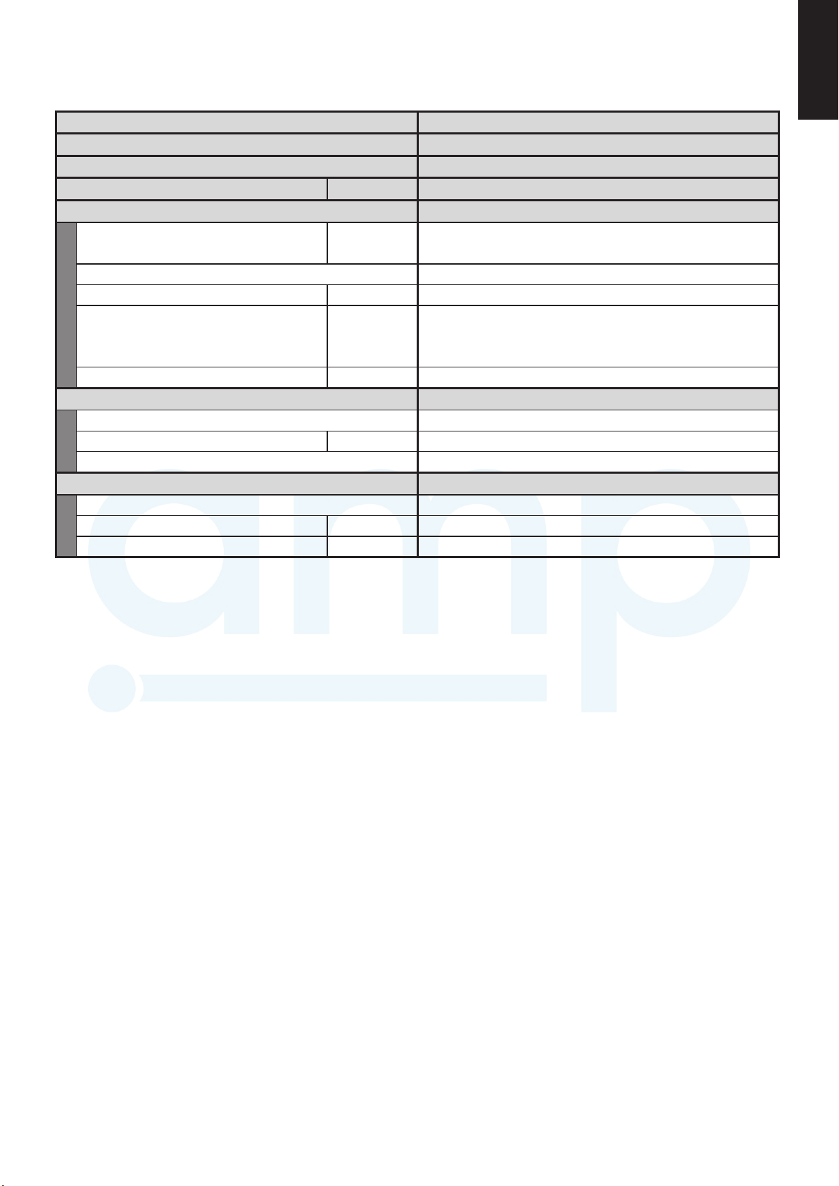
1-2. Major Component Specifications
AMP Air Conditioning
www.ampair.co.uk | sales@ampair.co.uk
(A) Indoor Units
High Static Pressure Ducted Type S-200PE2E5
MODEL No.
Source
Controller P.C.B. Ass'y
Fan (Number...diameter)
Fan motor
Power source
mm
WModel...Nominal output
rpmNo. of pole...r.p.m. (230V, High)
S-200PE2E5
220 - 230 - 240V, single-phase, 50Hz
CR-280ME2E5
SIROCCO (2...ø250)
DMUB6D1AC...560W
DMUB6D2AC...560W
100 - 391 VDC
8P...860
Coil resistance
(Ambient temperature 20°C)
Electronic expansion valve
Coil
Coil resistance (at 20°C)
Valve body
Heat exchanger
Coil
Ω
VAC, µFRun capacitor
Ω
Aluminium plate fin / Copper tube
mmRows...fin pitch
2
mFace area
–
–
–
–
–
3...1.8
0.648
1-6
(A) Indoor Units
AMP Air Conditioning
www.ampair.co.uk | sales@ampair.co.uk
High Static Pressure Ducted Type S-250PE2E5
MODEL No.
Source
Controller P.C.B. Ass'y
Fan (Number...diameter)
Fan motor
Power source
mm
WModel...Nominal output
rpmNo. of pole...r.p.m. (230V, High)
11
S-250PE2E5
220 - 230 - 240V, single-phase, 50Hz
CR-280ME2E5
SIROCCO (2...ø250)
DMUB8D1AC...560W
DMUB8D2AC...560W
100 - 391 VDC
8P...1020
Coil resistance
(Ambient temperature 20°C)
Electronic expansion valve
Coil
Coil resistance (at 20°C)
Valve body
Heat exchanger
Coil
Ω
VAC, µFRun capacitor
Ω
Aluminium plate fin / Copper tube
mmRows...fin pitch
2
mFace area
–
–
–
–
–
4...1.8
0.648
1-7

(A) Indoor Units
(A) Indoor Units
4-Way Cassette Type S-125PU2E5A
MODEL No.
S-125PU2E5A
Source
220 - 230 - 240 V, single-phase, 50 Hz
Controller P.C.B. Ass'y
ACXA73-02060(Microprocessor)
Fan (Number...diameter)
mm
Turbo (1...ø485)
Fan motor
SIC-72FW-D895-1…90W
280 VDC
rpm
8P…620
VAC, μF
overcurrent, rotating signal detection, fuse
Aluminium plate fin / Copper tube
mm
3...1.15
Face area
m
2
0.560
CZ-KPU3
MSBPC20A20
Coil resistance
Ω
300 Ω ± 7% / phase
PMD-12D13ST-7
V, W
DC 13 V, 4.2 W
Drain piping rise height from unit bottom, capacity
850 mm, 400 cc/min
Safety device
Model No.
Model...Nominal output
W
Power source
No. of pole...r.p.m. (230V, High)
Run capacitor
Rows...fin pitch
Heat exchanger
Coil
Rated
Auto louver motor
Drain pump
Panel
Model No.
AMP Air Conditioning
www.ampair.co.uk | sales@ampair.co.uk
4-Way Cassette Type S-100PU2E5A
MODEL No.
Source
Controller P.C.B. Ass'y
Fan (Number...diameter)
Fan motor
Model...Nominal output
Power source
No. of pole...r.p.m. (230V, High)
Run capacitor
Safety device
Heat exchanger
Coil
Rows...fin pitch
Face area
Panel
Model No.
Auto louver motor
Coil resistance
Drain pump
Model No.
Rated
Drain piping rise height from unit bottom, capacity
mm
W
rpm
VAC, μF
mm
2
m
Ω
V, W
S-100PU2E5A
220 - 230 - 240 V, single-phase, 50 Hz
ACXA73-02060(Microprocessor)
Turbo (1...ø485)
SIC-72FW-D895-1…90W
280 VDC
8P…600
overcurrent, rotating signal detection, fuse
Aluminium plate fin / Copper tube
3...1.15
0.560
CZ-KPU3
MSBPC20A20
300 Ω ± 7% / phase
PMD-12D13ST-7
DC 13 V, 4.2 W
850 mm, 400 cc/min
1-8

(A) Indoor Units
AMP Air Conditioning
www.ampair.co.uk | sales@ampair.co.uk
4-Way Cassette Type S-125PU2E5A
MODEL No.
Source
Controller P.C.B. Ass'y
Fan (Number...diameter)
Fan motor
mm
11
S-125PU2E5A
220 - 230 - 240 V, single-phase, 50 Hz
ACXA73-02060(Microprocessor)
Turbo (1...ø485)
Model...Nominal output
Power source
No. of pole...r.p.m. (230V, High)
Run capacitor
Safety device
Heat exchanger
Coil
Rows...fin pitch
Face area
Panel
Model No.
Auto louver motor
Coil resistance
Drain pump
Model No.
Rated
Drain piping rise height from unit bottom, capacity
W
rpm
VAC, μF
mm
2
m
Ω
V, W
SIC-72FW-D895-1…90W
280 VDC
8P…620
overcurrent, rotating signal detection, fuse
Aluminium plate fin / Copper tube
3...1.15
0.560
CZ-KPU3
MSBPC20A20
300 Ω ± 7% / phase
PMD-12D13ST-7
DC 13 V, 4.2 W
850 mm, 400 cc/min
1-9

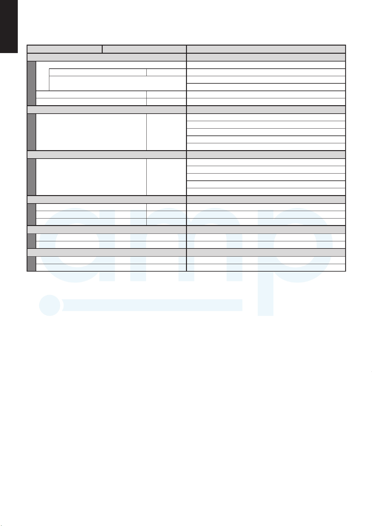
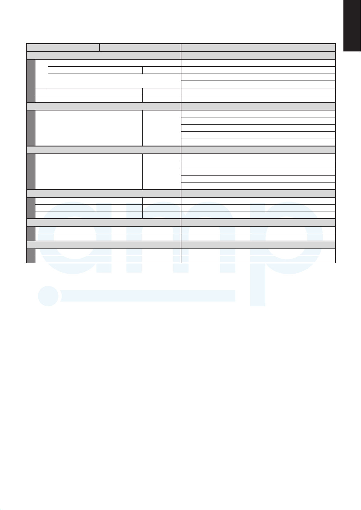
(B) Outdoor Units
(B) Outdoor Units
U-250PE2E8A
MODEL No.
Source
Controller P.C.B. Ass'y
Control circuit fuse
Compressor
Model....number
Source
WNominal output
ccCompressor oil
Coil resistance
(Ambient temperature 25°C)
Ω
U-V 0.678 U-W 0.700 V-W 0.691
Safety control
Overload relay models
Operation temperature
Open °C
Close °C
WCrank case heater
Refrigerant amount at shipment
kg
High pressure switch
Set pressure
MPaOFF 4.15
3.05±0.2MPa ON
Fan
mmNumber...diameter
m
3
/ hAir circulation
Fan speeds (Max.)
Fan motor
Model No.
Source
No. of pole
WNominal output
Safety device
Operating temperature
Open °C
Close °C
VAC, µF
Heat exchanger
Coil
mmRows...fin pitch
m
2
U-250PE2E8A
380/400/415V 3-Phase 50Hz
ACXA73C07260
30A
5JD650XDB22
520V DC MOTOR
5,500
2,050
Discharge temperature control
–
–
–
230V-36W
2...ø540
160
NFD-81FW-D8120-1,NFD-81FW-D8120-2
~280V / 1-phase
8
120
–
–
–
–
Aluminium plate fin / Copper tube
3..17FPI
1.367Face area
Run capacitor
+0
-0.2
AMP Air Conditioning
www.ampair.co.uk | sales@ampair.co.uk
U-200PE2E8A
MODEL No.
Source
Controller P.C.B. Ass'y
Control circuit fuse
Compressor
Model....number
Source
Coil resistance
(Ambient temperature 25°C)
Safety control
Refrigerant amount at shipment
High pressure switch
Overload relay models
Operation temperature
Set pressure
Fan
Fan speeds (Max.)
Fan motor
Model No.
Source
No. of pole
Safety device
Heat exchanger
Operating temperature
Run capacitor
Coil
Open °C
Close °C
Open °C
Close °C
VAC, µF
380/400/415V 3-Phase 50Hz
WNominal output
ccCompressor oil
Ω
U-V 0.678 U-W 0.700 V-W 0.691
Discharge temperature control
WCrank case heater
kg
MPaOFF 4.15
mmNumber...diameter
3
/ hAir circulation
m
WNominal output
NFD-81FW-D8120-1,NFD-81FW-D8120-2
Aluminium plate fin / Copper tube
mmRows...fin pitch
2
m
U-200PE2E8A
ACXA73C07280
30A
5JD650XDB22
520V DC MOTOR
4,200
2,050
–
–
–
230V-36W
+0
-0.2
3.05±0.2MPa ON
2...ø540
164
~280V / 1-phase
8
120
–
–
–
–
2..17FPI
1.367Face area
1-10

(B) Outdoor Units
AMP Air Conditioning
www.ampair.co.uk | sales@ampair.co.uk
U-250PE2E8A
MODEL No.
Source
Controller P.C.B. Ass'y
Control circuit fuse
Compressor
Model....number
Source
Coil resistance
(Ambient temperature 25°C)
Safety control
Overload relay models
Operation temperature
Refrigerant amount at shipment
High pressure switch
Set pressure
Fan
Fan speeds (Max.)
Fan motor
Model No.
Source
No. of pole
Safety device
Operating temperature
Run capacitor
Heat exchanger
Coil
Open °C
Close °C
Open °C
Close °C
VAC, µF
380/400/415V 3-Phase 50Hz
520V DC MOTOR
WNominal output
ccCompressor oil
Ω
WCrank case heater
kg
MPaOFF 4.15
mmNumber...diameter
3
/ hAir circulation
m
WNominal output
mmRows...fin pitch
2
m
U-V 0.678 U-W 0.700 V-W 0.691
Discharge temperature control
NFD-81FW-D8120-1,NFD-81FW-D8120-2
Aluminium plate fin / Copper tube
U-250PE2E8A
ACXA73C07260
30A
5JD650XDB22
5,500
2,050
–
–
–
230V-36W
+0
-0.2
3.05±0.2MPa ON
2...ø540
160
~280V / 1-phase
8
120
–
–
–
–
3..17FPI
1.367Face area
11
1-11
1-3. Other Component Specifications
Outdoor Units U-250PE2E8A
MODEL No.
Outdoor Unit
Power Transformer
Rated
VAC, HzSource
Secondary
Coil resistance
Ω
Thermistor (Coil / Air sensor): TH1, TH2, TH3, TH4
Resistance
kΩ
-20°C: 38.48±2% 20°C: 6.517±2%
-10°C: 23.67±2% 30°C: 4.448±2%
0°C: 15.00±2% 40°C: 3.100±2%
5°C: 12.06±2% 45°C: 2.607±2%
10°C: 9.765±2% 50°C: 2.203±2%
Thermistor (Discharge gas sensor): TH5
Resistance
kΩ
60°C: 1.593±2% 85°C: 0.7598±2%
65°C: 1.363±2% 90°C: 0.6623±2%
70°C: 1.171±2% 95°C: 0.5793±2%
75°C: 1.010±2% 100°C: 0.5083±2%
80°C: 0.8746±2% 105°C: 0.4473±2%
Relay (Comp. Magnetic Contactor)
VACCoil rated
VAC, AContact rating
Coil resistance (at 20°C)
Ω
Sol-Control-Valve
4 way valve
4 way valve
Electro magnetic coil
Thermal cut off temperature
Sol-control-valve
Magnetic coil
U-250PE2E8A
–
–
–
–
–
–
–
–
–
UKV32D322
SHF-35B-67-03
SQ-A2522G-005129 AC220-240V 50/60Hz
UKV-A392
AMP Air Conditioning
www.ampair.co.uk | sales@ampair.co.uk
Outdoor Units U-200PE2E8A
MODEL No.
Outdoor Unit
Power Transformer
Rated
VAC, HzSource
Secondary
Coil resistance
Thermal cut off temperature
Thermistor (Coil / Air sensor): TH1, TH2, TH3, TH4
Resistance
kΩ
Thermistor (Discharge gas sensor): TH5
Resistance
kΩ
Relay (Comp. Magnetic Contactor)
VACCoil rated
VAC, AContact rating
Coil resistance (at 20°C)
Sol-Control-Valve
Sol-control-valve
Magnetic coil
4 way valve
4 way valve
Electro magnetic coil
Ω
Ω
U-200PE2E8A
–
–
–
–
–
–
-20°C: 38.48±2% 20°C: 6.517±2%
-10°C: 23.67±2% 30°C: 4.448±2%
0°C: 15.00±2% 40°C: 3.100±2%
5°C: 12.06±2% 45°C: 2.607±2%
10°C: 9.765±2% 50°C: 2.203±2%
60°C: 1.593±2% 85°C: 0.7598±2%
65°C: 1.363±2% 90°C: 0.6623±2%
70°C: 1.171±2% 95°C: 0.5793±2%
75°C: 1.010±2% 100°C: 0.5083±2%
80°C: 0.8746±2% 105°C: 0.4473±2%
SQ-D23015-002283 DC15.4V(898mA)
–
–
–
UKV32D322
UKV-A392
SHF-20B-46-DC
1-12
Outdoor Units U-250PE2E8A
AMP Air Conditioning
www.ampair.co.uk | sales@ampair.co.uk
MODEL No.
Outdoor Unit
Power Transformer
Rated
VAC, HzSource
Secondary
Coil resistance
Thermal cut off temperature
Thermistor (Coil / Air sensor): TH1, TH2, TH3, TH4
Resistance
Thermistor (Discharge gas sensor): TH5
Resistance
Relay (Comp. Magnetic Contactor)
VACCoil rated
VAC, AContact rating
Coil resistance (at 20°C)
Sol-Control-Valve
Sol-control-valve
Magnetic coil
4 way valve
4 way valve
Electro magnetic coil
Ω
kΩ
kΩ
Ω
11
U-250PE2E8A
–
–
–
–
–
–
-20°C: 38.48±2% 20°C: 6.517±2%
-10°C: 23.67±2% 30°C: 4.448±2%
0°C: 15.00±2% 40°C: 3.100±2%
5°C: 12.06±2% 45°C: 2.607±2%
10°C: 9.765±2% 50°C: 2.203±2%
60°C: 1.593±2% 85°C: 0.7598±2%
65°C: 1.363±2% 90°C: 0.6623±2%
70°C: 1.171±2% 95°C: 0.5793±2%
75°C: 1.010±2% 100°C: 0.5083±2%
80°C: 0.8746±2% 105°C: 0.4473±2%
–
–
–
UKV32D322
UKV-A392
SHF-35B-67-03
SQ-A2522G-005129 AC220-240V 50/60Hz
1-13

1-4. Dimensional Data
AMP Air Conditioning
www.ampair.co.uk | sales@ampair.co.uk
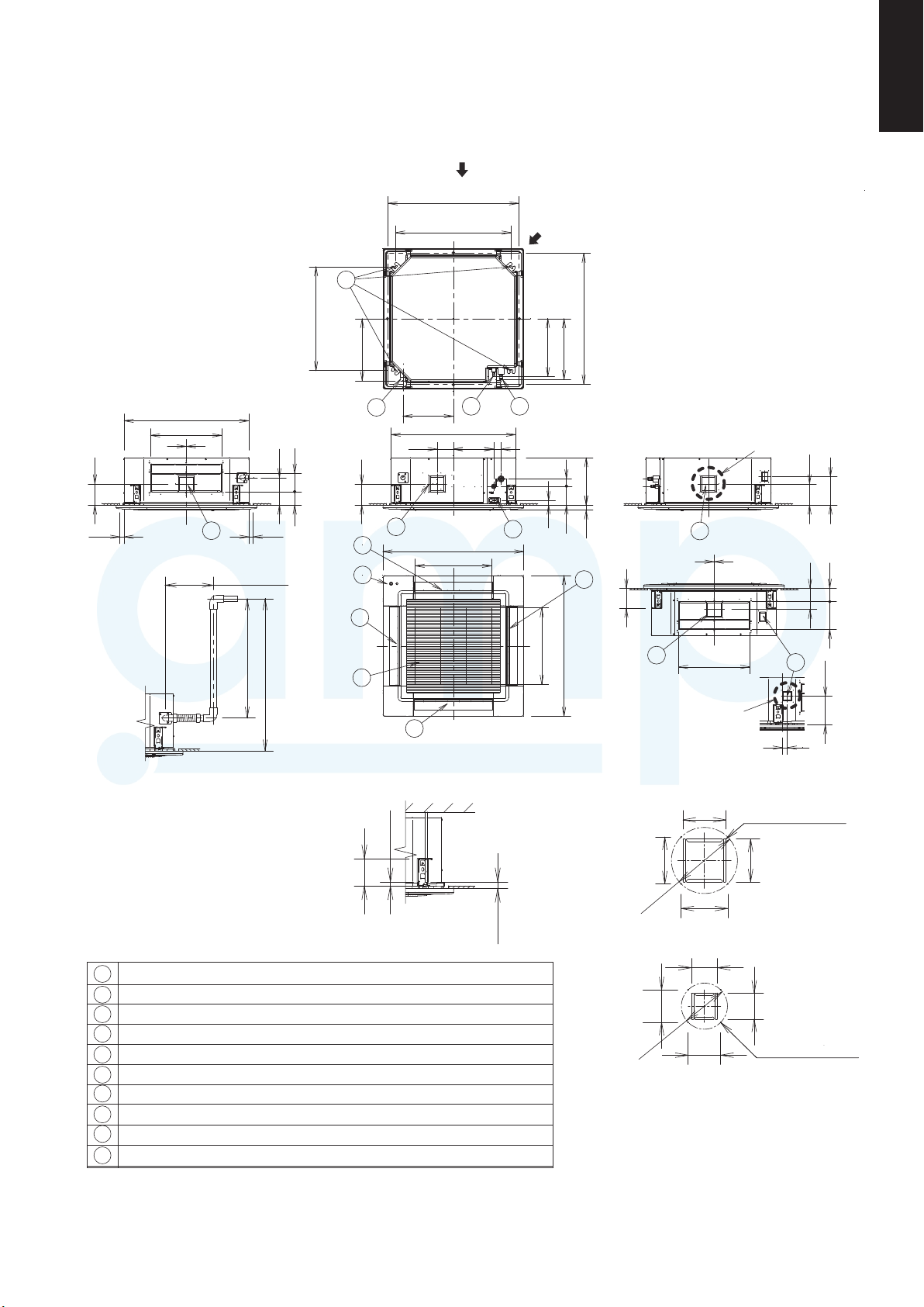
(A) Indoor Units: High Static Pressure Ducted Type
Required Minimum Space for Installation and Service
(1) Dimensions of suspension bolt pitch and unit
1170
(Suspension bolt pitch)
1100
Unit: mm
(60)(60)
Inspection access (600 × 600)(Field supply)
467
For power supply
wiring port
For
communication
wiring port
Port for
optional
wiring part
27
65
264
479
(2) Dimensions of indoor unit
Types 200 / 250
4-37×12 hole
(For suspension bolt)
28-ø3.2 hole
467
service)
Min. 600
(Space for
1070
1310
77
45
132
Drain
port
Refrigerant
tubing joint
Min. 800
(Space for service)
Min. 1100
(Space for service)
1138
467
7
(Suspension bolt pitch)
(60) (60)
1170
1100
* Space for removing
drain pan
1334
1453
964
67
1200
1310
Min. 610*
(Space for
service)
(Suspension bolt pitch)
67
200
Ceiling face
Electrical
component box
Inspection access (600 × 600)(Field supply)
Refrigerant liquid tubing (Flare)
1
(Type 200 : Connection Tubing ø12.7ø12.7 → ø9.52)
Refrigerant gas tubing (Brazing) ø25.4
2
Power supply port
3
Communication wiring port
422
8
4
Port for optional wiring part
5
Drain port 25A
6
Air intake duct connecting side flange
7
Air discharge duct connecting side flange
8
26-ø3.2 hole
67
Unit : mm
1070
4
1310
5
77
479
40
300
23
132
50
100
100
43
65
264
27
3
479
10 ×100 pitch = 1000
45
6
2
1
1220
156
45
131207
1205
1-14
964
1200
1310
9 ×100 pitch = 900
(Suspension bolt pitch)
67
100
Electrical component box
41
60
320
434
100
1334
1453
(A) Indoor Units: 4-Way Cassette Type
Dimensional Data
Indoor Units: S-100PU2E5A / S-125PU2E5A / S-140PE2U5A
AMP Air Conditioning
www.ampair.co.uk | sales@ampair.co.uk
S-100PU2E5A / S-125PU2E5A
860~910
(Ceiling opening dimensions)
(Suspension bolt pitch)
8
780
11
X
unit: mm
XX
840
480
2
143
7
Less than 300
Less than 666
Raise dimension of drain tube
184
90 124
Less than 35Less than 35
Less than 850
700
418
(Suspension bolt pitch)
5
143
2
10
2
1
860~910
(390)
(410)
(Ceiling opening dimensions)
340
3
840
272110
7
950
(Air intake)
515
4
51
319
32
6
127 50
33.5
7
2
134
950
(Air intake)
515
7
480
View X
Y
143
192
2
90
143
187
9
(192)
Z
2
35
View XX
The length of the suspension bolts
should be selected so that there is
a gap of 30 mm or more below the
lower surface of the ceiling (18 mm
122
Over 18
or more below the lower surface of
the main unit), as shown in the
figure at right. If the suspension
bolt is too long, it will contact
the ceiling panel and the unit
cannot be installed.
Air intake
1
Discharge outlet
2
Refrigerant tubing (liquid tube) ø9.52 (flared)
3
Refrigerant tubing (gas tube) ø15.88 (flared)
4
Drain tube connection port VP25 (outer dia. ø32)
5
Power supply port
6
7
Discharge duct connection port (ø150)
Suspension bolt hole (4-12×30 elongated hole)
8
Fresh air intake duct connection port (ø100) *
9
10
ECONAVI sensor (Only CZ-KPU3A)
Necessary to attach duct connecting flange(field supplyed).
*
<Filter dimension>
520 x 520 x 15
1-15
Over 30
105
115
∅162
115
Detailed view Y
64
80
∅113
80
Detailed view Z
4 - M4
Tapping screw holes
105
64
4 - M4
Tapping screw holes

(B) Outdoor Unit: U-200PE2E8A
1
2
3
4
5
6
7
8
Unit: mm
Mounting hole (4-R6.5),
anchor bolt : M10
Refrigerant tubing (liquid tube),
flared connection (ø12.7)
Refrigerant tubing (gas tube),
flared connection (ø19.05)*
1
Refrigerant tubing port
Electrical wiring port (ø13)
Electrical wiring port (ø22)
Electrical wiring port (ø27)
Electrical wiring port (ø35)
29
1500
980
35
60
30
36
82
48
39
121
469
Z VIEW
370
60
6089
35
82
48
39
121
4
5
6
7
8
5
6
7
8
4
A VIEW
62.5
5047.5
75.5
16
13
20
412.5
350160200230
160 660 160
(10)
170
370
36
980
4×ȭ32 holes (holes for drain)
330
1
A
Air-discharge
Air intake
7
5
6
4
8
Z VIEW
42 74
100
120
173
16
51
35
47
Air-discharge Air intake
When using a drain pipe, install the drain socket
(field supply) onto the drain port. Seal the other
drain port with the rubber cap.
Air intake
Air intake
(Gas piping connection) While the main gas side pipe is ø25.4,
since connecting the outdoor unit's 3-way valve requires a ø19.05
flare, please be sure to use standard accessories joint piping B or
A for connection (brazing), and connect as follows.
*1
Specifi cation for pipe connecting indoor unit to outdoor unit.
A8E2EP052-UModel name
Piping
Connections
12.7øedisdiuqiL
25.4øedissaG
(B) Outdoor Unit: U-250PE2E8A
2
3
12
AMP Air Conditioning
www.ampair.co.uk | sales@ampair.co.uk
Air intake
(10)
Air intake
37036
330
When using a drain pipe, install the drain socket
(field supply) onto the drain port. Seal the other
drain port with the rubber cap.
160 660 160
170
Air-discharge
4×ȭ32 holes (holes for drain)
980
980
Unit: mm
Mounting hole (4-R6.5),
1
anchor bolt : M10
Refrigerant tubing (liquid tube),
2
flared connection (ø9.52)
Refrigerant tubing (gas tube),
3
flared connection (ø19.05) *1
350160200230
A
412.5
20
13
1
1
*
4
Refrigerant tubing port
5
Electrical wiring port (ø13)
6
Electrical wiring port (ø22)
Electrical wiring port (ø27)
7
Electrical wiring port (ø35)
8
Specifi cation for pipe connecting indoor unit to outdoor unit.
Piping
Connections
(Gas piping connection) While the main gas side pipe is ø25.4,
since connecting the outdoor unit's 3-way valve requires a ø19.05
flare, please be sure to use standard accessories joint piping B or
A for connection (brazing), and connect as follows.
U-200PE2E8AModel name
370
25.9øedis diuqiL
25.4øedis saG
Air intake
1500
29
Air-discharge Air intake
2
3
5
43
48
39
82
35
60
6089
6
8
35
47
35
36
6
7
8
30
60
5
39
82
469
48
121
4
121
6
7
8
Z VIEW
4
5
7
A VIEW
62.5
5047.5
75.5 16
51
16
173
120
42 74
100
Z VIEW
4
1-16

11
AMP Air Conditioning
www.ampair.co.uk | sales@ampair.co.uk
(B) Outdoor Unit: U-250PE2E8A
Air intake
Air intake
(10)
370
330
36
When using a drain pipe, install the drain socket
(field supply) onto the drain port. Seal the other
drain port with the rubber cap.
160 660 160
170
Air-discharge
4×ȭ32 holes (holes for drain)
980
980
Mounting hole (4-R6.5),
Unit: mm
1
anchor bolt : M10
Refrigerant tubing (liquid tube),
2
flared connection (ø12.7)
Refrigerant tubing (gas tube),
3
350160200230
A
412.5
20
13
1
*1
flared connection (ø19.05)*
4
Refrigerant tubing port
5
Electrical wiring port (ø13)
6
Electrical wiring port (ø22)
Electrical wiring port (ø27)
7
Electrical wiring port (ø35)
8
Specifi cation for pipe connecting indoor unit to outdoor unit.
Piping
Connections
(Gas piping connection) While the main gas side pipe is ø25.4,
since connecting the outdoor unit's 3-way valve requires a ø19.05
flare, please be sure to use standard accessories joint piping B or
A for connection (brazing), and connect as follows.
1
A8E2EP052-UModel name
12.7øedisdiuqiL
25.4øedissaG
370
Air intake
1500
29
Air-discharge Air intake
2
3
5
12
48
35
39
82
60
6089
35
6
7
36
8
30
60
5
39
82
48
121
469
121
4
6
8
47
6
7
8
Z VIEW
4
5
7
35
A VIEW
62.5
16
5047.5
75.5
51
16
173
120
42 74
4
100
Z VIEW
1-17

High pressure
1-5. Refrigerant Flow Diagram
Ø 12.7
Ø 25.4
Ø
9.52
Indoor Unit : S-100PU2E5A×2Outdoor Unit : U-200PE2E8A
Indoor Unit : S-125PU2E5A×2Outdoor Unit : U-250PE2E8A
Muffler
Muffler
Gas line
service valve
Gas line
service valve
Expantion valve
Cooling cycle
Heating cycle
Cooling cycle
Heating cycle
StrainerStrainer
Strainer
Oil separater
Oil separater
Strainer
Capillary tube
Capillary tube
StrainerStrainer
Distributor
Distributor
Distributor
Branch pipe
Branch pipe
Distributor
Compressor
Compressor
High pressure
switch
High pressure
switch
Heat
exchanger
Heat
exchanger
Heat
exchanger
Heat
exchanger
Accumulator
Accumulator
4-way valve
2-way valve
2-way valve
4-way valve
Liquid line
service valve
Liquid line
service valve
Outdoor-air
Temp Thermistor
Outdoor-air
Temp Thermistor
Heat exchanger
Temp Thermistor
Heat exchanger
Temp Thermistor
Defrost Temp
Thermistor
Defrost Temp
Thermistor
Suction Temp
Thermistor
Suction Temp
Thermistor
Discharge Temp
Thermistor
Discharge Temp
Thermistor
Flare connection
Brazing connection
Brazing connection
Brazing connection
Cooling cycle
Heating cycle
Expantion valve
Ø 25.4
AMP Air Conditioning
www.ampair.co.uk | sales@ampair.co.uk
switch
Oil separater
Discharge Temp
Thermistor
Compressor
Strainer
Capillary tube
2-way valve
Suction Temp
Thermistor
Branch pipe
Accumulator
4-way valve
Muffler
Heat exchanger
Temp Thermistor
Heat
exchanger
Defrost Temp
Thermistor
Distributor
Expantion valve
Outdoor-air
Temp Thermistor
StrainerStrainer
Gas line
service valve
Liquid line
service valve
Ø 25.4
Brazing connection
Ø 9.52
Brazing connection
Indoor Unit : S-200PE2E5Outdoor Unit : U-200PE2E8A
Heat
exchanger
Distributor
Cooling cycle
Heating cycle
Cooling cycle
Heating cycle
Oil separater
Discharge Temp
Thermistor
Compressor
Strainer
Capillary tube
2-way valve
High pressure
switch
Branch pipe
4-way valve
Suction Temp
Thermistor
Accumulator
Muffler
Heat exchanger
Temp Thermistor
Heat
exchanger
Defrost Temp
Thermistor
Distributor
Expantion valve
Outdoor-air
Temp Thermistor
StrainerStrainer
Gas line
service valve
Liquid line
service valve
Ø 25.4
Brazing connection
Ø 12.7
Flare connection
Indoor Unit : S-250PE2E5Outdoor Unit : U-250PE2E8A
Heat
exchanger
Distributor
Cooling cycle
Heating cycle
1-18
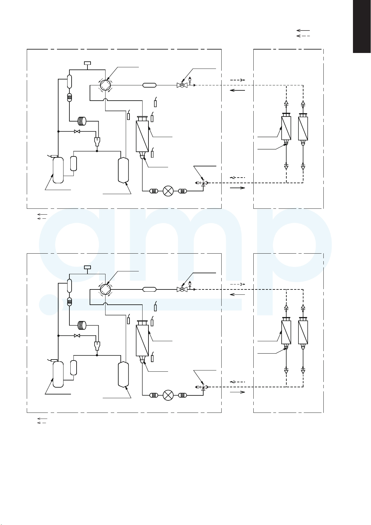
Oil separater
AMP Air Conditioning
www.ampair.co.uk | sales@ampair.co.uk
High pressure
switch
4-way valve
Muffler
Gas line
service valve
Ø 25.4
Brazing connection
Cooling cycle
11
Heating cycle
Indoor Unit : S-100PU2E5A×2Outdoor Unit : U-200PE2E8A
Discharge Temp
Thermistor
Compressor
Cooling cycle
Heating cycle
Oil separater
Strainer
Capillary tube
2-way valve
High pressure
switch
Suction Temp
Thermistor
Branch pipe
Accumulator
4-way valve
Heat exchanger
Temp Thermistor
Heat
exchanger
Defrost Temp
Thermistor
Distributor
Expantion valve
Muffler
Outdoor-air
Temp Thermistor
StrainerStrainer
Liquid line
service valve
Gas line
service valve
9.52
Ø
Brazing connection
Ø 25.4
Brazing connection
Indoor Unit : S-125PU2E5A×2Outdoor Unit : U-250PE2E8A
Heat
exchanger
Distributor
Discharge Temp
Thermistor
Compressor
Cooling cycle
Heating cycle
Strainer
Capillary tube
2-way valve
Suction Temp
Thermistor
Branch pipe
Accumulator
Outdoor-air
Temp Thermistor
Heat exchanger
Temp Thermistor
Heat
exchanger
Defrost Temp
Thermistor
Distributor
Expantion valve
StrainerStrainer
Liquid line
service valve
Ø 12.7
Flare connection
Heat
exchanger
Distributor
1-19

60
80
80
60
40
100
120
140
352515 455-15
100
120
-5 -105010-5
120
40
60
80
100
120
40
60
80
100
15 20 25-15-20
Input coefficient (%) Capacity coefficient (%)
Input coefficient (%) Capacity coefficient (%)
Cooling capacity ratio (maximum capacity) Heating capacity ratio (maximum capacity)
1-7. Capacity Correction Graph According to Temperature Condition
U-200PE2E8A / U-250PE2E8A (For 50 Hz)
Indoor air intake temp (WB)
22WB
19WB
16WB
22WB
19WB
16WB
Indoor air intake temp (WB)
Outdoor air intake temp (°C DB)
16
°C
20
°C
24
°C
Outdoor air intake temp (°C DB)
24
°C
20
°C
16
°C
1. The graphs " " of the characteristics show the value under the following conditions.
Equivalent tubing length : 7.5m
Difference of elevation : 0m
Wind speed: High
2. " " marking indicates the maximum capacity / maximum power consumption under the JIS condition.
Maximum capacity indicates the maximum value in the parentheses of the specifications (cooling and heating capacity).
3. The characteristic of heating capacity excludes the decline of capacity when frosting (including defrost drive).
NOTE 1
Indoor air intake temp (
°C
WB)
Indoor air intake temp (
°C
WB)
0.880.880.88 0.88 0.88 0.88 0.88 0.860.88 0.83 0.83 0.820.82 0.83 0.83
-20 -15 -10 -9 -8 -7 -6 -5 -4 -3 -2 -1
1.0
70126543
0.91 0.950.85 0.89
To calculate the heating capacity with consideration for frosting / defrosting operation, multiply the heating
capacity found from the capacity graph by the correction coefficient from the table above.
Outdoor unit heating capacity correction coefficient during of frosting / defrosting(RH approximately 85%)
Outdoor intake air
temperature
°C WB
Correction coefficient
1-6. Operating Range
AMP Air Conditioning
www.ampair.co.uk | sales@ampair.co.uk
S-200PE2E5 ─ U-200PE2E8A
S-250PE2E5 ─ U-250PE2E8A
Cooling
Heating
S-100PU2E5A ×2 ─ U-200PE2E8A
S-125PU2E5A ×2 ─ U-250PE2E8A
Cooling
Heating
Temperature Indoor air intake temp. Outdoor air intake temp.
Maximum 32°C DB 46°C DB
Minimum 18°C DB -15°C DB
Maximum 30°C DB 24°C DB
Temperature Indoor air intake temp. Outdoor air intake temp.
Minimum 16°C DB -20°C DB
Maximum 32°C DB 46°C DB
Minimum 18°C DB -15°C DB
Maximum 30°C DB 24°C DB
Minimum 16°C DB -20°C DB
1-20

1-7. Capacity Correction Graph According to Temperature Condition
AMP Air Conditioning
www.ampair.co.uk | sales@ampair.co.uk
U-200PE2E8A / U-250PE2E8A (For 50 Hz)
Cooling capacity ratio (maximum capacity) Heating capacity ratio (maximum capacity)
140
120
100
80
60
40
120
100
80
60
Input coefficient (%) Capacity coefficient (%)
NOTE 1
1. The graphs " " of the characteristics show the value under the following conditions.
Equivalent tubing length : 7.5m
Difference of elevation : 0m
Wind speed: High
2. " " marking indicates the maximum capacity / maximum power consumption under the JIS condition.
Maximum capacity indicates the maximum value in the parentheses of the specifications (cooling and heating capacity).
3. The characteristic of heating capacity excludes the decline of capacity when frosting (including defrost drive).
Indoor air intake temp (WB)
120
22WB
19WB
16WB
Indoor air intake temp (WB)
22WB
19WB
16WB
-5 -105010-5
352515 455-15
Outdoor air intake temp (°C DB)
100
80
60
40
120
100
80
60
40
Input coefficient (%) Capacity coefficient (%)
Outdoor air intake temp (°C DB)
Indoor air intake temp (
Indoor air intake temp (
11
WB)
°C
°C
15 20 25-15-20
WB)
16
°C
20
°C
24
°C
24
°C
20
°C
16
°C
Outdoor unit heating capacity correction coefficient during of frosting / defrosting(RH approximately 85%)
Outdoor intake air
temperature
°C WB
Correction coefficient
-20 -15 -10 -9 -8 -7 -6 -5 -4 -3 -2 -1
0.880.880.88 0.88 0.88 0.88 0.88 0.860.88 0.83 0.83 0.820.82 0.83 0.83
0.91 0.950.85 0.89
To calculate the heating capacity with consideration for frosting / defrosting operation, multiply the heating
capacity found from the capacity graph by the correction coefficient from the table above.
70126543
1.0
1-21

U-200PE2E8A
4-Way Cassette Type
REMARKS:
NOTE
1. Value obtained in the actual place where the unit is installed
may be slightly higher than the values shown in this graph
because of the conditions of operation, the structure of the
building, the background noise and other factors.
2. The test results were obtained from an anechoic room.
To evaluate “Noise level” the maximum number of the measured
OCTAVE BAND SOUND PRESSURE LEVEL is used.
Read the number on each BAND CENTER FREQUENCIES
(horizontal axis) ranging from 63 Hz to 8000 Hz and select the
maximum value (vertical axis) among them.
MODEL
SOUND LEVEL
CONDITION
SOURCE
: S-125PU2E5A
: High
Low
46 dB(A)
33 dB(A)
: Under the unit 1.5m
: 220-240V, 1 phase, 50Hz
MODEL
SOUND LEVEL
CONDITION
SOURCE
: S-100PU2E5A
: High
Low
45 dB(A)
32 dB(A)
: Under the unit 1.5m
: 220-240V, 1 phase, 50Hz
Octave Band Level (dB)
*0dB = 0.0002 µbar
Frequency at center of sound pressure band (Hz)
10
20
30
40
50
60
63 125250 5001000200040008000
NC-40
NC-60
NC-50
NC-30
NC-20
Approximate
minimum
audible limit
for continuous
noise
Octave Band Level (dB)
*0dB = 0.0002 µbar
Frequency at center of sound pressure band (Hz)
10
20
30
40
50
60
63 125250 5001000200040008000
NC-40
NC-50
NC-30
NC-20
NC-60
Approximate
minimum
audible limit
for continuous
noise
AMP Air Conditioning
www.ampair.co.uk | sales@ampair.co.uk
Rated capacity ratio for cooling Rated capacity ratio for heating
140
120
100
80
60
40
20
0
㻜㻌㻌㻌㻌㻌㻌㻌㻌㻌㻌㻡㻜㻜㻜㻌㻌㻌㻌㻌㻌㻝㻜㻜㻜㻜㻌㻌㻌㻌㻌㻝㻡㻜㻜㻜㻌㻌㻌㻌㻌㻌㻞㻜㻜㻜㻜㻌㻌㻌㻌㻌㻞㻡㻜㻜㻜
Power consumption ratio (%)
U-250PE2E8A
136% 133%
Capacity (W)
140
120
100
80
60
40
20
0
㻜㻌㻌㻌㻌㻌㻌㻌㻌㻌㻌㻡㻜㻜㻜㻌㻌㻌㻌㻌㻌㻝㻜㻜㻜㻜㻌㻌㻌㻌㻌㻝㻡㻜㻜㻜㻌㻌㻌㻌㻌㻌㻞㻜㻜㻜㻜㻌㻌㻌㻌㻌㻞㻡㻜㻜㻜㻌㻌㻌㻌㻌㻟㻜㻜㻜㻜
Power consumption ratio (%)
Capacity (W)
Rated capacity ratio for cooling Rated capacity ratio for heating
140
120
100
80
60
40
20
0
㻜㻌㻌㻌㻌㻌㻌㻌㻌㻌㻌㻡㻜㻜㻜㻌㻌㻌㻌㻌㻌㻝㻜㻜㻜㻜㻌㻌㻌㻌㻌㻝㻡㻜㻜㻜㻌㻌㻌㻌㻌㻌㻞㻜㻜㻜㻜㻌㻌㻌㻌㻌㻞㻡㻜㻜㻜㻌㻌㻌㻌㻌㻟㻜㻜㻜㻜
Power consumption ratio (%)
134% 135%
Capacity (W)
140
120
100
80
60
40
20
0
㻜㻌㻌㻌㻌㻌㻌㻌㻌㻡㻜㻜㻜㻌㻌㻌㻌㻝㻜㻜㻜㻜㻌㻌㻌㻝㻡㻜㻜㻜㻌㻌㻌㻌㻞㻜㻜㻜㻜㻌㻌㻌㻞㻡㻜㻜㻜㻌㻌㻌㻌㻟㻜㻜㻜㻜㻌㻌㻟㻡㻜㻜㻜
Power consumption ratio (%)
Capacity (W)
NOTE 2
1. The graphs " " of the characteristics show the value under the following conditions.
Equivalent tubing length : 7.5m
Difference of elevation : 0m
Wind speed : High
" marking indicates the rated capacity / rated power consumption under the JIS condition.
2. "
" " marking indicates the maximum capacity / maximum power consumption under the JIS condition.
3. The characteristic of heating capacity excludes the decline of capacity when frosting (including defrost drive).
1-22

1-8. Noise Criterion Curves
AMP Air Conditioning
www.ampair.co.uk | sales@ampair.co.uk
11
1
High Static Pressure Ducted Type
MODEL
SOUND LEVEL
CONDITION
90
80
70
60
50
40
30
20
Sound pressure level (dB) (0dB = 0.0002µbar)
10
63
: S-200PE2E5
: HIGH
LOW
43 dB(A)
38 dB(A)
: Under the unit 1.5 m
Approximate
minimum
audible limit for
continuous noise
125
Frequency at center of sound pressure band (Hz)
500 1000 2000 4000 8000250
NC-70
NC-60
NC-50
NC-40
NC-30
NC-20
MODEL
SOUND LEVEL
: S-250PE2E5
: HIGH
LOW
CONDITION
90
80
70
60
50
40
30
20
Sound pressure level (dB) (0dB = 0.0002µbar)
10
: Under the unit 1.5 m
Approximate
minimum
audible limit for
continuous noise
63
125
Frequency at center of sound pressure band (Hz)
HIGH
LOW
47 dB(A)
42 dB(A)
NC-70
NC-60
NC-50
NC-40
NC-30
NC-20
500 1000 2000 4000 8000250
4-Way Cassette Type
MODEL
SOUND LEVEL
CONDITION
SOURCE
60
50
40
30
Approximate
Octave Band Level (dB)
*0dB = 0.0002 µbar
minimum
20
audible limit
for continuous
noise
10
63 125250 5001000200040008000
Frequency at center of sound pressure band (Hz)
: S-100PU2E5A
Low
45 dB(A)
32 dB(A)
: High
: Under the unit 1.5m
: 220-240V, 1 phase, 50Hz
NC-60
NC-50
NC-40
NC-30
NC-20
MODEL
SOUND LEVEL
CONDITION
SOURCE
60
50
40
30
Approximate
Octave Band Level (dB)
*0dB = 0.0002 µbar
minimum
20
audible limit
for continuous
noise
10
63 125250 5001000200040008000
Frequency at center of sound pressure band (Hz)
: S-125PU2E5A
: High
: Under the unit 1.5m
: 220-240V, 1 phase, 50Hz
Low
46 dB(A)
33 dB(A)
NC-60
NC-50
NC-40
NC-30
NC-20
REMARKS:
1. Value obtained in the actual place where the unit is installed
may be slightly higher than the values shown in this graph
because of the conditions of operation, the structure of the
building, the background noise and other factors.
2. The test results were obtained from an anechoic room.
NOTE
To evaluate “Noise level” the maximum number of the measured
OCTAVE BAND SOUND PRESSURE LEVEL is used.
Read the number on each BAND CENTER FREQUENCIES
(horizontal axis) ranging from 63 Hz to 8000 Hz and select the
maximum value (vertical axis) among them.
1-23

COOLING
AMP Air Conditioning
www.ampair.co.uk | sales@ampair.co.uk
HEATING
MODEL
SOUND LEVEL
CONDITION
: U-200PE2E8A
: 60 dB(A)
: 1 m in front at height of 1.5 m
90
80
70
60
50
40
30
Approximate
Octave Band Level (dB)
(0dB = 0.0002 µbar)
20
minimum
audible limit for
continuous noise
10
Overall
4000000805252136 20001000500
Frequency at center of sound pressure band (Hz)
COOLING
NC-70
NC-60
NC-50
NC-40
NC-30
NC-20
MODEL
SOUND LEVEL
CONDITION
: U-200PE2E8A
: 62 dB(A)
: 1 m in front at height of 1.5 m
90
80
70
60
50
40
30
Approximate
Octave Band Level (dB)
(0dB = 0.0002 µbar)
20
minimum
audible limit for
continuous noise
10
Overall
4000000805252136 20001000500
Frequency at center of sound pressure band (Hz)
HEATING
NC-70
NC-60
NC-50
NC-40
NC-30
NC-20
MODEL
SOUND LEVEL
CONDITION
: U-250PE2E8A
: 61 dB(A)
: 1 m in front at height of 1.5 m
90
80
70
60
50
NC-70
NC-60
NC-50
40
NC-40
30
NC-30
Approximate
Octave Band Level (dB)
(0dB = 0.0002 µbar)
20
minimum
audible limit for
continuous noise
10
Overall
4000000805252136 20001000500
NC-20
Frequency at center of sound pressure band (Hz)
REMARKS:
1. Value obtained in the actual place where the unit is installed
may be slightly higher than the values shown in this graph
because of the conditions of operation, the structure of the
building, the background noise and other factors.
2. The test results were obtained from an nechoic room.
MODEL
SOUND LEVEL
CONDITION
: U-250PE2E8A
: 63 dB(A)
: 1 m in front at height of 1.5 m
90
80
70
60
50
NC-70
NC-60
NC-50
40
NC-40
30
NC-30
Approximate
Octave Band Level (dB)
(0dB = 0.0002 µbar)
20
minimum
audible limit for
continuous noise
10
Overall
4000000805252136 20001000500
NC-20
Frequency at center of sound pressure band (Hz)
NOTE
To evaluate “Noise level” the maximum number of the measured
OCTAVE BAND SOUND PRESSURE LEVEL is used.
Read the number on each BAND CENTER FREQUENCIES
(horizontal axis) ranging from 63 Hz to 8000 Hz and select the
maximum value (vertical axis) among them.
1-24
 Loading...