

Panasonic RXES-29-GC, RXES-29-GT, RXES-29-GS Service manual
A
r
r
A
A
Portable Stereo CD System
RX-ES29GC
RX-ES29GS
RX-ES29GT
Colour
(S)..........Silver Type
Order No. MD0503060C3
Specification
n RADIO
Frequency range
FM 87.50-108.00 MHz (50 kHz steps)
M 522-1629 kHz (9 kHz steps)
520-1630 kHz (10 kHz steps)
n CD PLAYER
Sampling frequency 44.1 kHz
Decoding 16 bit linea
Beam source Semiconductor laser (wavelength
780 nm)
No. of channels 2 channel, stereo
Wow and flutter Below measurable limit
D/A converter MASH (1 bit DAC)
n TAPE RECORDER
Track system Stereo
Monitor system Variable sound monito
Recording system AC bias
Erasing system Multi Pole magnet
Frequency range
Normal position 50-14000 Hz
n GENERAL
Speakers 8cm5.4Ω x2
Jacks
Output Phones: 3.5 mm stereo (16-32Ω )
Power requirement (For GC/GS)
C 110-127 V / 220-240 V, 50/60 Hz
Power consumption 33 W
Power requirement (For GT)
C 110V,60Hz
Power consumption 32 W
Battery 12 V [Eight R20/LR20 (D, UM-1)
batteries]
l Do not use rechargeable type batteries
Memory backup for
computer/clock
l Do not use rechargeable type batteries
Dimensions 529 mm (W) x 144 mm (H) x 276
Mass (For GC/GS) 4.4 kg without batteries
Mass (For GT) 4.2 kg without batteries
Power consumption in standby
mode (For GC/GS)
Power consumption in standby
mode (For GT)
Notes:
1. Specifications are subject to change without notice.
2. Mass and dimensions are approximate.
6 V [Four R6/LR6 (AA, UM-3)
batteries]
mm (D)
3.0 W (117 V)
3.5W (240 V)
2.7 W
© 2005 Matsushita Electric Industrial Co. Ltd.. All
rights reserved. Unauthorized copyin g and
distribution is a violation of law.
RX-ES29GC / RX-ES29GS / RX-ES29GT
CONTENTS
Page Page
1 Safety Precautions 3
1.1. GENERAL GUIDELINES
2 Caution for AC Mains Lead
3 Before Use
4 Before Repair and Adjustment
5 Protection Circuitry
6 Handling the Lead Solder
6.1. About lead free solder (PbF)
7 Precaution of Laser Diode
8 Handling Precautions For Traverse Deck
9 Accessories
10 Operation Procedures
10.1. Main unit
10.2. Remote control
11 Information on MP3
12 Disassembly and Main Component Replacement Procedures
and Operational Check
12.1. Disassembly procedures
12.2. Disassembly flow chart
12.3. Checking Procedure for each major P.C.B.
12.4. Procedures for Replacing Pinch Roller and Head Block
(Deck Mechanism Unit)
12.5. Procedures for Replacing Motor, Capstan Belt A, Capstan
Belt B, and Winding Belt (Deck Mechanism Unit)
12.6. Procedures for Replacing Parts on Deck Mechanism PCB
12.7. Procedures of Replacing Traverse Base (Unit), Driving
Gear, and Cam Gear (CD Mechanism Unit)
12.8. Procedures for Replacing Optical Pickup (CD Mechanism
Unit)
12.9. Procedures for Replacement Traverse Gear A and
Traverse Gear B (CD Mechanism Unit)
13 Procedure for checking of the major P.C.B.
13.1. Checking the Main P.C.B., Panel P.C.B., Deck Mechanism
P.C.B., CD Servo P.C.B., Battery P.C.B., Sensor P.C.B.,
Power-On P.C.B., Power and Standby LED P.C.B.
14 Self Diagnostic Function
10
11
12
12
12
13
21
21
23
23
26
27
29
29
30
3
4
5
5
5
5
5
6
7
8
9
9
14.1. Self-diagnosis Function 30
14.2. Setting of doctor mode
15 Measurements and Adjustments
15.1. Tuner Section
15.2. Deck Section
16 Voltage Measurement
16.1. CD Servo P.C.B.
16.2. Main P.C.B.
17 Waveform Chart
18 Notes of Schematic Diagram
19 Schematic Diagram
19.1. CD SERVO CIRCUIT
19.2. MAIN CIRCUIT and POWER ON CIRCUIT
19.3. MAIN (TUNER) CIRCUIT
19.4. MAIN (DECK) CIRCUIT and DECK MECHANISM
CIRCUIT
19.5. PANEL CIRCUIT, STANDBY LED CIRCUIT, BATTERY
CIRCUIT, POWER CIRCUIT and SENSOR CIRCUIT
20 Printed Circuit Board
20.1. CD SERVO P.C.B.
20.2. MAIN P.C.B.
20.3. PANEL P.C.B. and DECK MECHANISM P.C.B.
20.4. STANDBY LED P.C.B, BATTERY P.C.B, POWER ON
P.C.B and SENSOR P.C.B
20.5. POWER P.C.B.
21 Wiring Connection Diagram
22 Type Illustration of IC 痴, Transistors and Diodes
23 Terminal Function Of IC 痴
23.1. IC801 (MN101C74GAA2): Microprocessor
24 Troubleshooting Flowchart (CD Section Circuit)
25 Parts Location and Replacement Parts List
25.1. Deck Mechanism (RAA4401-1V)
25.2. CD Loading Mechanism
25.3. Cabinet Part List
25.4. Electrical Part List
25.5. Packaging Materials & Accessories Parts List
25.6. Packaging
32
38
38
39
41
41
42
44
45
46
46
48
55
57
59
60
60
61
63
64
65
66
68
69
69
70
72
73
75
77
79
85
85
2
RX-ES29GC / RX-ES29GS / RX- ES29GT
1 Safety Precautions
1.1. GENERAL GUIDELINES
1. When servicing, observe the original lead dress. If a short circuit is found, replace all parts which have been overheated or
damaged by the short circuit.
2. After servicing, ensure that all the protective devices such as insulation barriers, insulation papers shields are properly installed.
3. After servicing, check for leakage current checks to prevent from being exposed to shock hazards.
1.1.1. LEAKAGE CURRENT COLD CHECK
1. Unplug the AC cord and connect a jumper between the two prongs on the plug.
2. Using an ohmmeter measure the resistance value, between the jumpered AC plug and each exposed metallic cabinet part on
the equipment such as screwheads, connectors, control shafts, etc. When the exposed metallic part has a return path to the
chassis, the reading should be between 1MΩ and 5.2Ω.
When the exposed metal does not have a return path to the chassis, the reading must be
.
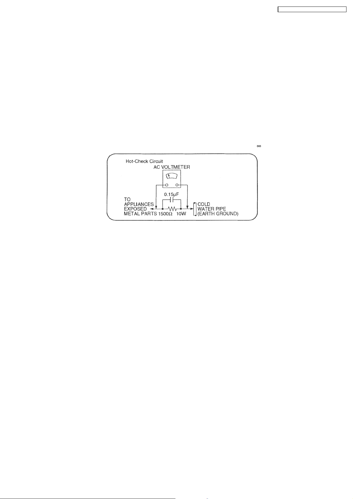
Fig. 1
1.1.2. LEAKAGE CURRENT HOT CHECK (See Figure 1.)
1. Plug the AC cord directly into the AC outlet. Do not use an isolation transformer for this check.
2. Connect a 1.5kΩ, 10 watts resistor, in parallel with a 0.15µF capacitors, between each exposed metallic part on the set and a
good earth ground such as a water pipe, as shown in Figure 1.
3. Use an AC voltmeter, with 1000 ohms/volt or more sensitivity, to measure the potential across the resistor.
4. Check each exposed metallic part, and measure the voltage at each point.
5. Reverse the AC plug in the AC outlet and repeat each of the above measurements.
6. The potential at any point should not exceed 0.75 volts RMS. A leakage current tester (Simpson Model 229 or equivalent) may
be used to make the hot checks, leakage current must not exceed 1/2 milliamp. Should the measurement is outside of the limits
specified, there is a possibility of a shock hazard, and the equipment should be repaired and re-checked before it is returned
to the customer.
3
RX-ES29GC / RX-ES29GS / RX- ES29GT
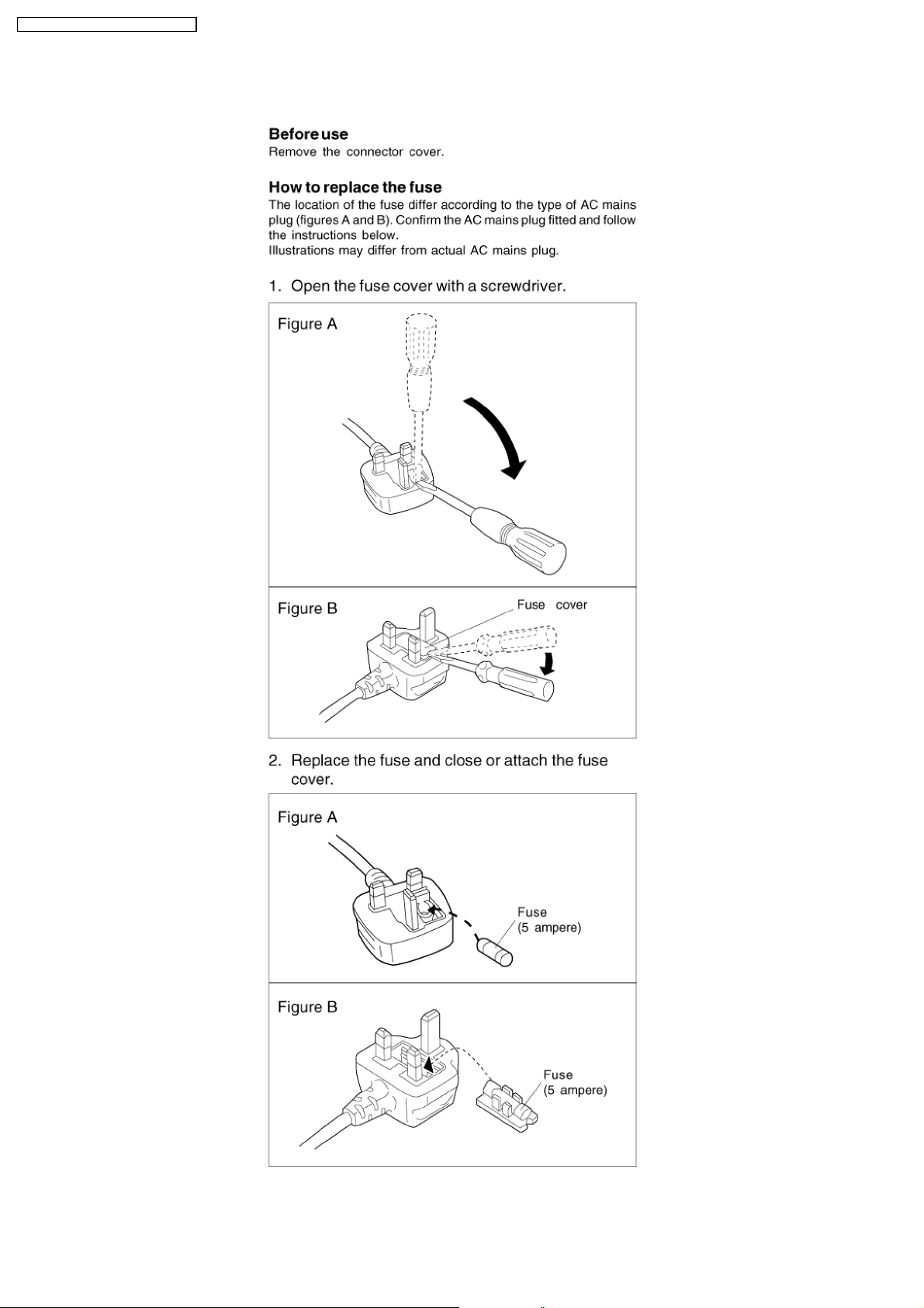
2 Caution for AC Mains Lead
4

RX-ES29GC / RX-ES29GS / RX- ES29GT
3 Before Use
Be sure to disconnect the mains cord before adjusting the voltage selector. Use a minus (-) screwdriver to set the voltage selector
(on the rear panel) to the voltage setting for the area in which the unit will be used.
(If the power supply in your area is 117V or 120V, set to the “127V” position.)
Note that this unit will be seriously damaged if this setting is not made correctly. (There is no voltage selector for some countries;
the correct voltage is already set.)
4 Before Repair and Adjustment
Disconnect AC power, discharge Power Supply Capacitors C131, C231, C301, C307, C309, C310 and C331 through a 10 Ω,1W
resistor to ground. DO NOT SHORT-CIRCUIT DIRECTLY (with a screw driver blade, for instance), as this may destroy solid state
devices.
After repairs are completed, restore power gradually using a variac, to avoid overcurrent.
( For GC/GS) Current consumption at AC 220-240 V / 117 V, 50/60 Hz in NO SIGNAL mode should be ~180 mA, ~200mA
respectively.
(For GT) Current consumption at AC 110 V, 60 Hz in NO SIGNAL mode should be ~150 mA respectively.
5 Protection Circuitry
The protection circuitry may have operated if either of the following conditions are noticed:
· No sound is heard when the power is turned on.
· Stops during a performance.
The function of this circuitry is to prevent circuitry damage if, for example, the positive and negative speaker connection wires are
“shorted”, or if speaker systems with an impedance less than the indicated rated impedance of the amplifier are used.
If this occurs, follow the procedure outlines below:
1. Turn off the power.
2. Determine the cause of the problem and correct it.
3. Turn on the power once again after one minute.
Note:
When the protection circuitry functions, the unit will not operate unless the power is first turned off and then on again.
6 Handling the Lead Solder
6.1. About lead free solder (PbF)
Distinction of PbF P.C.B. :
P.C.B.s (manufactured) using lead free solder will have a PbF stamp on the P.C.B.
Caution:
· Pb free solder has a higher melting point than standard solder; Typically the melting point is 50 - 70°F (30 - 40°C) higher.
Please use a high temperature soldering iron. In case of the soldering iron with temperature control, please set it to 700 ± 20°F
(370 ± 10°C).
· Pb free solder will tend to splash when heated too high (about 1100°F/600°C).
· When soldering or unsoldering, please completely remove all of the solder on the pins or solder area, and be sure to heat the
soldering points with the Pb free solder until it melts enough.
5
RX-ES29GC / RX-ES29GS / RX- ES29GT
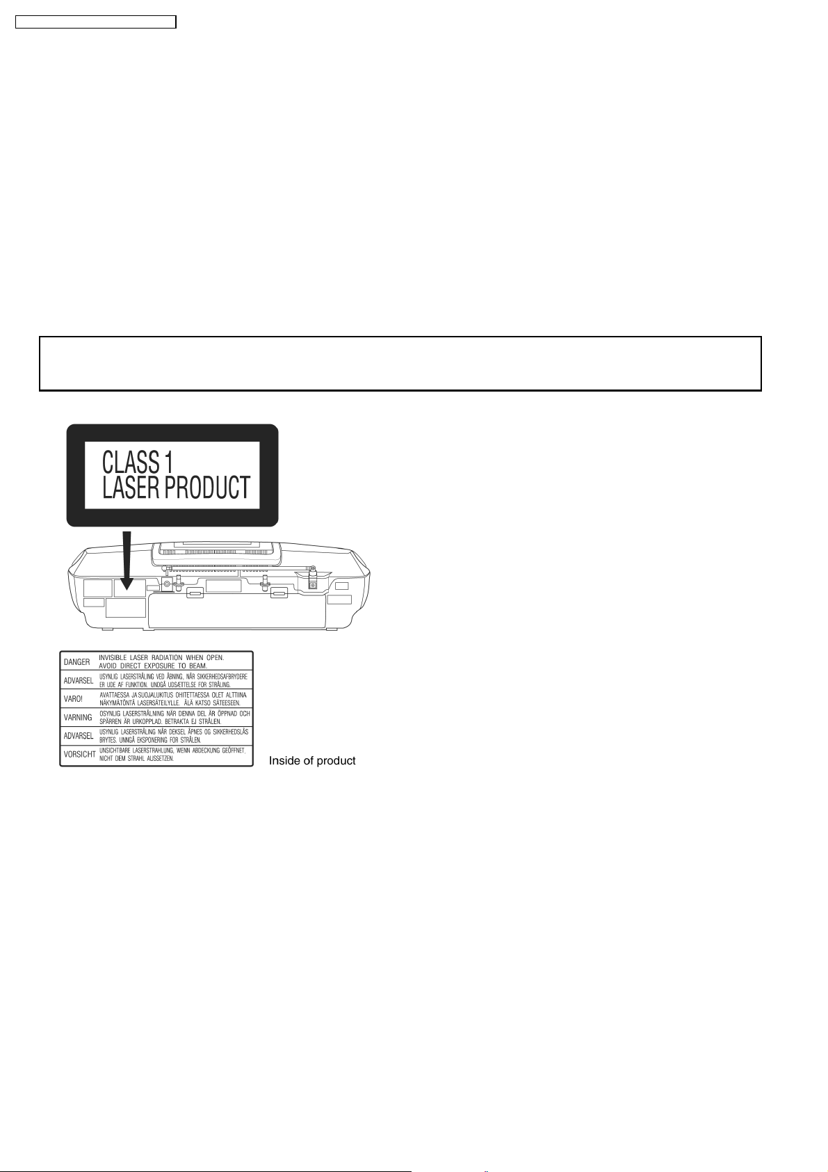
7 Precaution of Laser Diode
CAUTION:
This unit utilizes a class 1 laser.
Invisible laser radiation is emitted from the optical pickup lens.
When the unit is turned on:
1. Do not look directly into the pick up lens.
2. Do not use optical instruments to look at the pick up lens.
3. Do not adjust the preset variable resistor on the pickup lens.
4. Do not disassemble the optical pick up unit.
5. If the optical pick up is replaced, use the manufacturer’s specified replacement pick up only.
6. Use of control or adjustments or performance of procedures other than those specified herein may result in hazardous radiation
exposure.
CAUTION!
THIS PRODUCT UTILIZES A LASER.
USE OF CONTROLS OR ADJUSTMENTS OR PERFORMANCE OF PROCEDURES OTHER THAN THOSE SPECIFIED HEREIN MAY RESULT
IN HAZARDOUS RADIATION EXPOSURE.
6
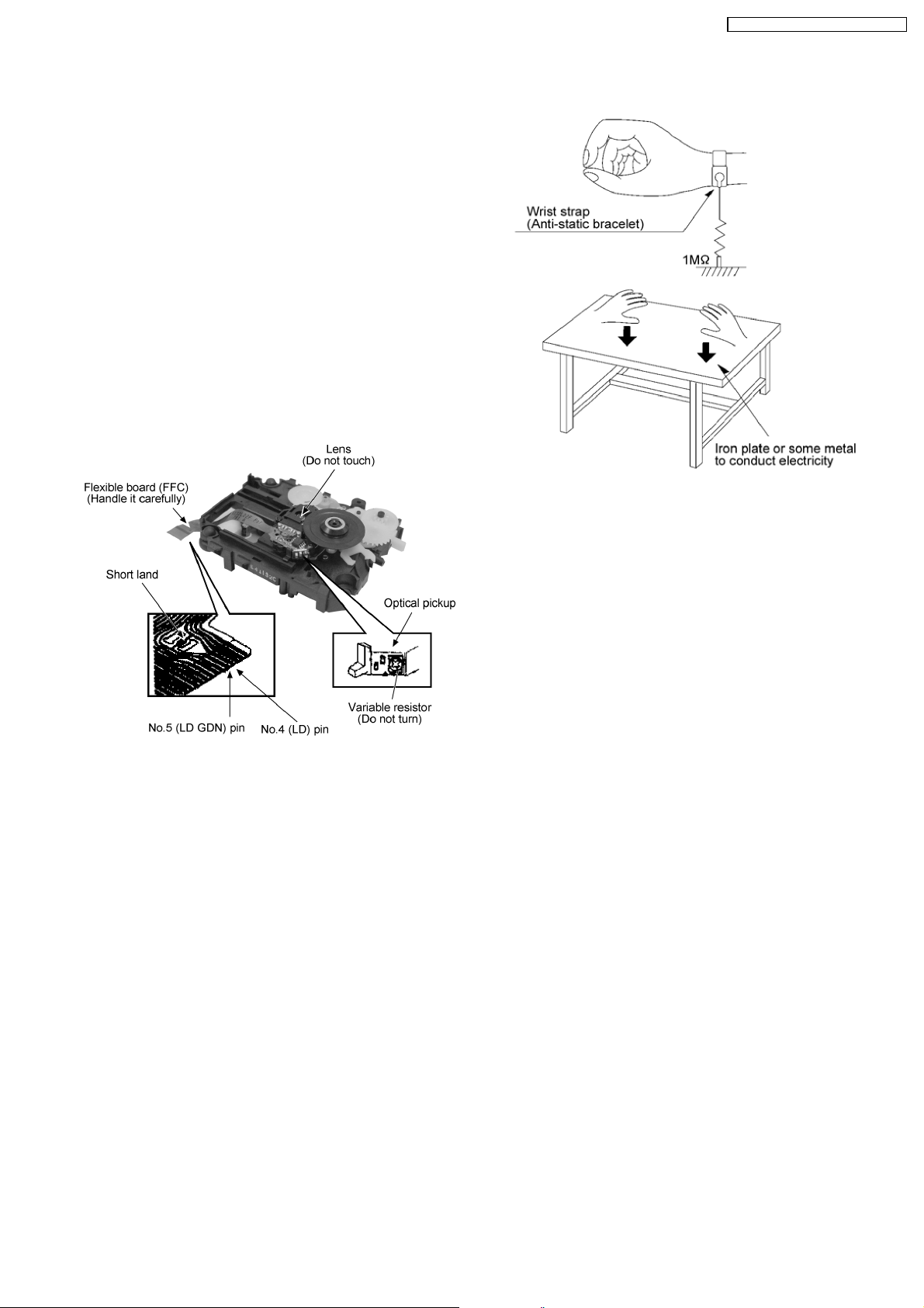
8 Handling Precautions For Traverse Deck
The laser diode in the traverse deck (optical pickup) may break
down due to potential difference caused by static electricity of
clothes or human body.
So, be careful of electrostatic breakdown during repair of the
traverse deck (optical pickup).
l Handling of CD traverse deck (optical pickup)
1. Do not subject the traverse deck (optical pickup) to
static electricity as it is extremely sensitive to electrical
shock.
2. The short land between the No.4 (LD) and No.5 (GND)
pins on the flexible board (FFC) is shorted with a solder
build-up to prevent damage to the laser diode.
3. Take care not to apply excessive stress to the flexible
board (FPC board) (Fig 8.1).
4. Do not turn the variable resistor (laser power
adjustment). It has already been adjusted.
RX-ES29GC / RX-ES29GS / RX- ES29GT
Fig 8.1
l Grounding for electrostatic breakdown prevention
1. Human body grounding (Fig 8.2)
Use the anti-static wrist strap to discharge the static
electricity from your body.
2. Work table grounding (Fig 8.2)
Put a conductive material (sheet) or steel sheet on the
area where the traverse deck (optical pickup) is placed,
and ground the sheet.
Caution :
The static electricity of your clothes will not be grounded
through the wrist strap. So, take care not to let your
clothes touch the traverse deck (optical pickup).
Fig 8.2
Caution when Replacing the Optical Pickup :
The traverse has a short point shorted with solder to protect
the laser diode against electrostatics breakdown. Be sure to
remove the solder from the short point before making
connections.
7
RX-ES29GC / RX-ES29GS / RX- ES29GT
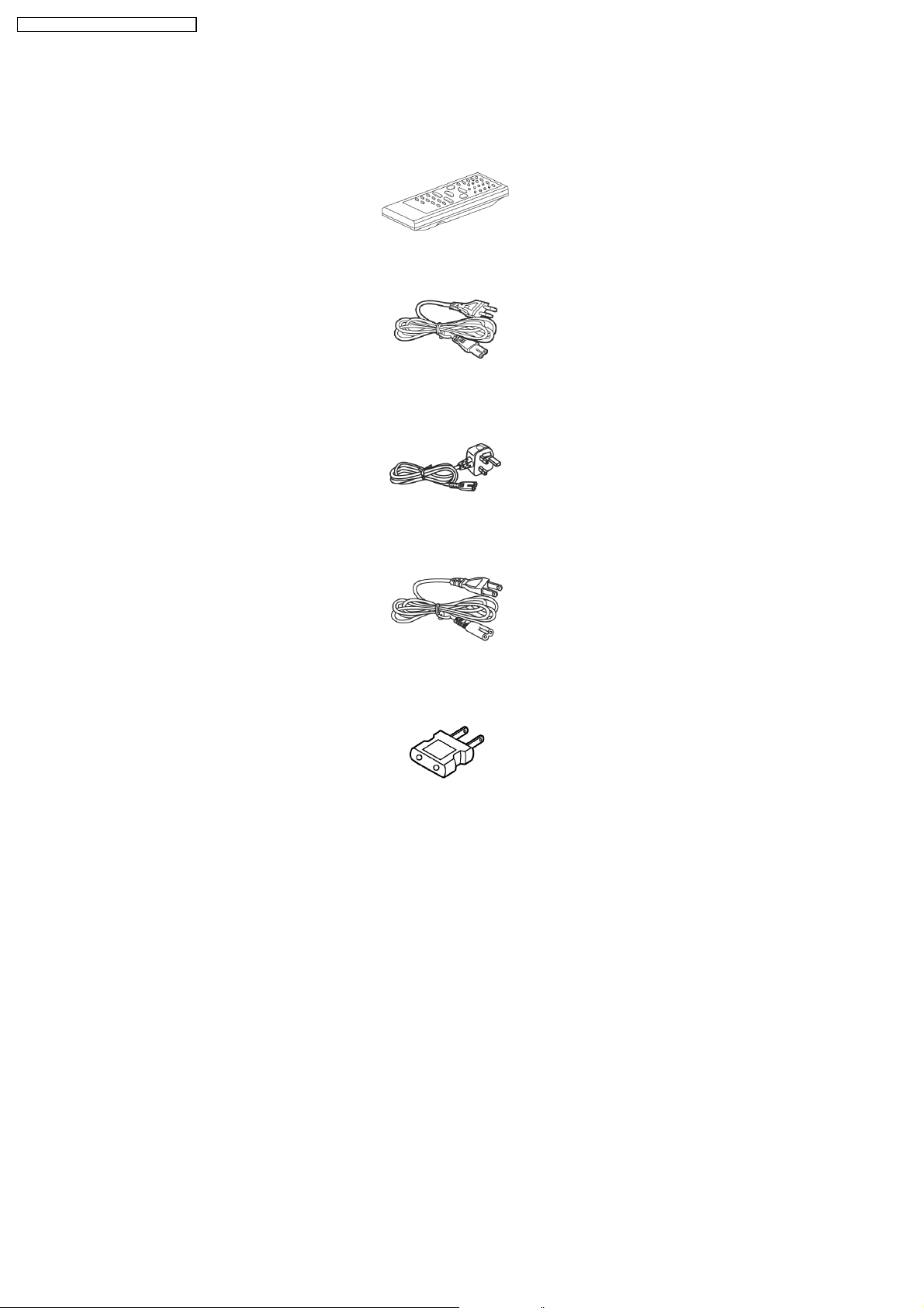
9 Accessories
Note : Refer to Packing Materials & Accessories Parts List (Section 25.5) for the part number.
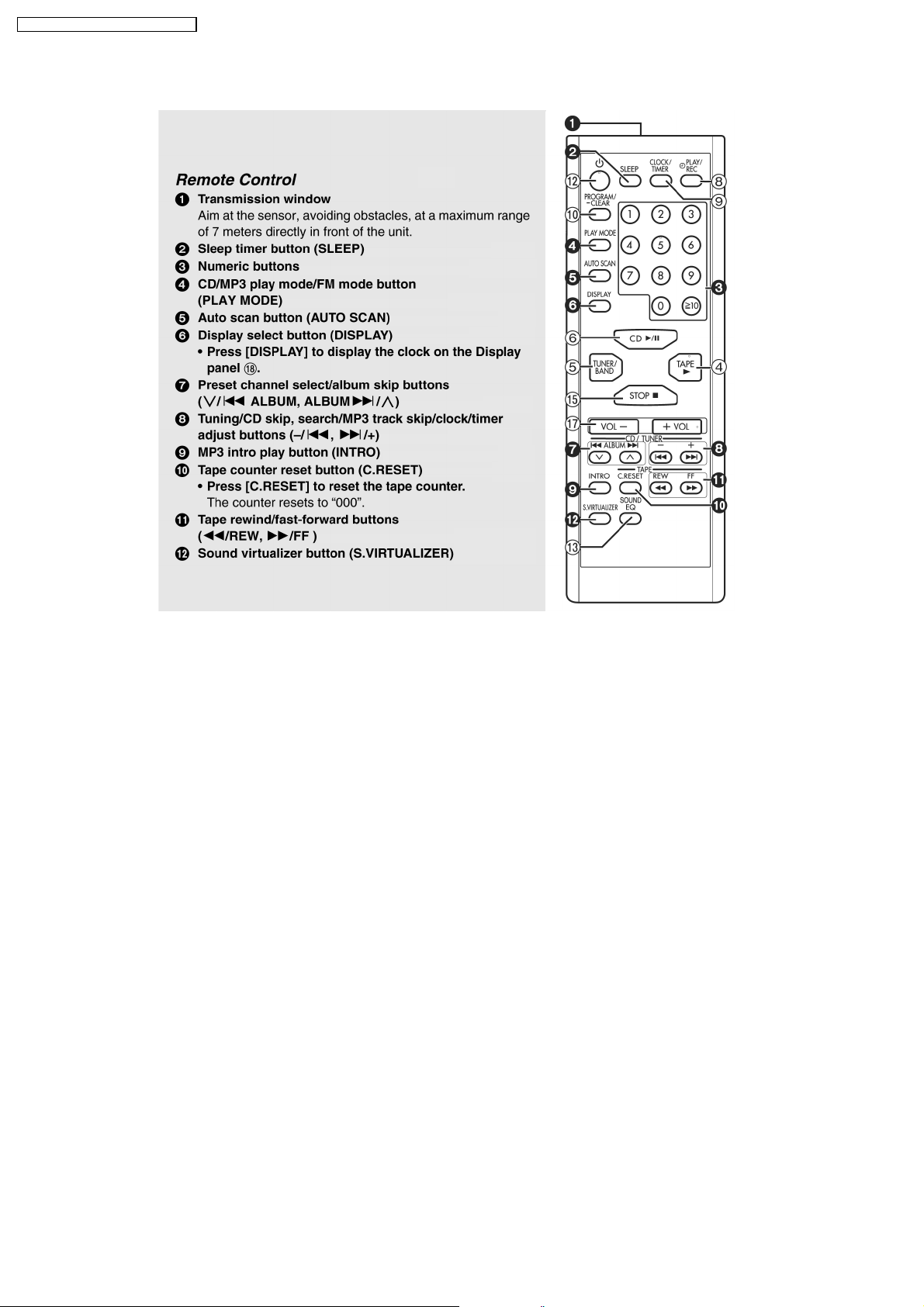
Remote Control.....1pc
AC cord.....1 pc (For
GC)
AC cord.....1 pc (For
GS)
AC cord.....1 pc (For
GT)
AC cord
adaptor.....1
pc (For GC)
8
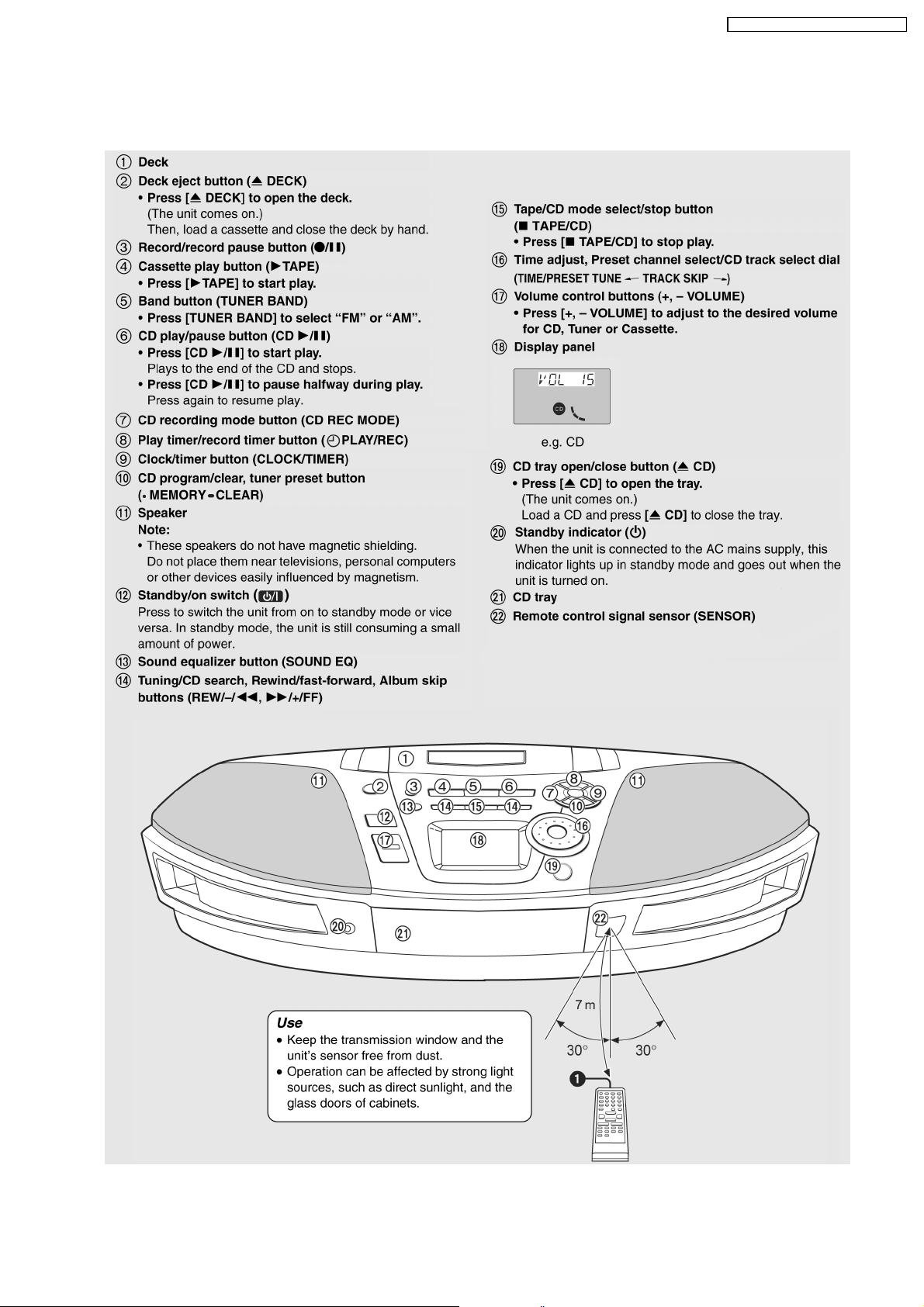
10 Operation Procedures
10.1. Main unit
RX-ES29GC / RX-ES29GS / RX- ES29GT
9
RX-ES29GC / RX-ES29GS / RX- ES29GT
10.2. Remote control
10
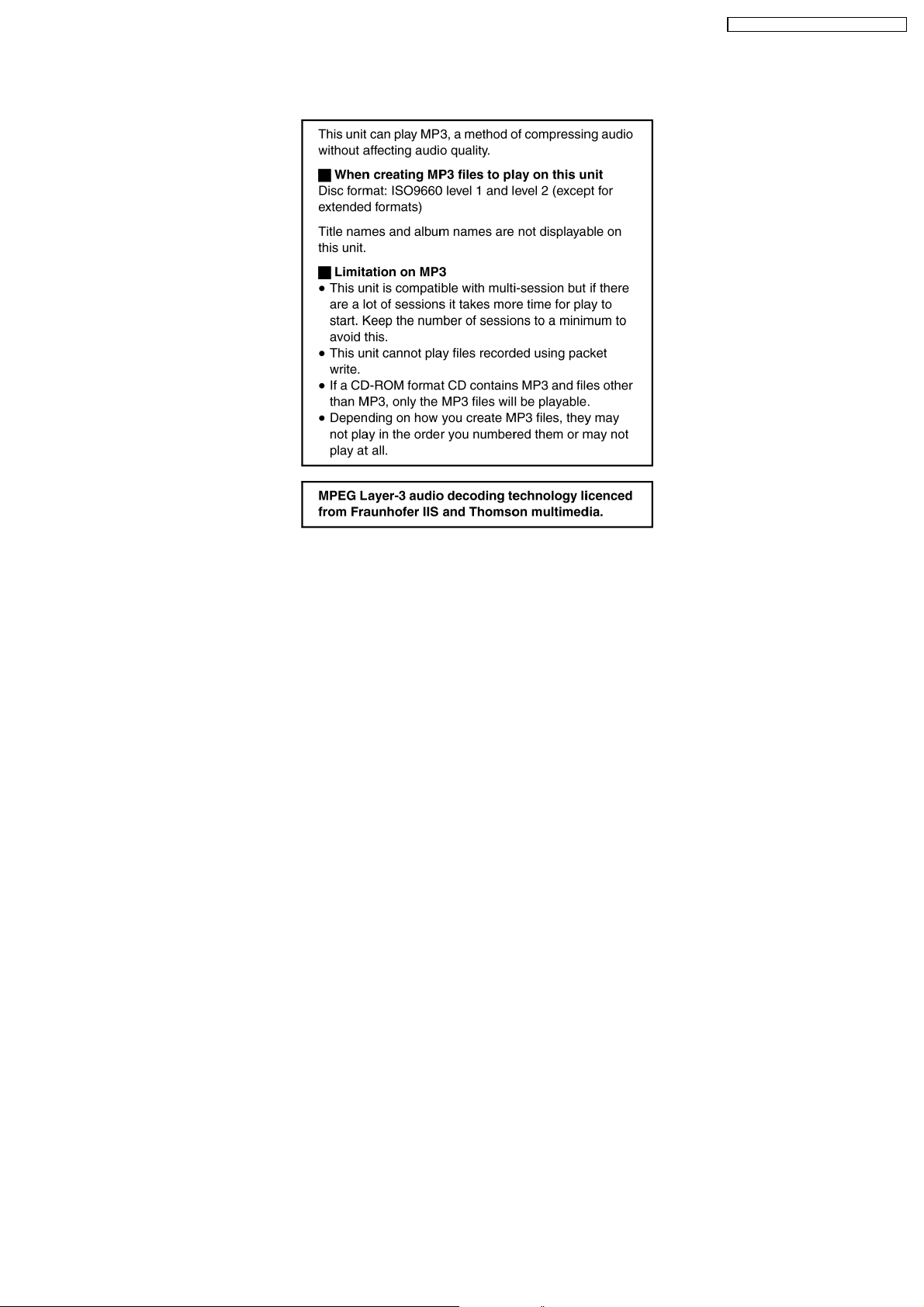
11 Information on MP3
RX-ES29GC / RX-ES29GS / RX- ES29GT
11
RX-ES29GC / RX-ES29GS / RX- ES29GT
12 Disassembly and Main Component Replacement
Procedures and Operational Check
“ATTENTION SERVICER”
Some chassis components may be have sharp edges. Be careful when disassembly and servicing.
1. This section describes procedures for checking the operation of the major printed circuit boards and replacing the main
components.
2. For reassembly after operation checks or replacement, reverse the respective procedures.
Special reassembly procedures are described only when required.
3. Select items from the following index when checks or replacement are required.
Warning:
This product uses a laser diode. Refer to “Precaution of Laser Diode”.
12.1. Disassembly procedures
12.3. Checking Procedure for each major P.C.B.
12.3.1 Disassembly of Top Cabinet Unit.
12.3.2 Disassembly of Panel P.C.B.
12.3.3 Disassembly of Speakers.
12.3.4 Disassembly of Deck Mechanism.
12.3.5 Disassembly of Main, Standby LED, Power On and Sensor P.C.B.
12.3.6 Disassembly of Battery and Power P.C.B.
12.3.7 Disassembly of CD Loading Mechanism.
12.3.8 Replacement of Cassette Panel.
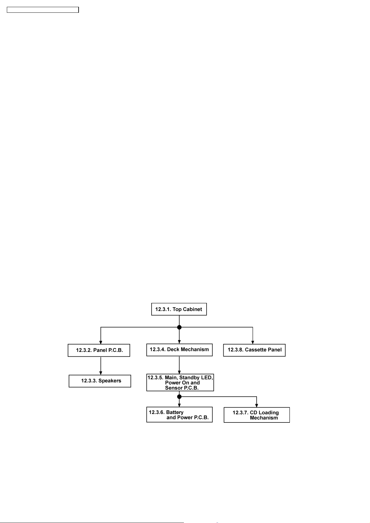
12.2. Disassembly flow chart
The following chart is the procedure for disassembling the unit and inside parts for internal inspection when carrying out the
servicing.
To assemble the unit, reverse the steps shown in the chart below.
12
12.3. Checking Procedure for each major P.C.B.
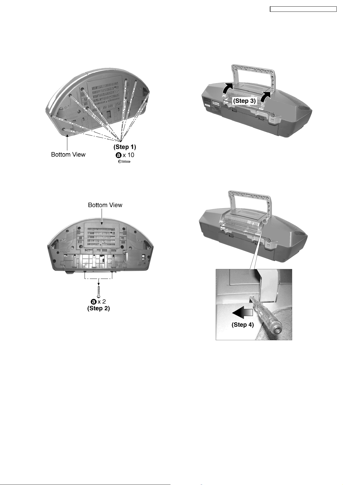
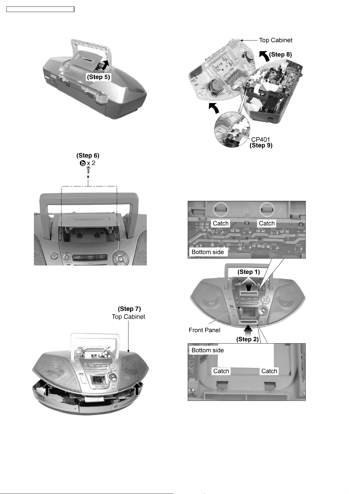
12.3.1. Disassembly of Top Cabinet Unit.
Step 3: Flip up the handle as arrow direction shown.
RX-ES29GC / RX-ES29GS / RX- ES29GT
Step 1: Remove 10 screws.
Step 2: Remove 2 screws.
Step 4: Use a screw driver and insert into the hole. Slide the
screw driver to the direction shown to open the cassette panel.
Note: Be careful not to exert strong force as it may cause
damage to the chassis.
13
RX-ES29GC / RX-ES29GS / RX- ES29GT
Step 5: Cassette panel will automatically open.
Step 8: Flip the top cabinet over as arrow shown.
Step 9: Detach the FFC wire (CP401).
Step 6: Remove 2 screws.
12.3.2. Disassembly of Panel P.C.B.
Follow (step 1) to (step 9) of item 12.3.1.
Step 7: Lift up the top cabinet as arrow shown.
Step 1: Lift the upper section of the front panel slightly towards
you as arrow shown.
Step 2: While lifting, push the lower section of the front panel
in the direction shown by the arrow to release the catches.
14
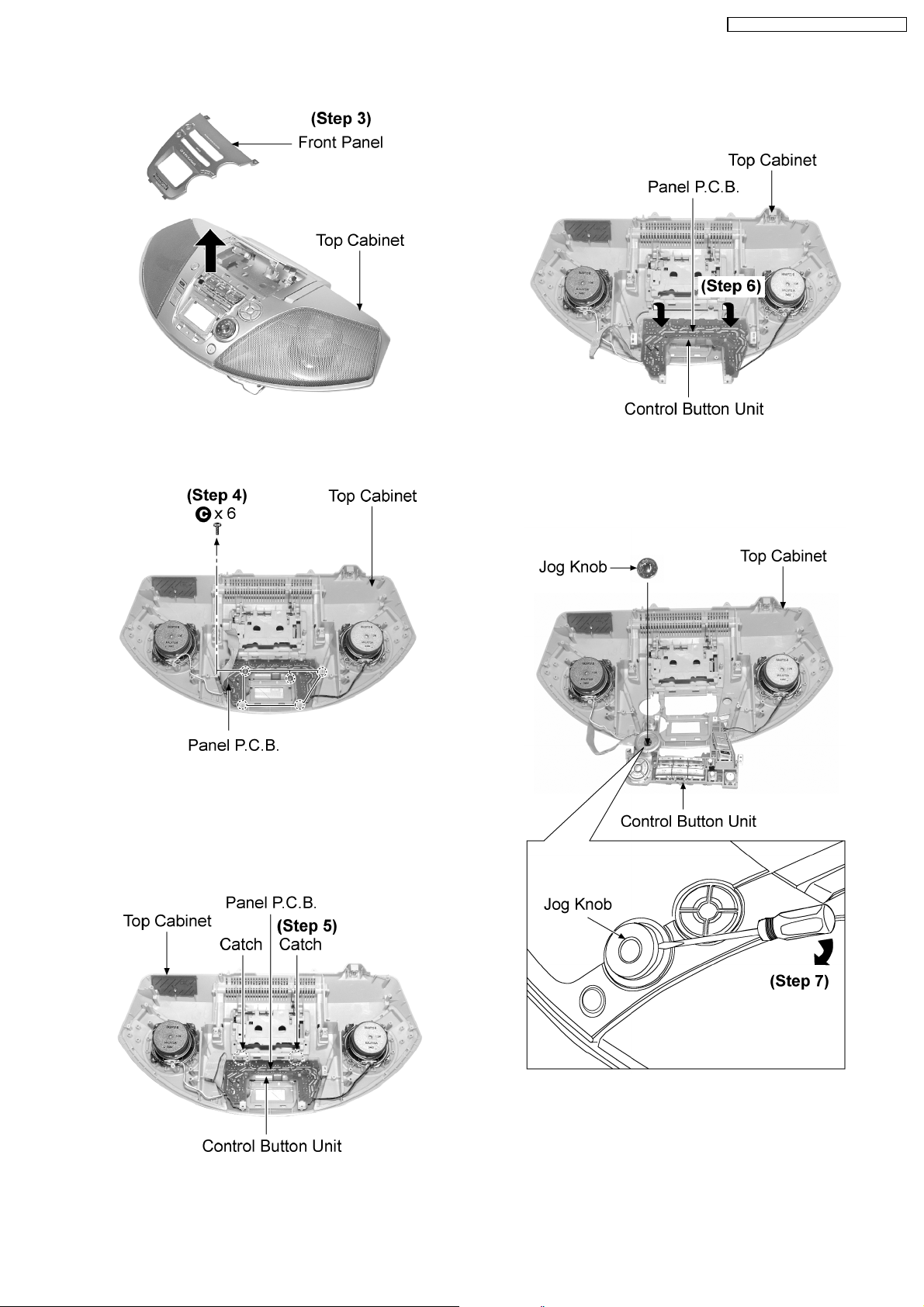
Step 3: Remove the front panel from top cabinet as arrow
shown.
RX-ES29GC / RX-ES29GS / RX- ES29GT
Step 5: Release 2 catches.
Step 6: Flip over the control button unit with the Panel P.C.B.
as arrow shown.
Step 4: Remove 6 screws.
Step 7: Remove the Jog Knob using a screwdriver as arrow
shown.
Caution: Do not exert strong force as it may cause damage to
the top cabinet.
15
RX-ES29GC / RX-ES29GS / RX- ES29GT
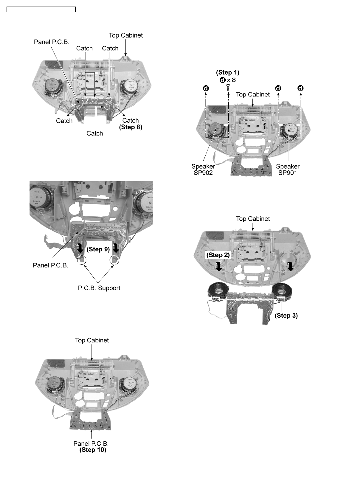
Step 8: Release 6 catches.
12.3.3. Disassembly of Speakers.
Follow (step 1) to (step 9) of item 12.3.1.
Follow (step 1) to (step 10) of item 12.3.2.
Step 9: Remove the Panel P.C.B. as arrow shown.
Step 1: Remove 8 screws.
Step 2: Flip the both side speakers as arrow shown.
Step 3: Desolder the wire at speaker terminal to remove
speaker.
Step 10: Flip the Panel P.C.B. over.
12.3.4. Disassembly of Deck Mechanism.
Follow (step 1) to (step 9) of item 12.3.1.
16
RX-ES29GC / RX-ES29GS / RX- ES29GT
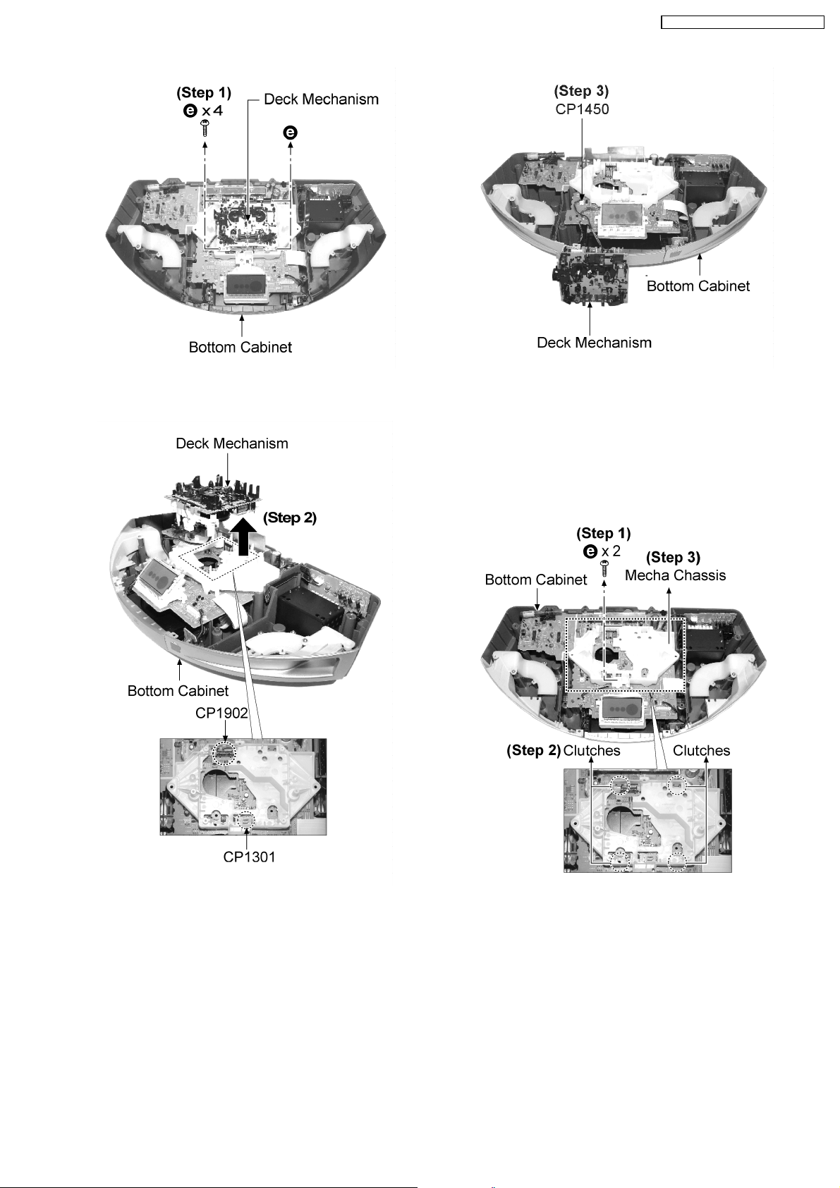
Step 1: Remove 4 screws.
Step 3: Release the connector (CP1450) to remove the deck
mechanism.
12.3.5. Disassembly of Main, Standby
LED, Power On and Sensor P.C.B.
Follow (step 1) to (step 9) of item 12.3.1.
Follow (step 1) to (step 3) of item 12.3.4.
Note: Be careful of connectors (CP1301 & CP1902) while
removing the deck mechanism.
Step 2: Remove the deck mechanism as arrow shown.
Step 1: Remove 2 screws.
Step 2: Release 4 clutches.
Step 3: Remove the Mecha Chassis.
17
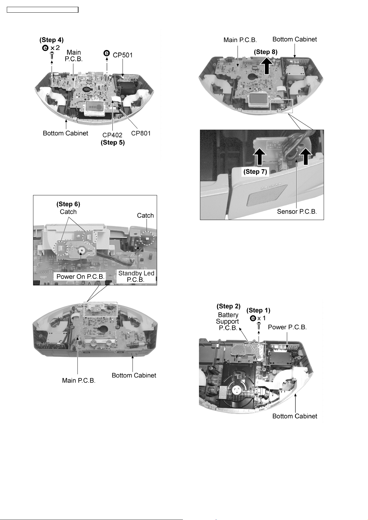
RX-ES29GC / RX-ES29GS / RX- ES29GT
Step 4: Remove 2 screws.
Step 5: Release all the connectors (CP501, CP402 & CP801).
Step 6: Release 3 Catches and remove Power On P.C.B. and
standby Led P.C.B..
Step 7: Release the Sensor P.C.B. as arrow shown.
Step 8: Remove the Main P.C.B. as arrow shown.
12.3.6. Disassembly of Battery and Power
P.C.B.
Follow (step 1) to (step 9) of item 12.3.1.
Follow (step 1) to (step 3) of item 12.3.4.
Follow (step 1) to (step 8) of item 12.3.5.
Step 1: Remove 1 screw.
Step 2: Remove the Battery Support P.C.B..
Note: Remember to place the Battery Support P.C.B. to
original location.
18
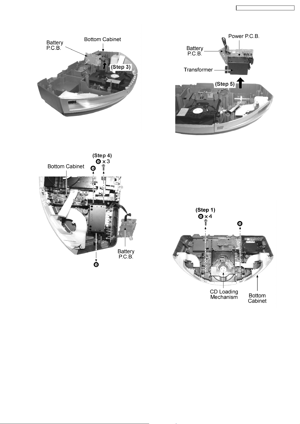
Step 3: Remove the Battery P.C.B. as arrow shown.
RX-ES29GC / RX-ES29GS / RX- ES29GT
Step 5: Remove the transformer together with battery P.C.B.
and Power P.C.B. as arrow shown.
Step 4: Remove 3 screws.
12.3.7. Disassembly of CD Loading
Mechanism.
Follow (step 1) to (step 9) of item 12.3.1.
Follow (step 1) to (step 3) of item 12.3.4.
Follow (step 1) to (step 8) of item 12.3.5.
Step 1: Remove 4 screws.
19
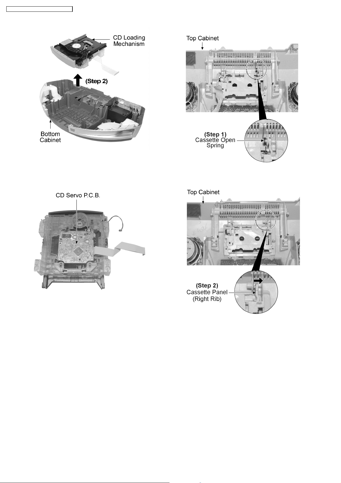
RX-ES29GC / RX-ES29GS / RX- ES29GT
Step 2: Remove the CD Loading Mechanism as arrow shown.
Step 1: Remove the cassette open spring.
12.3.8. Replacement of Cassette Panel.
Follow (step 1) to (step 9) of item 12.3.1.
Step 2: Push the cassette panel slowly to the right.
20
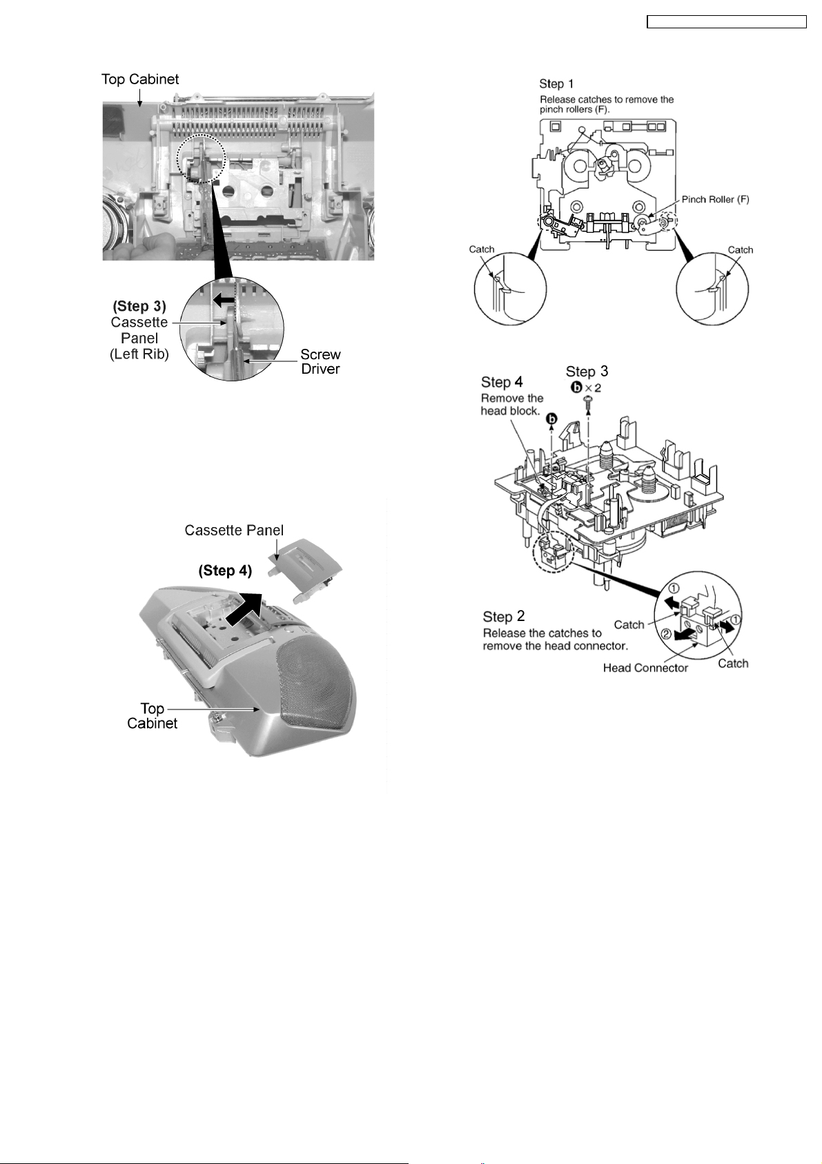
RX-ES29GC / RX-ES29GS / RX- ES29GT
Step 3: Push the cassette panel slowly to the left using a screw
driver.
Caution: Be careful of using/exerting strong forces.
Step 4: Remove the cassette panel from top cabinet as arrow
shown.
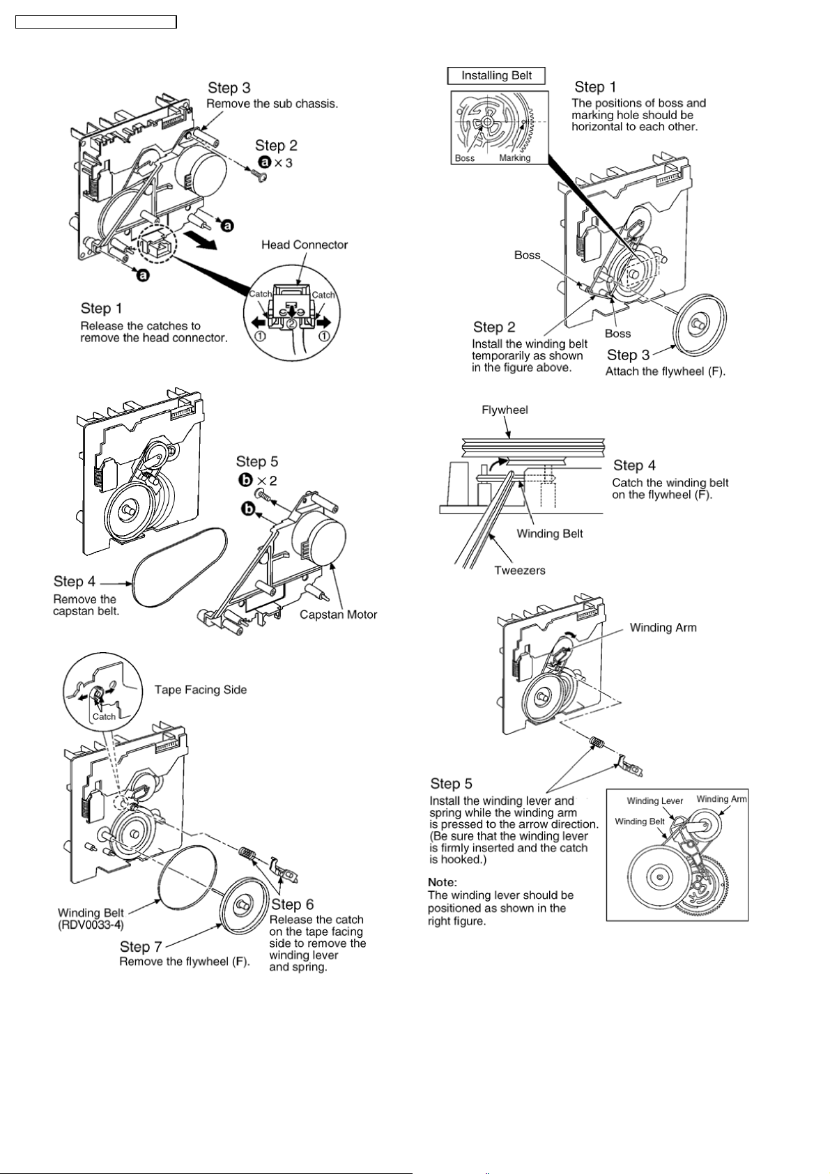
12.4. Procedures for Replacing
Pinch Roller and Head Block
(Deck Mechanism Unit)
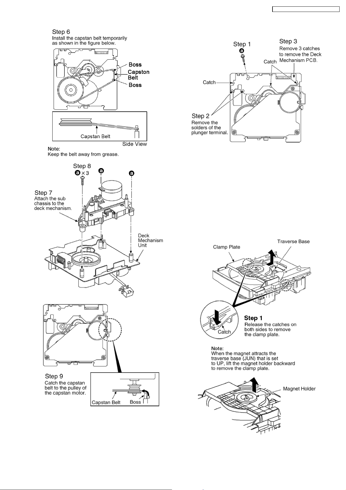
12.5. Procedures for Replacing
Motor, Capstan Belt A,
Capstan Belt B, and Winding
Belt (Deck Mechanism Unit)
Follow (step 1) to (step 9) of item 12.3.1.
Follow (step 1) to (step 3) of item 12.3.4.
Follow (step 1) to (step 9) of item 12.3.1.
Follow (step 1) to (step 3) of item 12.3.4.
21
RX-ES29GC / RX-ES29GS / RX- ES29GT
22
RX-ES29GC / RX-ES29GS / RX- ES29GT
Follow (step 1) to (step 3) of item 12.3.4.
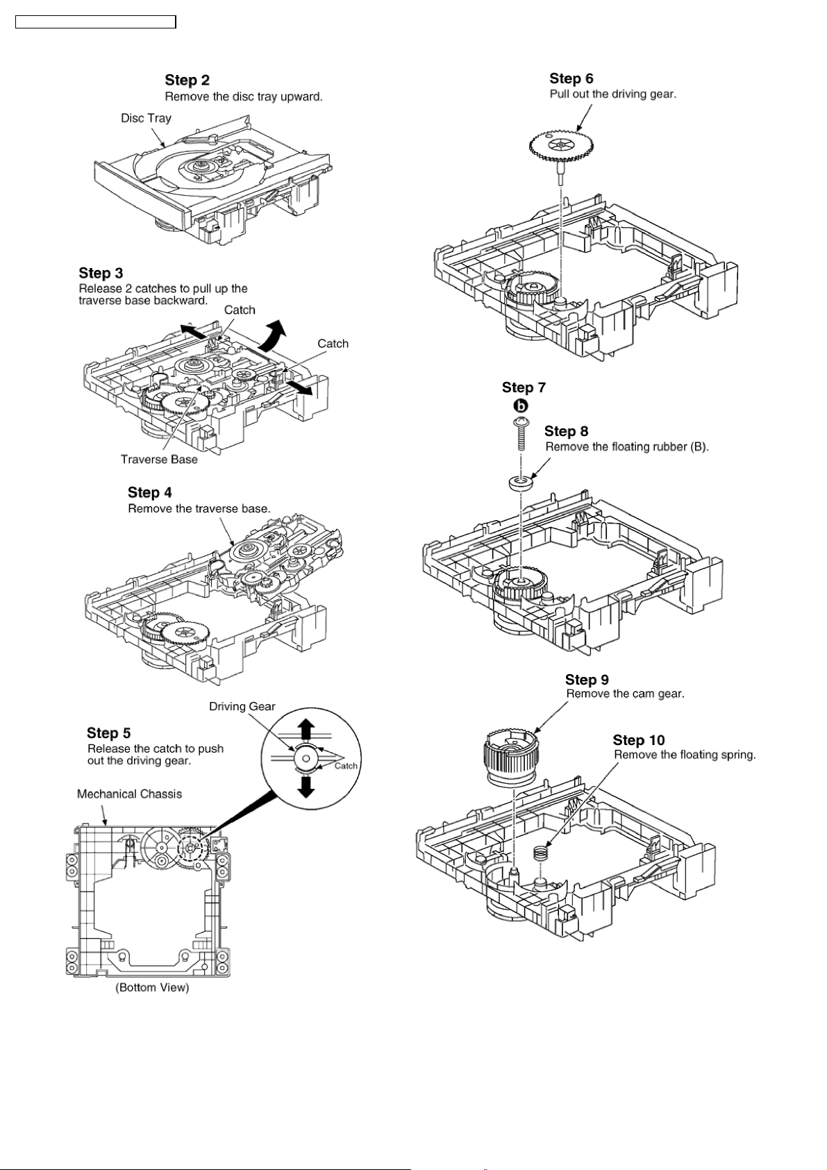
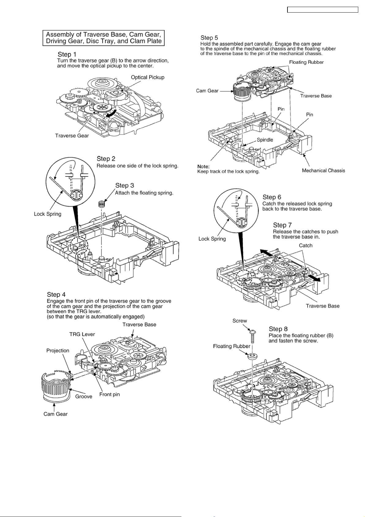
12.7. Procedures of Replacing
Traverse Base (Unit), Driving
Gear, and Cam Gear (CD
Mechanism Unit)
12.7.1. Disassembly of the Disc Tray.
Follow (step 1) to (step 9) of item 12.3.1.
Follow (step 1) to (step 3) of item 12.3.4.
Follow (step 1) to (step 8) of item 12.3.5.
Follow (step 1) to (step 2) of item 12.3.7.
12.6. Procedures for Replacing
Parts on Deck Mechanism
PCB
Follow (step 1) to (step 9) of item 12.3.1.
23
RX-ES29GC / RX-ES29GS / RX- ES29GT
24
RX-ES29GC / RX-ES29GS / RX- ES29GT
25
RX-ES29GC / RX-ES29GS / RX- ES29GT
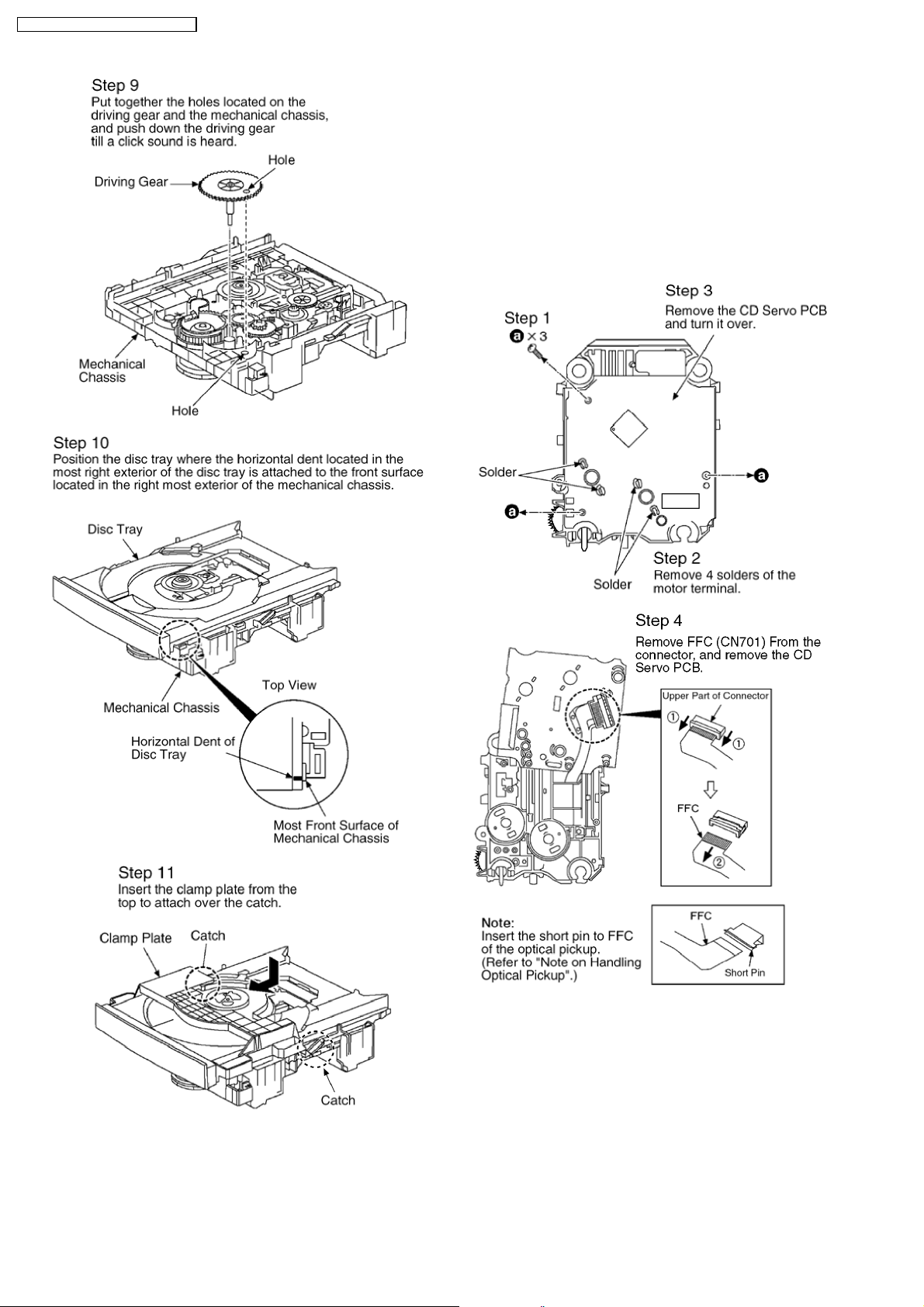
12.8. Procedures for Replacing
Optical Pickup (CD Mechanism
Unit)
Follow (step 1) to (step 9) of item 12.3.1.
Follow (step 1) to (step 3) of item 12.3.4.
Follow (step 1) to (step 8) of item 12.3.5.
Follow (step 1) to (step 2) of item 12.3.7.
Follow (step 1) to (step 4) of item 12.6.1.
26
 Loading...