

Panasonic RXDT-30 Service manual
ORDER NO. MD9502012C1
Service
Manual
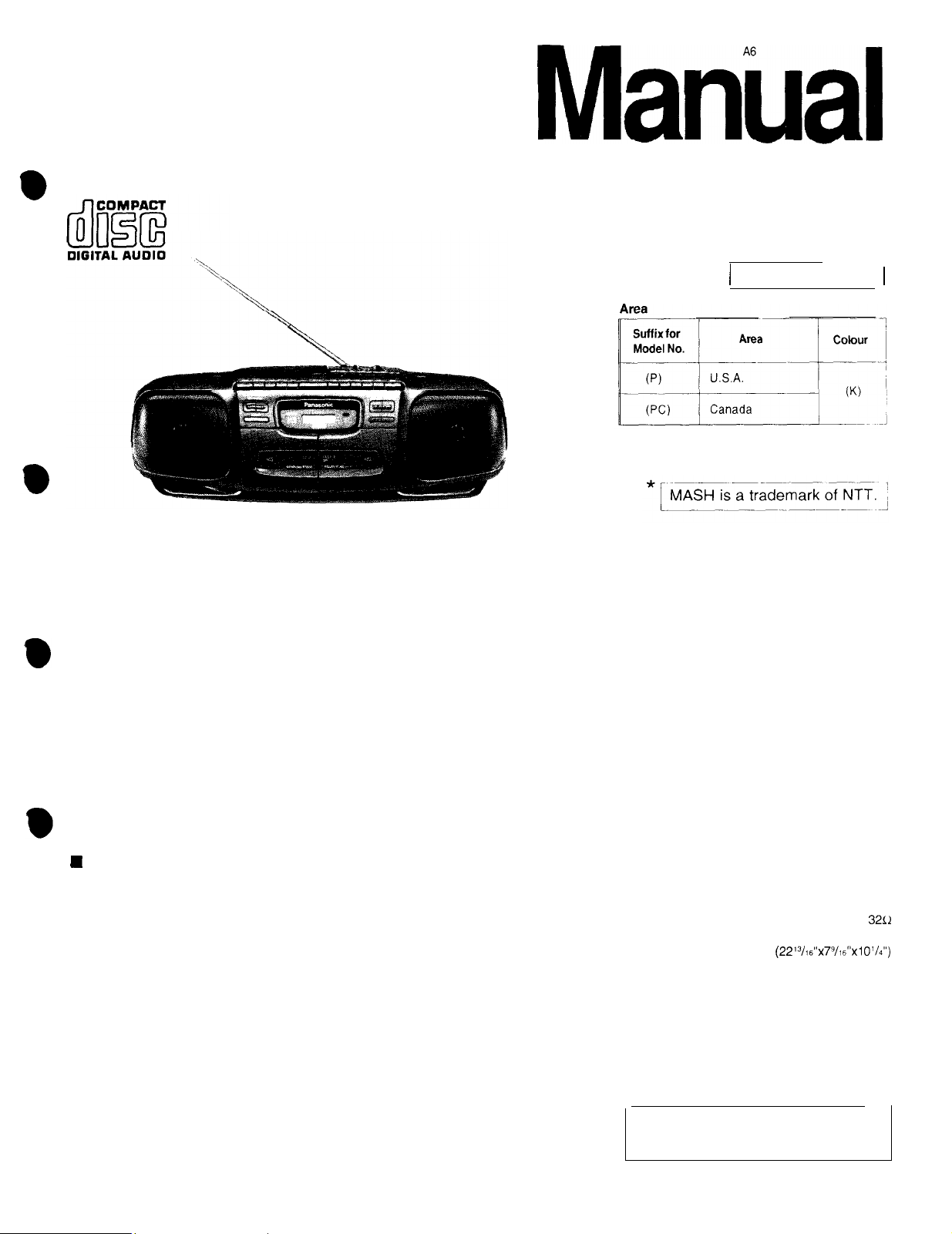
Portable Stereo CD System
MASH*
TAPE DECK
TRAVERSE DECK : RAE01 13Z MECHANISM SERIES
: SG-20W MECHANISM SERIES
Radio Cassette
RX-DT30
Colour
/
(K) Black Type 1
I
SPECIFICATIONS
n
Radio Section
Frequency range
FM
AM
Intermediate frequency
FM
AM
Sensitivity
FM
AM
H CD Player
Sampling frequency
Decoding
Beam source
No. of channels
Wow and flutter
D/A
converter
88-108MHz
525 - 1705
17
(
-3 dB limit sens.
51
dB/m/50
Semiconductor laser
(wavelength 780 nm)
2 channel, stereo
Less than possible measurement data
MASH (1 bit DAC)
kHz
10.7 MHz
455
kHz
dB/50 mW
mW
44.1
kHz
16 bit
Iinear
n
Tape Recorder
Track system
Recording system
Erasing system
Monitor system
Frequency range
Normal
)
n
General
Power requirement
AC
Battery
Speakers
Jacks
Output
Dimensions (W x H x D)
Weight
Notes
:
Specifications are subject to change without notice.
Weight
and
dimensions are approximate.
12 V (8
4.5 kg (9 lb.
4 track, 2 channel, stereo
Multi
Variablesoundmonitor
Power consumption; 30W
“D”
size, R20/LR20 batteries)
15 oz.)
pole magnet
50
-
14000 Hz
120V, 60Hz
10 cm (4”) x 2
Headphones;
580x192
(22’3/~s”x79/~6”x1 01/4”)
x260mm
without batteries
AC bias
32c1
Panasonic”
©
1995 Matsushita Electronics (S) Pte. Ltd.
All rights reserved. Unauthorized copying and
distribution is a violation of law.
RX-DT30
n
Disassembly Instructions
Warning :
ACHTUNG :
“ATTENTION SERVICER”
Ref. No.
This
1
product uses a laser
Die
laserernheit
Die
lasereinheit darf nur gegen eine vom hersteller
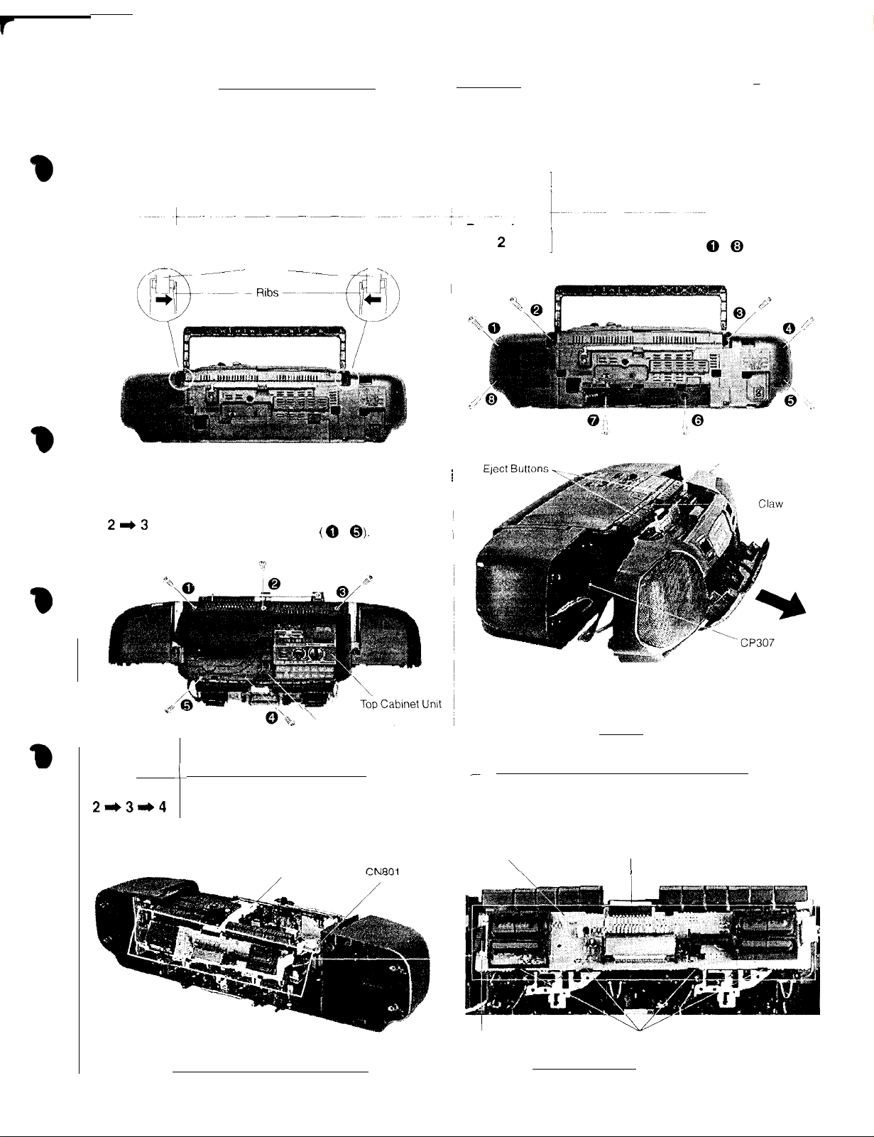
Removal of the Handle
Procedure
1
_
-m--_--
Ref. No.
3
Removal of the Top Cabinet Unit
Procedure
2*3
diode.
zerlegen.
-__
Refer to
(0
-
nicht
Some chassis components may have sharp edges. Be careful when
1.
Release 2 ribs.
2.
Pull out the handle.
Handle
1.
Press the CD eject button.
2. Remove 5 screw
3. Remove the Top Cabinet
caution
statements on page 2.
Q).
Unit.
spezrfizierte
Ref. No.
Procedure
~
einheit ausgetauscht werden.
disassembling
I
Removal of the Front Cabinet
2
:
1.
Remove the battery cover.
2. Remove 8 screws
1
and servicing.
( @ - 0 ).
_,
Front Cabinet
Ref. No.
4
Procedure
2+31,4
\
CD Eject Button
Removal of the Control P.C.B.
1
1. Remove 2 connectors (CN303, CN801).
2. Remove FFC cable from the connector CN702 (Control P.C.B.).
3. Release 4 claws.
FFC Cable
3.
Press the 2 eject buttons.
4.
Release 1 claw.
5. Remove the front cabinet in the
6.
Remove 1 connector
Control P.C.B.
CN303
(CP307).
CN702
I
Claws
direction
of arrow
-5-
RX-DT30
I
Ref. No.
5
Procedure
2*31,5
1..
Remove
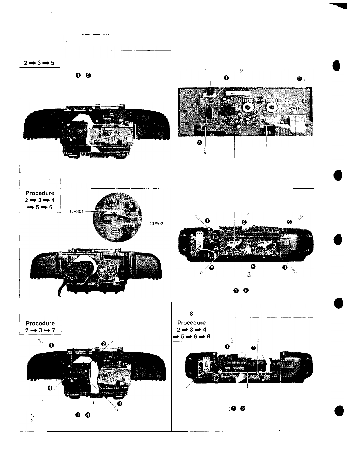
2. Remove 4 connectors
3. Remove the Connector P.C.B.
3
r- ~
---~~~
-~~~
Removal of the Connector P.C.B.
screws
(0-Q).
(CN1,
-~~~~
CN304. CN305,
CN801).
CN1
CN305
Ref. No.
6
Ref. No.
7
~----I
Removal of the Mechanism Unit
_.~ ~~~
Removal of the Traverse Unit
.~~~~~
;<
R
1.
Remove 2 connectors
2. Remove 6 screws
Ref. No.
Connector P.C.B.
I
Mechanism Unit
(CP301, CP602
( @ - @ ).
CN304
)
Removal of the Main P.C.B.
CN801
FFC Cable
Traverse Unit
*
Remove 4 screws
Remove FFC cable from the connector CN702 (Control P.C.B.)
( 0 - 0 ).
I
CN702
-6-
CP306
1..
Remove 2 screws
2.
Remove 1 connector
out the main P.C.B. in the direction of arrow.
Pull
3.
Main P.C.B.
(8
-@
(CP306).
).

RX-DT30
Power
SUPPLY
P.C.B.
i
CP306 -m$j
Ref. No. ~
?
11
Procedure
2*3*11
Removal of the Power Supply
1.
Remove 6 screws
2. Remove 1 connector
I
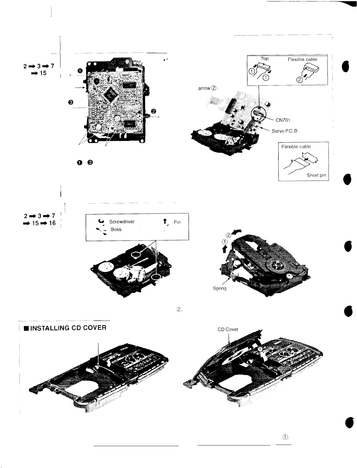
Removal of the CD Cover
(
/
(0
(CP306)
- @
P.C.B.
).
Ref. No.
10
Procedure
21,9*10
Ref. No.
12
-7
;
Removal of the Battery
-I.-
1.
Release 1 claw.
I
2. Pull out the battery P.C.B.
P.C.B.
Removal of the Disc Clamp Unit
Procedure
21,31,12
CD Cover
1.
Hold the CD cover in half-open
2. Release the rib in direction of arrow
3. Pull out the CD cover in direction of
4. Release the
5. Pull out the CD cover.
Ref. No.
13
Procedure
2413
,?,
Speaker
rib
in
direction
)
i
Removal of the Speakers
I
~~~~
~~~ -~~
1
1
1. Remove 8 screws
2. Cut black bond at wire
before removal of the speakers.
$”
of
position.
arrow@
~~
e;l.
arrow3.
~~~~ -~ ~ -~~
( 0
- @
).
dressing point
‘2;
Speaker
Bond
1.
Press the CD eject button and then open the CD cover.
2. Remove the
Ref. No.
14
disc
clamp
unit in
the direction of arrow
’
I
Removal of the Cassette Compartment
(Ijfollow by(2,‘
RX-DT30
1
Ref. No.
15
1
Removal of the Servo P.C.B.
~~~ I
Procedure
21,31,7
*15
,
;
Traverse
Terminals
1.
Remove 3 screws
2. Desolder 2 termrnals of
3. Desolder 2 termrnals of traverse motor.
4. Remove the flexrble cable from
Ref. No.
Procedure
21)31)7
*151,16
Unit -
of traverse motor
( 0
’
116Removal of the Traverse Deck Ass’y
Terminals of spindle motor
- 0
).
spindle
1
’
:
~~,
motor.
CN701
Removal of the flexrble cable
Push the top of the connector in the
direction
pull out the flexrble cable
directron of the
P
of the arrow@, and then
arrowa.
Note
:
Insert a short
traverse unit.
pin into
in
the
the flexible cable for
Traverse Deck Ass’y
1.
Widen
2.
1.
2 bosses by
Remove the Traverse Deck Ass’y in direction of arrow @follow by
Install the CD open spring as shown in above diagram.
using
a flat tip screwdriver and remove 2 pins.
CD OpenSpring
-8-
;2,.
Install the CD cover onto the top
2.
Note
:
When
IS in half open positron.
Release the
3.
spring
installing
the CD cover, make sure the CD cover
in the directton of arrow
cabinet.
0.
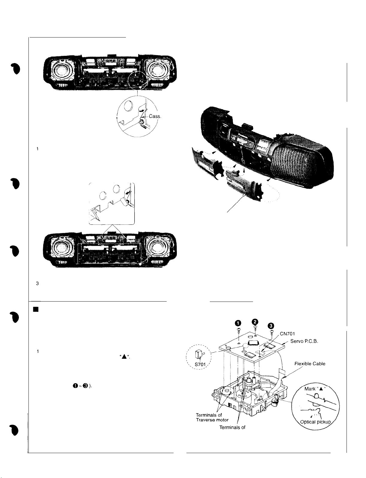
n
INSTALLING CASSETTE COMPARTMENT
I
J /J-Cass.
,
Open
RX-DT30
Spring
Install the
Release the spring
cass.
open
spring
as shown in above diagram.
INSTALLING SERVO P.C.B.
Cassette Compartment
2. Fix the cassette compartment to front cabinet
Before installing the servo P.C.B., move the optical pickup
toward the outer edge from the mark
(Otherwise, the rest switch
P.C.B may be damaged.)
2. Connect the flexible cable to the connector (CN701).
3. Install the servo P.C.B. in the traverse deck ass’y with
the 3 screws
4. Solder the 2 terminals of the traverse motor and the
2 terminals of the spindle motor.
Note
:
( 0 - @I ).
Connect the flexible cable to the connector (CN701)
firmly.
Tighten the screws before soldering the terminals.
(S701)
“A”.
mounted on the servo
Spindle motor
__
-9-
RX-DT30
n
I
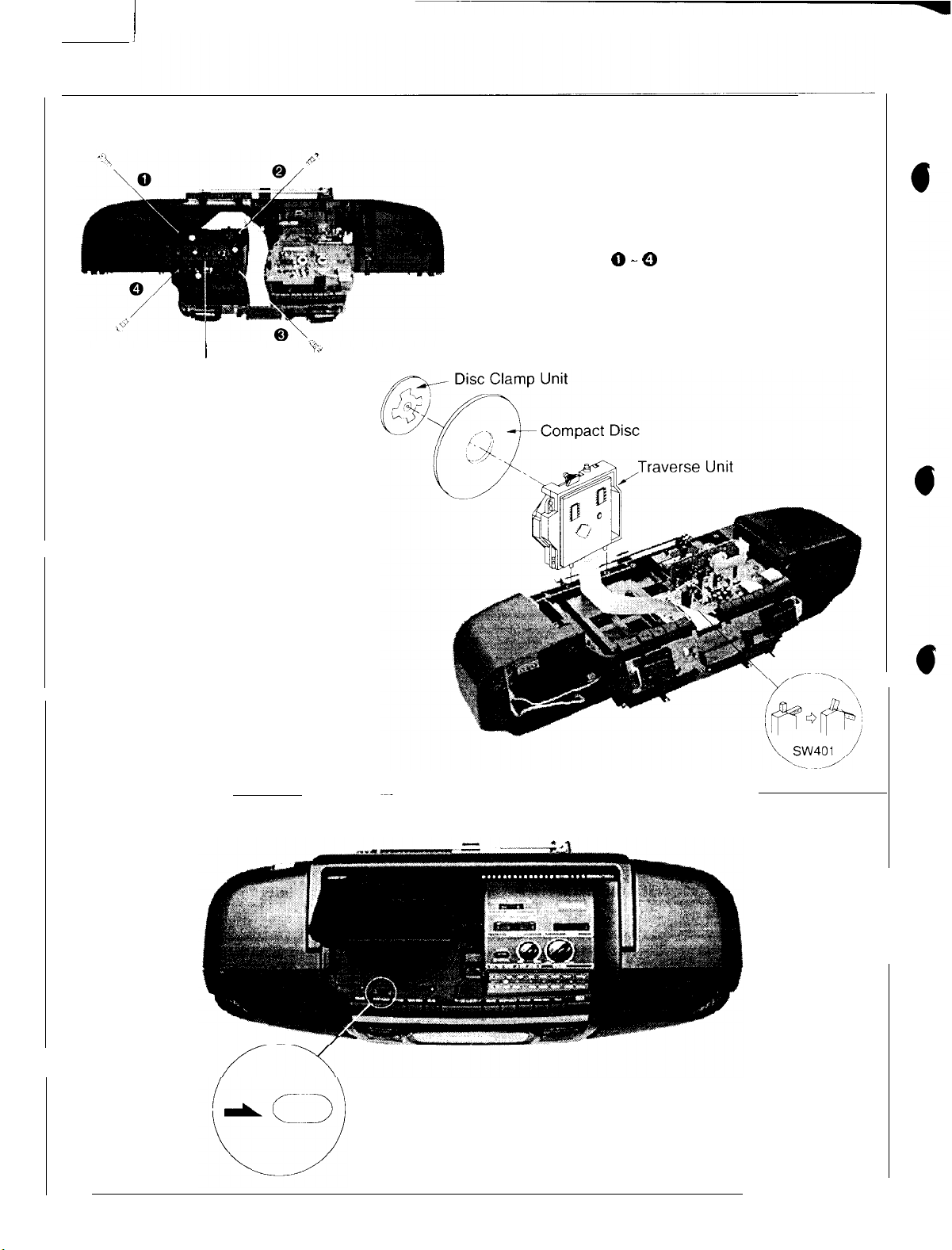
HOW TO CHECK THE TRAVERSE UNIT
I
Traverse Unit
3. Set up the traverse unit as shown in diagram.
4. Install the compact disc and disc clamp unit.
Note
:
Before perform checking, make sure the
switch SW401 is switched to “ON” position.
(as shown
in
diagram).
1. Remove the top cabinet
(Refer to disassembly instructions, Fief No. 3)
2.
Remove4screws.
unit.
(0-0)
n WHAT TO DO WHEN THE TAPE IS ENTANGLED
When the tape is caught in the pitch roller, etc. Release the tape
by turning the pulley on the motor with the screwdriver in the
direction of arrow.
-lO-
/
RX-DT30
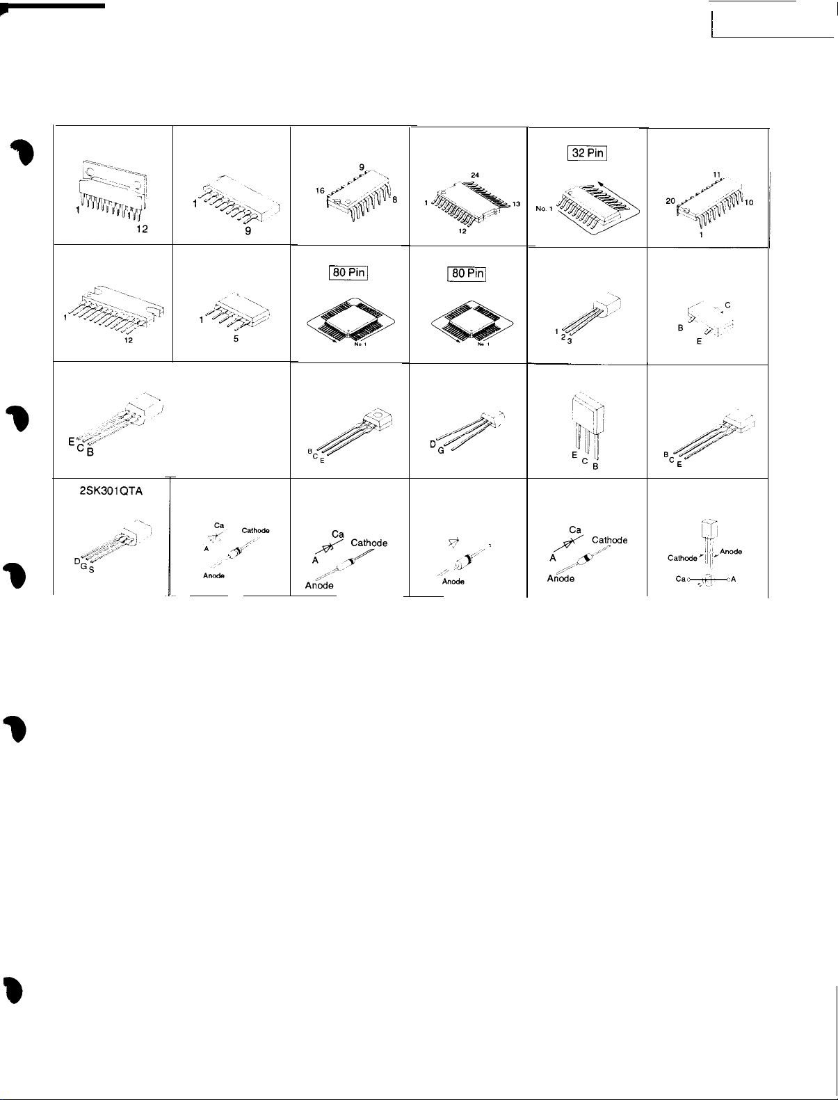
Terminal Guide of
AN71 35
BA3936
AN7205
BA7755A
2SC1684QTA
2SC1684RTA
2SC1684STA
MA4056N-MTA
ICs,
Transistors & Diodes
AN7317
M38222M2051
pmiq
2SC2785FTA
RVDMTZ5RGBTA
RVDMTZ6R8BTA
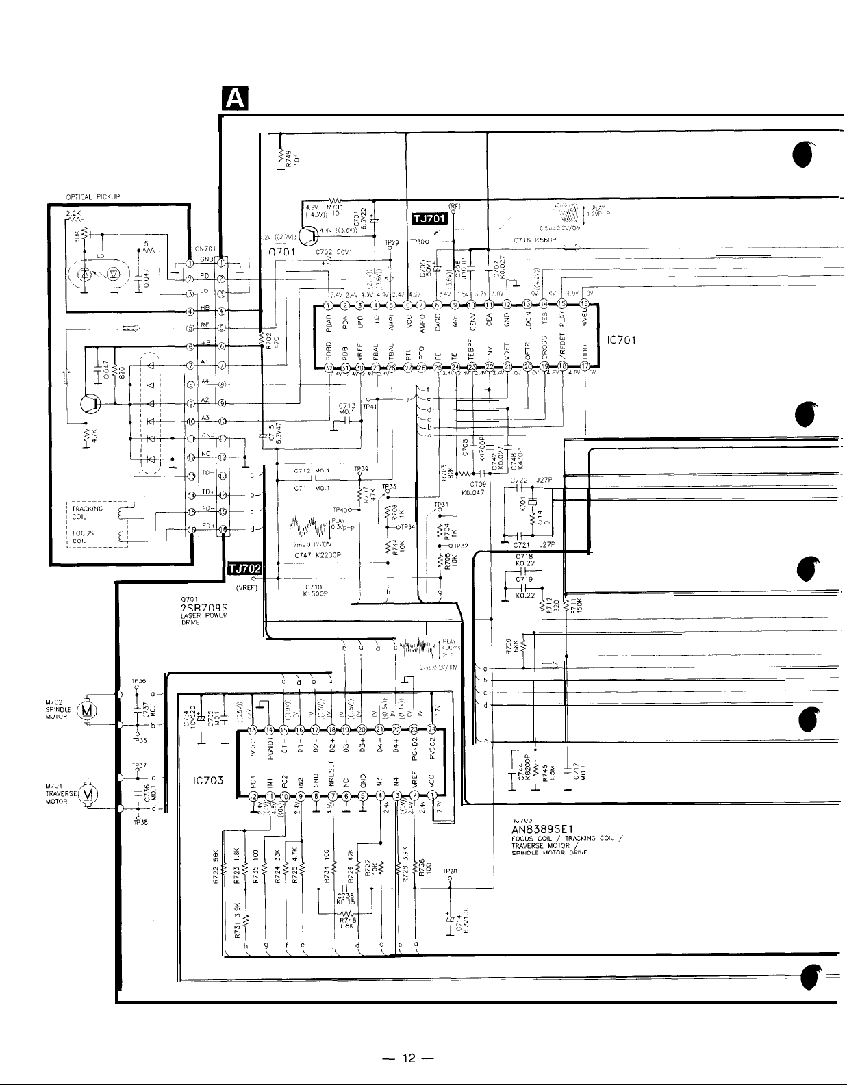
AN8389SE1
MN66271
pFq
2SJ40CDTA
,,_+
,’
“,I ,/’
4
DG
S
RL203M11
q
A
,,,,
4.7”’
Ca
RA
*>
‘.,
’
Cathode
i
AN8802SCE1
132
PST600DTA
BN1A4MTA
RVD1 SS1
33TA SLB55VRTE7
V
BA1442A
2SB709S
2SC 1740SRTA
RVTDTC114EST
-ll-
RX-DT30
n
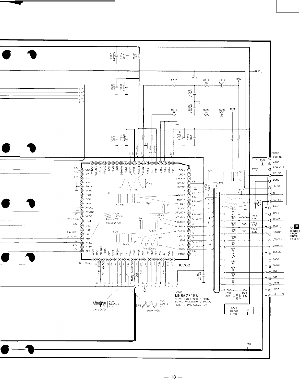
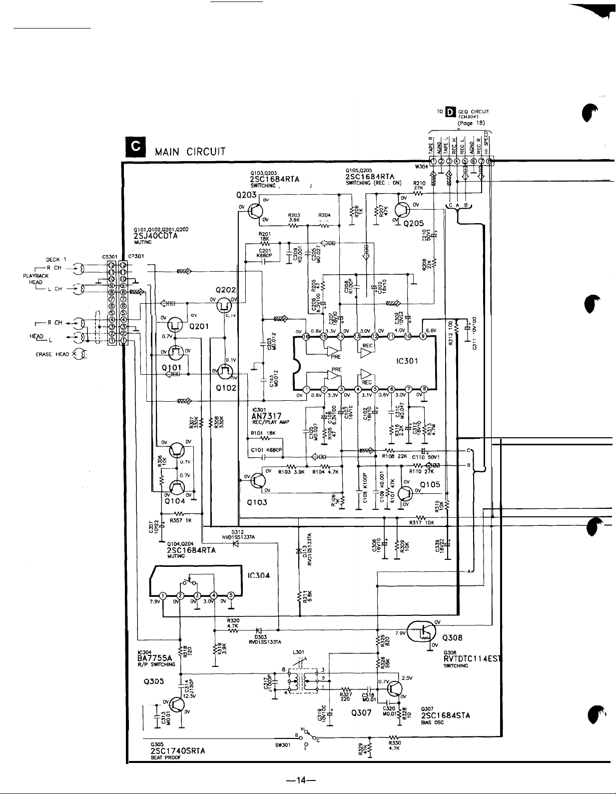
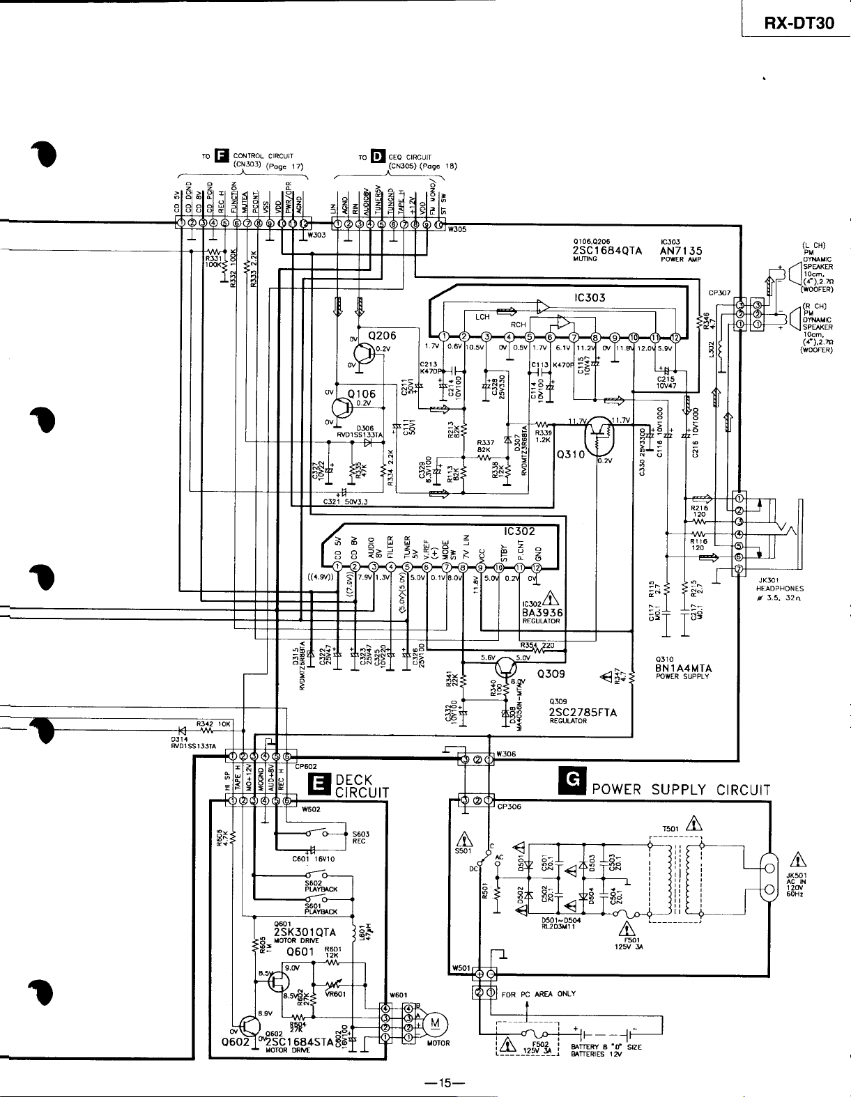
Schematic Diagram
A
SERVO CIRCUIT
13
ZY
;z
lC701
AN8802SCE1
SERVO AMP
V
RX-DT
P2
r
_
_
_
_
_
_
_
_
_
_
_
RX-DT30
n
Schematic Diagram
I
2SC1684RTA
WXHING
(HIGH SPEED)
a101.0102.0201.0202
;st$OCDTA
‘JO1
1
-R
REC/PtAY
“EL
DECK 2
CH
CH
-1
11
il
Q204
6::
”
Kz.307
AN731 7
REC/PLAY
RIO,
I*K
cto,
K68oP
AMP
tzl
J
I
0305
2SC1740SRTA
BEN PROcf
-14-
 Loading...