

Panasonic RXD-27-E, RXD-27-EB, RXD-27-EG Service manual

TD0404025C2
Portable Stereo CD System
RX-D27E
RX-D27EG
RX-D27EB
Traverse Deck: RAE0240Z-M Mechanism Series
Colour
(S)............Silver Type
1
SPECIFICATIONS
Specifications
RADIO
Frequency Range
FM 87.50~108.00 MHz (50
kHz steps)
AM 522~1629 kHz (9 kHz
steps)
TAPE RECORDER
Track System 4 track, 2 channel, stereo
Monitor system Variable sound monitor
Recording system AC bias
Erasing system Multi Pole magnet
Frequency range
Normal position 50 ~ 12000 Hz
CD PLAYER
Sampling frequency 44.1 kHz
Decoding 16 bit linear
Beam source Semiconductor laser
(wavelength 780 nm)
No. of channels 2 channel, stereo
Wow and flutter Less than possible
measurement data
D/A converter 1 bit DAC
Output Phones : 3.5 mm stereo
(32
Power output (RMS) 2.0W + 2.0W (MAX)
Power Requirement
AC 230-240 V, 50 Hz
Power Consumption 13 W
Battery 9 V (six R14/LR14, C, UM-
2 batteries)
Do not use rechargeable type batteries.
Memory back-up 4.5 V (three R6/LR6, AA,
UM-3 batteries)
Do not use rechargeable type batteries.
Speakers
Full range 8 cm 4
Dimensions (W x H x D) 408 x 163 x 273 mm
Mass 3.3 kg without batteries
x 2
)
GENERAL
Jacks
Notes:
1. Specifications are subject to change without notice.
2. Mass and dimensions are approximate.
2

1
1. Before Repair and Adjustment
Disconnect AC power, discharge Power Supply Capacitors C116, C216, C317 through a
10
, 5 W resistor to ground. DO NOT SHORT-CIRCUIT DIRECTLY (with a screw driver
blade, for instance), as this may destroy solid state devices.
After repairs are completed, restore power gradually using a variac, to avoid over
current.
Current consumption at AC 230 V, 240 V, 50 Hz in NO SIGNAL mode should be ~45 mA
respectively.
2. Protection Circuitry
The protection circuitry may have operated if either of the following conditions are
noticed:
- No sound is heard when the power is turned on.
- Stops during a performance.
The function of this circuitry is to prevent circuitry damage if, for example, the positive
3
and negative speaker connection wires are “shorted”, or if speaker systems with an
impedance less than the indicated rated impedance of the amplifier are used.
If this occurs, follow the procedure outlines below:
1. Turn off the power.
2. Determine the cause of the problem and correct it.
3. Turn on the power once again after one minute.
Note:
When the protection circuitry functions, the unit will not operate unless the power is
first turned off and then on again.
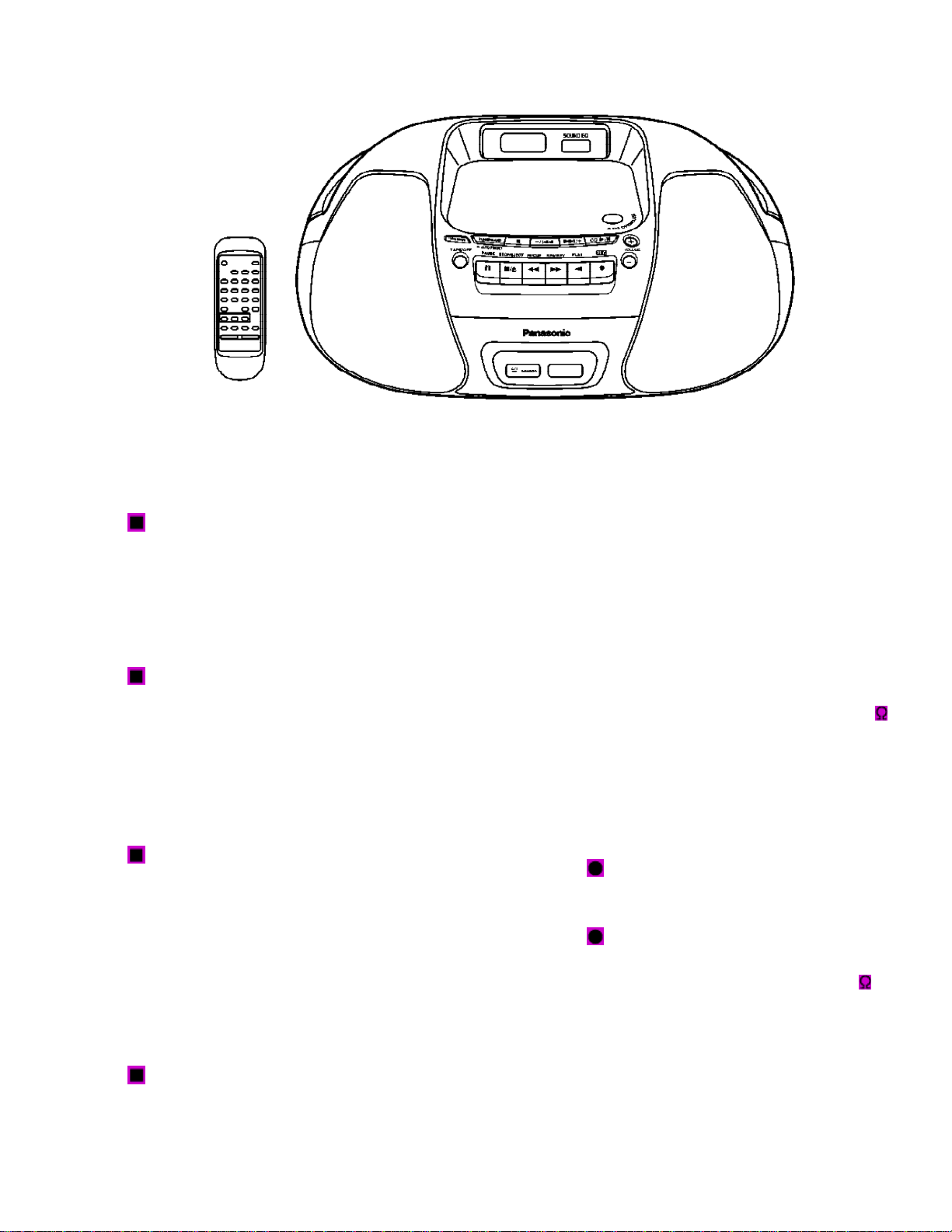
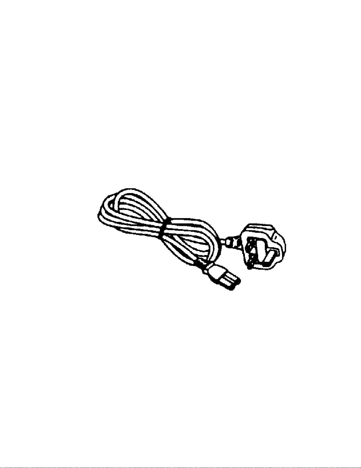
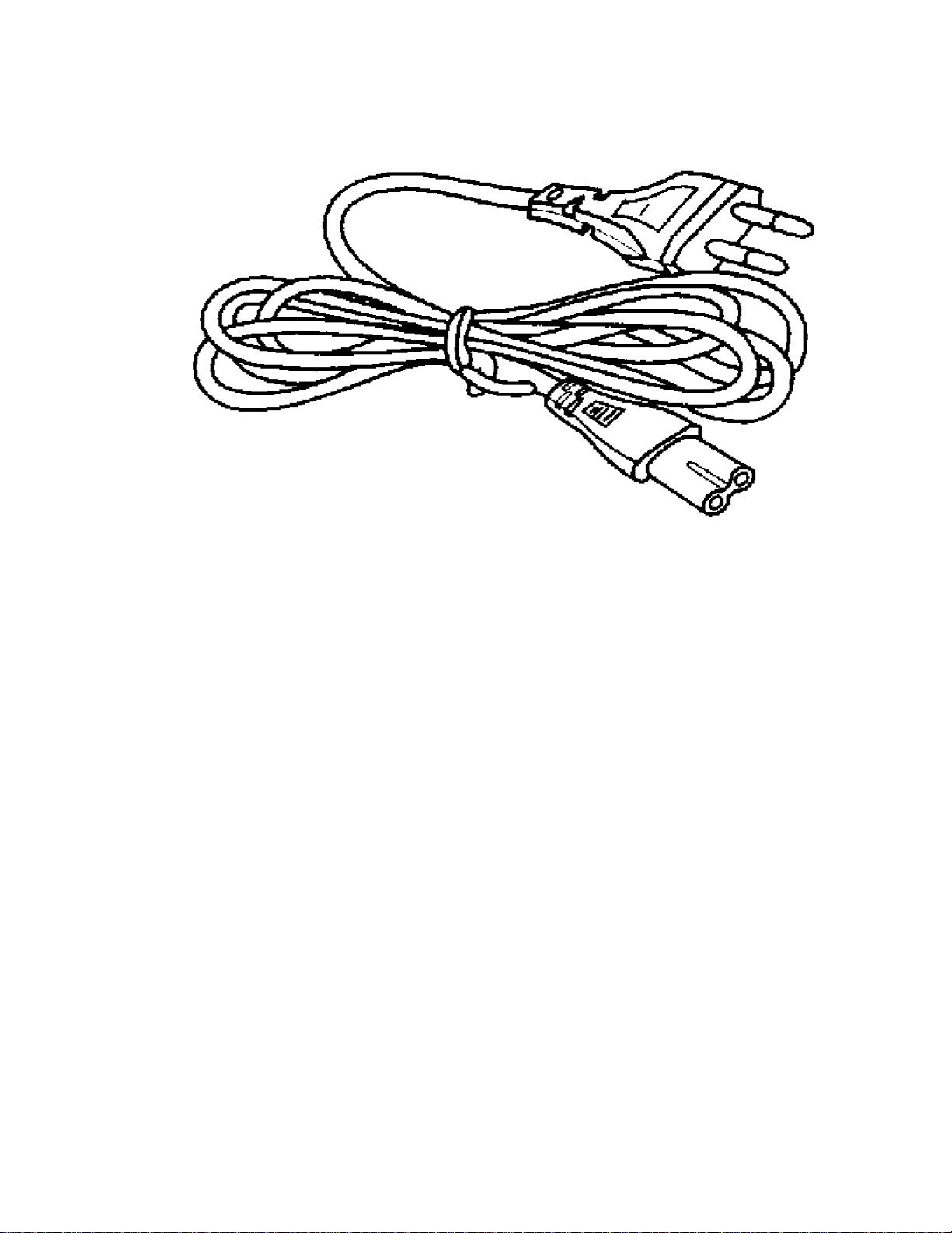
3. Accessories
- AC Main Lead (EB)......1 pc
- AC Main Lead (E/EG)......1 pc
4
- Remote control transmitter......1 pc
5

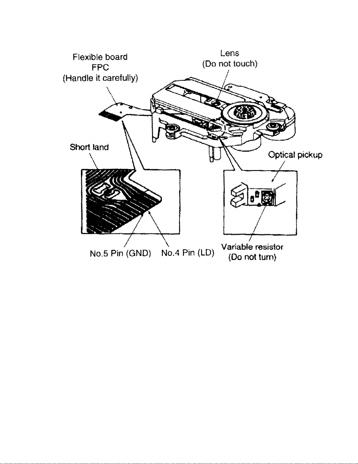
4. Handling Precautions For Traverse Deck
The laser diode in the traverse deck (optical pickup) may break down due to potential
difference caused by static electricity of clothes or human body. So, be careful of
electrostatic breakdown during repair of the traverse deck (optical pickup).
- Handling of traverse deck (optical pickup)
1. Do not subject the traverse deck (optical pickup) to static electricity as it is
extremely sensitive to electrical shock.
2. To prevent the breakdown of the laser diode, an antistatic shorting pin is inserted
into the flexible board (FFC board).
3. Take care not to apply excessive stress to the flexible board (FFC board). When
removing or connecting the short pin, finish the job in as short time as possible.
6

4. Do not turn the variable resistor (laser power adjustment). It has already been
adjusted.
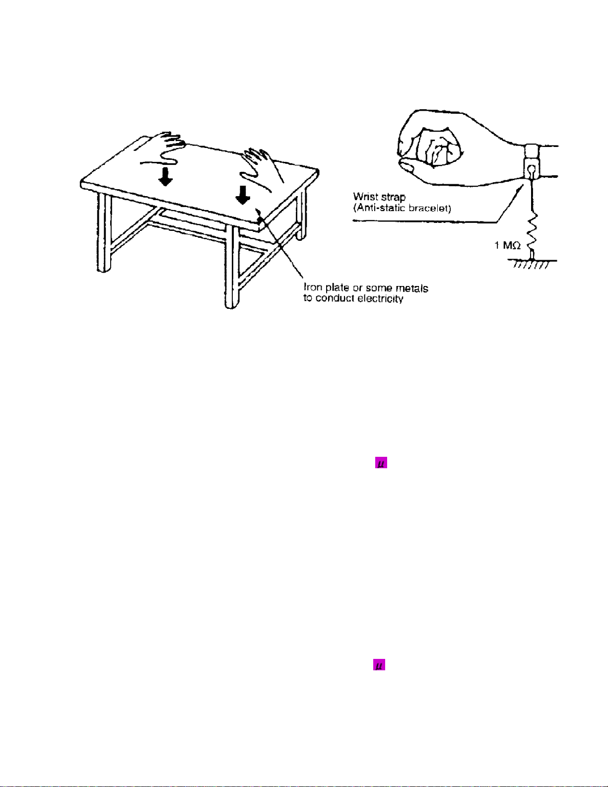
- Grounding for electrostatic breakdown prevention
1. Human body grounding
Use the anti-static wrist strap to discharge the static electricity from your body.
2. Work table grounding.
Put a conductive material (sheet) or steel sheet on the area where the traverse deck
(optical pickup) is place, and ground the sheet.
Caution:
The static electricity of your clothes will not be grounded through the wrist strap. So,
take care not to let your clothes touch the traverse deck (optical pickup).
on when replacing the Traverse Deck
The traverse deck has a short point shorted with solder to protect the laser diode
against electrostatics breakdown. Be sure to remove the solder from the short point
before making connections.
7
8
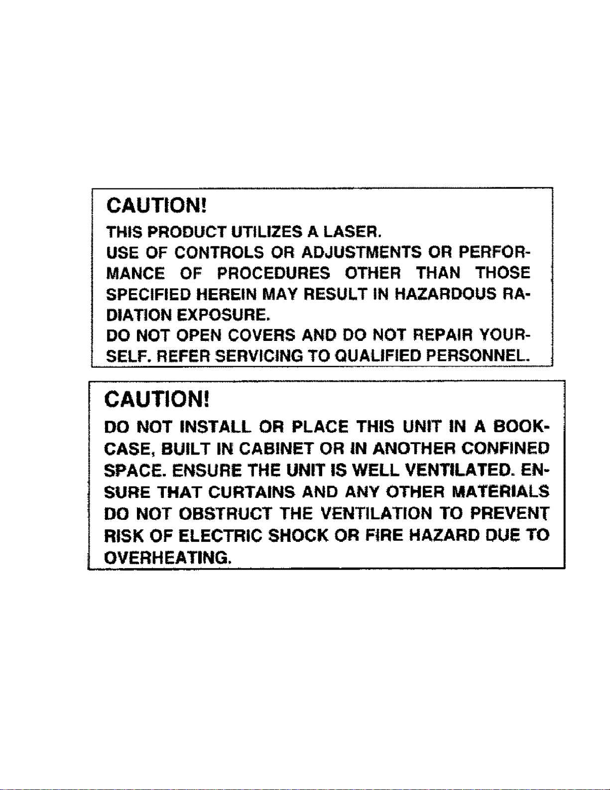
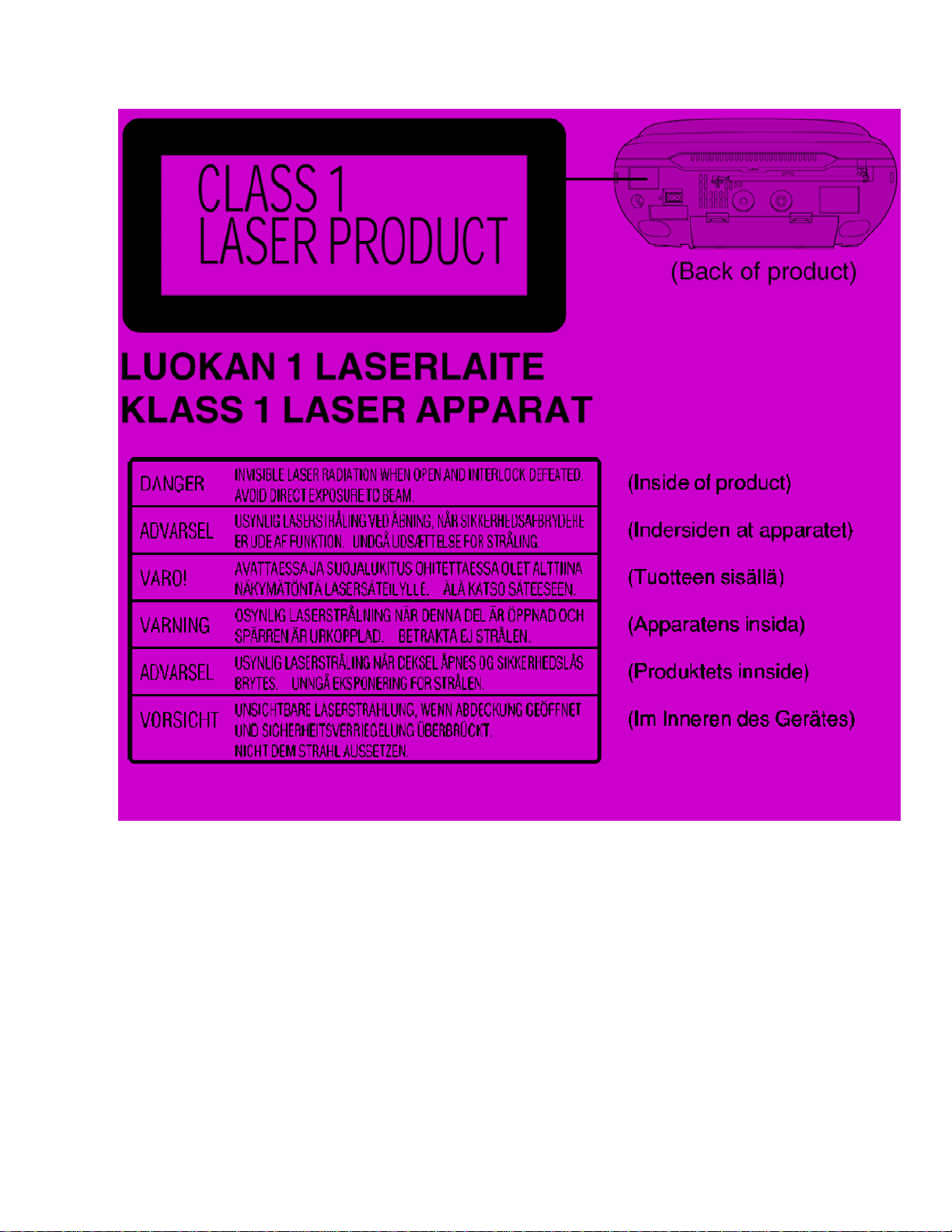
5. Precaution of Laser Diode
CAUTION:
This product utilizes a laser diode with the unit truned “ON”, invisible laser radiation is
emitted from the pick up lens.
Wavelength : 780 nm
Maximum output radiation power from pick up : 100
Laserradiation from pick up unit is safety level, but be sure the followings:
1. Do not disassemble the optical pick up unit, since radiation from exposed laser diode
is dangerous.
2. Do not adjust the variable resistor on the pick up unit. It was already adjusted.
3. Do not look at the focus lens using optical instruments.
4. Recommend not to look at pick up lens for a long time.
ACHTUNG:
Dieses Produkt enthält eine Laserdiode. Im enigeschalteten Zustand wird unsichtbare
Laserstrahlung von der Lasereinheit abgestrahlt.
Wellenlänge : 780nm
Maximale Strahlungsleistung der Lasereinheit : 100
DieStrahlung an der Lasereinheit ist ungefährlich, wenn folgende Punkte beachtet
werden:
W/VDE
W/VDE
9
1. Die Lasereinheit nicht zerlegen, da die Strahlung an der freigelegten Laserdiode
gefährlich ist.
2. Den werkseitig justierten Einstellregler der Lasereinhit nicht verstellen.
3. Nicht mit optischen Instrumenten in die Fokussierlinse blicken.
4. Nicht über längere Zeit in die Fokussierlinse blicken.
10
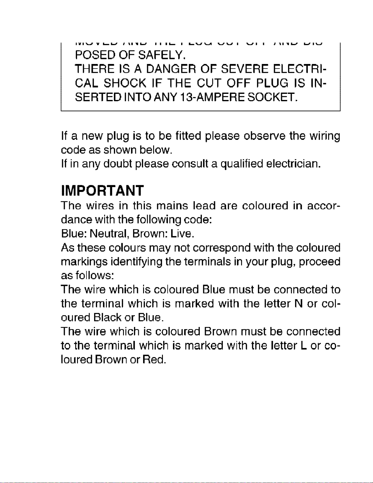
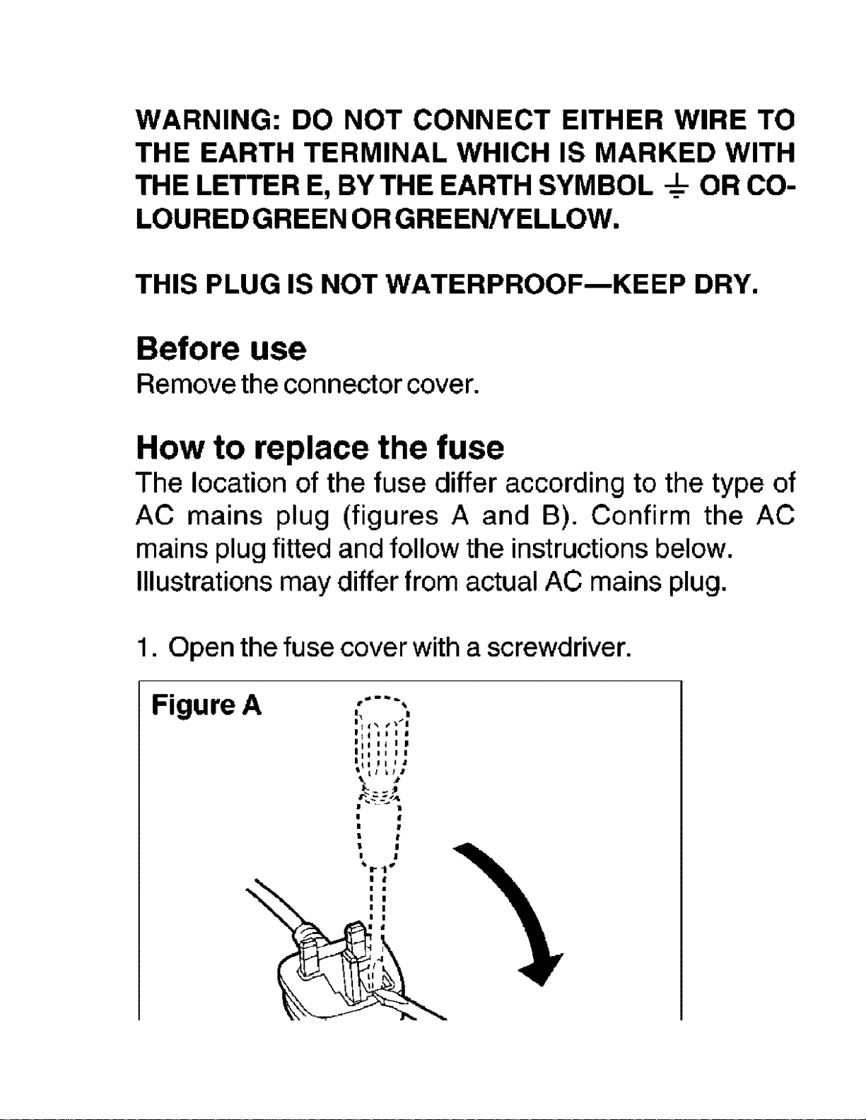
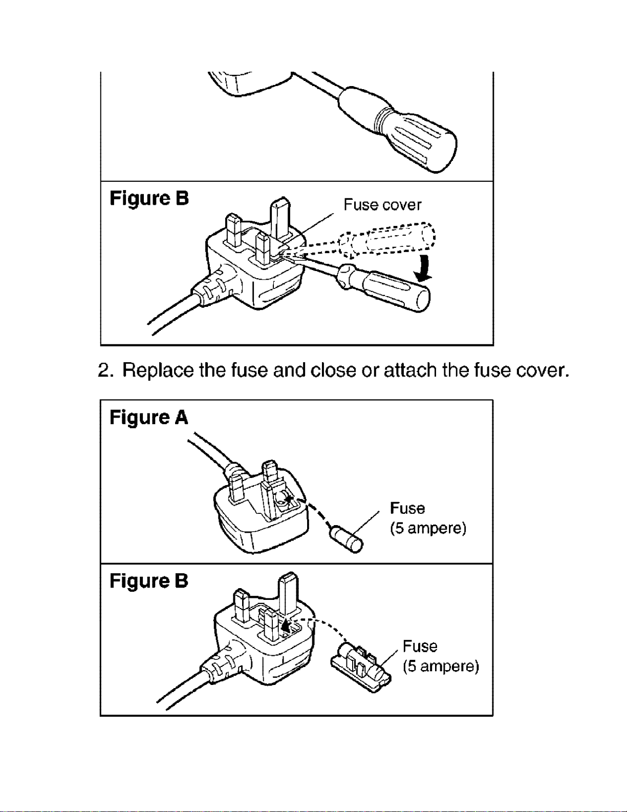
6. Caution for AC Main Lead
1112131415

7. Location of Controls
8. Self-Diagnostic Functions
8.1. Setting of the Self-Diagnostic Mode
1. Switch the SELECTOR to CD and set to TAPE STOP state. (CD PLAY STOP)
2. Press the
keys for another two seconds without releasing the
the Self-Diagnostic mode.
3. At the state of [ T ] display, operate as follows:
- Open the CD lid and close it right away.
- Start recording TAPE, and STOP it at once.
4. Press
- Self diagnostic results, i.e. the memorized errors during actual operations and
the result of above-mentioned operation shall be displayed alternately.
- If there is no error, the aforementioned display [ T ], shall be kept.
- If the operation in the above mentioned in item 4 is made without executing the
procedure in item 3, [ H16 ] and [ F69 ] shall be displayed.
/CLEAR for the first two seconds and followed by the FAST FORWARD
/CLEAR key.
8.2. Display Location
/CLEAR key, it shall enter into
16
8.3. Display Content
No. Abnormal Items Error
Display
1 CLOSE SW abnormal H16 Detect error during closing operation and memorised it
as an error.
2 REST SW abnormal F15
3
Transmission error between
CD servo LSI and micon
4 Low battery detecter U01 Detect the battery when the battery is low.
F26
Under normal operation (Self-Diagnostic Mode
inclusive), this error occurs when the REST SW ON is
not detected within the specified time (5000 ms) and
shall be memorised.
Under normal operation (Self-Diagnostic Mode
inclusive), this error occurs when the selection is set to
CD and SENSE =’H’ is detected and SENSE =’L’ is not
detected within a fail-safe time (20 ms) after system
command transmission was sent.
Method of detection
9. Troubleshooting Guide
17
10. Operation Checks and Component Replacement
Procedures
1. This section describes procedures for checking the operation of the major printed
circuit boards and replacing the main components.
2. For reassembly after operation checks or replacement, reverse the respective
procedures special ressembly procedures are described only when required.
3. Select item from the following index when checks or replacement are required.
Contents
- Disassembly Procedure for each major P.C.B.
1. Replacement of Handle.
2. Replacement of Up Cabinet ,Back Cabinet,Front Cabinet.
18

3. Checking for Deck P.C.B and Tuner P.C.B.
4. Replacement of Pinch Roller, Eraser Head, Record / Play back Head.
5. Replacement of Motor, Main Belt, Forward Belt.
6. Replacement of Traverse Deck.
7. Replacement of CD Cover.
8. Replacement of Cassette Cover.
9. Troubleshooting for Cassette Tape Entanglement.
10. Checking for Main PCB and CD Servo P.C.B.
Warning:
This product uses a laser diode. Refer to “Precaution of Laser Diode”.
10.1. Removal of the handle ass’y
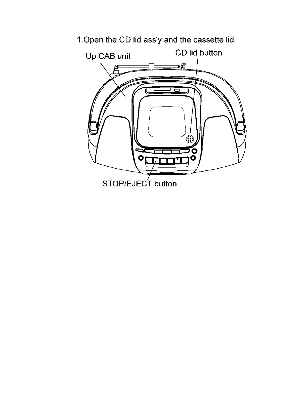
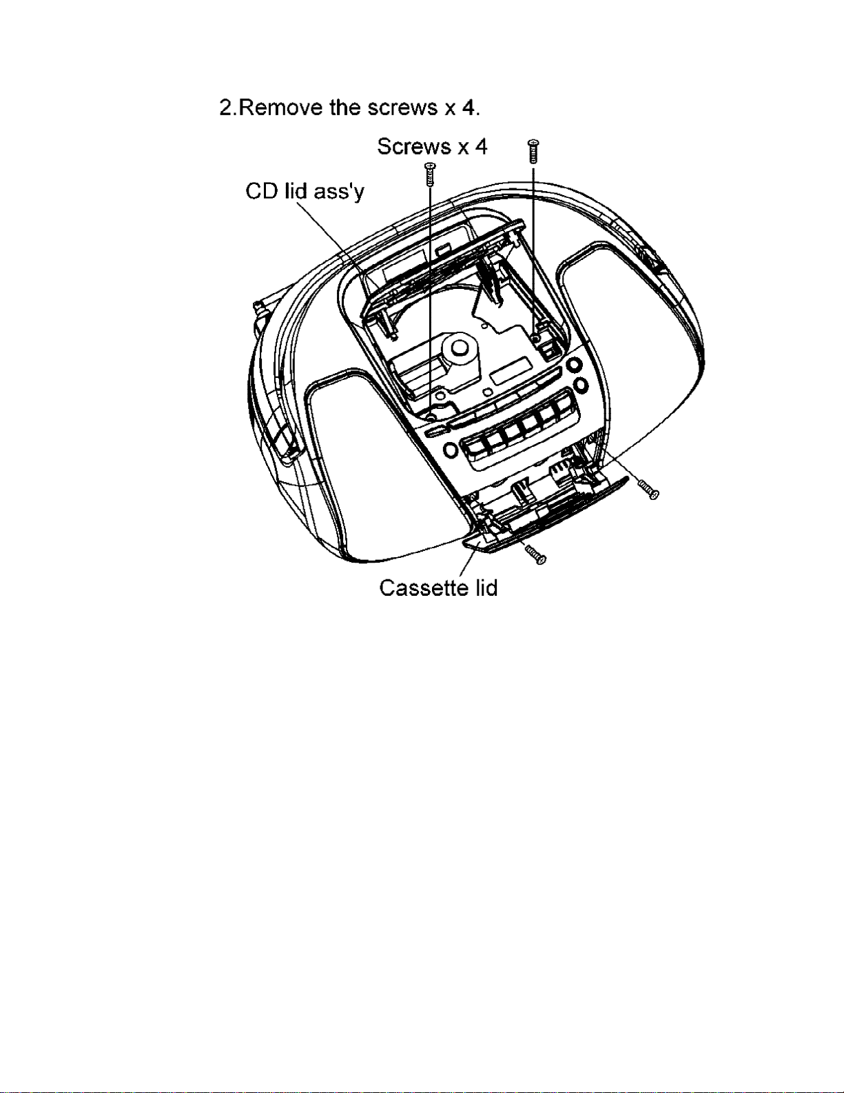
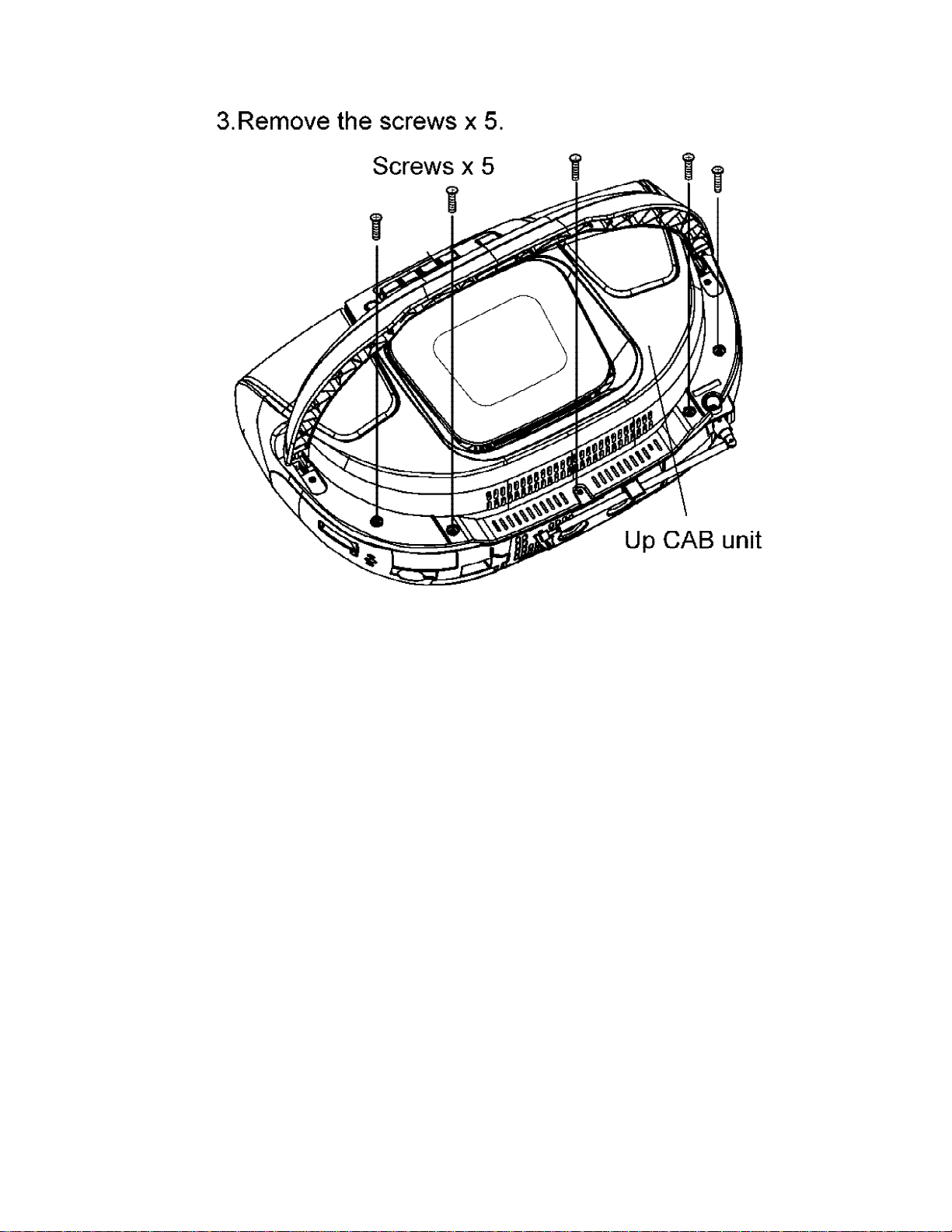
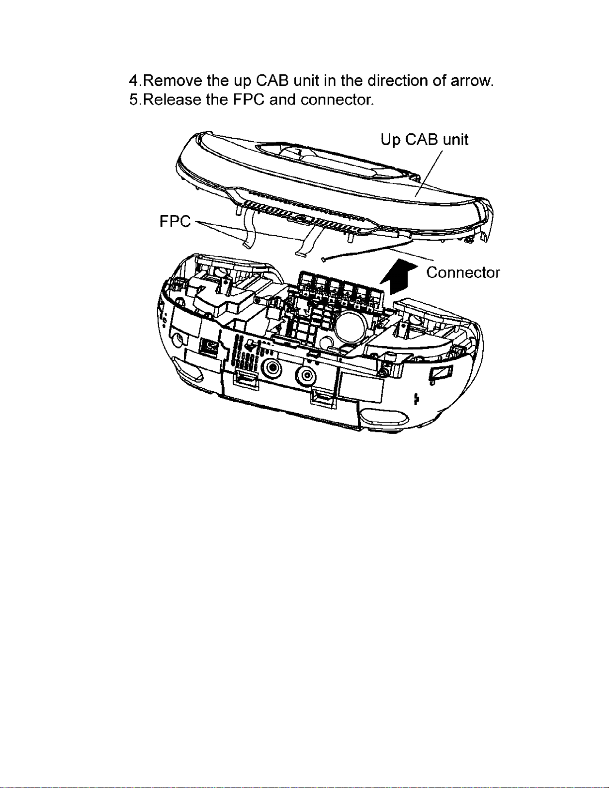
10.2. Removal of the up cabinet unit
192021
22
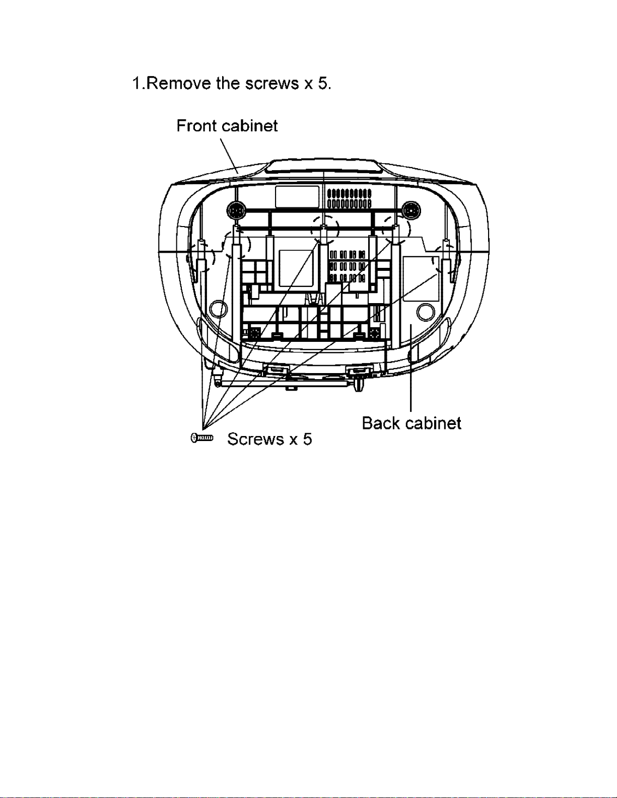
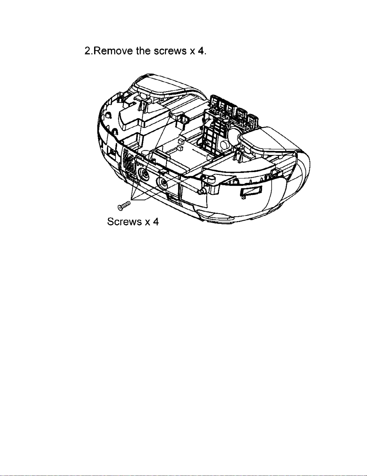
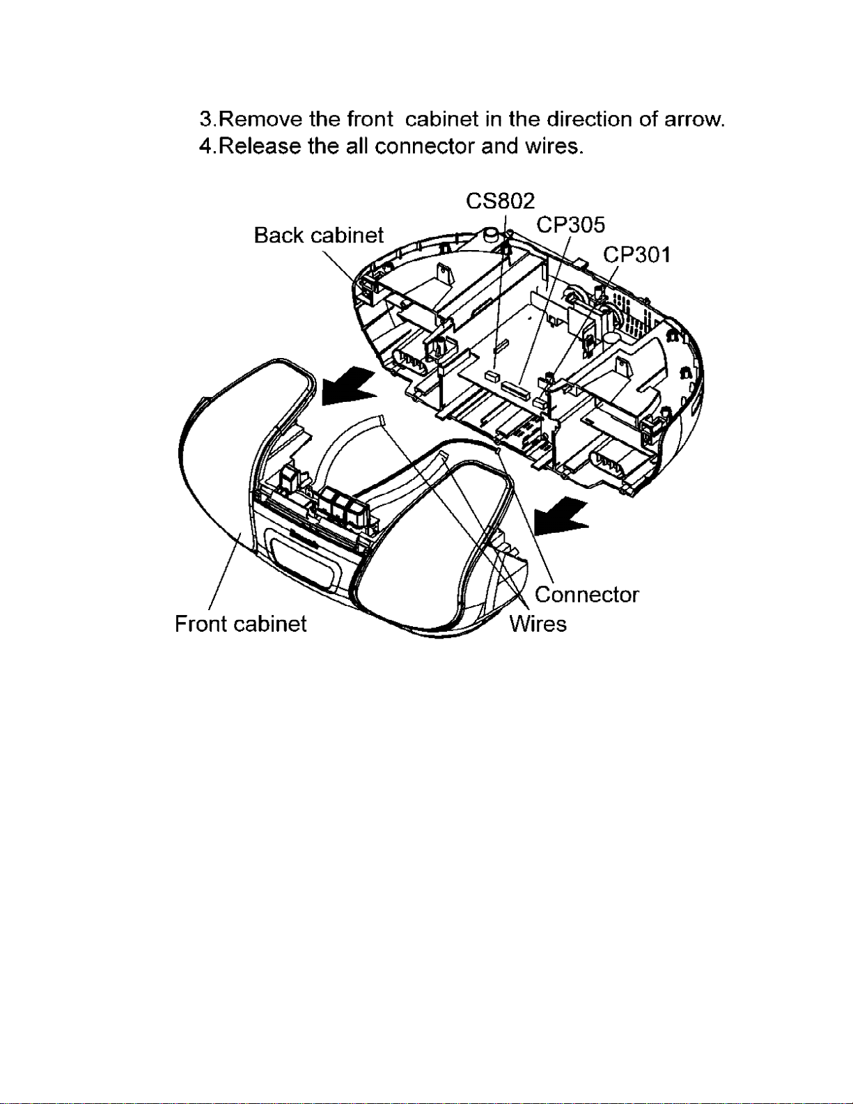
10.3. Removal of the back cabinet and front cabinet
232425
10.4. Removal of the main P.C.B.
26
 Loading...