

Panasonic RX550, RX450, RS485 Installation Manual
Building Block Video Ltd.
17 Apex Park,
Diplocks Industrial Estate,
Hailsham, East Sussex, BN27 3JU UK.
Tel: +44(0)1323 842727
Fax: +44(0)1323 842728
Support: +44(0)1323 444600
www.bbvcctv.com
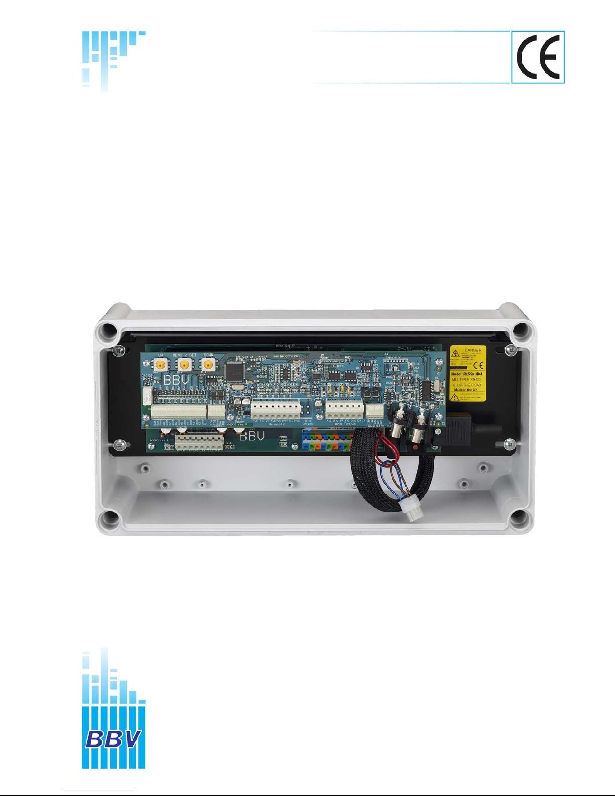
Model Shown: RX550
RX550 and RX450
Panasonic RS485 receivers
Installation
Guide

Rx450AC Rx550DC MK3 Installation Manual - V19 30Sep05.doc Page 2/28
1. PRE-INSTALLATION CHECKS AND SAFETY PROCEDURES
UNPACKING
Check Packaging - Upon taking delivery of the unit, inspect the packaging for signs of
damage. If damage has occurred, advise the carriers and/or the suppliers immediately.
Check Contents - Upon taking delivery of the unit, unpack the receiver carefully and
check that all the items are present and correct. If any items are missing or damaged,
contact your equipment dealer.
Retain Packaging - The shipping carton is the safest container in which to transport the
unit. Retain undamaged packaging for possible future use.
IMPORTANT SAFETY PRECAUTIONS
Read Instructions - All relevant safety, installation and operating instructions should be
read before attempting to install, connect or operate the unit.
Retain Instructions - All safety, installation and operating instructions should be retained
for future reference.
Heed Warnings - All warnings on the unit and in any relevant safety, installation or
operating instructions should be adhered to.
Cleaning - Unplug the unit from the power outlet before cleaning. Do not use liquid
cleaners or aerosol cleaners. Use a damp cloth for cleaning.
Attachments - Do not use attachments not recommended by the product manufacturer
as they may cause hazards.
Water and Moisture - Do not expose the internal electronics of this unit to water or
dampness; for example, in an unprotected outdoor installation, or in any area classified
as a wet location. The unit as supplied conforms to ingress protection rating IP 67. This
rating will be affected by any holes made in the enclosure. Cable entry points should be
protected by the use of suitably rated glands and/or flexible conduit. It is not necessary to
make further holes in the enclosure for mounting purposes, as mounting holes are
provided at the corners of the enclosure outboard of the seal between enclosure and lid.
Accessories - Do not attach this unit to an unstable stand, bracket or mount. The unit
may fall, causing serious injury to a person and serious damage to the unit.
Power Sources - This unit should be operated only from the type of power source
indicated on the manufacturer’s label. If you are not sure of the type of power supply you
intend to use, consult your equipment dealer or local power company. For units intended
to operate from battery power or other sources, refer to operating instructions.
Power Connector - This unit is equipped with connector mounted at the edge of the PCB
for mains power input. Do not attempt to alter this connector in any way.
Power Cord Protection - Power supply cords should be routed so that they are not likely
to be trapped, pinched or otherwise damaged by items in close proximity to them,
whether inside the unit or outside it. Particular attention should be paid to cords at plugs,
connection units and the point of exit from the unit.

Rx450AC Rx550DC MK3 Installation Manual - V19 30Sep05.doc Page 3/28
Overloading - Do not overload outlets and extension cords, as this can result in fire or
electric shock.
Object and Liquid Entry - Never push objects of any kind into the unit, as they may
touch dangerous voltage points or short out parts that could result in fire or electric shock.
Never spill liquid of any kind on or inside the unit.
Servicing - Servicing of the unit should only be undertaken by qualified service
personnel, as opening or removing covers may expose you to dangerous voltages or
other hazards.
Damage Requiring Service - Servicing by qualified personnel should be carried out
under the following conditions:
(a) When the power-supply cord or plug is damaged;
(b) If liquid has been spilled, or objects have fallen into, the unit;
(c) If the internal electronics of the unit have been exposed to rain or water;
(d) If the unit does not operate normally by following the operating instructions. Adjust
only those controls that are covered by the operating instructions, as improper
adjustment of other controls may result in damage and will often require extensive
work by a qualified technician to restore the unit to normal operation;
(e) If the unit has been dropped or the enclosure is damaged;
(f) If the unit exhibits a distinct change in performance. This indicates a need for
service.
Replacement Parts - If replacement parts are required, ensure that only replacement
parts recommended by the product manufacturer are used.
Safety Check - Upon completion of any service or repairs to the unit, safety checks
should be performed to ensure that the unit is in proper operating condition.
Coax Grounding - If an outside cable system is connected to the unit, be sure the cable
system is grounded.
Pre-installation Checks - It is recommended that the unit be bench-tested prior to
installation on the site.
Safety During Installation or Servicing - Particular care should be taken to isolate the
pan/tilt head in order to prevent operation while engineering work is being carried out on
the receiver.
Adhere to Safety Standards - All normal safety precautions as laid down by British
Standards and the Health and Safety at Work Act should be observed.
WARNING
TO PREVENT DANGER OF FIRE OR SHOCK, DO NOT EXPOSE THE INTERNAL
COMPONENTS OF THIS EQUIPMENT TO RAIN OR MOISTURE.
DO NOT OPERATE THE UNIT WITH ANY INTERNAL COVERS REMOVED.
DANGEROUS VOLTAGES ARE PRESENT ON THE POWER SUPPLY. THE UNIT
MUST ONLY BE SERVICED BY QUALIFIED PERSONNEL.

Rx450AC Rx550DC MK3 Installation Manual - V19 30Sep05.doc Page 4/28
2. INTRODUCTION
GENERAL
The Rx450 is designed to control 24Vac/230Vac operated pan/tilt mechanisms and the
Rx550 is designed to control 24Vdc high/variable speed heads from a Panasonic RS485
telemetry control system.
The receivers can be connected using either a daisy chained or star wired RS485
network depending upon the model of Panasonic controller used. 4 wired star wired
telemetry is preferred. If the control system has only a single telemetry output a BBV
STARCARD/CONVERTER can be used to allow star wiring of the site.
The receiver is supplied in an IP67 rated enclosure. It will be necessary to make suitable
holes in the enclosure to permit cable entry and exit. Adequately rated cable glands and
or flexible conduit should be used at all times to avoid compromising the protection
afforded by the enclosure as supplied. Any holes made in the enclosure for any other
purpose should be sealed with a non-hardening waterproof sealant, taking care to ensure
that the internal electronics are not contaminated. Enclosure mounting holes are
provided at the corners of the enclosure outboard of the seal between enclosure and lid.

Rx450AC Rx550DC MK3 Installation Manual - V19 30Sep05.doc Page 5/28
3. Rx450 Technical Specification
Power Requirements 230Vac or (110Vac or 24Vac as factory fitted option)
Max Load 5A @ 230V (1150 W)
Receiver Current Draw 24VA max
Fuses Auxiliary fuse F2 5A T (20mm ceramic cartridge)
Outputs 8 single pole relays (snubbed)
1. Left Motor 5. Autopan (Interlocked with Pan)
2. Right Motor 6. Lights (1000W max)
3. Up Motor 7. Wash
4. Down Motor 8. Wipe
Facilities LED readout for continual system status.
Programming menu with On Screen Display.
Gain REMOTELY ADJUSTABLE
Video launch amplifier provided with cable length adjustment
12Vdc/500mA camera power provided.
Colour coded outlets – live, neutral, earth and low voltage.
Telemetry Signal 2 or 4 wire Panasonic RS485
Auto Iris Output Returns to original setting 15 seconds after key release. Level
programmable from controller.
Video Input 1v p-p 75Ω terminated input via BNC socket.
Video Output 1v to 4v p-p 75Ω impedance via BNC socket.
Lens Drive REMOTELY ADJUSTABLE
Adjustable via menu between 6 – 12Vdc. Inching speed selectable via
menu between 0 – 12Vdc. 1 second inching built in. Provides drive for
Zoom & Focus. Each lens drive carries red and green LEDs to indicate
direction and drive voltage.
Presets Inputs are provided for pan, tilt, zoom & focus preset feedback pots.
These are 10 bit resolution. Up to 64 full-scene presets can be stored
within the receiver, i.e. pan, tilt, zoom, focus.
Other Outputs RS485 Serial port available to drive advance features on selected
cameras.
Additional Information Autopan auxiliary output or software Random Pan
Sequential preset patrol. The preset dwell is programmable individually.
Datum - return to preset 1, start preset patrol or random pan after menu
programmable duration of inactivity.
Iris output - either direct drive for 3 motor lens or Autoiris override voltage
for Seiko/Cosmicar lenses etc.
8 alarm inputs, volts free normally closed contacts. A single opening volts
free contact sums the alarms either immediately or as the preset is
approached. If a video transmission system is activated with the alarm
output, then setting the alarm to delayed prevents unwanted frames being
transmitted.
Options 24Vac/230Vac output is link selectable with link J3
Boxed Dimensions Width: 380mm, Length: 190mm, Height: 130mm
Weight
3.43kg

Rx450AC Rx550DC MK3 Installation Manual - V19 30Sep05.doc Page 6/28
Rx550 Technical Specification
Power Requirements 230Vac or (110Vac or 24Vac as factory fitted option)
Max Load 5A @ 230V (1150 W)
Receiver Current Draw Maximum of 100VA max
Fuses Auxiliary fuse F2 5A T (20mm ceramic cartridge)
Outputs Linear 0-24Vdc output for pan & tilt motor drive
Switched 24Vdc output to drive motor brakes.
Lens drive adjustable between 5-12Vdc 150mA max
Total maximum of pan/tilt/lens and 24Vac auxiliary is 100VA.
Switched AC output to drive Wash/Wipe/Lights(1000W max)
Facilities LED readout for continual system status.
Programming menu with On Screen Display.
Gain REMOTELY ADJUSTABLE
Video launch amplifier provided with cable length adjustment
12Vdc/500mA camera power provided.
Colour coded outlets – live, neutral, earth and low voltage.
Telemetry Signal 2 or 4 wire Panasonic RS485
Auto Iris Output Returns to original setting 15 seconds after key release. Level
programmable from controller.
Video Input 1v p-p 75Ω terminated input via BNC socket.
Video Output 1v to 4v p-p 75Ω impedance via BNC socket.
Lens Drive REMOTELY ADJUSTABLE
Adjustable via menu between 6 – 12Vdc. Inching speed selectable via
menu between 0 – 12Vdc. 1 second inching built in. Provides drive for
Zoom & Focus. Each lens drive carries red and green LEDs to indicate
direction and drive voltage.
Presets Inputs are provided for pan, tilt, zoom & focus preset feedback pots.
These are 10 bit resolution. Up to 64 full-scene presets can be stored
within the receiver, i.e. pan, tilt, zoom, focus for each preset.
Other Outputs RS485 Serial port available to drive advance features on selected
cameras.
Additional Information Software Random Pan
Sequential preset patrol. The preset dwell is programmable individually.
Datum - return to preset 1, start preset patrol or random pan after menu
programmable duration of inactivity.
Iris output - either direct drive for 3 motor lens or Autoiris override voltage
for Seiko/Cosmicar lenses etc.
8 alarm inputs, volts free normally closed contacts. A single opening volts
free contact sums the alarms either immediately or as the preset is
approached. If a video transmission system is activated with the alarm
output, then setting the alarm to delayed prevents unwanted frames being
transmitted.
Options 24Vac/230Vac auxiliary outputs are link selectable with link J3
Boxed Dimensions Width: 380mm, Length: 190mm, Height: 130mm
Weight 3.43kg
Rx450AC Rx550DC MK3 Installation Manual - V19 30Sep05.doc Page 7/28
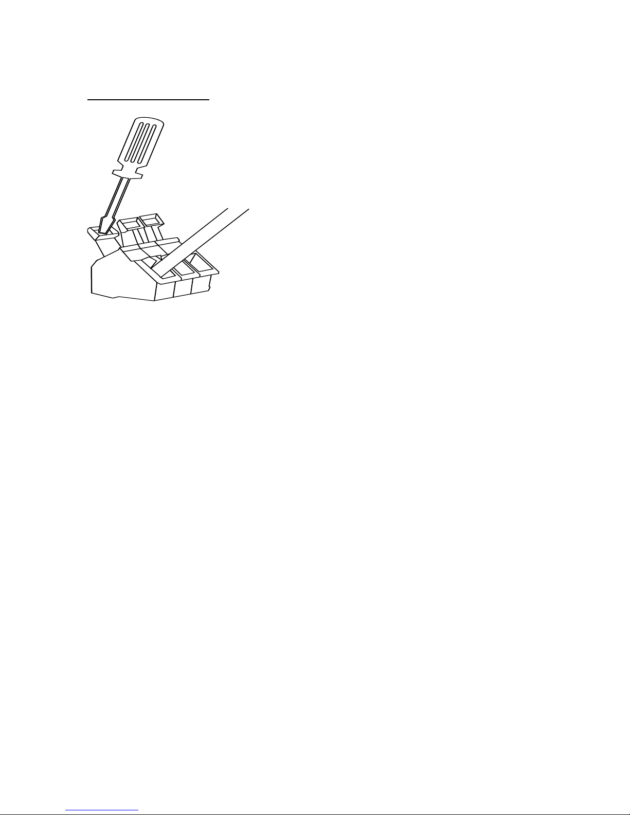
CABLE CONNECTION METHOD
Cage clamp connectors
The cage clamp connector is a simple-to-use method of attaching cables to PCBs quickly
and easily. Prepare cables as follows:
1. Use only cable between 0.08 and 2.5 mm²
2. Strip the cable to a length of 5 to 6 mm (0.23 in)
The correct method of attachment is as follows:
1. Press down the relevant terminal block lever with a suitable screwdriver;
2. Insert wire;
3. Remove screwdriver.
The procedure for detaching wires is the reverse of the 3 attachment steps, ensuring that
power is disconnected before starting.
Rx450AC Rx550DC MK3 Installation Manual - V19 30Sep05.doc Page 8/28
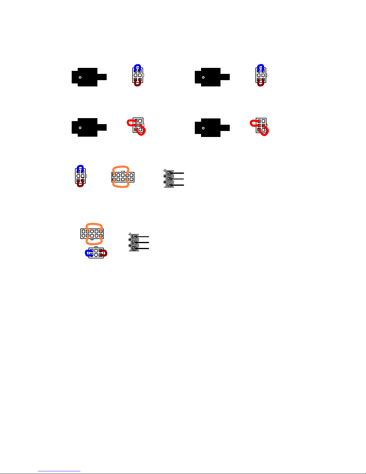
230Vac IN - 24Vac OUT
Supply IN J3 aux link
RED
RED
230Vac IN - 230Vac OUT
Supply IN
BLUE
BROWN
J3 aux link
110Vac IN - 24Vac OUT
(Factory fitted option)
Supply IN J3 aux link
RED
RED
110Vac IN - 110Vac OUT (Factory fitted option)
Supply IN
BLUE
BROWN
J3 aux link
24Vac IN - 24Vac OUT RX450 Mk 2 SERIES
(Factory fitted option)
J2
Supply IN
24Vac
24Vac
GND
J1
BLUE BROWN
J3
Supply IN
24Vac
24Vac
GND
J2
J1
BLUE
BROWN
J3
24Vac IN - 24Vac OUT RX550 Mk 2 SERIES
(Factory fitted option)
2 x ORANGE
2 x ORANGE
BBV RX450 - RX550 SERIES RECEIVER SUPPLY OPTIONS AND LINKS
Rx450AC Rx550DC MK3 Installation Manual - V19 30Sep05.doc Page 9/28
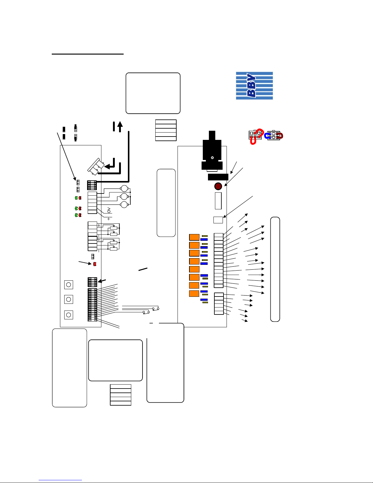
3. INSTALLATION
MAINS SUPPLY
1 2 3 4 5 6
1 2 3
4
5
6
7 8
ALARM OUT
Volts Free
N/C Contact
ALARM IN
Volts Free
N/C Contatcs
J7-PRESET
FOCUS
ZOO
M
PAN
TIL
T
J9-ALARMS
12Vdc
Out
0.75A
J1-VIDEO
UP MENU/SET DOWN
LOGIC/UPPER BOARD CONNECTIONS
J10-LENS
J4J11
POWER LED
ON = Power Present.
FLASH OFF = Telemetry Received.
FROM CAMERA
TO CONTROLLER
FOCUS
ZOO
M
IRI
S
*
J6
1 2 3 4 5 6 7 8 9
1
0
1
1
1
2
1
3
1
4
1
5
J4
J3 Output voltage select link.
RED links = 24Vac
BLUE/BROWN = supply voltage.
F3 AUX SUPPLY FUSE 5AT
N
E
U
TR
A
L
E
A
R
T
H
L
E
F
T
RIGHT
U
P
N
E
U
T
R
A
L
E
A
R
T
H
L
I
V
E
N
E
U
T
R
A
L
E
A
R
T
H
L
I
V
E
UNSWITCHED
OUTPUT
N
E
U
T
R
A
L
E
A
R
T
H
L
I
V
E
LIGHTS
AUTO
PAN
WIPE
WASH
PAN/TILT HEAD
PSU/LOWER BOARD CONNECTIONS
R
S
4
8
5
C
a
m
e
r
a
D
a
t
a
Local Self Test
Press UP & DOWN together.
Sequence is Left,Right,Down,Up,
Zoom In,Out,Focus Near,Far,Iris Open,
Close,Lights,AutoPan,Wash,Wipe
1TR
A
2TR
B
3GN
D
4RA
5RB
J11
CAMERA
DATA
Expanded
View
RS485 Termination links
= Terminated. End Of Line.
= Un-Terminated. Daisy Chained.
IRIS
The IRIS output can be configured as
motor drive or AutoIris Override voltage.
8 7 6 5 4 3 2 1
1TR
A
2TR
B
3GN
D
4RA
5RB
J4
RS485
Telemetry
Expanded
View
F2 PSU FUSE -3.15A
1 2 3 4 5 6
N
E
U
T
R
A
L
E
A
R
T
H
L
I
V
E
N
E
U
T
R
A
L
E
A
R
T
H
L
I
V
E
J6 and J4 Aux connectors Colour Coding
BLUE = NEUTRAL, ORANGE = LIVE, GREEN = EARTH
RX450 Mk3
PANASONIC
connection details
www.bbvcctv.com
97005 iss 4
24Vac
Mains
RED
RED
BLUE
BROWN
D
O
W
N
Camera Rx-J11
2 WIRE CONNECTION
A 1-TRA
B 2-TRB
GND 3-GND
4 WIRE CONNECTION
RA 1-TRA
RB 2-TRB
GND 3-GND
TA 4-RA
TB 5-RB
The receiver address is set from the
COMMUNICATIONS menu.
Power up with SW1, SW2 or SW3 pressed and
connect video monitor to J1 (Matrix out).
Navigate to COMMUNICATIONS menu.
UNLOCK and set address.
Alarm I/P 8
Alarm I/P 7
Controller Rx-J4
2 WIRE CONNECTION
TA 1-TRA
TB 2-TRB
GND 3-GND
4 WIRE CONNECTION
RA 1-TRA
RB 2-TRB
GND 3-GND
TA 4-RA
TB 5-RB
IRIS
FOCUS
ZOOM
As shipped, the auxiliary and head drive outputs are set to 24Vac with the RED linked
plug fitted to J3. To set the outputs to the same voltage as the receiver supply remove
the red plug and replace with the plug with the BROWN and BLUE links as shown above.
 Loading...