

Panasonic RR-US475E Service Manual
Power requirement : DC 3.0 V (2 AAA size/LR03
batteries)
Power output : 300 mW (max.)
Frequency response : 300 Hz to 5,000 Hz (HQ mode)
300 Hz to 3,400 Hz (FQ/SP mode)
S/N : 37 dB (HQ mode)
Output jack : Earphone, ø 3.5 mm; 0.5 mW 16
Ω
Input jack : Mic, ø 3.5 mm; 0.56 mV plug in
power
Speaker : 20 mm 8 Ω
Dimensions (W x H x D) :
© 2007 Matsushita Electric Industrial Co. Ltd.. All
rights reserved. Unauthorized copying and
distribution is a violation of law.
RR-US475E
Colour
(K) .... Black Type
Max dimensions : 39.3 mm x 105.5 mm x 17.2 mm
Cabinet dimensions : 38.8 mm x 105 mm x 14 mm
Mass :
With dry cell batteries : Approx. 61 g
Without batteries : Approx. 38 g
Operational temperatur e range : 0°Cto40°C
Memory capacity : 128 MB
Battery life : [Whenusedat25°Conaflat,
stable surface]
Notes :
1. Specifications are subject to change without notices.
IC Recorder
Please use this manual together with the service manual for Model No. [RR-US470P/PC-K, Order No.
MD0702016CE].
Specification
ORDER NO. MD0703037AE
1 Safety Precautions 3
1.1. GENERAL GUIDELINES
3
1.2. Protection Circuitry
3
1.3. Safety Part Information
3
2 Accessories
4
3 Operating Procedures
5
3.1. Components of IC Recorder
5
3.2. Test Mode
6
4 Assembling and Disassemb ling
12
4.1. Notes
12
4.2. Disassembly flow chart 12
4.3. Main Parts Location Diagram
13
4.4. Disassembly of Rear Cabinet Assembly
14
4.5. Disassembly of the Main P.C.B
15
4.6. Disassembly of the LCD Spacer
15
4.7. Disassembly of the Speaker
16
5 Exploded Views
17
5.1. Packaging
17
6 Replacement Parts List
18
CONTENTS
Page Page
2
RR-US475E
1 Safety Precautions
1.1. GENERAL GUIDELINES
1. When servicing, observe the original lead dress. If a short circuit is found, replace all parts which have been overheated or
damaged by the short circuit.
2. After servicing, see to it that all the protective devices such as insulation barriers, insulation papers shields are properly
installed.
3. After servicing, make the following leakage current checks to prevent the customer from being exposed to shock hazards.
1.2. Protection Circuitry
The protection circuitry may have operated if either of the following conditions are noticed:
· No sound is heard when the power is turned on.
· Stops during a performance.
The function of this circuitry is to prevent circuitry damage if, for example, the positive and negative speake r connection wires are
“shorted”, or if speaker systems with an impedance less than the indicated rated impedance of the amplifier are used.
If this occurs, follow the procedure outlines below:
1. Turn off the power.
2. Determine the cause of the problem and correct it.
3. Turn on the power once again after one minute.
Note:
When the protection circuitry functions, the unit will not operate unless the power is first turned off and then on again.
1.3. Safety Part Information
Safety Parts List:
There are special components used in this equipment which are important for safety.These parts are marked by
in the
Schematic Diagrams & Replacement Parts List. It is essential that these critical parts should be replaced with manufacturer’s
specified parts to prevent shock, fire or other hazards. Do not modify the original design without permission of manufacturer.
Table 1
Reference No. Part No. Part Name & Description Remarks
ICP2 D4FBR7500008 RESETTABLE FUSES [M]
ICP101 ERBSE1R50U FUSE [M]
3
RR-US475E
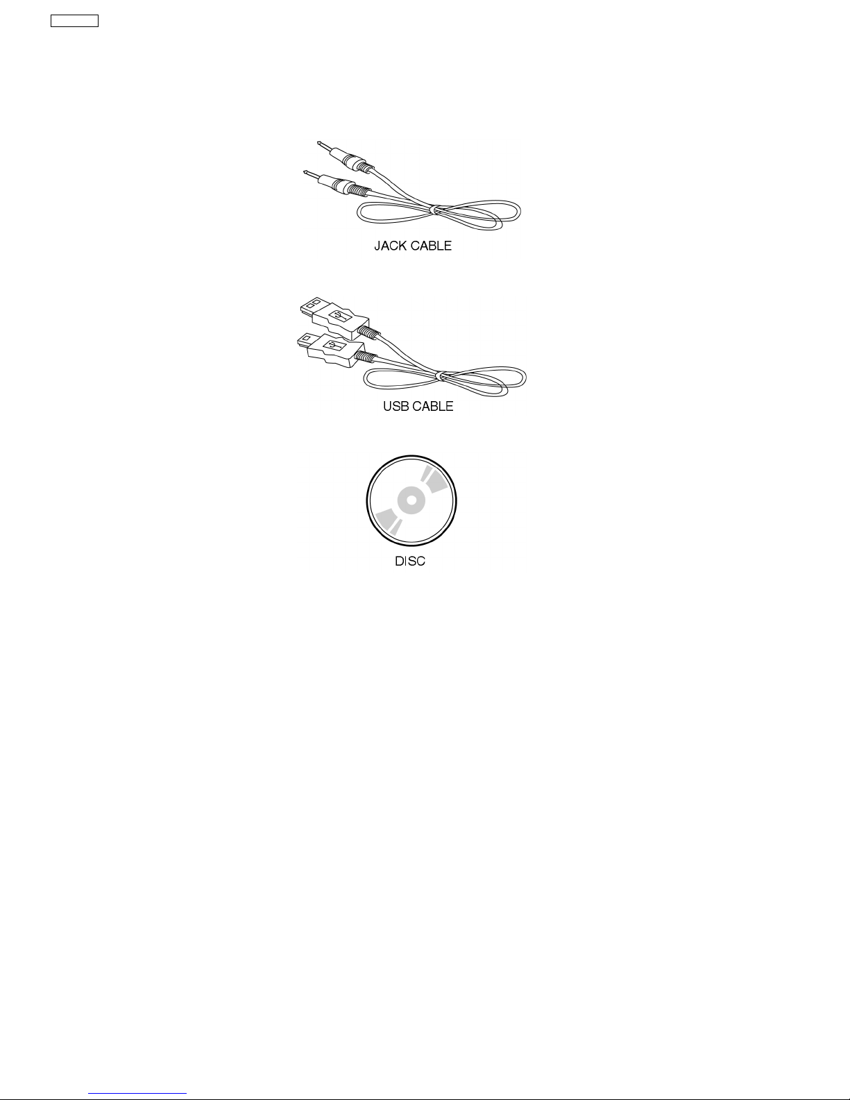
2 Accessories
Note : Refer to Packing Materials & Accessories Parts List (Section 6) for the part number.
4
RR-US475E
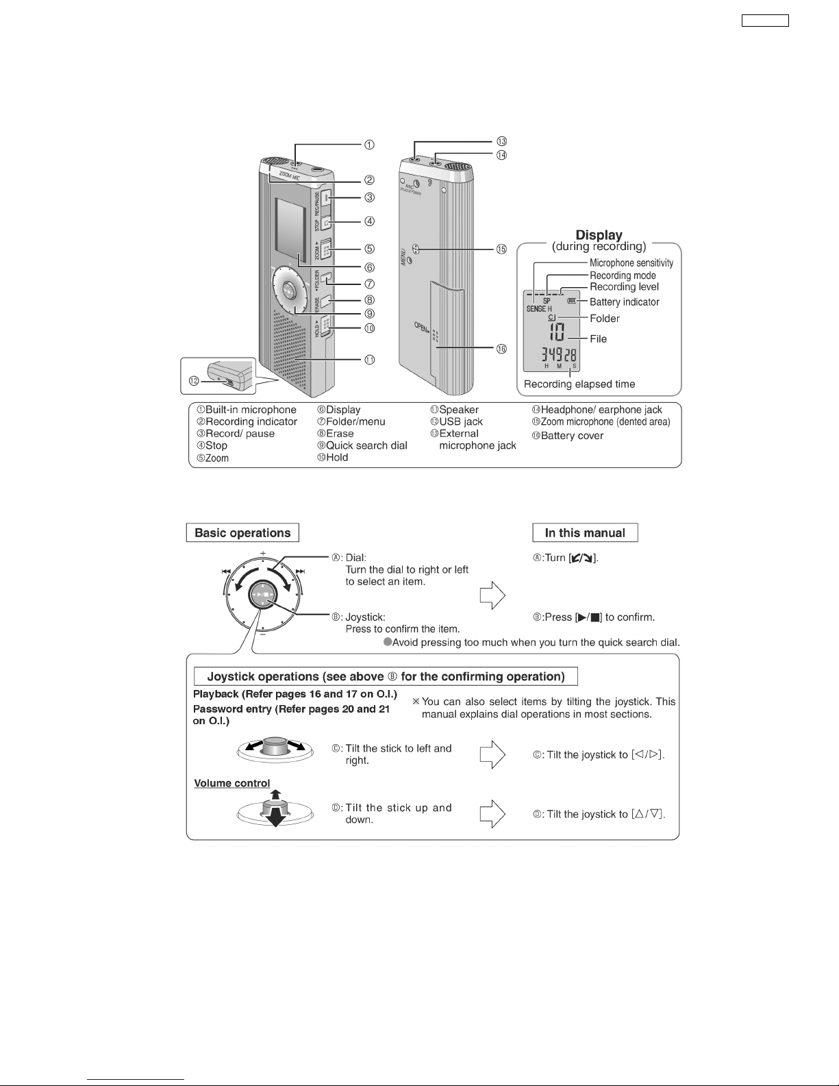
3 Operating Procedures
3.1. Components of IC Recorder
3.1.1. Basic control operation on Quick Search Dial
5
RR-US475E
3.2. Test Mode
3.2.1. Operation Check Mode
This unit is equipped with the functions to check it to record or playback usually, the display of LCD and USB connection.
Caution!
When the checking operation is performed, all recorded data will be cleared.
Note:
· When there are no available items of any track, the unit can not be operated to check it to record and playback.
To continue record and playback check, erase unneeded items.
· For operation check mode, external microphone(not included), earphone(not included), USB cable(included), AC
adaptor(included), and compu ter are necessary.
Note:
−
− −
− You can use a conden ser microphone without a built-in power supply. Plug type: 3.5mm (1/8in) monaural.
−
− −
− Hearphone: Plug type; 3.5mm (1/8in) monau ral.
3.2.2. To Enter into test mode
1. Set to [HOLD] mode.
2. Installed batteries into unit.
3. Press & hold down the [ERASE] switch, follow by the [STOP] switch & [REW] button.
Note:
The item 3 shown above should be operate within 3 seconds.
4. After all segment of LCD Lights up, the unit is entered to Operation Check Mode. During the Operation Check Mode, the
Recording LED is blinking.
5. To cancel test mode, power off the unit by remove batteries
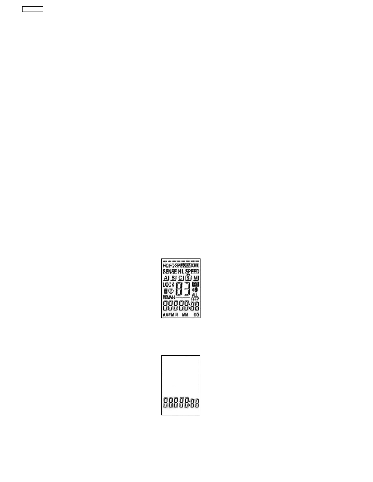
3.2.3. Test Mode
Note:
The LCD indications shown below are examples of test mode with the folder A and no recording data.
1. Enter into test mode, check all segment of LCD lights up.
Fig. 1
· RECORDING INDICATOR: Flashing
2. Release the HOLD mode, by sliding [HOLD] switch down.
3. Check the display of LCD is displayed as shown below.
Fig.2
· RECORDING INDICATOR: Flashing
4. Rotate the jog to the right [JOG +]
5. Check the display of LCD is displayed as shown below.
6
RR-US475E
 Loading...