

Page 1
ORDER NO. MD0706008SE
FM Radio/DAB-FM Radio
RF-U300EG
RF-U350EG
RF-D5EB
RF-D7EB
Colour
(K) .... Black Type (For RF-U300EG & RF-D5EB only)
(S) .... Silver Type (For RF-U350EG & RF-D7EB only)
Subject :
Please use this supplement manual together with the service manual for Model No. [RF-U300EG-K, Order
No. MD0704062CE], [RF-U350EG-S, Order No. MD0704063CE] , [RF-D5EB-K, Order No. MD0704060CE] and
[RF-D7EB-S, Order No. MD0704061CE].
Measurement and Adjustment (Additional)
CONTENTS
Page Page
1 Measurement and Adjustment 2
1.1. Instrument and Jig to be used
1.2. Preparation for alignment
2
2
1.3. FM alignment 2
1.4. AM alignment
3
© 2007 Matsushita Electric Industrial Co., Ltd. All
rights reserved. Unauthorized copying and
distribution is a violation of law.
Page 2
U300EG / RF-U350EG / RF-D5EB / RF-D7EB
1 Measurement and Adjustment
1.1. Instrument and Jig to be used
• Signal generator
• Oscilloscope and electronic voltmeter
• Headphone jig
• FM dummy antenna
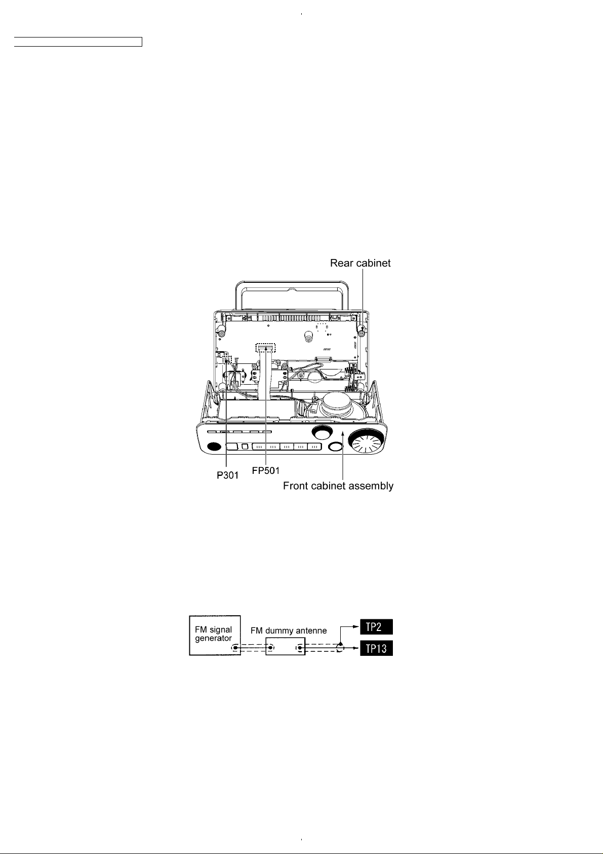
1.2. Preparation for alignment
• Referring to “Disassembly for Front Cabinet Assembly” of “Disassembly and Main Component Replacement Procedures and
Operational Check”, set up the unit.(Fig.1-1)
• Connect the unit to power source (AC 230-240V).
• Set the volume of the unit to Max.
• As for the test points, refer to Print Circuit Board and Schematic Diagram.
Fig.1-1
1.3. FM alignment
1.3.1. FM RF alignment
1. Set the frequency of FM signal generator to 98.0MHz.
2. Input to TP13-TP2 of IC1 through the FM dummy antenna. (see Fig.1-2)
3. Adjust T3 so that the output will be maximized. (see Fig.1-4)
Fig.1-2
1.3.2. FM IF alignment
1. Set the frequency of FM signal generator to 5ch (98.0MHz).
2. Input to pin 5 of IC1 through the FM dummy antenna.
3. Rotate the core of T3 so that the output wave will be the largest (see Fig.1-4)
2
Page 3

1.4. AM alignment
7
1.4.1. AM VCO alignment
1. Set an electronic voltmeter between W51 (+) and W52 (-). (see Fig.1-4)
2. Receive 522kHz by pressing [Preset 1] key.
3. Adjust T2 so that the output will be DC0.8±0.05V.
4. Rotate Turning knob to receive 1494kHz.
5. Check the output is within the range DC4.4 - 5.2V.
1.4.2. AM RF alignment 1
1. Send 495 kHz from signal generator.
2. Connect the headphone jack to measuring equipment. (see Fig.1-3)
Fig.1-3
RF-U300EG / RF-U350EG / RF-D5EB / RF-D
3. Adjust the Tuning knob and receive 459 kHz.
4. Move the winding wire of the ferrite antenna (T2) and tentatively fix it to the position where the output can be maximized. (see
Fig.1-4)
5. Output at pin 25 of IC1.
1.4.3. AM RF alignment 2
1. Send 1494 kHz from a signal generator.
2. Adjust the Tuning knob and receive 1494 kHz.
3. Adjust VC1 so that the output can be maximized.
4. Output at pin27 of IC1.
1.4.4. Completion of AM alignment
• Assemble the unit and complete the alignment.
1.4.5. Alignment point
Fig.1-4
3
FLE0706
 Loading...