

Panasonic PV-GS19PL, PV-GS31PL, PV-GS35PL Service Manual
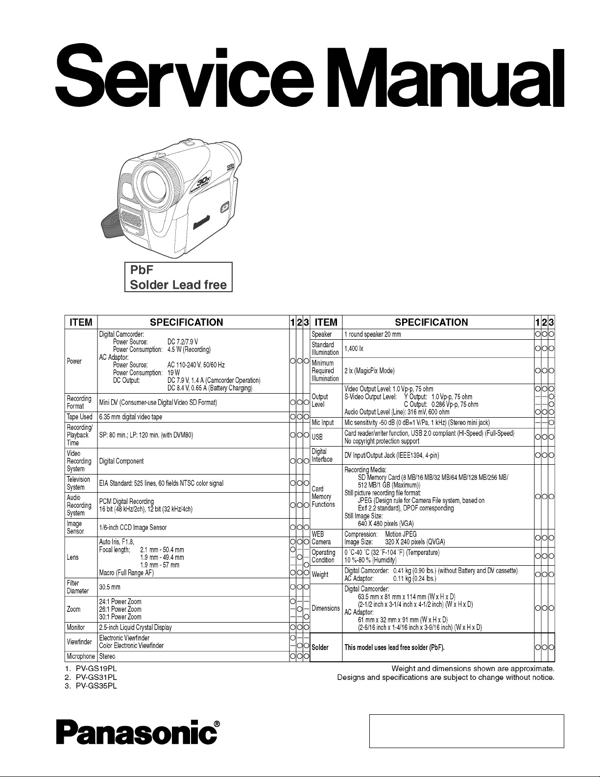
Digital Video Camcorder
PV-GS19PL
PV-GS31PL
PV-GS35PL
Colours
(S)...................Silver Type
ORDER NO. VM0503023CE
© 2005 Matsushita Kotobuki Electronics Industries
LTD. All rights reserved. Unauthorized copying and
distribution is a violation of law.
PV-GS19PL / PV-GS31PL / PV- GS35PL
CONTENTS
Page Page
1 SAFETY PRECAUTIONS 3
2 PREVENTION OF ELECTRO STATIC DISCHARGE (ESD) TO
ELECTROSTATICALLY SENSITIVE (ES) DEVICES
3 ABOUT LEAD FREE SOLDER (PbF)
4 HOW TO REPLACE THE LITHIUM BATTERY
5 HOW TO RECYCLE THE LITHIUM BATTERY
6 SERVICE NOTES (PLEASE READ)
6.1. SERVICE NOTES
7 DISASSEMBLY ASSEMBLY PROCEDURES
7.1. CABINET SECTION
7.2. MECHANISM SECTION
8 ADJUSTMENT PROCEDURES
8.1. SERVICE FIXTURES & TOOLS
8.2. MECHANICAL ADJUSTMENT
8.3. ELECTRICAL ADJUSTMENT
9 SCHEMATIC DIAGRAMS
9.1. SCHEMATIC DIAGRAM & CIRCUIT BOARD LAYOUT
NOTES
9.2. MAIN SCHEMATIC DIAGRAMS
9.3. FRONT SCHEMATIC DIAGRAM
9.4. JACK SCHEMAT IC DIAGRAM
9.5. LCD BACKLIGHT SCHEMATIC DIAGRAM
25
25
44
48
48
50
51
57
57
58
73
74
75
4
5
6
7
8
8
9.6. EVF BACKLIGHT / CASSETTE COVER SCHEMATIC
DIAGRAMS
9.7. CCD / SIDE CASE R / LCD SW SCHEMATIC DIAGRAMS
9.8. INTERCONNECTION SCHEMATIC DIAGRAM
9.9. VOLTAGE CHART
10 CIRCUIT BOARD LAYOUT
10.1. MAIN C.B.A.
10.2. FRONT C.B.A.
10.3. JACK C.B.A.
10.4. LCD BACKLIGHT C.B.A.
11 BLOCK DIAGRAMS
12 EXPLODED VIEWS
12.1. MAIN PARTS SECTION
12.2. FRONT AND BOTTOM CASE SECTION
12.3. SIDE CASE R AND LCD SECTION
12.4. CCD AND LENS SECTION
12.5. EVF SECTION
12.6. MECHANISM SECTION
12.7. PACKING PARTS AND ACCESSORIES SECTION
13 REPLACEMENT PARTS LISTS
13.1. MECHANICAL REPLACEMENT PARTS LIST
13.2. ELECTRICAL REPLACEMENT PARTS LIST
76
77
78
79
83
83
85
86
87
89
101
101
102
103
104
105
106
107
108
108
110
2
1 SAFETY PRECAUTIONS
GENERAL GUIDELINES
1. IMPORTANT SAFETY NOTICE
There are special components used in this equipment
which are important for safety. These parts are marked by
in the Schematic Diagrams, Circuit Board Layout,
Exploded Views and Replacement Parts List. It is essential
that these critical parts should be replaced with
manufacturer’s specified parts to prevent shock, fire, or
other hazards. Do not modify the original design without
permission of manufacturer.
2. An Isolation Transformer should always be used during the
servicing of AC Adaptor whose chassis is not isolated from
the AC power line. Use a transformer of adequate power
rating as this protects the technician from accidents
resulting in personal injury from electrical shocks. It will also
protect AC Adaptor from being damaged by accidental
shorting that may occur during servicing.
3. When servicing, observe the original lead dress. If a short
circuit is found, replace all parts which have been
overheated or damaged by the short circuit.
4. After servicing, see to it that all the protective devices such
as insulation barriers, insulation papers shields are properly
installed.
5. After servicing, make the following leakage current checks
to prevent the customer from being exposed to shock
hazards.
PV-GS19PL / PV-GS31PL / PV- GS35PL
A leakage current tester (Simpson Model 228 or equivalent)
may be used to make the hot checks, leakage current must
not exceed 1/2 mA. In case a measurement is outside of
the limits specified, there is a possibility of a shock hazard,
and the equipment should be repaired and rechecked
before it is returned to the customer.
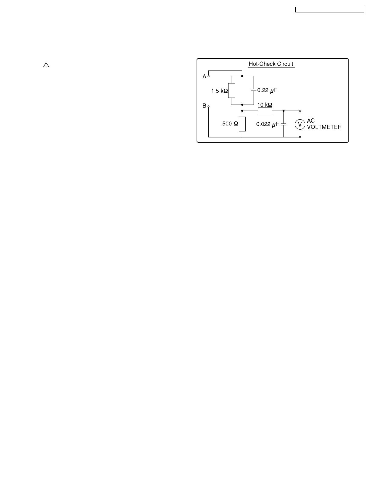
Figure. 1
LEAKAGE CURRENT COLD CHECK
1. Unplug the AC cord and connect a jumper between the two
prongs on the plug.
2. Measure the resistance value, with an ohmmeter, between
the jumpered AC plug and each exposed metallic cabinet
part on the equipment such as screwheads, connectors,
control shafts, etc. When the exposed metallic part has a
return path to the chassis, the reading should be between 1
MΩ and 5.2 MΩ . When the exposed metal does not have a
return path to the chassis, the reading must be infinity.
LEAKAGE CURRENT HOT CHECK
(See Figure 1.)
1. Plug the AC cord directly into the AC outlet. Do not use an
isolation transformer for this check.
2. Connect "A" to exposed metallic part on the set. And
connect "B" to a good earth ground, as shown in Figure 1.
3. Use an AC voltmeter, with 1 kΩ/V or more sensitivity, to
measure the potential across the resistor.
4. Check each exposed metallic part, and measure the
voltage at each point.
5. Reverse the AC plug in the AC outlet and repeat each of the
above measurements.
6. The potent ial at any point should not exceed 0.25 V RMS.
3

PV-GS19PL / PV-GS31PL / PV- GS35PL
2 PREVENTION OF
ELECTRO STATIC
DISCHARGE (ESD) TO
ELECTROSTATICALLY
SENSITIVE (ES) DEVICES
Some semiconductor (solid state) devices can be damaged
easily by static electricity. Such components commonly are
called Electrostatically Sensitive (ES) Devices. Examples of
typical ES devices are integrated circuits and some field-effect
transistors and semiconductor "chip" components. The
following techniques should be used to help reduce the
incidence of component damage caused by electro static
discharge (ESD).
1. Immediately before handling any semiconductor
component or semiconductor-equipped assembly, drain off
any ESD on your body by touching a known earth ground.
Alternatively, obtain and wear a commercially available
discharging ESD wrist strap, which should be removed for
potential shock reasons prior to applying power to the unit
under test.
2. After removing an electrical assembly equipped with ES
devices, place the assembly on a conductive surface such
as aluminum foil, to prevent electrostatic charge buildup or
exposure of the assembly.
3. Use only a grounded-tip soldering iron to solder or unsolder
ES devices.
4. Use only an antistatic solder removal device. Some solder
removal devices not classified as "antistatic (ESD
protected)" can generate electrical charge sufficie nt to
damage ES devices.
5. Do not use freon-propelled chemicals. These can generate
electrical charges sufficie nt to damage ES devices.
6. Do not remove a replacement ES device from its protective
package until immediately before you are ready to install it.
(Most replacement ES devices are packaged with leads
electrically shorted together by conductive foam, aluminum
foil or comparable conduc tive material).
7. Immediately before removing the protective material from
the leads of a replacement ES device, touch the protective
material to the chassis or circuit assembly into which the
device will be installed.
CAUTION :
Be sure no power is applied to the chassis or circuit, and
observe all other safety precautions.
8. Minimize bodily motions when handling unpackaged
replacement ES devices. (Otherwise harmless motion such
as the brushing together of your clothes fabric or the lifting
of your foot from a carpeted floor can generate static
electricity (ESD) sufficient to damage an ES device).
4
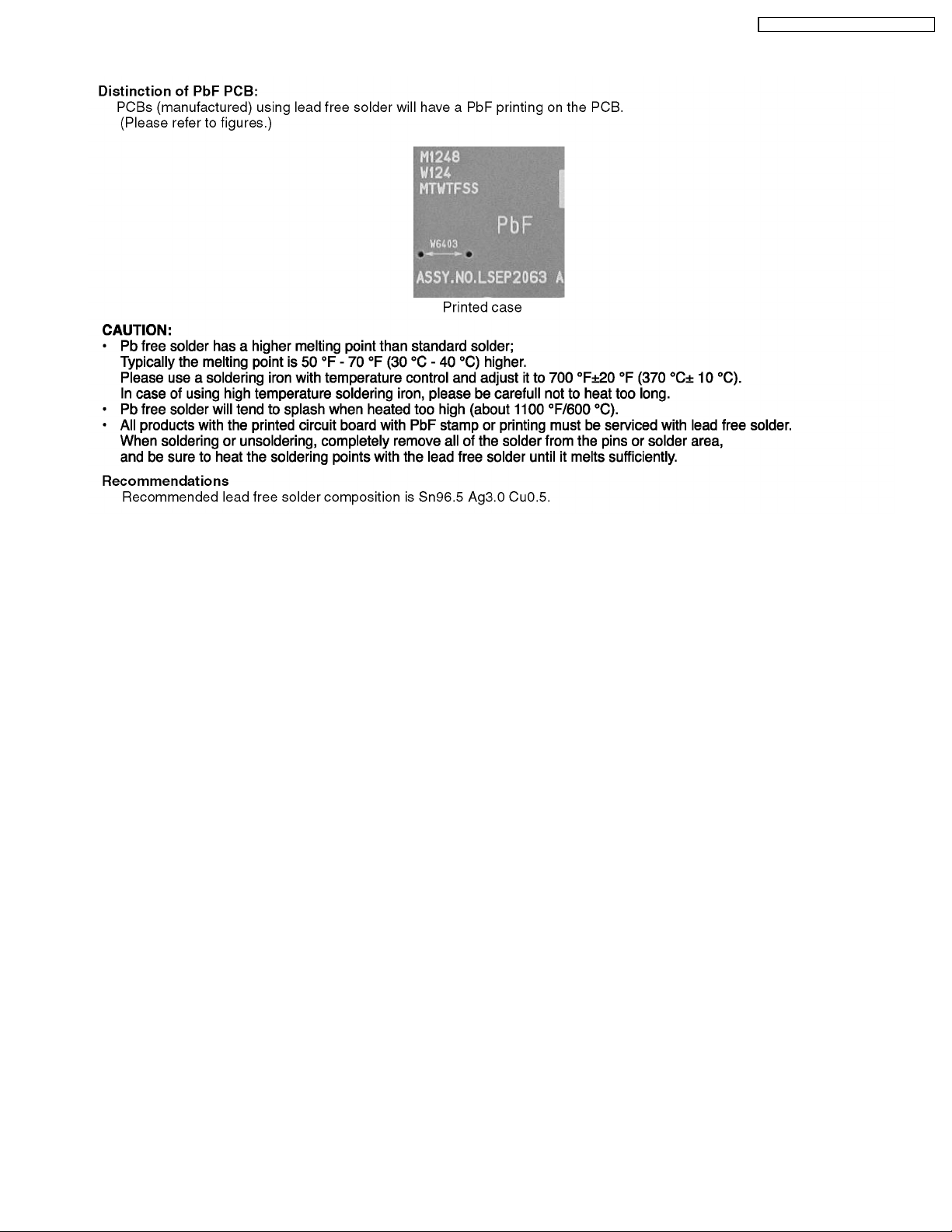
3 ABOUT LEAD FREE SOLDER (PbF)
PV-GS19PL / PV-GS31PL / PV- GS35PL
5
PV-GS19PL / PV-GS31PL / PV- GS35PL
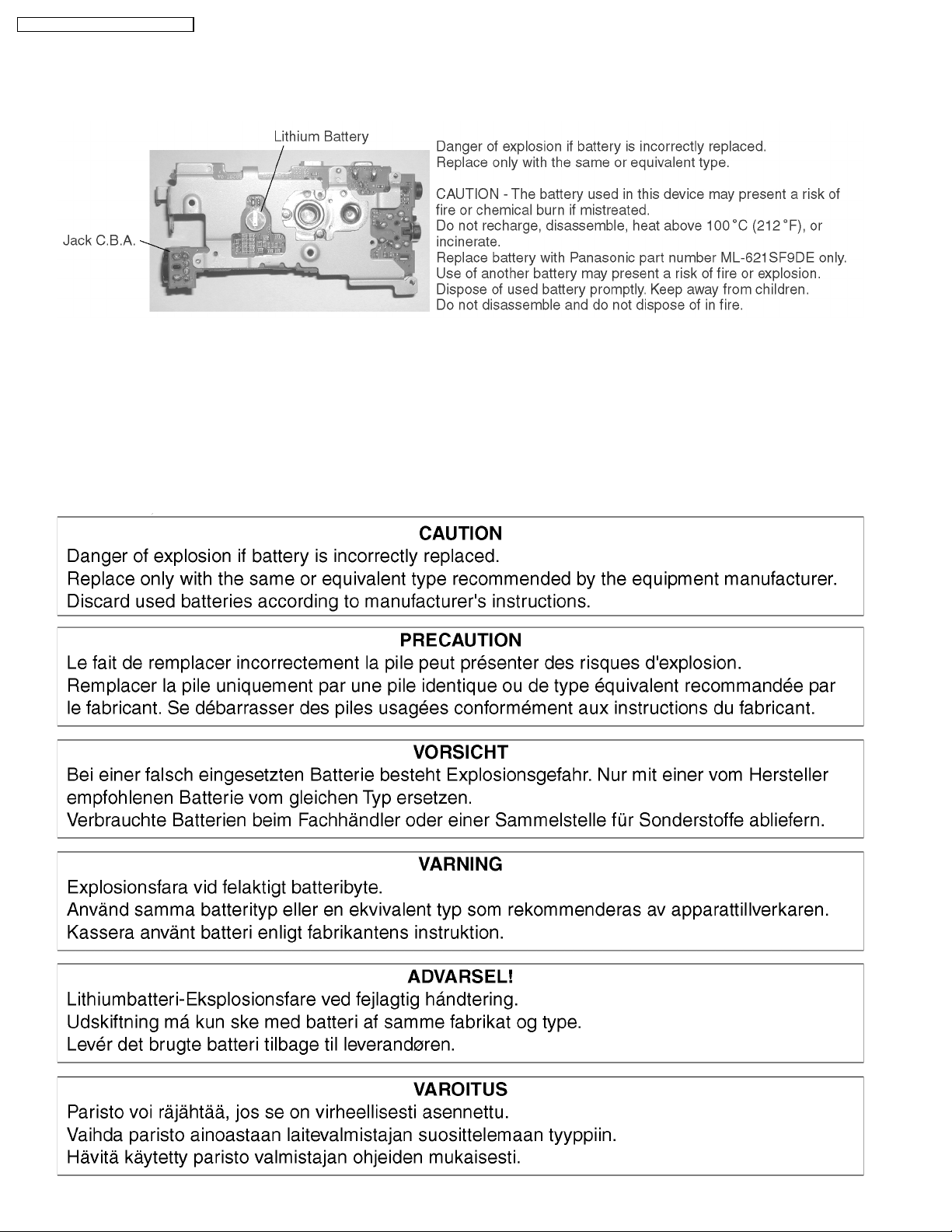
4 HOW TO REPLACE THE LITHIUM BATTERY
Remove the Jack C.B.A. (Refer to “DISASSEMBLY ASSEMBLY PROCEDURES.”)
Unsolder the Lithium Battery “ML-621SF9DE” and then replace the new one.
NOTE:
This Lithium battery is a critical component. (Type No.: ML-621SF9DE Manufactured by Panasonic.)
It must never be subjected to excessive heat or discharge.
It must therefore only be fitted in equipment designed specifically for its use.
Replacement batteries must be of the same type and manufacture.
They must be fitted in the same manner and location as the original battery, with the correct polarity contacts observed.
Do not attempt to re-charge the old battery or re-use it for any other purpose.
It should be disposed of in waste products destined for burial rather than incineration.
6

5 HOW TO RECYCLE THE LITHIUM BATTERY
PV-GS19PL / PV-GS31PL / PV- GS35PL
7
PV-GS19PL / PV-GS31PL / PV- GS35PL
6 SERVICE NOTES (PLEASE READ)
6.1. SERVICE NOTES
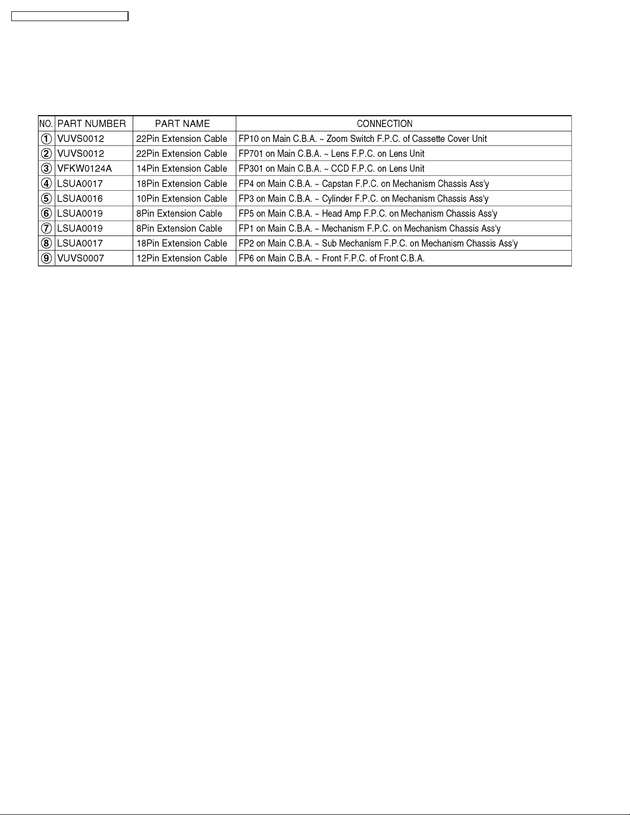
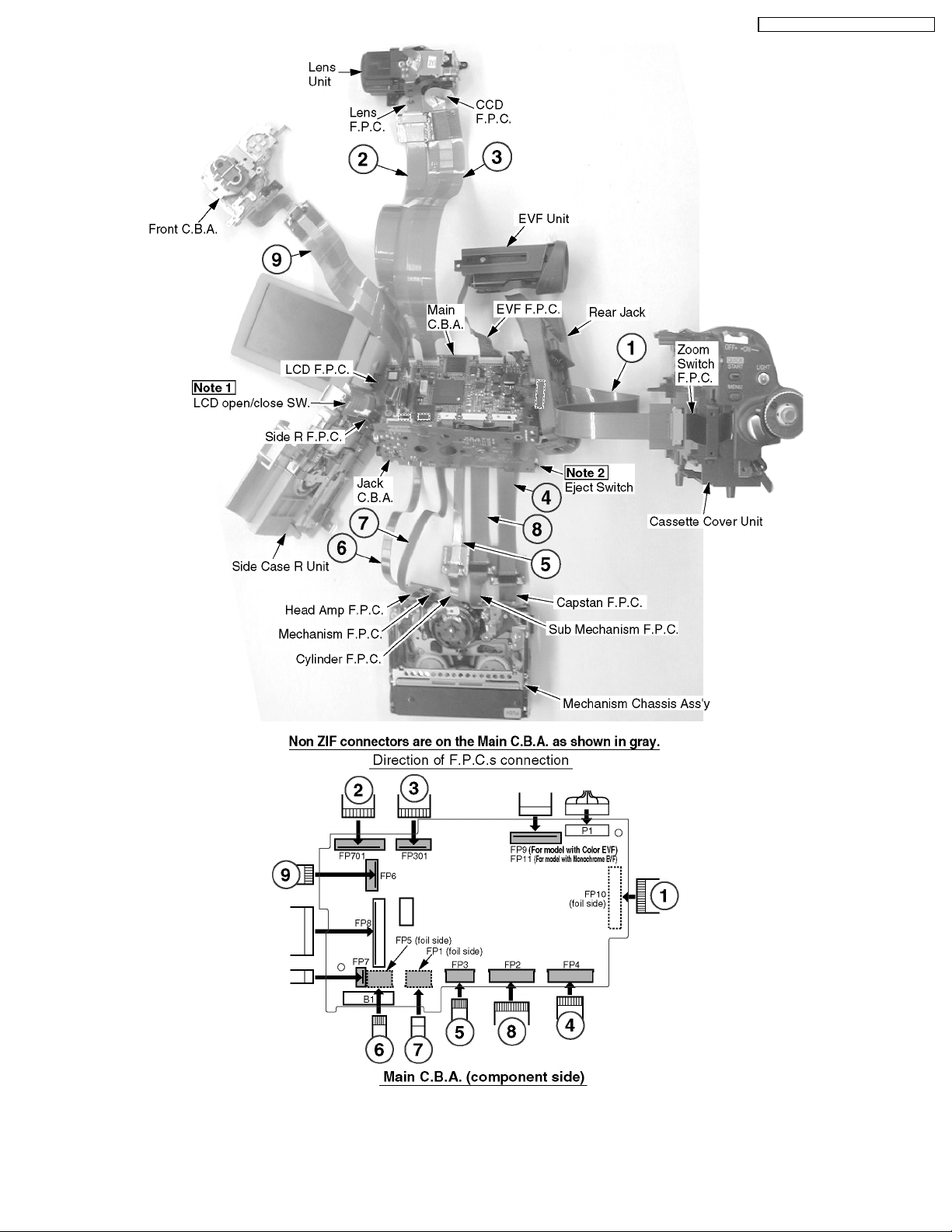
6.1.1. EXTENSION CABLES FOR SERVICE POSITION
Using the following Extension Cables, place the unit as shown for check and service.
Note :
1. The LCD open/close SW. is for changing between LCD Display or EVF Display. When turning on EVF Display, place some
paper or tape, etc. on LCD open/close SW. so that this SW. stays ON.
2. To eject the Mechanism, hold down the Eject Switch on the Jack C.B.A. for a short time.
3. Use a grounded ESD wrist strap while disassembling the Lens portion.
4. Connect the F.P.C.s to the connectors, verifying the direction of F.P.C as shown.
5. Use extreme care when unplugging or plugging in connectors.
8
PV-GS19PL / PV-GS31PL / PV- GS35PL
Fig. 1
9
PV-GS19PL / PV-GS31PL / PV- GS35PL
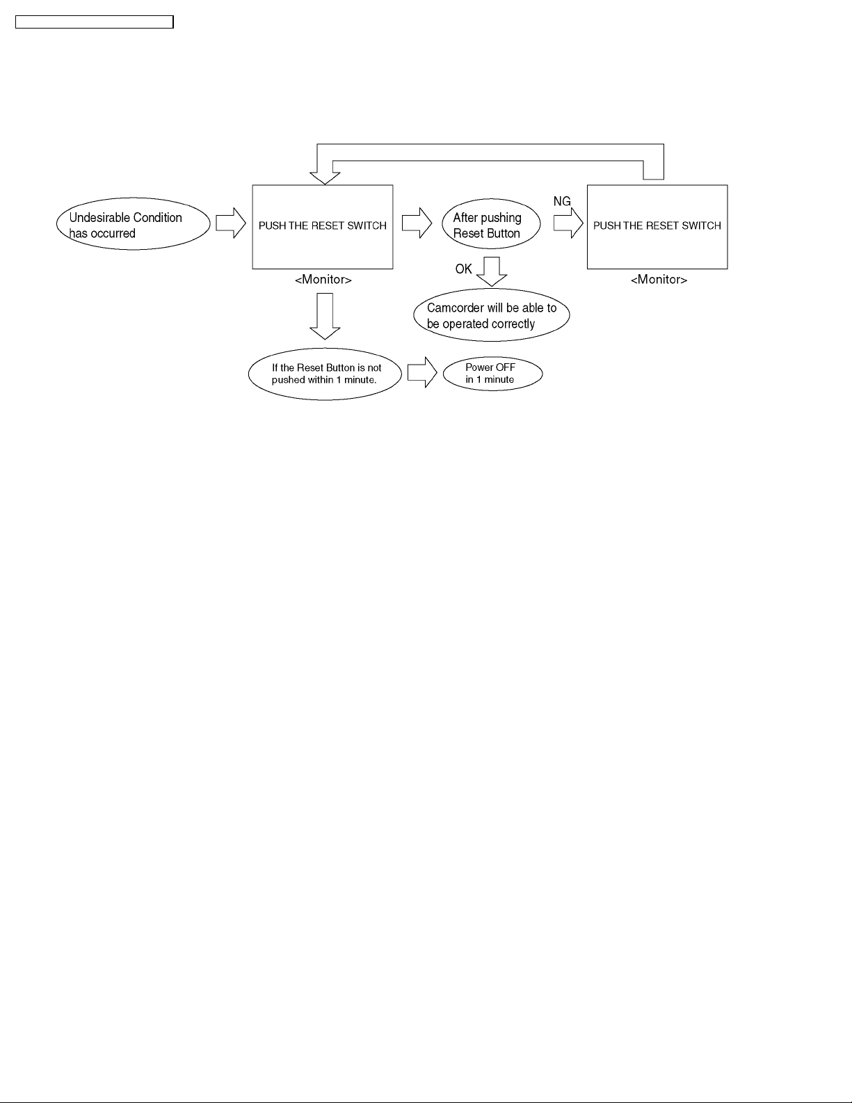
6.1.2. SERVICE MODE
6.1.2.1. ERROR DISPLAY
"PUSH THE RESET SWITC H" is displayed automatically on the EVF or the LCD Monitor when an undesirable condition has
occurred.
Fig. 2
Note:
When "PUSH THE RESET SWITC H" is displayed repeatedly, service is required. Check the Error Code which is listed in the
Service Menu.
6.1.2.2. SERVICE MENU
When abnormal detection contents are confirmed, do the following operation. Automatic diagnosis cord will be displayed.
(Service menu)
To enter the Service Menu
Push the [QUICK START], [JOYSTICK CONTROL LEFT] and [PHOTO SHOT] simultaneously for 3 seconds (with no SD Card
inserted).
Note:
If a tape or SD Card is inserted, the above operation will not work.
This operation displays the following Service Menu items.
· *1 ... Cylinder elapsed time clear.
After replacing the Cylinder Unit, clear the Cylinder elapsed time to 0.
Set to Service Menu.
Press the [JOYSTICK CONTROL UP/DOWN] to select item [8].
Press the [JOYSTICK CONTROL RIGHT] to display [NO/YES] screen.
Press the [JOYSTICK CONTROL UP/DOWN] to select [YES].
Press the [JOYSTICK CONTROL CENTER] button.
· *2 ... Cylinder elapsed time
This item displays the Cylinder elapsed time (in Base 16).
Set to Service Menu.
Press the [JOYSTICK CONTROL UP/DOWN] to select item [3].
Press the [JOYSTICK CONTROL RIGHT] to display [OFF/ON] screen.
Press the [JOYSTICK CONTROL UP/DOWN] to select [ON].
Press the [JOYSTICK CONTROL CENTER] button.
10
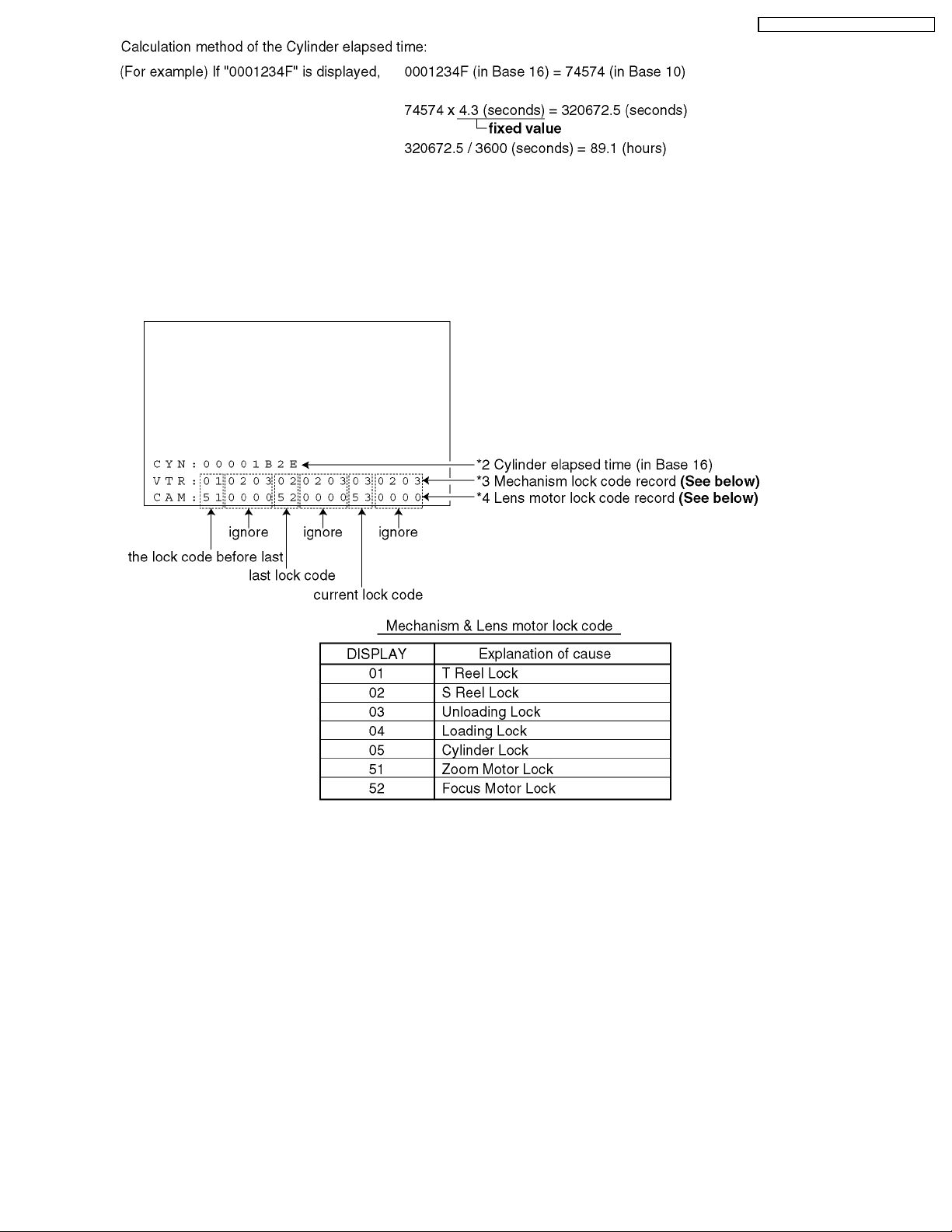
· *3 ... Mechanism lock code record
The current lock code, the last lock code and the lock code before last are displayed in the Item [3] screen.
· *4 ... Lens motor lock code record
The current lock code, the last lock code and the lock code before last are displayed in the Item [3] screen.
Cylinder elapsed time and lock code (Item [3] screen)
PV-GS19PL / PV-GS31PL / PV- GS35PL
Fig. 3
To exit the Service Menu
Unplug the AC Cord.
CLEAR METHOD
If a Card or Tape is inserted, remove before Service Mode operation.
To place the mode dial of this machine into PC connection mode, push the [QUICK START], [JOYSTICK CONTROL LEFT] and
[RECORDING START /STOP] simultaneously for 3 seconds.
Note:
Only perform items 3 and 8 of items 1~8 in the Service Menu.
11

PV-GS19PL / PV-GS31PL / PV- GS35PL
6.1.3. REMOVAL/INSTALLATION OF
F.P.C. FROM NON ZIF (Zero
Insertion Force) CONNECTOR
Removal/Installation of F.P.C. from the Non ZIF (Zero
Insertion Force) connector:
1. The Non ZIF connectors and the ZIF connectors are used
on the unit. And there are 2 types (Type A, Type B) of Non
ZIF connec tors.
2. To remove the F.P.C. from the Non ZIF connector, use the
Plier for Non ZIF Connector (LSVQ0028) to pull out the
F.P.C. as shown. The same Plier for Non ZIF Connector
(LSVQ0028) should also be used to install the F.P.C. to the
Non ZIF Connector.
Fig. 4-2
6.1.4. METHOD FOR
LOADING/UNLOADING OF
MECHANISM
CAUTION:
If loading does not start after DC Power Supply is applied,
DO NOT continue to apply DC Power.
Apply +3 VDC Power Supply to the Loading Motor terminals.
Loading:
DC (-) to Portion "a," DC (+) to Portion "b"
Unloading:
DC (+) to Portion "a," DC (-) to Portion "b"
Fig. 4-1
3. Connect the F.P.C.s to the Non ZIF connectors, verifying
the direction of F.P.C as shown.
Fig. 5
12
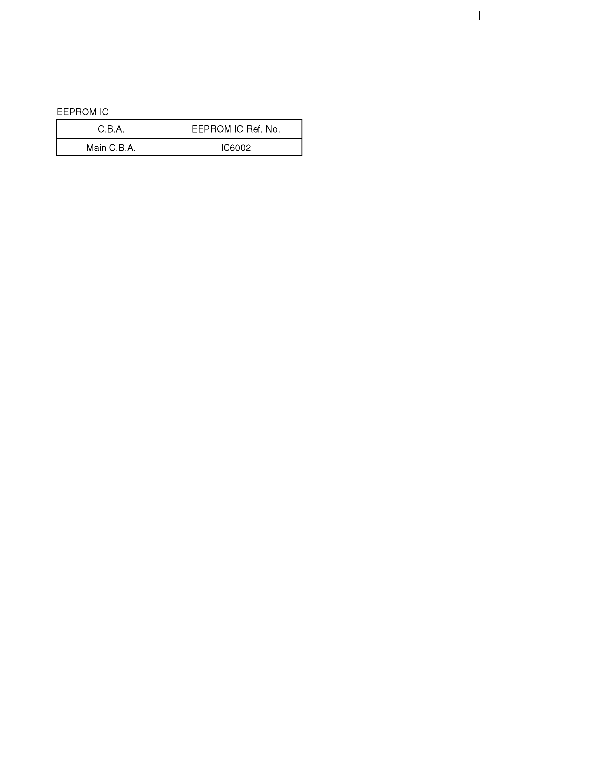
6.1.5. EEPROM DATA
CAUTION:
Be sure to save the EEPROM data using PC-EVR
Adjustment Program before service and adjustment in
order to make sure to avoid an accidental data loss, etc.
using PC-EVR Adjustment Program by first.
PV-GS19PL / PV-GS31PL / PV- GS35PL
13
PV-GS19PL / PV-GS31PL / PV- GS35PL
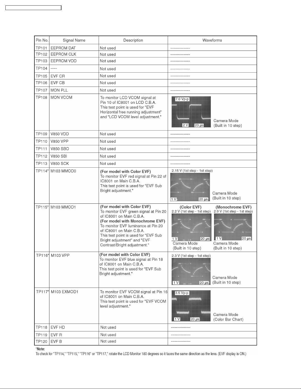
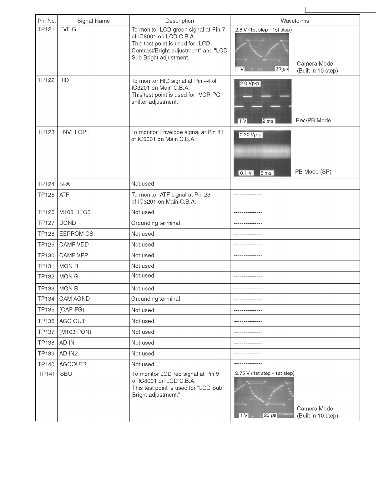
6.1.6. SIGNAL DESCRIPTION ON INTERFACE BOARD FOR ELECTRICAL ADJUSTMENT
(LSUP0007)
A signal check can be performed using the Interface Board.
Fig. 6-1
14
PV-GS19PL / PV-GS31PL / PV- GS35PL
Fig. 6-2
15

PV-GS19PL / PV-GS31PL / PV- GS35PL
Fig. 6-3
16

6.1.7. HOW TO USE THE DVC HEAD CLEANING TAPE / VFK1451
Please use the cleaning tape as described below.
PV-GS19PL / PV-GS31PL / PV- GS35PL
Fig. 7
17

PV-GS19PL / PV-GS31PL / PV- GS35PL
6.1.8. REPLACEMENT PROCEDURES FOR CSP (CHIP SIZE PACKAGE) IC
6.1.8.1. EQUIPMENT
1. Pre-Heater
2. Spot Heater
3. Vacuum Pick-up
4. P.C.B. Holder
Fig. 8-1
Fig. 8-2
18
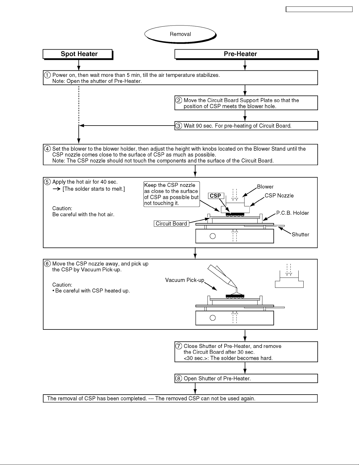
6.1.8.2. REMOVAL OF CSP IC
PV-GS19PL / PV-GS31PL / PV- GS35PL
Fig. 8-3
19

PV-GS19PL / PV-GS31PL / PV- GS35PL
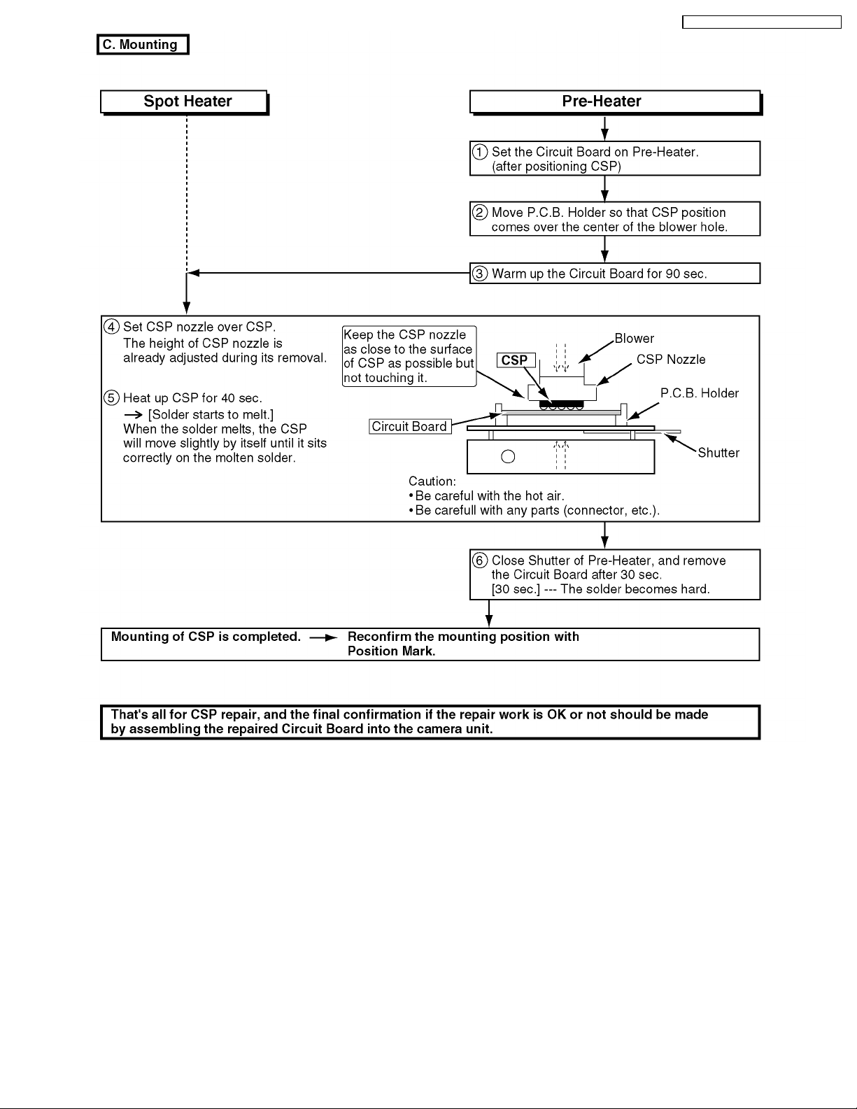
6.1.8.3. INSTALLATION OF CSP IC
Fig. 8-4
20
PV-GS19PL / PV-GS31PL / PV- GS35PL
Fig. 8-5
21
PV-GS19PL / PV-GS31PL / PV- GS35PL
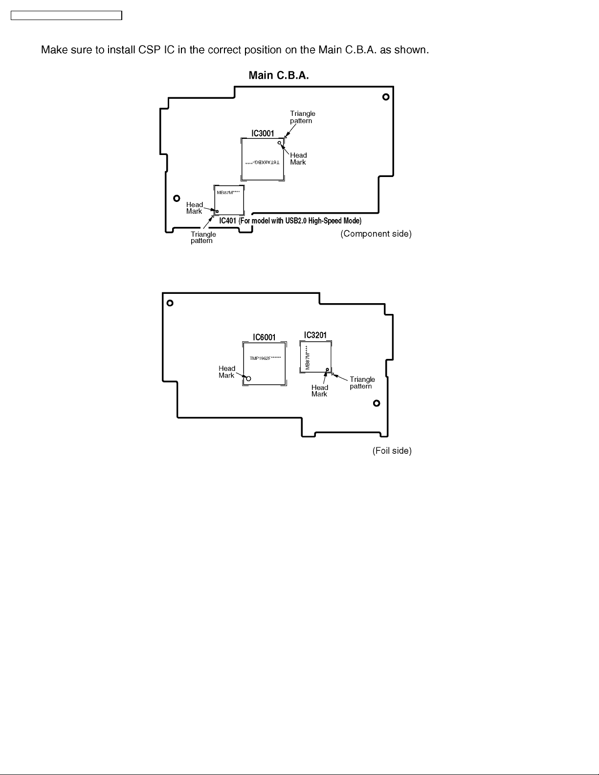
6.1.8.4. CSP IC LOCATION
Fig. 8-6
22

6.1.8.5. TEMPERATURE PROFILE FOR HEAT RESISTANCE OF CSP IC
Refer to the temperature profile. CSP ICs in the 2005 model have the following temperature profile.
PV-GS19PL / PV-GS31PL / PV- GS35PL
Fig. 8-7
23

PV-GS19PL / PV-GS31PL / PV- GS35PL
6.1.9. IC6001 REPLACEMENT NOTE
Two types of IC6001 (FLASH or MASK) are used on a running
change basis, however MASK TYPE of IC6001 is supplied only
as a replacement part.
And MASK TYPE of IC6001 is supplied as IC6001 Kit with
R6022 and R6031.
Perform the addtion (R6022 and R6031) and also deletion
(R6019 and R6032) of the following part simultaneously, when
exchanging from the "FLASH TYPE" to the "MASK TYPE" of
IC6001.
6.1.10. SPECIAL NOTE
All integrated circuits and many other semiconductor devices
are electrostatically sensitive and therefore require the special
handlings techniques described under the
"ELECTROSTATICALLY SENSITIVE (ES) DEVICES" section
of this service manual.
24
7 DISASSEMBLY ASSEMBLY PROCEDURES
7.1. CABINET SECTION
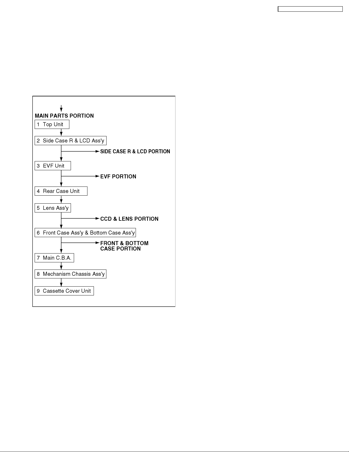
7.1.1. DISASSEMBLY FLOWCHART
This flow chart indicates the disassembly steps of the
cabinet parts and the P.C.Boards in order to gain access to
item (s) to be serviced. When reassembling, perform the
step (s) in the reverse order. Bend, route and dress the
wires as they were originally.
PV-GS19PL / PV-GS31PL / PV- GS35PL
Note :
1. When removing the cabinet, work with care so as not to
break the Locking Tabs.
2. Place a cloth or some other soft material under the P.C.
Boards or Unit to prevent damage.
3. When reinstalling, ensure that the connectors are
connected and electrical components have not been
damaged.
4. Do not supply power to the unit during disassembly and
reassembly.
25
PV-GS19PL / PV-GS31PL / PV- GS35PL
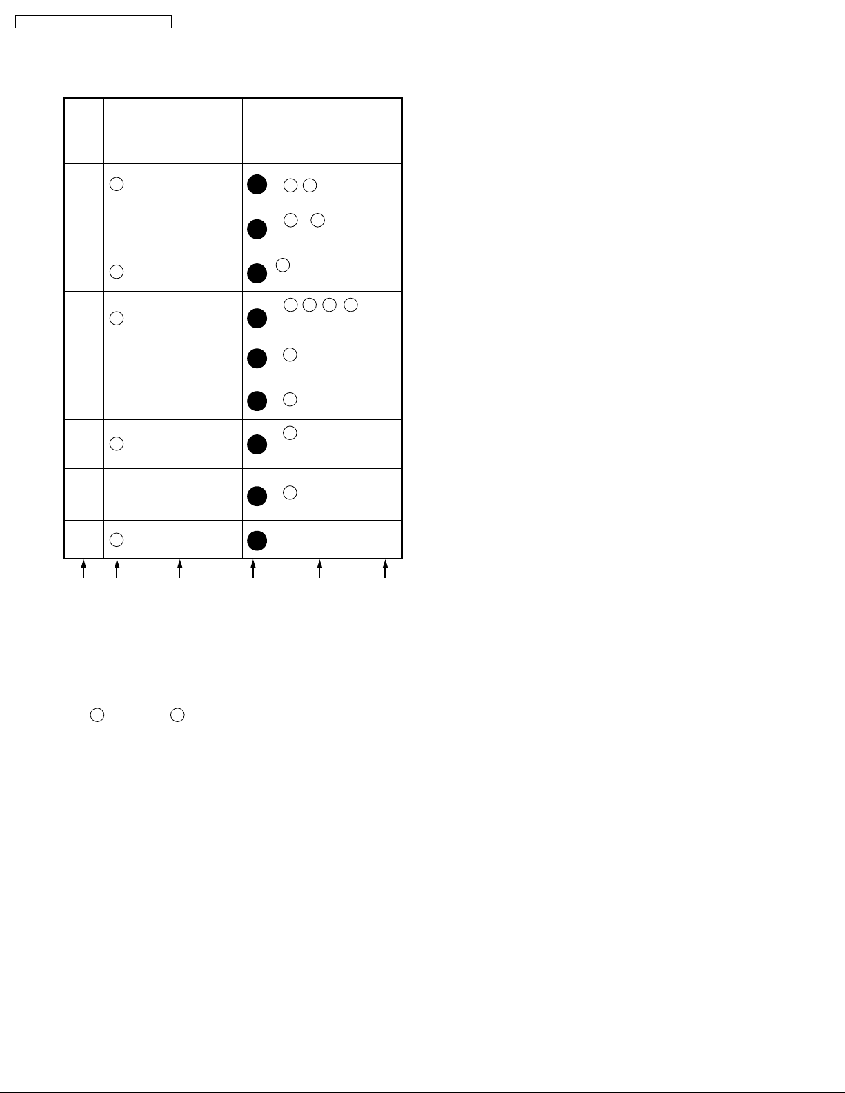
7.1.2. Disassembly Method
MAIN PARTS PORTION
STEP
Ref.
No.
No.
52
1
-2
2
12
3
11
4
5--Lens Ass'y
PART REMOVE
Top Unit
Side Case R &
LCD Ass'y
EVF Unit
Rear Case Unit
Section
No.
433 541
4 ,
1
533450
2 , 4 ,
1
FP7, FP8
533
,
1
1
1
FP11 or FP9
(For model with Color EVF)
450 533 533433
2 , , ,
(For model with S-VIDEO)
P1, (L-1)
533
2 , FP301,
FP701
NOTE
1
3
4
5
6
7
8
9
Front Case Ass'y &
Bottom Case Ass'y
E10
Main C.B.A.
Mechanism
Chassis Ass'y
Cassette Cover
2
Unit
433
3 , FP6, B1
1
450
2 , FP1,FP2,
1
FP3, FP4, FP5,
FP10
413
3
1
-----
1
6
7
8
-
A B C D E F
How to read chart shown above:
A: Order of Procedure steps.
When reassembling, perform steps(s) in reverse order.
B: Ref No.
C: Part to be removed or installed.
D: Section No.
E: Identification of part to be removed, unhooked, unlocked,
released, unplugged, unclamped, or unsoldered.
= 3 Screws , 2(L-1) = 2 Looking Tabs (L-1)
3
404 404
F: Refer to "Notes in chart."
26
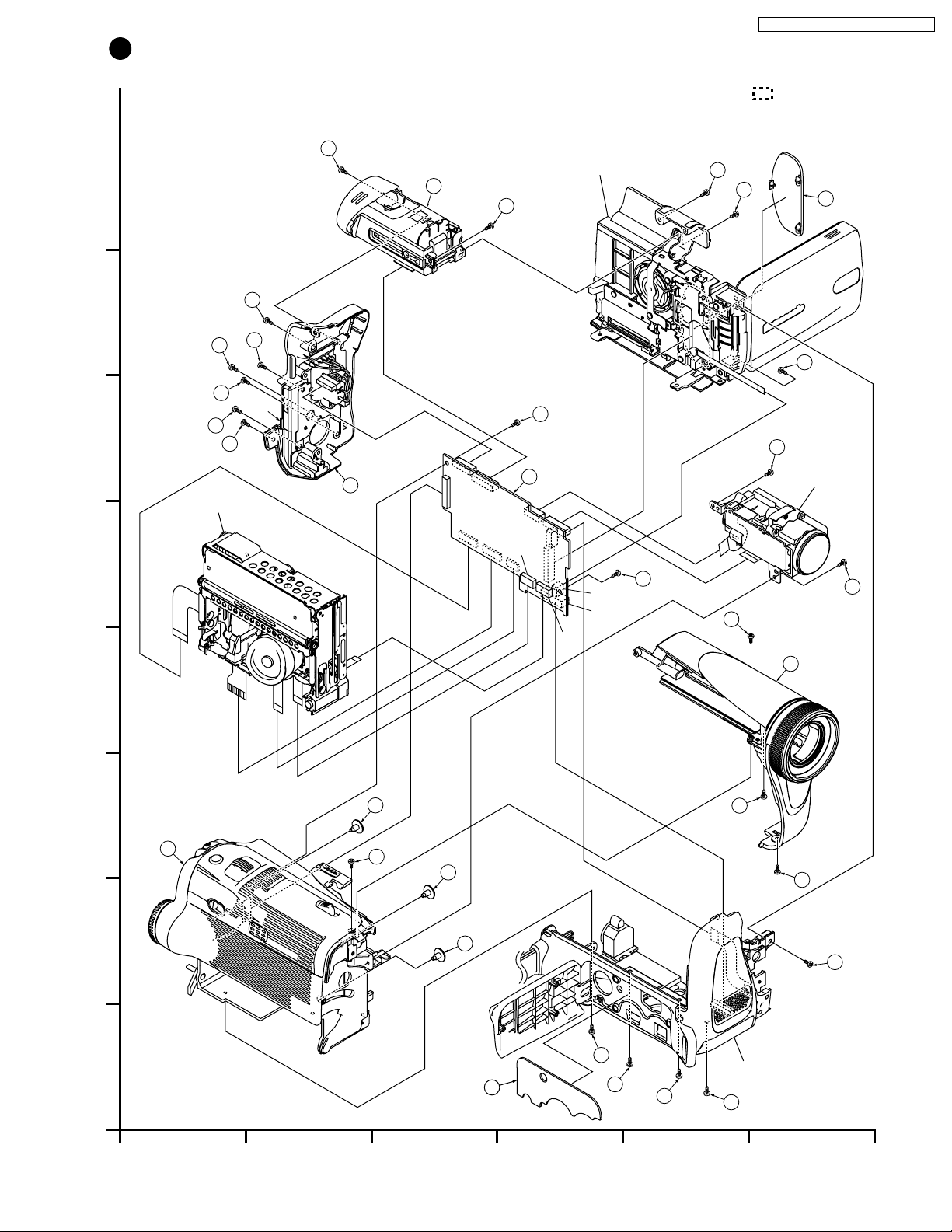
1
MAIN PARTS SECTION
H
433-1
12
533-3
Note:
PV-GS19PL / PV-GS31PL / PV- GS35PL
1. Parts with no Ref. No. in "EXPLODED VIEW" are not supplied.
And some Ref. No. will be skipped. Be sure to make your
orders of replacement parts according to the parts list.
2. The parts indicated by the dotted line are for Ass'y only
and are not supplied.
3. Disregard Ref. No. suffixes when ordering parts. They are used
to describe parts in "Disassembly/Assembly Procedures" section.
Side Case R & LCD Ass'y
533-2
533-2
5
G
F
E
D
433-4
533-4
(PV-GS35PL)
533-4
533-2
(L-1)
450-4
433-4
Mechanism Chassis Ass'y
11
FP10
P1
FP4
FP9 or
FP11
FP2
FP3
E10
FP1
450
-
FP301
FP701
FP6
FP8
7
FP5
FP7
B1
450
433-1
533-5
Lens Ass'y
-
7
533-5
433-1
52
413
-
433-6
8
413
-
8
413
-
8
433
-
6
450
-
4
2
433
-
6
C
2
B
A
1
2 3 4 5 6
541-1
433
-
1
533
-
2
Front Case Ass'y & Bottom Case Ass'y
450
-
2
27

PV-GS19PL / PV-GS31PL / PV- GS35PL
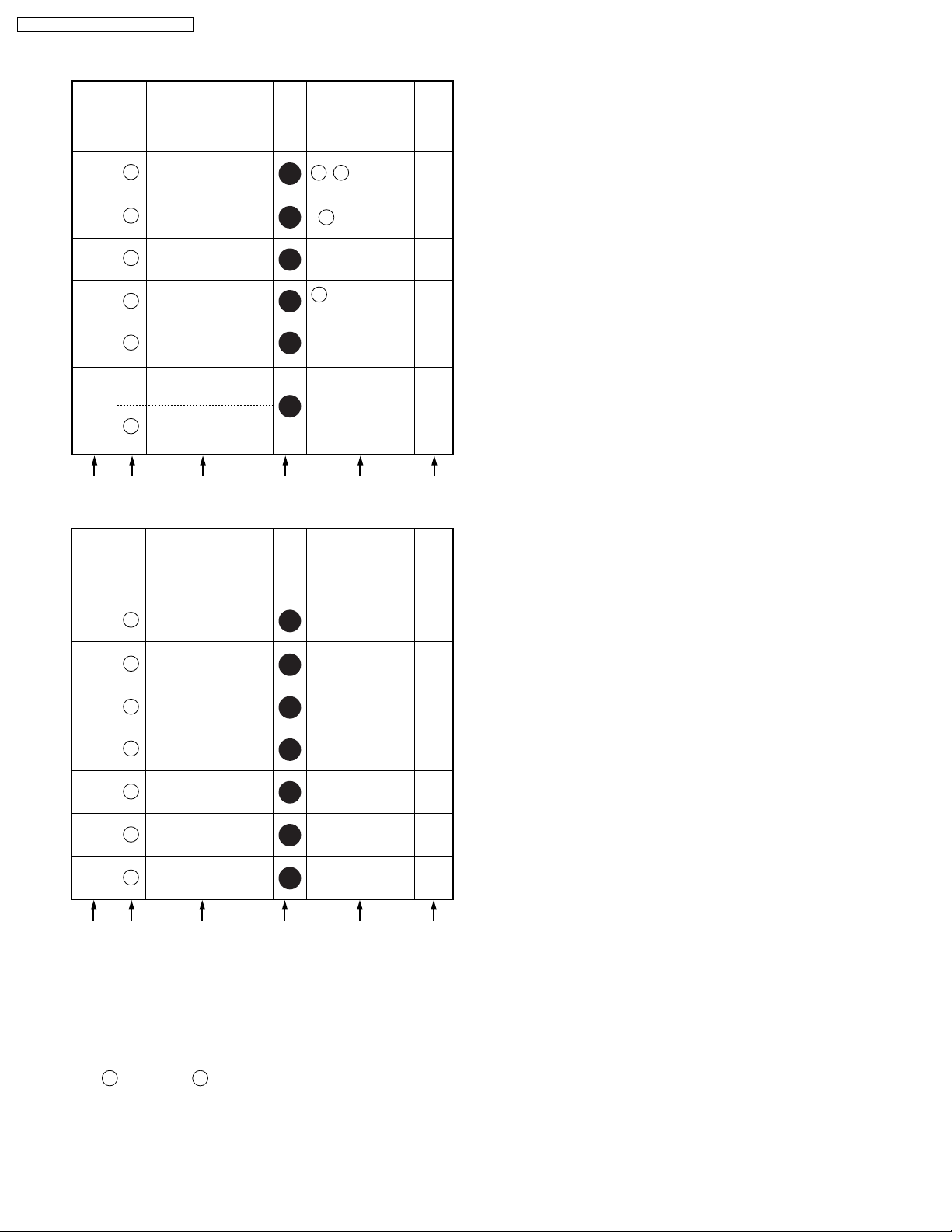
FRONT & BOTTOM CASE PORTION
STEP
Ref.
No.
No.
PART REMOVE
Section
No.
NOTE
-
1
2
Bottom Case Ass'y
E30
Jack C.B.A.
-
Bottom Angle Ass'y
2
2
450433
,
541450
, 2
2
541
-
9
A B C D E F
STEP
No.
Ref.
No.
E20
1
2
56
51
3
PART REMOVE
Front C.B.A.
(For model with Light)
Four Eyes Lens
Front Case
Section
No.
533
4 ,
2
Light Shield Sheet
-----
2
-----
2
2
NOTE
10
10
-
A B C D E F
How to read chart shown above:
A: Order of Procedure steps.
When reassembling, perform steps(s) in reverse order.
B: Ref No.
C: Part to be removed or installed.
D: Section No.
E: Identification of part to be removed, unhooked, unlocked,
released, unplugged, unclamped, or unsoldered.
= 3 Screws , 2(L-1) = 2 Looking Tabs (L-1)
3
404 404
F: Refer to "Notes in chart."
28

2
FRONT AND BOTTOM CASE SECTION
533
E20
PV-GS19PL / PV-GS31PL / PV- GS35PL
Note:
1. Parts with no Ref. No. in "EXPLODED VIEW" are not supplied.
And some Ref. No. will be skipped. Be sure to make your
orders of replacement parts according to the parts list.
2. The parts indicated by the dotted line are for Ass'y only
and are not supplied.
3. Disregard Ref. No. suffixes when ordering parts. They are used
to describe parts in "Disassembly/Assembly Procedures" section.
533
H
57
701
G
533
703
704
(PV-GS35PL)
705
702
(PV-GS31PL, PV-GS35PL)
56
51
708
541
F
533
541
58
711
E
433
60
E30
542
9
59
10
542
D
C
7
541
77
6
541
73
542
543
543
55
75
54
53
Bottom Angle Ass'y
543
76
B
450
71
72
Bottom Case Ass'y
8
A
1
2 3 4 5 6
450
29
PV-GS19PL / PV-GS31PL / PV- GS35PL
SIDE CASE R & LCD PORTION
STEP
Ref.
No.
No.
PART REMOVE
Section
No.
NOTE
31
1
2
3
4
5
6
Side Case R Unit
33
LCD Case A Unit
32
Shaft Case Unit
LCD Backlight
E40
C.B.A.
34
LCD Case B
LCD Panel Ass'y
LCD Shield Case
35
Unit
,
419 457
3
2 , 8(L-1)
455
3
FP8101
3
, (L-2),
542
3
FP8102
4(L-3)
3
3(L-4)
3
A B C D E F
STEP
No.
Ref.
No.
42
1
PART REMOVE
LCD Panel
Section
No.
3
-----
11
-
11
12
12
12
NOTE
13
39
2
3
4
5
6
7
Reflect Sheet
37
Lead Light Panel
38
Diffusion Sheet
40
BEF Sheet
41
BEF Sheet A
36
Panel Holder Unit
(L-5)
3
-----
3
-----
3
-----
3
-----
3
-----
3
13
13
13
13
13
13
A B C D E F
How to read chart shown above:
A: Order of Procedure steps.
When reassembling, perform steps(s) in reverse order.
B: Ref No.
C: Part to be removed or installed.
D: Section No.
E: Identification of part to be removed, unhooked, unlocked,
released, unplugged, unclamped, or unsoldered.
= 3 Screws , 2(L-1) = 2 Looking Tabs (L-1)
3
404 404
F: Refer to "Notes in chart."
30
 Loading...