

Page 1
Digital Video Camcorder
PV-GS150PP
A-MECHANISM
Color
(S)...... Silver Type
ORDER NO.MKE0501403C1
© 2005 Matsushita Kotobuki Electronics Industries
LTD. All rights reserved. Unauthorized copying and
distribution is a violation of law.
Page 2
PV-GS150PP
CONTENTS
Page Page
1 SERVICE INFORMATION 4
1.1. Service Information Regarding IC2001 of PV-GS150PP
1.2. Service Information Regarding Simultaneous Exchange of
MONITOR C.B.A. and LCD PANEL UNIT of PV-GS150PP
2 INTRODUCTION
2.1. INTRODUCTION
2.2. ABOUT LEAD FREE SOLDER (PbF)
3 SAFETY PRECAUTIONS
3.1. GENERAL GUIDELINES
3.2. LEAKAGE CURRENT COLD CHECK
3.3. LEAKAGE CURRENT HOT CHECK (See Figure. 1)
4 PREVENTION OF ELECTRO STATIC DISCHARGE (ESD) TO
ELECTROSTATICALLY SENSITIVE (ES) DEVICES
5 HOW TO REPLACE THE LITHIUM BATTERY (PROCEDURE)
4
6 HOW TO RECYCLE THE LITHIUM BATTERY
7 ADJUSTMENT PROCEDURES
7.1. DISASSEMBLE FLOW CHART
5
7
7
7
8
8
8
8
9
7.2. DISASSEMBLY PROCEDURES
7.3. DISASSEMBLY PROCEDURES MECHA. UNIT
7.4. DISASSEMBLY PROCEDURES OF CAMERA LENS UNIT
8 SERVICE CAUTION
8.1. HOW TO DISCHARGE THE CAPACITOR ON FRONT
C.B.A.
8.2. EEPROM DATA FOR SPARE PARTS OF THE MAIN
C.B.A.
2
10
11
12
12
13
20
24
25
25
25
Page 3

8.3. SERVICE EXTENSION CABLE FOR ALL C.B.A.
INCLUDED IN MODULE UNIT
8.4. LOCATION FOR CONNECTORS OF THE MAIN C.B.A. &
SUB C.B.A.
8.5. CSP IC LOCATION OF THE MAIN C.B.A. & SUB C.B.A.
8.6. TEMPERATURE PROFILE FOR HEAT RESISTANCE OF
CSP IC
9 ELECTRICAL ADJUSTMENT PROCEDURES
9.1. COMPUTER ASSISTED ADJUSTMENT SYSTEM
<TATSUJIN> ADJUSTMENT.
9.2. SET-UP MANUAL FOR DV-Camcorder.
9.3. SET UP PC-EVR ADJUSTMENT PROGRAM
9.4. INITIAL GUIDELINE
10 MECHANICAL ADJUSTMENT PROCEDURES
10.1. ADJUSTMENT ITEM
10.2. ADJUSTMENT PROCEDURES
11 SERVICE MODE
11.1. ERROR DISPLAY
11.2. SERVICE MENU
12 ABBREVIATIONS
13 BLOCK DIAGRAM
13.1. OVERALL BLOCK DIAGRAM
13.2. CAMERA 1 BLOCK DIAGRAM (SENSOR BLOCK
DIAGRAM)
13.3. CAMERA 2 BLOCK DIAGRAM (PROCESS BLOCK
DIAGRAM)
13.4. LENS DRIVE BLOCK DIAGRAM
13.5. CONTROL 1 BLOCK DIAGRAM
13.6. CONTROL 2 BLOCK DIAGRAM
13.7. VIDEO BLOCK DIAGRAM
13.8. MONITOR BLOCK DIAGRAM
14 SCHEMATIC DIAGRAMS
14.1. INTERCONNECTION SCHEMATIC DIAGRAM
14.2. SIDE (L) FLEX. CARD / CASSETTE COVER
SCHEMATIC DIAGRAM
14.3. LCD HINGE (MONITOR FLEX.) SCHEMATIC DIAGRAM
14.4. REAR OPERATION UNIT SCHEMATIC DIAGRAM
14.5. EVF SCHEMATIC DIAGRAM
14.6. CCD FLEX. CARD SCHEMATIC DIAGRAM
14.7. FRONT SCHEMATIC DIAGRAM
14.8. JACK SCHEMATIC DIAGRAM
14.9. SIDE (R) / LCD DET. SCHEMATIC DIAGRAM
25
14.10. MONITOR SCHEMATIC DIAGRAM
14.11. SUB (SUB CONNECTIO N) SCHEMATIC DIAGRAM
27
14.12. SUB (LCD) SCHEMATI C DIAGRAM
14.13. SUB (LENS DRIVE) SCHEMATI C DIAGRAM
29
14.14. SUB (SUB POW ER) SCHEMATI C DIAGRAM
14.15. SUB (CAMERA) SCHEMATI C DIAGRAM
31
32
14.16. MAIN (MAIN CONNECTIO N) SCHEMATIC DIAGRAM
14.17. MAIN (AVIO ) SCHEMATIC DIAGRAM
14.18. MAIN (VIDEO) SCHEMATI C DIAGRAM
32
32
35
36
37
37
37
39
39
39
41
49
49
14.19. MAIN (POW ER) SCHEMATI C DIAGRAM
14.20. MAIN (CONTROL ) SCHEMATIC DIAGRAM
15 CIRCUIT BOARD ASSEMBLIES
15.1. EVF C.B.A.
15.2. LCD DET C.B.A.
15.3. SIDE (R) C.B.A.
15.4. CCD FLEX. CARD C.B.A.
15.5. FRONT C.B.A.
15.6. JACK C.B.A.
15.7. MONITOR C.B.A.
15.8. SUB C.B.A. (COMPONENT SIDE)
15.9. SUB C.B.A. (FOIL SIDE)
15.10. MAIN C.B.A . (COMPONENT SIDE)
15.11. MAIN C.B.A . (FOIL SIDE)
16 CHECKING POINT OF THE CSP IC
50
16.1. CHECKING POINT TABLE
51
52
53
54
55
56
57
57
16.2. WAVEFORM TABLE (PLAY MODE)
17 EXPLODED VIEWS
17.1. FRAME & CASING SECTION (1)
17.2. FRAME & CASING SECTION (2)
17.3. LCD SECTION
17.4. CAMERA LENS SECTION
17.5. VCR MECHANISM SECTION
17.6. PACKING PARTS & ACCESSORIES SECTION
18 REPLACEMENT PARTS LIST
59
18.1. FRAME & CASING SECTION (1) PARTS LIST
18.2. FRAME & CASING SECTION (2) PARTS LIST
59
59
59
60
61
62
18.3. LCD SECTION PARTS LIST
18.4. CAMERA LENS SECTION PARTS LIST
18.5. VCR MECHANISM SECTION PARTS LIST
18.6. PACKING PARTS & ACCESSORIES SECTION PARTS
LIST
18.7. ELECTRICAL REPLACEMENT PARTS LIST
PV-GS150PP
63
64
65
66
67
68
69
74
77
78
82
84
89
89
89
89
90
91
92
93
94
95
97
98
101
101
114
120
120
121
122
123
124
125
126
126
126
127
127
127
127
127
3
Page 4

PV-GS150PP
1 SERVICE INFORMATION
1.1. Service Information Regarding IC2001 of PV-GS150PP
1.1.1. Overview
· DVC model PV-GS150PP will be manufactured 2 distinctly different IC2001.
· These 2 version of IC2001 will be referred to as IC type “FLASH” and “MASK”.
· Supply of the replacement part asks to cause with only “MASK TYPE”.
1.1.2. How to Distinguish the Types of IC2001
1.1.3. Attention for exchanges the IC2001
· There are not the exchangeability between the “FLASH TYPE” and “MASK TYPE” of IC2001.
· Do the addition (R2031and R2150) and also deletion (R2008 and R2022) of the following part simultaneously, when exchange
to the “MASK TYPE” from the “FLASH TYPE” of IC2001.
· It exchange only IC, in the case that IC2001 is “MASK TYPE”. (The exchange of the chip resistor is not necessary.)
4
Page 5
PV-GS150PP
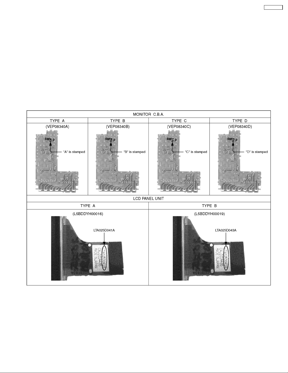
1.2. Service Information Regarding Simultaneous Exchange of MONITOR
C.B.A. and LCD PANEL UNIT of PV-GS150PP
1.2.1. Overview
· DVC model PV-GS150PP will be manufactured 4 distinctly different MONITOR C.B.A. and 2 distinctly different LCD PANEL
UNIT.
· These 4 version of MONITOR C.B.A. will be referred to as C.B.A. type “A”, “B”, “C” and “D”.
· These 2 version of LCD PANEL UNIT will be referred to as UNIT type “A” and “B”.
· There are not the exchangeability between the “A”, “B”, “C” and “D” of MONITOR C.B.A..
· There are not the exchangeability between the “A” and “B” of LCD PANEL UNIT.
· MONITOR C.B.A. and LCD PANEL UNIT supply it the kit.
(Do not supply it in one of each individually MONITOR C.B.A. and LCD PANEL UNIT.)
1.2.2. How to Distinguish the Types of MONITOR C.B.A. and LCD PANEL UNIT
5
Page 6

PV-GS150PP
1.2.3. Difference Comparison Chart
1.2.4. Attention for exchange the MONITOR C.B.A..
· In the case that the LCD PANEL UNIT is TYPE “A”.
Replace the chip resistor of R901 and R910 to the chip resistor that is doing the same pack to the kit.
R901 ERJ3RBD182 ® ERJ3GEY0R00
R910 ERJ3RBD822 ® ERJ3RBD682
· In the case that the LCD PANEL UNIT is TYPE “B”.
Exchange only the MONITOR C.B.A..
1.2.5. Attention for exchange the LCD PANEL UNIT.
· In the case that the MONITOR C.B.A. is TYPE “A” and “B”.
Replace the chip resistor of R901 and R910 to the chip resistor that is doing the same pack to the kit.
R901 ERJ3RBD182 ® ERJ3GEY0R00
R910 ERJ3RBD822 ® ERJ3RBD682
· In the case that the MONITOR C.B.A. is TYPE “C” and “D”.
Exchange only the LCD PANEL UNIT.
CAUTION:
It does the confirmation of the MONITOR C.B.A. and LCD PANEL UNIT without fail on the occasion of the repair and please
do the part exchange.
6
Page 7

PV-GS150PP
2 INTRODUCTION
2.1. INTRODUCTION
This service manual contains technical information which will allow service personnel´s to understand and service this
model.Please place orders using the parts list and not the drawing reference numbers.
If the circuit is changed or modified, this information will be followed by supplement service manual to be filed with original service
manual.
Note 1:
These movie camera uses AC Adaptor is PV-DAC14D
2.2. ABOUT LEAD FREE SOLDER (PbF)
7
Page 8
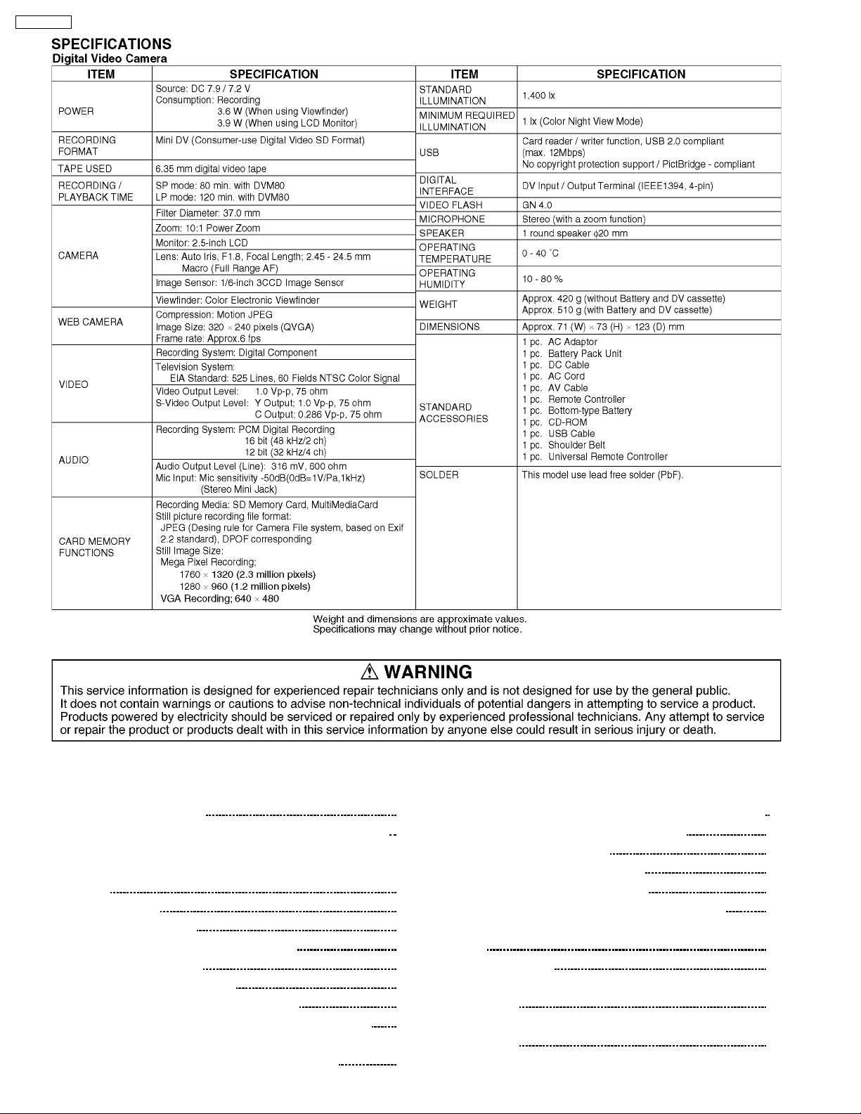
PV-GS150PP
3 SAFETY PRECAUTIONS
3.1. GENERAL GUIDELINES
1. IMPORTANT SAFETY NOTICE
There are special components used in this equipment which are important for safety. These parts are marked by
Schematic Diagrams, Circuit Board Layout, Exploded Views and Replacement Parts List. It is essential that these critical parts
should be replaced with manufacturer’s specified parts to prevent X-RADIATION, shock fire, or other hazards. Do not modify
the original design without permission of manufacturer.
2. An Isolation Transformer should always be used during the servicing of AC Adaptor whose chassis is not isolated from the AC
power line. Use a transformer of adequate power rating as this protects the technician from accidents resulting in personal injury
from electrical shocks. It will also protect AC Adaptor from being damaged by accidental shorting that may occur during
servicing.
3. When servicing, observe the original lead dress. It a short circuit is found, replace all parts which have been overheated or
damaged by the short circuit.
4. After servicing, see to it that all the protective devices such as insulation barriers, insulation papers shields are properly
installed.
5. After servicing, make the following leakage current checks to prevent the customer from being exposed to shock hazards.
3.2. LEAKAGE CURRENT COLD CHECK
1. Unplug the AC cord and connect a jumper between the two prongs on the plug.
2. Measure the resistance value, with an ohmmeter, between the jumpered AC plug and each exposed metallic cabinet part on
the equipment such as screwheads, connectors, control shafts, etc. When the exposed metallic part has a return path to the
chassis, the reading should be between 1MW and 5.2MW. When the exposed metal does not have a return path to the chassis,
the reading must be infinity.
in the
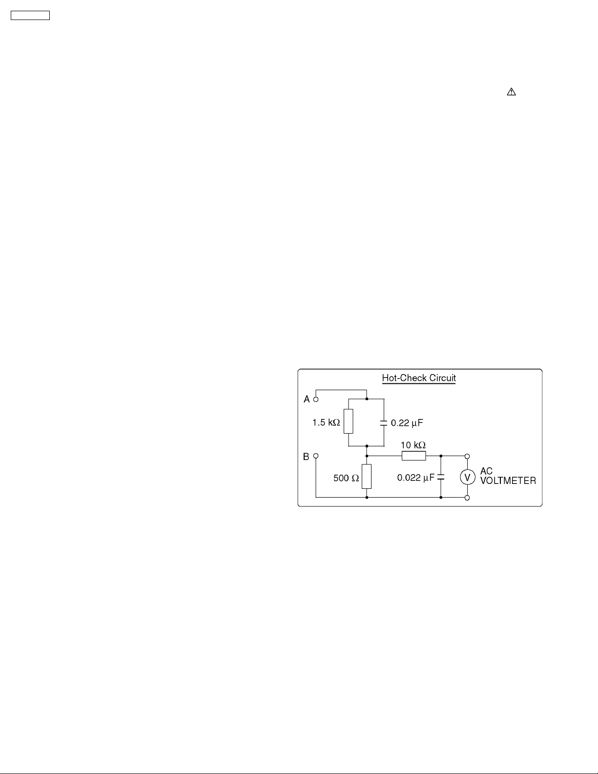
3.3. LEAKAGE CURRENT HOT CHECK (See Figure 1)
1. Plug the AC cord directly into the AC outlet. Do not use an
isolation transformer for this check.
2. Connect “A” to exposed metallic part on the set. And
connect “B” to a good earth ground, as shown in Figure 1.
3. Use an AC voltmeter, with 1 kW/V or more sensitivity, to
measure the potential across the resistor.
4. Check each exposed metallic part, and measure the
voltage at each point.
5. Reverse the AC plug in the AC outlet and repeat each of the
above measurements.
6. The potential at any point should not exceed 0.25 V RMS.
A leakage current tester (Simpson Model 229 or equivalent)
may be used to make the hot checks, leakage current must
not exceed 1/2 mA. In case a measurement is outside of
the limits specified, there is a possibility of a shock hazard,
and the equipment should be repaired and rechecked
before it is returned to the customer.
Figure 1
8
Page 9

PV-GS150PP
4 PREVENTION OF ELECTRO STATIC DISCHARGE (ESD)
TO ELECTROSTATICALLY SENSITIVE (ES) DEVICES
Some semiconductor (solid state) devices can be damaged easily by static electricity. Such components commonly are called
Electrostatically Sensitive (ES) Devices. Examples of typical ES devices are integrated circuits and some field-effect transistors and
semiconductor “chip” components. The following techniques should be used to help reduce the incidence of component damage
caused by electro static discharge (ESD).
1. Immediately before handling any semiconductor component or semiconductor-equipped assembly, drain off any ESD on your
body by touching a known earth ground. Alternatively, obtain and wear a commercially available discharging ESD wrist strap,
which should be removed for potential shock reasons prior to applying power to the unit under test.
2. After removing an electrical assembly equipped with ES devices, place the assembly on a conductive surface such as
aluminum foil, to prevent electrostatic charge buildup or exposure of the assembly.
3. Use only a grounded-tip soldering iron to solder or unsolder ES devices.
4. Use only an antistatic solder removal device. Some solder removal devices not classified as “antistatic (ESD protected)” can
generate electrical charge sufficient to damage ES devices.
5. Do not use freon-propelled chemicals. These can generate electrical charges sufficient to damage ES devices.
6. Do not remove a replacement ES device from its protective package until immediately before you are ready to install it. (Most
replacement ES devices are packaged with leads electrically shorted together by conductive foam, aluminum foil or comparable
conductive material).
7. Immediately before removing the protective material from the leads of a replacement ES device, touch the protective material
to the chassis or circuit assembly into which the device will be installed.
CAUTION:
Be sure no power is applied to the chassis or circuit, and observe all other safety precautions.
8. Minimize bodily motions when handling unpackaged replacement ES devices. (Otherwise harmless motion such as the
brushing together of your clothes fabric or the lifting of your foot from a carpeted floor can generate static electricity (ESD)
sufficient to damage an ES device).
9
Page 10
PV-GS150PP
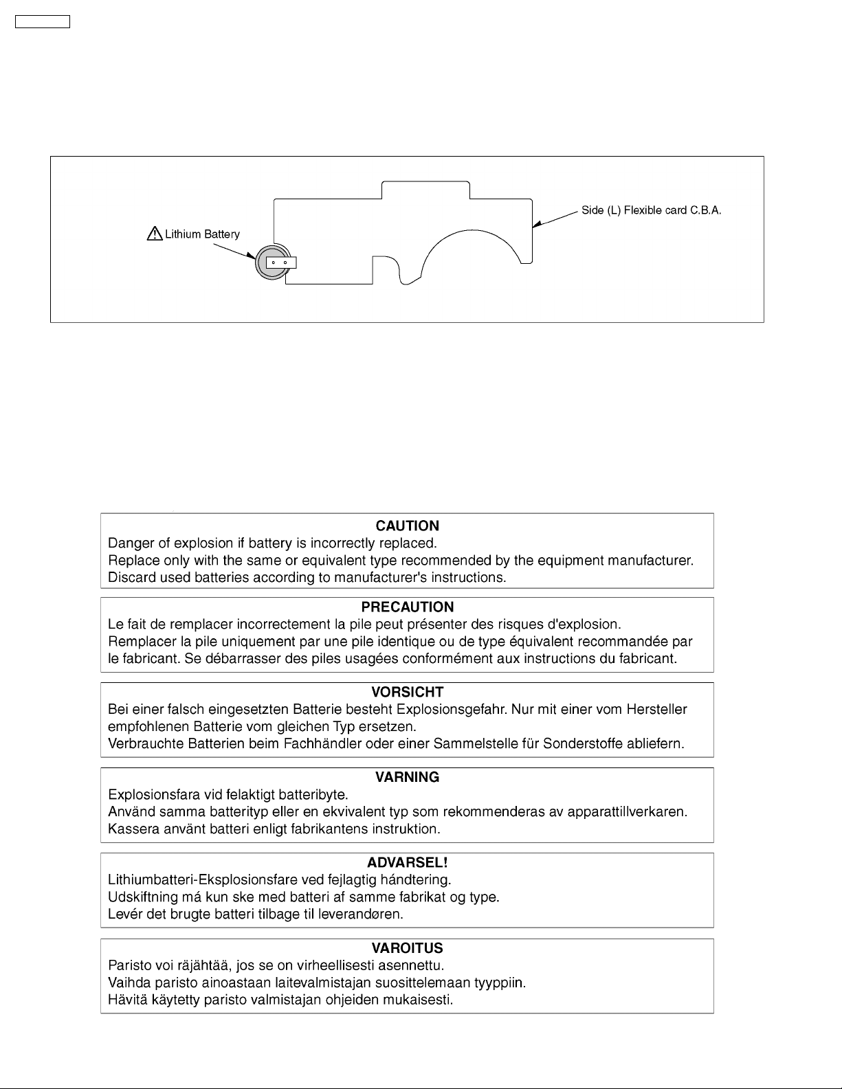
5 HOW TO REPLACE THE LITHIUM BATTERY
(PROCEDURE)
1. Remove the Side Case (L) C.B.A.. (Refer to Disassembly Procedures.)
2. Unsolder the Lithium Battery “ML920S/F9D” and then replace the new one. (See Fig. B1.)
3. Danger of explosion if battery is incorrectly replaced. Replace only with the same or equivalent type.
Fig. B1
Note:
The lithium battery is a critical component. (Type No.: N9ZZ00000297.)
It must never be subjected to excessive heat or discharge.
It must therefore only be fitted in equipment designed specifically for its use.
Replacement batteries must be of the same type and manufacture.
They must be fitted in the same manner and location as the original battery, with the correct polarity contacts observed.
Do not attempt to re-charge the old battery or re-use it for any other purpose.
It should be disposed of in waste products destined for burial rather than incineration.
10
Page 11

6 HOW TO RECYCLE THE LITHIUM BATTERY
PV-GS150PP
11
Page 12
PV-GS150PP
7 ADJUSTMENT PROCEDURES
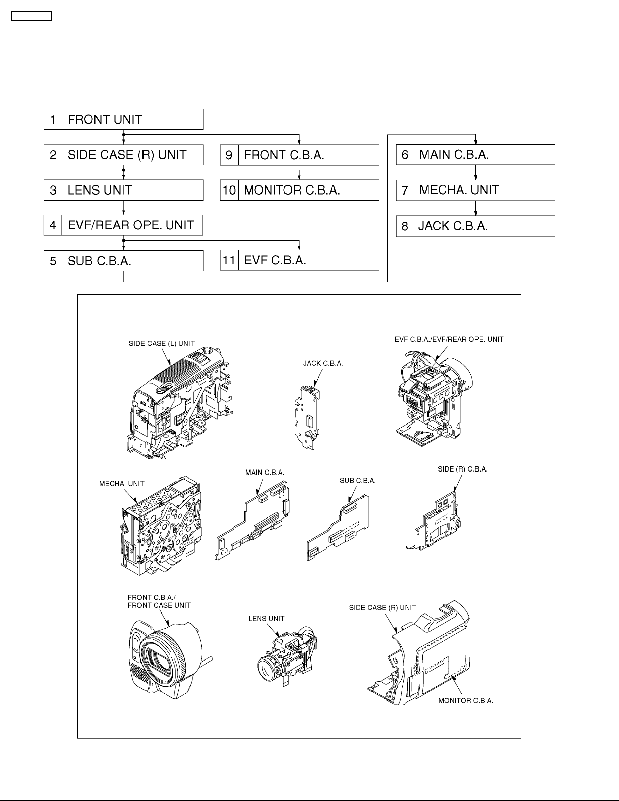
7.1. DISASSEMBLE FLOW CHART
This flow chart indicates the disassembly steps the cabinet parts, C.B.A. and Mecha. Unit in order to access to be serviced. When
reinstalling, perform the steps in the reverse order.
12
Page 13
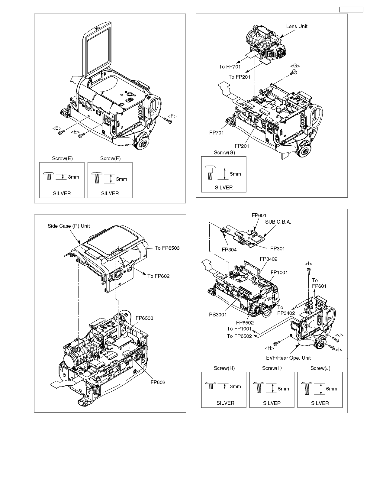
7.2. DISASSEMBLY PROCEDURES
Flow-Chart for Disassembly Procedure
No. Item / Part Fig. Removal (Screw,Connector,Flex. &
1 Front Case
Unit
2 Side Case (R)
Unit
3 Lens Unit Fig. D9 1-Screw (G)
4 EVF/Rear
Operation
Unit,.Sub
C.B.A
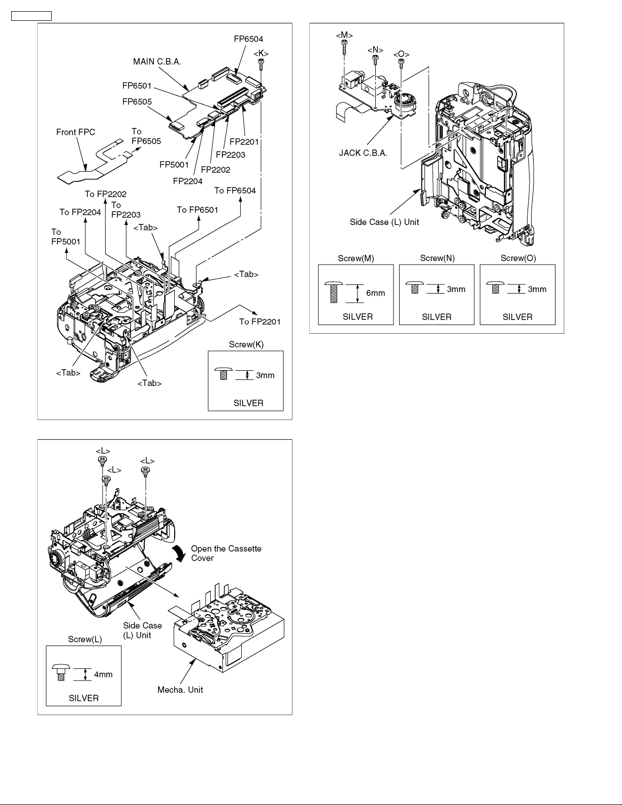
5 Main C.B.A. Fig. D11 8-Connectors FP2201, FP2202,
6 Mecha. Unit Fig. D12 Open the Cassette Cover
7 Jack C.B.A. Fig. D13 1-Screw (M), 1-Screw (N), 1-Screw (O)
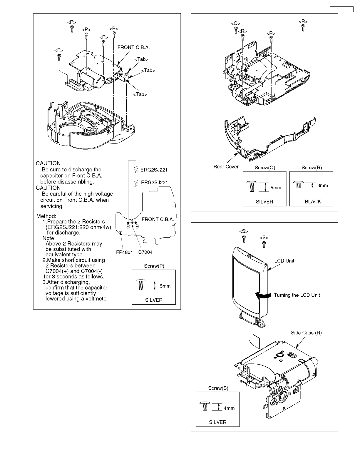
8 Front C.B.A. Fig. D14 5-Screws (P)
9 Monitor C.B.A. Fig. D15 1-Screw (Q), 3-Screws (R)
10 EVF C.B.A. Fig. D20 View ADJ. Unit is Drawn
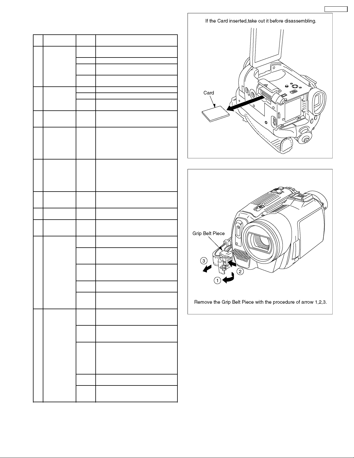
Fig. D2 Remove the Grip Belt Piece with the
procedure of arrow 1,2,3.
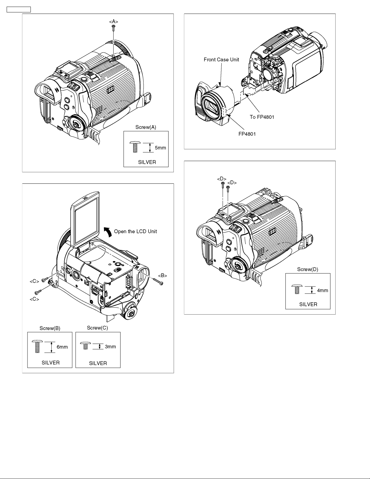
Fig. D3 1-Screw (A)
Fig. D4 Open the LCD Unit
1-Screw (B), 2-Screws (C)
Fig. D5 1-Connector FP4801
Front Case Unit
Fig. D6 2-Screws (D)
Fig. D7 2-Screws (E), 1-Screw (F)
Fig. D8 2-Connectors FP602, FP6503
Side Case (R) Unit
2-Connectors FP201, FP701
Lens Unit
Fig. D10 1-Screw (H), 2-Screws (I), 1-Screw (J)
4-Connectors FP601, FP1001,
FP3402, FP6502
EVF/Rear Operation Unit
2-Connectors FP304, PS3001
Sub C.B.A.
FP2203, FP2204, FP5001,
FP6501,FP6504, FP6505
1-Screw (K)
4-Tabs
Main C.B.A.
3-Screws (L)
Mecha. Unit
Jack C.B.A.
3-Tabs
Front C.B.A.
Rear Cover
Fig. D16 Turning the LCD Unit
2-Screws (S)
LCD Unit
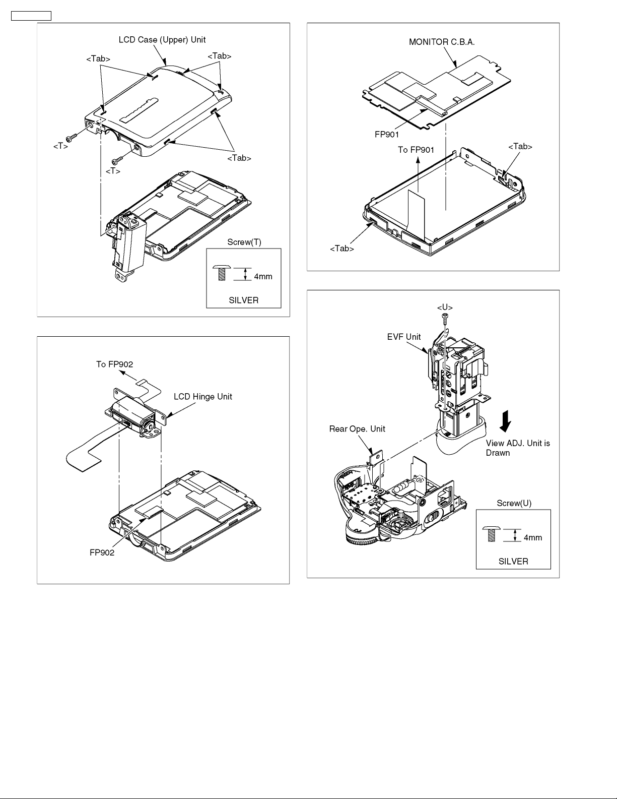
Fig. D17 2-Screws (T)
6-Tabs
LCD Case (Upper) Unit
Fig. D18 1-Connector FP902
LCD Hinge Unit
Fig. D19 1-Connector FP901
2-Tabs
Monitor C.B.A.
1-Screw (U)
Rear Operation Unit
Fig. D21 1-Screw (V)
2-Tabs
EVF Hold Piece
Fig. D22 2-Screws (W)
2-Tabs
View ADJ. Unit
2-Screws (X), 2-Slide Spacers (Y)
1-Connector FP801
EVF LCD Unit
Fig. D23 2-Screws (Z)
EVF Plate / Click Spring
Fig. D24 1-Connector FP802
3-Tabs
EVF C.B.A.
Other)
PV-GS150PP
Fig. D1
Fig. D2
13
Page 14
PV-GS150PP
Fig. D5
Fig. D3
Fig. D4
Fig. D6
14
Page 15
PV-GS150PP
Fig. D7
Fig. D9
Fig. D8
Fig. D10
15
Page 16
PV-GS150PP
Fig. D11
Fig. D13
Fig. D12
16
Page 17
PV-GS150PP
Fig. D14
Fig. D15
17
Fig. D16
Page 18
PV-GS150PP
Fig. D19
Fig. D17
Fig. D18
Fig. D20
18
Page 19
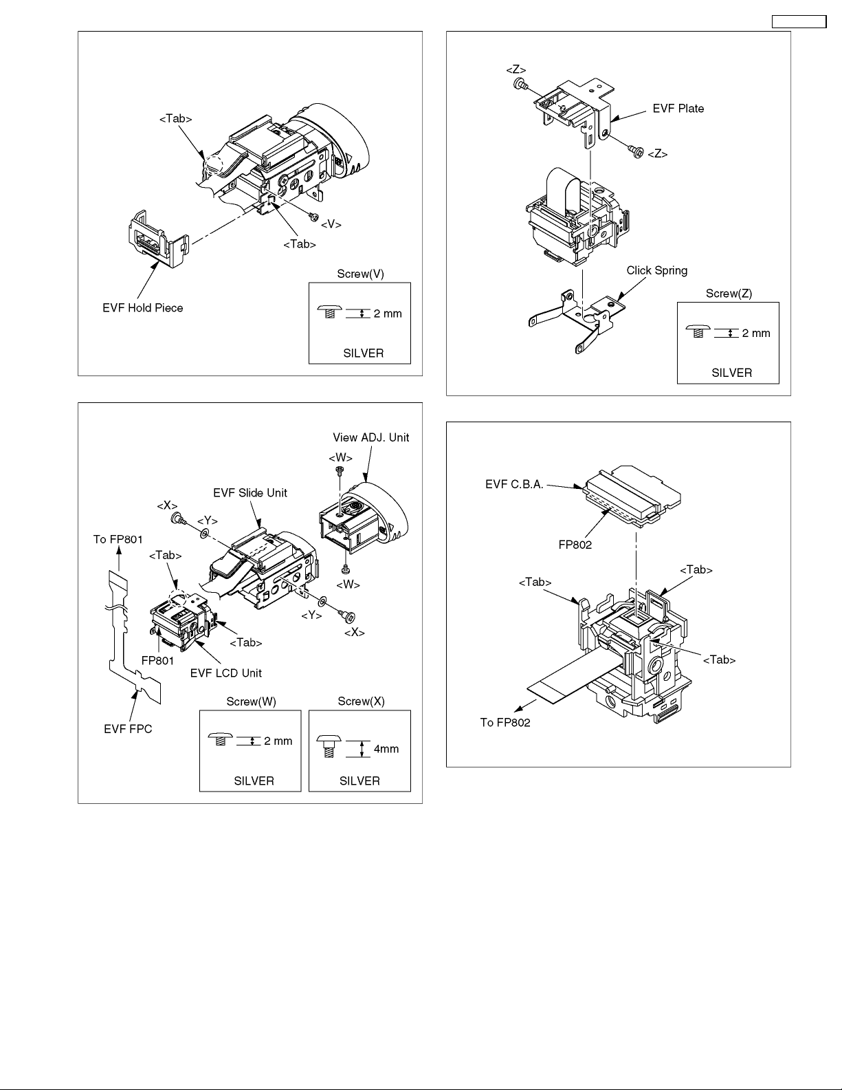
Fig. D21
PV-GS150PP
Fig. D23
Fig. D22
Fig. D24
19
Page 20
PV-GS150PP
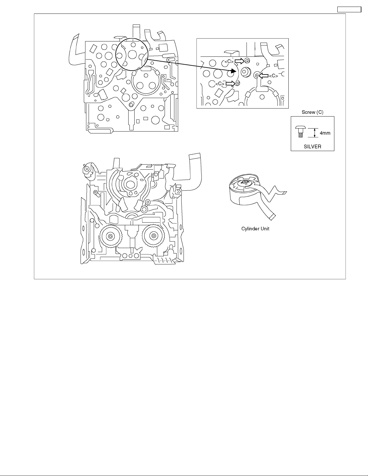
7.3. DISASSEMBLY PROCEDURES MECHA. UNIT
Flow-Chart for Disassmbly Procedures
No. Item / Part Fig. Removal (Screw, Connector, Flex. & Other)
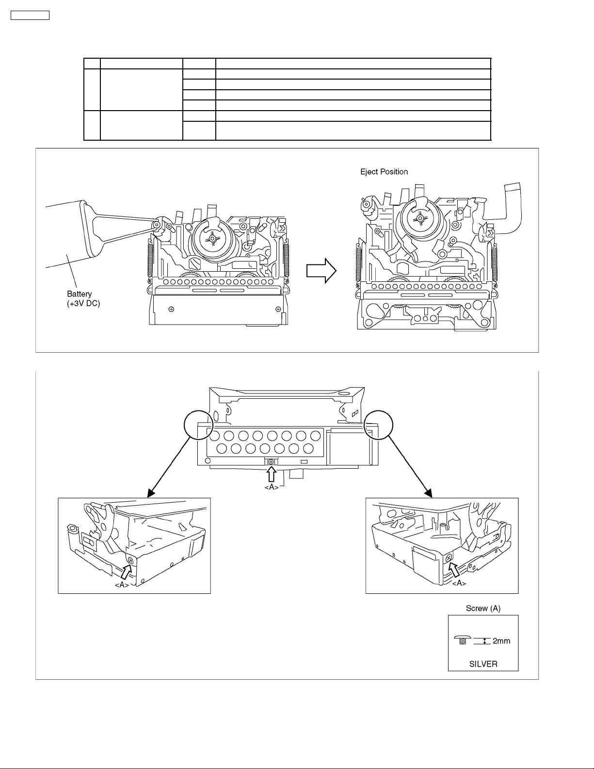
1 Cassette Up Unit Fig. M1 It makes the mechanism position in Eject condition (For Battery)
Fig. M2 3-Screws (A)
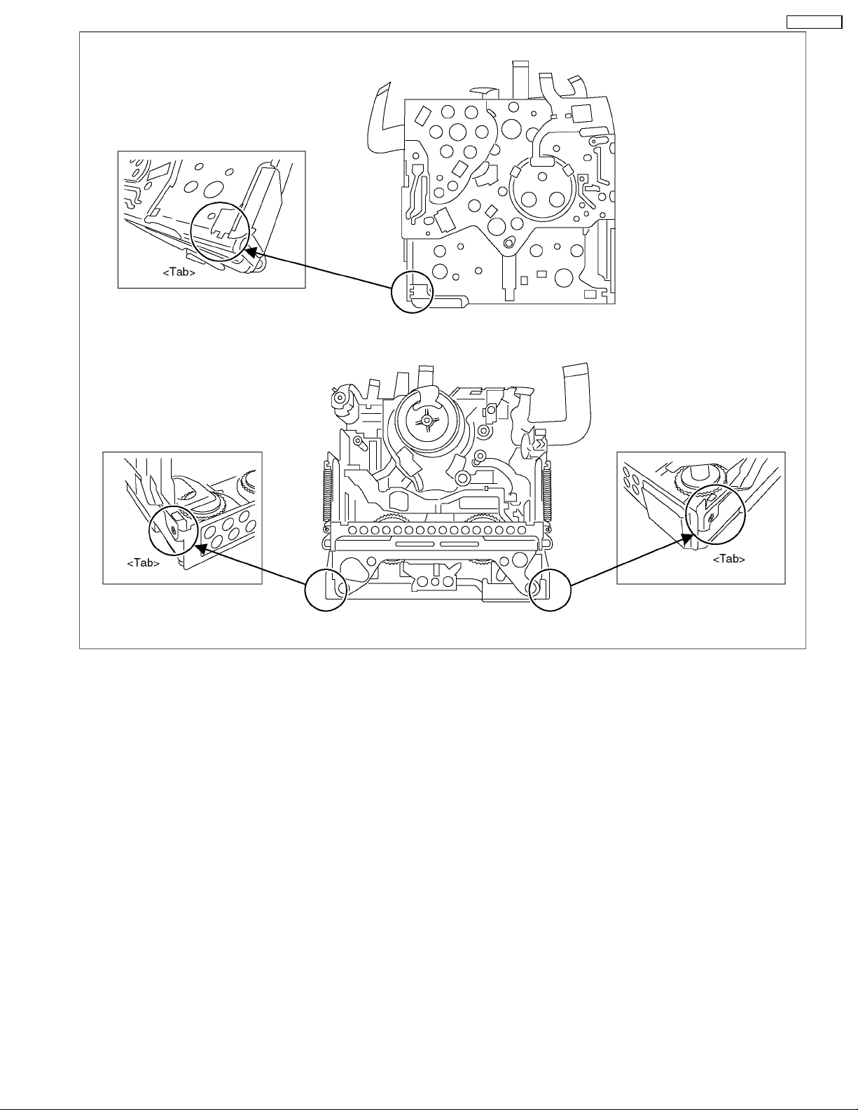
Fig. M3 3-Tabs
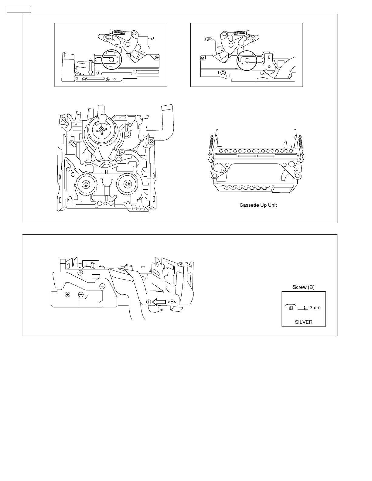
Fig. M4 It remove the piece arrangement unit from rail department
2 Cylinder Unit Fig. M5 1-Screw (B)
Fig. M6 3-Screw (C)
Cylinder Unit
Fig. M1
Fig. M2
20
Page 21
PV-GS150PP
Fig. M3
21
Page 22
PV-GS150PP
Fig. M4
Fig. M5
22
Page 23
PV-GS150PP
Fig. M6
23
Page 24
PV-GS150PP
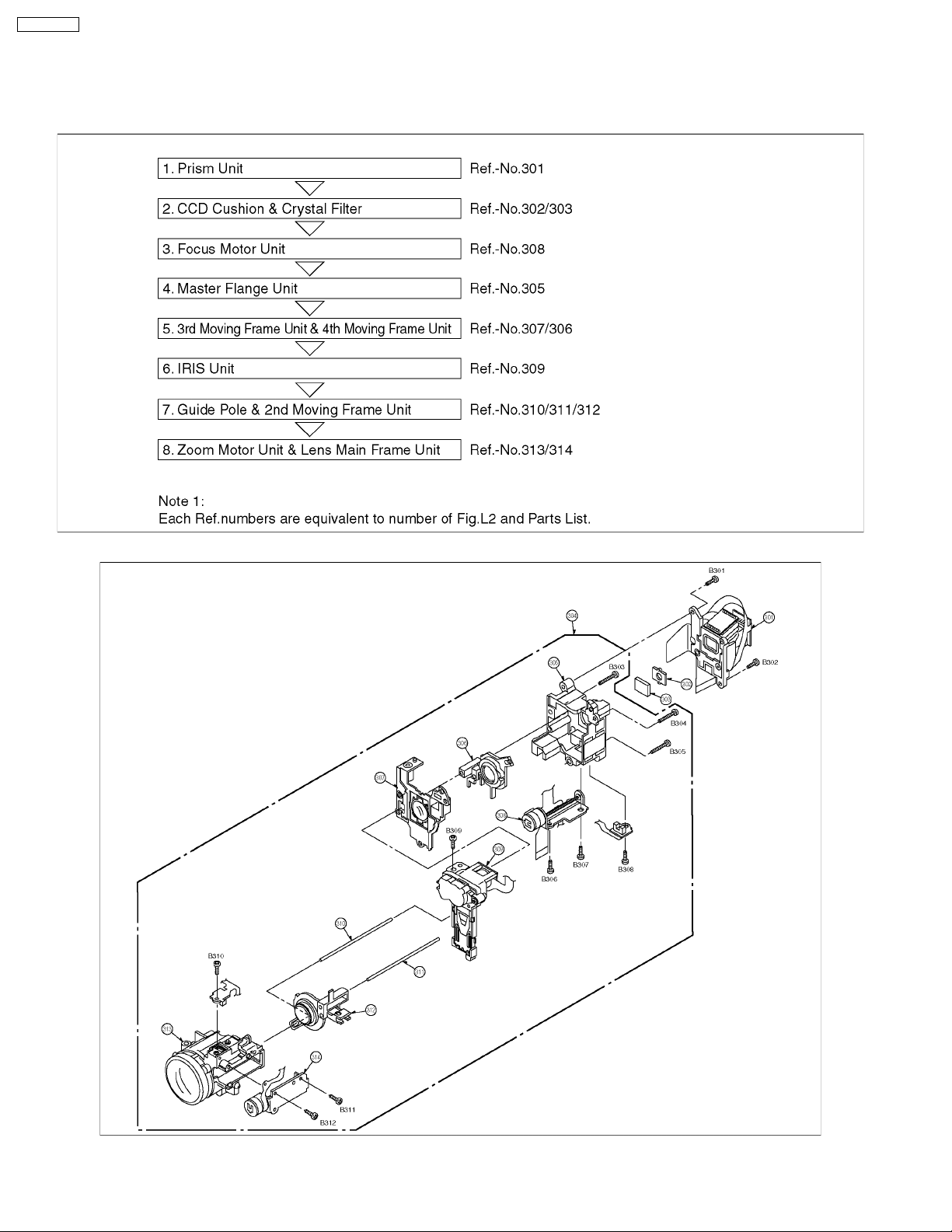
7.4. DISASSEMBLY PROCEDURES OF CAMERA LENS UNIT
The following flowchart describes order or steps for removing the Camera lens unit and certain printed circuit boards in order to
make access to the item needing service.
To reassemble the unit follow the steps in reverse order.
Fig. L1
Fig. L2
24
Page 25
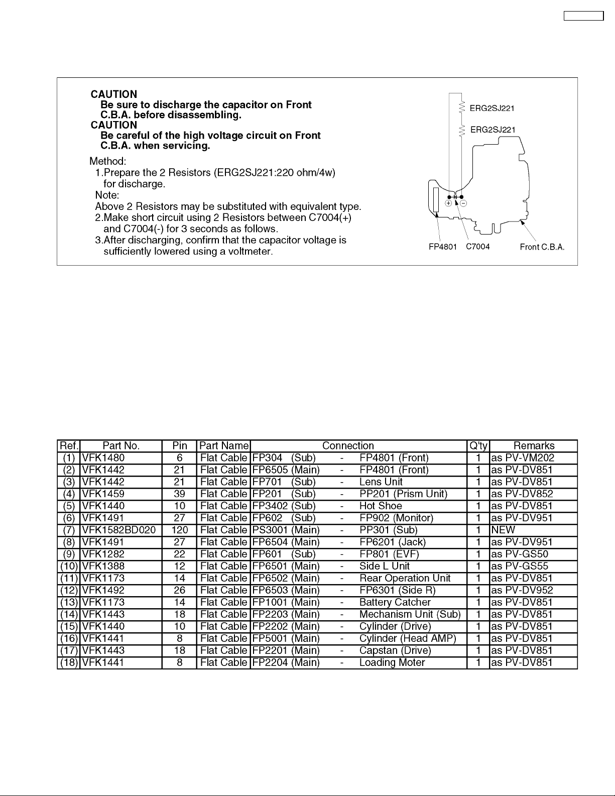
8 SERVICE CAUTION
8.1. HOW TO DISCHARGE THE CAPACITOR ON FRONT C.B.A.
8.2. EEPROM DATA FOR SPARE PARTS OF THE MAIN C.B.A.
PV-GS150PP
When the Main C.B.A. is replaced, the fixed and average data must be changed by Tatsujin kit according to the Movie Camera’s
suffix.
Then, confirm and/or adjust the VTR and Camera section one by one.
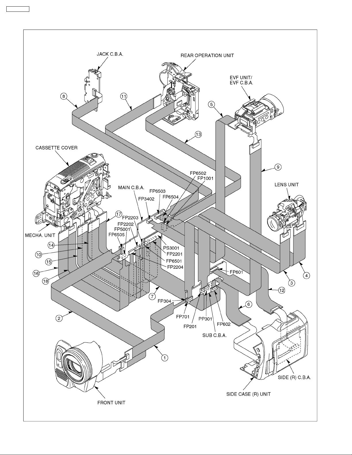
8.3. SERVICE EXTENSION CABLE FOR ALL C.B.A. INCLUDED IN MODULE
UNIT
This models is required the following extension cables for all connections.
Use the following extension cables when checking or adjusting individual circuit boards.
25
Page 26
PV-GS150PP
How to use extension cables.
Fig. T1
26
Page 27
8.4. LOCATION FOR CONNECTORS OF THE MAIN C.B.A. & SUB C.B.A.
8.4.1. MAIN C.B.A.
FP6503
K1MN26A00068
FP3402
K1MN10A00074
148
5
IC2006
(EEPROM)
FP6505
K1MN21BA0058
PS3001
K1KBC0A00037
PV-GS150PP
FP1001
K1MN14BA0062
FP5001
K1MN08BA0009
FP2204
K1MN08BA0010
FP2202
K1MN10BA0008
FP6501
K1MN12BA0059
FP2203
K1MN18BA0010
FP2201
K1MN18BA0008
PP3001
K1KA20B00154
(COMPONENT SIDE)
FP6502
K1MN14BA0061
27
FP6504
K1MN27BA0058
(FOIL SIDE)
Page 28
PV-GS150PP
8.4.2. SUB C.B.A.
FP701
K1MN21BA0058
FP201
K1MN39BA0058
FP601
K1MN22A00065
FP602
K1MN27BA0058
FP304
K1MN06BA0107
PP301
K1KAC0A00014
(COMPONENT SIDE)
28
(FOIL SIDE)
Page 29
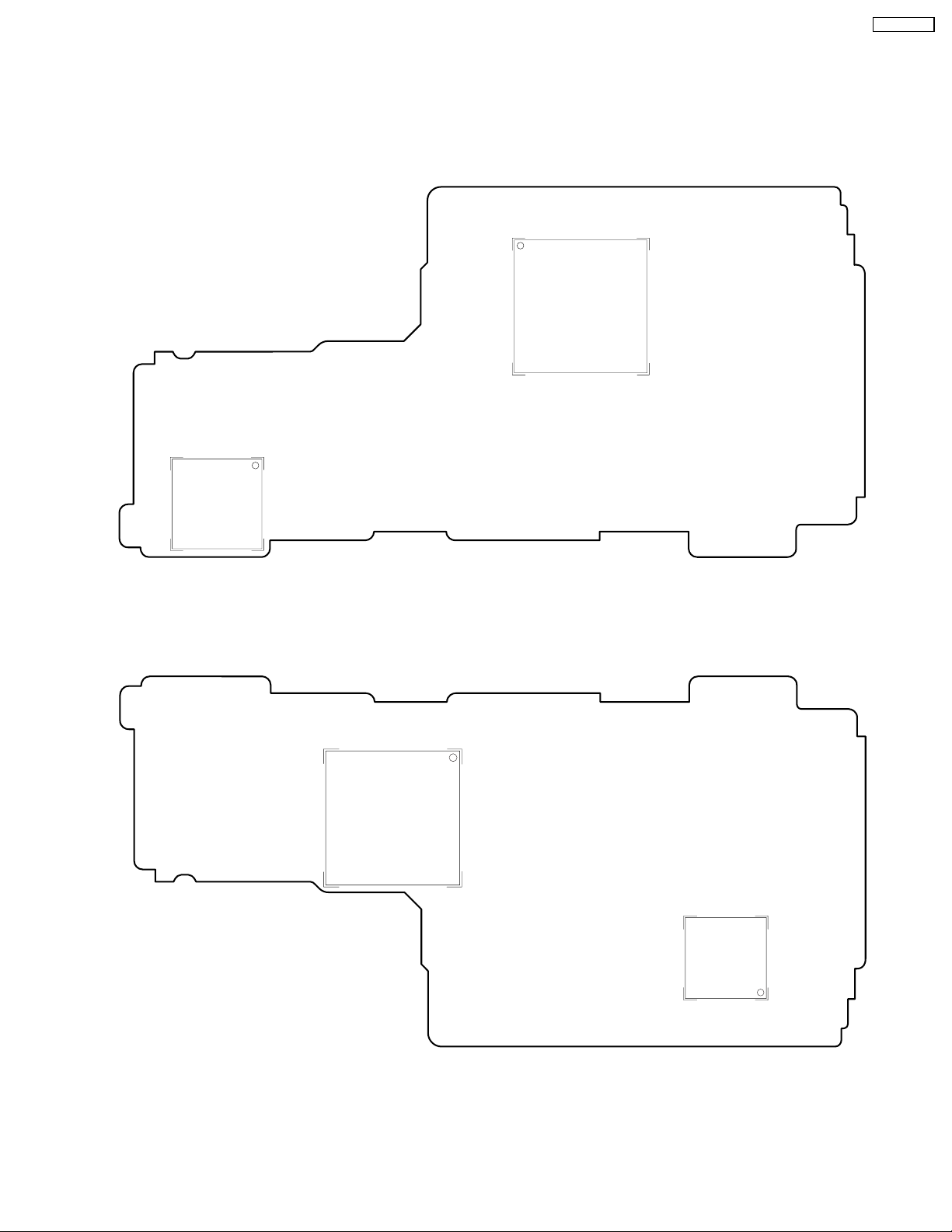
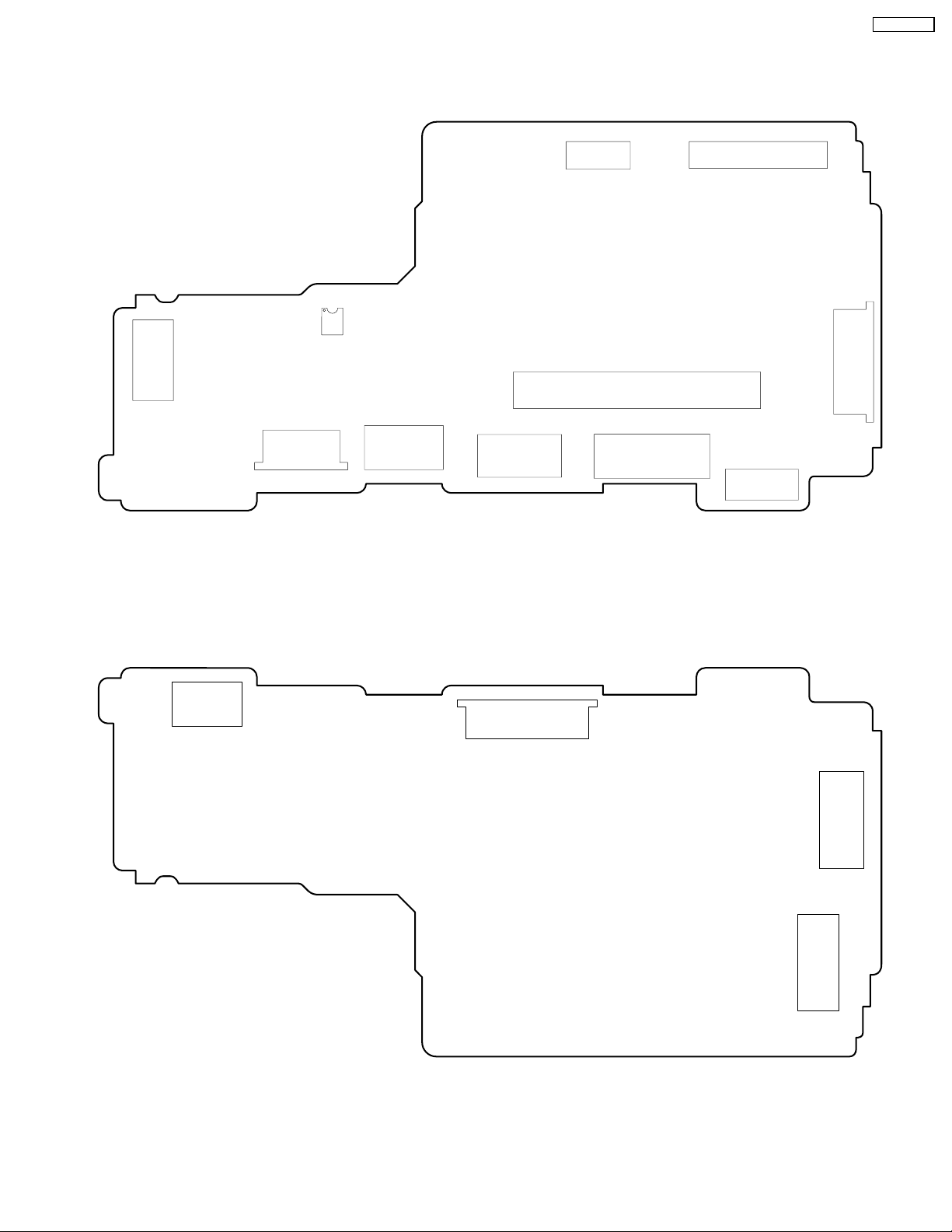
8.5. CSP IC LOCATION OF THE MAIN C.B.A. & SUB C.B.A.
Make sure to install CSP IC in the correct position of the Main C.B.A. & Sub C.B.A. as shown.
8.5.1. MAIN C.B.A.
IC3001
IC3201
PV-GS150PP
IC2001
(COMPONENT SIDE)
IC3801
29
(FOIL SIDE)
Page 30
PV-GS150PP
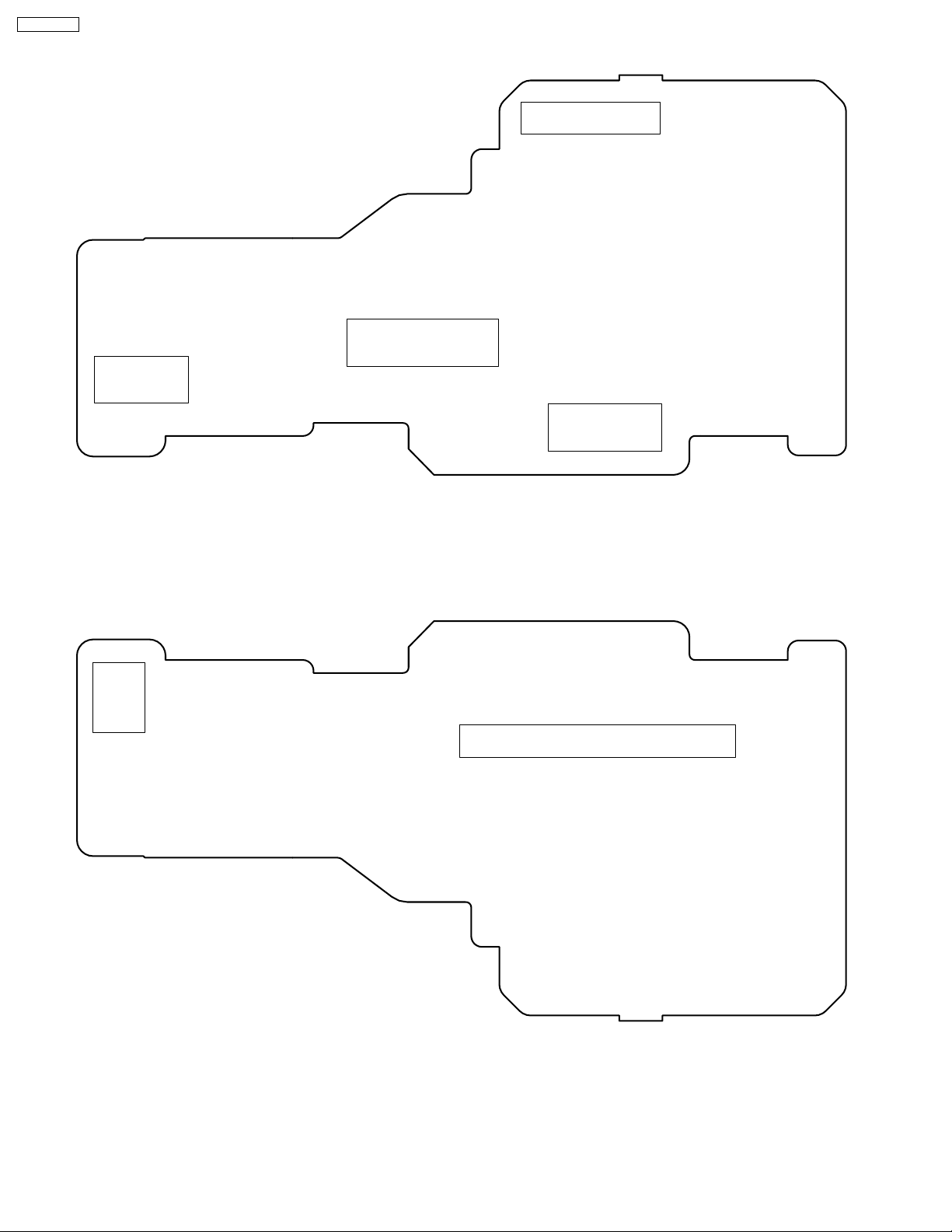
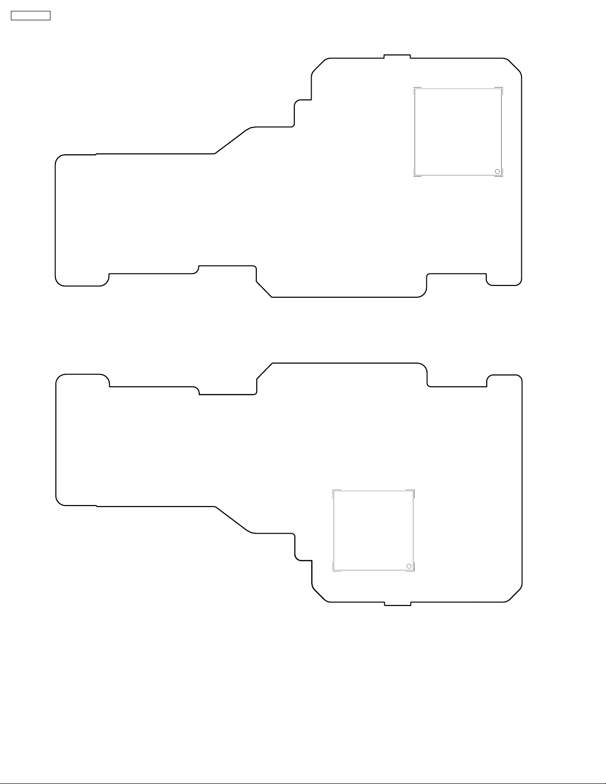
8.5.2. SUB C.B.A.
IC303
IC305
(COMPONENT SIDE)
30
(FOIL SIDE)
Page 31

8.6. TEMPERATURE PROFILE FOR HEAT RESISTANCE OF CSP IC
When using equipment other than the Pre-Heater, refer to the temperature profile.
CSP ICs for Model of PV-GS150 have the following temperature profile.
PV-GS150PP
8.6.1. IC TEMPERATURE PROFILE
(IC303)
8.6.2. IC TEMPERATURE PROFILE
(IC305)
8.6.4. IC TEMPERATURE PROFILE
(IC3001)
8.6.5. IC TEMPERATURE PROFILE
(IC3201)
8.6.3. IC TEMPERATURE PROFILE
(IC2001)
8.6.6. IC TEMPERATURE PROFILE
(IC3801)
31
Page 32

PV-GS150PP
9 ELECTRICAL ADJUSTMENT PROCEDURES
9.1. COMPUTER ASSISTED ADJUSTMENT SYSTEM <TATSUJIN>
ADJUSTMENT.
This unit employs the computer assisted system named; “TATSUJIN PC-Adjustment” for Electrical adjustment.
9.2. SET-UP MANUAL FOR DV-Camcorder.
1. SAVE THE SOFTWARE
Install the effective model’s TATSUJIN Software to PC: Personal Computer.
2. SET-UP (CONNECTION)
a. Remove the EVR cover of the DV Camcorder.
Unlock the locking tab and remove the EVR cover as shown in Fig. E1.
b. Make a connection.
Connect the PC, the PC/IF Unit and the DV Camcorder as shown in Fig.E2 and E3.
c. Check the SW position on Measuning Board.
The position of SW on Measuning Board checks as shown in Fig. E4.
Fig. E1
Fig. E2 Necessary Equipment & Tools for Connection.
32
Page 33

Fig. E3 Rough image of set-up connection
PV-GS150PP
33
Page 34

PV-GS150PP
Fig. E4
(Extension cables (VFK1317 × 2pcs) ----- Measuring Board (VFK1308E) ----- 232C I/F Cable (VFK1395))
34
Page 35

9.3. SET UP PC-EVR ADJUSTMENT PROGRAM
1. Turn on the PC and install the TATSUJIN Adjustment
Program into the PC.
2. Execute the “Gs150.exe“ file by double clicking to start up
the PC-EVR Adjustment Program.
The main menu will be displayed.
3. Select the desired model.
4. Turn on the camcorder. Then, click “Start.”
Note:
The adjustment data is stored to the EEPROM IC after
each adjustment.
7. After adjustment, to end the software, select “Exit” in File
Fig. E5-1
5. The communication is complete, and the dialog will appear.
Then, click “VCR (V) or Cam (C)” to save the EEPROM
data,
menu or close the window.
PV-GS150PP
Fig. E5-3
Fig. E5-2
6. Saving for EEPROM data is complete, menu will appear.
To perform each adjustment, display the adjustment menu
by selecting the desired menu from “Camera Adjust,”
“Video Adjust,” “LCD Adjust” or “EVF Adjust” and select
each adjustment item.
Fig. E5-4
35
Page 36

PV-GS150PP
9.4. INITIAL GUIDELINE
The table below shows which adjustments are necessary according to the unit parts and individual parts to be replaced. Make sure
to perform these adjustments shown below as necessary.
36
Page 37

10 MECHANICAL ADJUSTMENT PROCEDURES
10.1. ADJUSTMENT ITEM
Item Adjustment at the time of the part exchange
Half finished goods mechanism Clyinder Remarks
Linearlty adjustment& BER value
confirmation
10.2. ADJUSTMENT PROCEDURES
llllLinearlty adjustment & BER value confirmation
1. Remove the mechanism adjustment cover of tis machine as shown in Fig. D1.
2. The spcial tool at the time of electricity adjustment is connected.
Reference of the connection figure of electricity adjustment.
3. The enbelope detection spcial tool board (VFK1641) is connected to EVR adjustment board as shown in Fig. D2.
4. The enbelope detection spcial tool board is connected to oscilloscope as shown in Fig. D2.
5. The post is adjusted with the post driver(VFK1899) so that recycles the standard tape and the detection wave-link become
a flat as shown in Fig. D3.
*At the time of the clyinder unit exchange unnecessary.
6. The post is adjusted with the post driver so that recycles a alignment tape(VFM3010EDS) and the detection wave-link
become a flat once again.
7. Recycling the tape that video-taped it wirh this machine after adjustment, the BER value is confirmed withthe item of the
BER the item of the BER confirmation of expert soft inside.
PV-GS150PP
Fig. D1
37
Page 38

PV-GS150PP
Fig. D2
Fig. D3
38
Page 39

11 SERVICE MODE
11.1. ERROR DISPLAY
“PUSH THE RESET SWITCH” is displayed automatically on the EVF or the LCD Monitor when an undesirable condition has
occured.
PV-GS150PP
11.2. SERVICE MENU
When abnormal detection contents are confirmed a When I do the following operation automatic diagnosis cord is
displayed. (Service Menu)
To enter the Service Menu
Press the [QUICK START] button and [JOYSTICK LEFT
(with no SD card inserted).
NOTE:
In the case that a tape or SD card is included the above operation does not work.
This function displays the following items in the Service Menu.
· *1 ... Cylinder elapsed time reset
After replacint the Cylinder Unit, clear the Cylinder elapsed time to 0.
Set to Service Menu.
Item [8] is selected with the [JOYSTICK UP or DOWN
It modes to the [OFF / ON] screen with the [JOYSTICK RIGHT
[ON] is selected with the [JOYSTICK UP or DOWN
Press the [JOYSTICK CENTER] button.
· *2 ... Cylinder elapsed time
This item displays the Cylinder elapsed time (in Base 16).
Set to Service Menu.
Item [3] is selected with the [JOYSTICK UP or DOWN
It modes to the [OFF / ON] screen with the [JOYSTICK RIGHT
[ON] is selected with the [JOYSTICK UP or DOWN
Press the [JOYSTICK CENTER] button.
] button and [PHOTO SHOT] button simultaneously for 3 seconds
/ ] button.
] button.
/ ] button.
/ ] button.
] button.
/ ] button.
39
Page 40

PV-GS150PP
Calculation method of the Cylinder elapsed time:
· *3 ... Mechanism lock code record
The current lock code, the last lock code and the lock code before last are displayed in the item [3] screen.
· *4 ... Lens motor lock code record
The current lock code, the last lock code and the lock code before last are displayed in the item [3] screen.
Cylinder elapsed time and lock code (Item [3] screen)
DISPLAY CONDITION
Mechanism & Lens motor lock code
01 T-REEL LOCK
02 S-REEL LOCK
03 UNLOADING LOCK
04 LOADING LOCK
05 CYLINDER
51 ZOOM MOTOR LOCK
52 FOCUS MOTOR LOCK
To exit the Service Menu
Unplug the AC Cord.
Please do the error cord backup record the clear after repair completion.
CLEAR METHOD
If the Card and Tape inserted, take out it before Service Mode operation.
Making the mode dial of This Machine a PC connection mode, push [QUICK START] button and [JOYSTICK LEFT
button and [RECORDING START/STOP] button simultaneously for 3 seconds.
NOTE:
1. Do not operate items 1 ~ 7 (Except for 3) in the Service Menu.
]
40
Page 41

12 ABBREVIATIONS
PV-GS150PP
INITIAL/LOGO ABBREVIATIONS
A A GND Analogue GND
A HASW Audio Head Amp Switching Pulse
A HSW Audio Switching Pulse
A MUTE Audio Mute
A ORP Audio Overlap Pulse
A. TR Auto Tracking
A0-8, 0-17 Memory Address
A3V2 AD Converter Reference Voltage
AB0-4 Address Bus
AB0-4, AB12-15 Address Bus Line 0-4, 12-15
ABSF Focus Encoder Input
ACI Analogue Channel Cording IC
AD AD Converter
AD Auto Date, Analogue Digital Converter
AD CLK AD Clock
AD REC Audio Delayed REC
AD0-6 Address
AD0-6, ADR0-6 Address Data Line
ADCLK Analogue Digital Converter Clock
ADCNT Analogue Digital Control
ADCS Analogue Digital Chip Select
A-DET Audio Detect
ADREC Audio Delaied Rec
ADUB Audio Dubbing
AE Auto Expose
AECNT Auto Expose Control
AEE(H) Audio E-E (H)
AEH Audio Erase Head
AEIRQ Auto Expose Interrupt Request
AF/MF Auto Focus/Manual Focus
AF DIS CS AF DIS Chip Select
A-FADE(L) Audio Fade (L)
AF-AMP AF HALL Bias
AFCS Auto Focus Chip Select
AFRP Audio PLL Voltage Control
AF-VN Zoom Encoder V-Ref (–)
AF-VP Zoom Encoder VREF (+)
AGC Automatic Gain Control
AGCCNT Automatic Gain Control Control
AGND Analogue Ground/Audio Ground
AGS Anti Ground Shooting
AH(P) / (R) Audio Head (Play) / (Record)
AHASW Audio Head Amp Switch Pulse
AHSW Audio Head Switch Pulse
AI, AO Buffer Input, Output
AIBCK Bit Clock (to A/D Converter)
AIDAT Serial Data (to A/D Converter)
AILRCK L/R Clock (to A/D Converter)
AIMCK Master Clock (to A/D Converter)
ALC CNT Auto Level Control Control
INITIAL/LOGO ABBREVIATIONS
ALC MAIN Auto Level Control Drive
ALE Address Latch Enable
A-LOCK Full Auto Switch
A-MUT(H) Audio Mute (H)
ANLPTH Analogue Loop Through High
AORP Audio Overlap Pulse
APCNT Aperture Control
APS Auto Power Save
ART VH Artifical Vertical Sync
AT CNT Automatic Tracking Gain Adjust
ATF Automatic Track Finding
ATFCLK 41.85MHz Clock
ATFG Auto Track Gain
ATL Auto Lock Select
ATN Absolute Track Number
ATR OFF(H) Auto Tracking Off (H)
ATV Advanced TV
AUDIO(N) Audio (Normal)
AUX Auxiliary
AVDD Analogue VDD
AVSS Analogue Ground
AWTB Auto White Balance B-Y
AWTR Auto White Balance R-Y
B BACK Back-up
BACK UP Microcomputer Back-up
BACK VDD Back-up Power
BATT Battery
BATT ALARM Battery Alarm
BATT REF Reference Voltage for Battery
BCB B Carrier Balance
BCBM(B-Y) B-Y Carrier Balance
BCBM(R-Y) R-Y Carrier Balance
BD0-7 REC/Play In/Out Buss
BDCK Standard Bus Data Clock (9MHz)
BDEN Standard Bus Data Enable
BEND Data Block End Request
BF Burst Flag Pulse
BFA Burst Flag Pulse for Encorder
BFO/BFI Burst Flug Input/Output
BI, BO Buffer Input, Output
BL Back Light
BL ON Back Light ON (L)
BL4V Back Light 4V
BLC 0, 1 Back Light Y Control Out, In
BLDI/O Back Light Drive Input/Output
BLK Blanking Pulse
BLKA Blanking for Encorder
BLKA Blanking Pulse for Encorder
BLKI/O Blanking Pulse In/Out
41
Page 42

PV-GS150PP
BLKZ Blanking Pulse for Zoom Encorder
BM Balance Modulator
BQUIET Bus Out Control Signal
BUF IN/OUT Buffer In/Out
B-Y KB B-Y Carrier Balance
B-YO B-Y Signal Out
C C A In/Out Pre-Aperture In/Out
CAPSTP Capstan Stop Flag
C CNT Colour Control
C SYNC Composite Sync Signal
C/N Carrier/Noise
C0-7, C00-07 Chrominance Signal 0-7
CAGAIN Aperture Gain Control
CAM Camera
CAM CLK Camera Clock
CAM RST Camera Reset
CAM SIOC Camera Serial In/Out Contol
CAM T Camera Test
CAM TL Capstan Trque Limit
CAP EC Capstan Trque Control
CAP P(H) Capstan Power On (H)
CAP R/F/S Capstan Reverse (H)/Stop (M)/Forward (L)
CAP SW Capstan Power Control Switch
CAPSTP H Capstan Stop Flag (Stop High)
CAPVM Capstan Motor Current
CAPVS Capstan Motor Power Control Switch
CAS
Compresion, Audio Process, Shuffling/Deshuffling
CAS Memory Address Strobe (Active Low)
CASDOWN, DWN Cassette Down (L)
CB, CR Chroma B, Chroma R
CBLK Composite Blanking Pulse
CC Channel Cording
CCA Curent Drive Control
CCA Current Control Amp
CCD Charge Coupled Devise
CCW Counterclockwise
CD SP0-7 Digital Chroma
CDS Correlate Double Sampling Signal
CDS1, 2 Sampling Pulse for CCD Output Signal
CE Chip Enable
CE Control Pulse Erase
CEC Capstan Error Code
C-ERA(H) Control Erase (H)
CFEM Chrominance Memory Signal
CFM Chrominance Field Memory
CFM1-4 Chroma Field Memory Signal
CG CLK Character Generator Clock
CG CLK DATA Clock Generator Data
CG DATA Character Generator Data
CGC Chrominance Gain Control
CGCS Character Generator Chip Select
CGO Character Generator Serial Data
CH Charge
INITIAL/LOGOINITIAL/LOGO ABBREVIATIONS
ABBREVIATIONS
CH1 Channel 1 (Odd Field)
CHR Character
CHR BACK Character Back-up
CHR MIX Character Mix
CI, CO Buffer In/Out
CI,CO Buffer Input & Output
CIF Control Signal Forward Input
CIF, CIR
Positive Control Pulse, Negative Control Pulse
CIR Control Signal Reverse Input
CK Clock
CL/CLK Clock
CLASS
Classeffication Signal for Compress (DCT/VLC)
CLASS 0.1 Class Control Signal Durring DCT/VLC
CLK135 13.5MHz System Clock
CLK18 18MHz System Clock
CLK2 Clock 2 (824XFH: 12.875MHz)
CLK246 24.576MHz Clock
CLK27 27MHz System Clock
CLK450 450KHz Clock
CLKDCLK Digital Clock
CLK-PH Clock Phase Control
CLK-REF Reference Clock
CLP-RST-H Clamp Reset High Signal
CLX TFT X-axis Transmission Clock
CLX, CLX1-4 Shift Clock for X Direction (LCD Panel)
CLY Shift Clock for Y Direction (LCD Panel)
CLY TFT Y-axis Transmission Clock
CLY FG Cylinder FG Signal
CMEMO0-3 Chroma Memory Output Signal 0-3
CMIX Character Mix
CMO Chrominance Memory Output
COMPC Position Detection Pulse
COM RDY Serial Enable Signal
CMODE Camera Mode
CNCLK Clock
CNR Chrominance Noise Reduction
CNT, CONT Control
CO Control Out
CO0-7 Chrominance Output 0 to 7 (Digital)
COM Common
COM RDY Serial Transmission Enable
COMB Comb Filter
COS EQ Cosin Equalizer
CP Clamp Pulse
CP ON(H) Camera Power On(H)
CP2, 20 Clamp Pulse
CP2A, CP2O Encoder Clamp Pulse
CPN Component Signal
CPOB Clamp Pulse for Optical Blanking
CPS Composite Signal
CPV Gate Scan Clock
CR OUT Pre Apature Out
CR POW SW Camera Remote Power On Switch
CRA Aperture Gain Control
42
Page 43

CRA Pre Apature Gain Control
CRST Camera Reset
CS Chip Select
CS 0-7 Chrominance Signal Out 0-7
CSEL Clock Phase Select
CSI 0-7 Chrominance Signal In 0-7
CTSW Crosstalk Switch
CURR Current
CW Clockwise
CYL EC Cylinder Motor Trque Control
CYL PG Cylinder Motor PG
CYL VM Cylinder Motor Current or Power
D D CLK Digital Clock
D MODE Digital Mode Switch Signal
D01-03 Zoom 01-03
DA UV SEL D/A Convertor U/V Select
DAC Digital Analogue Converter
DAG Digital Analogue Ground
DB0-7 Data 0-7
DB0-7 Microprocessor Data
DCC DC Clamp Control
DCCNT DC Control
DCI Digital Channel Cording IC
DCLR Digital Clear
DCP Digital Clamp Pulse
DCS-CLK, DA CAS & DV I/F Serial Clock
DC-STP1 DCS Serial Start
DC-STP2 DCS Serial Stop
DCT Discrete Cosine Transform (Compression)
DCX7 Serial Data
DEDP 0-3 Playback Data
DEDR 0-3 Rec Data
DEMO Demodulation
DEMP A/D Convertor Empahsis Control
DEMP De-Emphasis
DFD 0-7
DFD0-7
Encode Data In/Out Between Shaffling Memory
Encode Input/Output Signal for Shuffling Memory
DIBDCK Bit Clock
DICLK Digital Clock
DIDAT Serial Data
DIDAT Serial Data Durring Digital Audio In
DIF Digital Interface
DILRCK L/R Clock
DILRCK Serial Clock Durring Digital Audio In
DIMCK Master Clock
DIMCK Mater Clock Durring Digital Audio In
DIO 1-8 Data In/Out
DIOS Data In/Out Select Control Signal
DIOS Select Signal for Digital In/Out
DIS Digital Image Stabilizer
DIS R/B Digital Image Stabilizer Read (H)/Busy (L)
DIS R/B DIS IC Rady/Busy
DIS/KAND Digital Image Stabilizer/Sensitivity
INITIAL/LOGOINITIAL/LOGO
ABBREVIATIONSABBREVIATIONS
DISCS Dis Chip Select
DISP Display
DL Delay Line
DOBCK Audio A/D Convertor Bit Clock
DOCTL Data Output Control Signal
DODAT Serial Data (to D/A Converter)
DOLRCK Audio A/D Converter LR Clock
DOLRCK L/R Clock (to D/A Converter)
DOMCK Audio A/D Converter Master Clock
DOMCK Master Clock (to D/A Converter)
DQ 1-16 Memory Data
DRAM CAS D-RAM Colum Address Strobe
DRAM OE D-RAM Out Enable
DRAM RAS D-RAM Read Address Strobe
DREC AV Delayed REC Start Pulse
DRK Dark (LPF Switch for Auto Focus)
DS1, 2 Double Sampling Pulse
DSF 0-7 Data In/Out for Shaffling Memory
DSF 0-7
Input/Output Data to Shuffling Memory (18MHz)
DSP Digital Signal Processor
DSP R/B DSP IC Rady/Busy
DSP-48K-H DSP IC Clock Select
DSTB Data Stobe Signal
DSV Digital Sum Variation
DV Digital Video
DVB Digital Video Broadcast
DVC Digital Video Cassette
DVDD Digital VDD
DVIO Digital Video Input Output
DVSS Digital Ground
DX Shift Data for X Direction (for LCD)
DY Shift Data for Y Direction (for LCD)
DY TFT Y-axis Shift Data
DZ Digital Zoom
E E Snap Electric Snap Shot
E ZM Electric Zoom
E2 CS or E2P CS EEPROM Chip Select
E2 R/B EEPROM Rady/Busy
E2P EEPROM
EARP Earphone
EC Torque Control
ECC Error Correction Cording
ECM Electric Condencer Mic
ECR Reference Voltage for Capstan Torque
EDA Error Correction, DCI, ATF Servo
EE CS EEPROM Chip Select
EE R/B EEPROM Read (H)/Busy (L)
EEPROM
Electric Erasable Programable Read Only Memory
EIS Electric Image Stabilizer (DIS)
EMP A/D Convertor Emphasis Control
ENAB Enable
ENV Enverope
EOB End of Block
PV-GS150PP
43
Page 44

PV-GS150PP
EQ Equalizer
EVF Electric View Finder
EXT DC External DC (AC Adaptor)
EXT DC(H) AC Adaptor DC (H)
EXT NOREG AC Adaptor 6V
EXT S DATA Serial Data for Edit
EXT SCK Serial Clock for Edit
EZOOM Electric Zoom
F
F ENC Lens F-Value
FACT MODE Factry Mode (not used in the service)
FB Feed Back
FC Saw Tooth Signal In
FCK Clock
FCO Saw Tooth Signal Generator
FENC Focus Encoder
FEND Frame End Pulse
FH2B FH/2 (15.625KHz / 2=7.8125KHz)
FIX OSD Auto Tracking Off (H)
FLICK Flicker Output
FM Field Memory
FM0-7 Field Memory 0-7
FMCO0-3 Field Memory Chrominance Out 0-4
FMDIR Focus Motor Direction
FMOEM Field Memory Enable
FMOEO Field Memory Enable
FMT1-4 Focus Motor Terminal 1-4
FMY00-07 Field Memory Luminance Out 0-7
FMYI0-07 Field Memory Luminance In 0-7
FNO F Value
FPS Frame Refference Signal
FR Capstan Reverse High
FRP Frame Refference Pulse
FRPSO Frame Start Pulse
G G1, G2, G3 Gap 1, 2 and 3
GCA Gain Control AMP
GCNT Gain Control
G-CNT AGC Adjustment
GCTRL Gain Control
GENE Generator
GF FG AMP Terminal
GSW Ground for Switching Power
H H/M/N Hi-Fi / Mix / Normal
H/N Hi-Fi / Normal
H1, 2 H. CCD Drive Pulse
HAP Horizontal Aperture
HASW Head AMP Switching Pulse
HB Hall Bias
HBR SET High Brightness Set
HBRST High Brightness Set
HCLR High Clear
HCP Shift Clock for Horizontal Drive
INITIAL/LOGOINITIAL/LOGO ABBREVIATIONS
ABBREVIATIONS
HD Horizontal Drive Pulse
HDTV High Definition TV
HEX Hexadecimal
HG Hall Gain
HID Head Switching Pulse
HLT High Bright Signal
HALL IN(+), (–) Input Signal from Hall IC
HP Headphone
HPF High Pass Filter
HSE Modulated Data Output
HSP Timing Pulse for Shaffling Memory
HSS Horizontal Sync Signal
HSW Head Switching Pulse
HS-WT High Speed Zoom
HSZ High Speed Zoom
I I/F Interface
I-2 C Inter Integrated Circuit
ID(H) Wide Television (H)
IMP Inter Microprocessor Protocol
INF CCD Input Signal 1
INF Input Frame Signal
INS CCD Input SIgnal 2
INTER Interval Recording
INV Inverter
IOU R-Y Analogue Signal Output
IOV B-Y Analogue Signal Output
IOY Y Analogue Signal Output
IR Infrared Rays
IRDET Imfrared Ray Detection
IREF Current Adjustment Terminal
IRIS/SH Iris / Shutter Control
IRQ Interrupt Request
ITI Insert & Track Information
J JPEG
Joint Photographic Image Cording Experts Group
K KANDO Digital Gain Up
KB Carrier Balance
KEY IN Key Scan
KND Digital Gain Up
KNEE Luminance Compensate
L LCD Liquid Crystal Display
LCD P(L) LCD Power On (L)
LD Load Pulse
LDD Liquid Direct Drive
LEDCNT LED Control
LI-BATT Lithium Battery
LOAD Loading
LOAD F, R Loading Direction (F: Forward / R: Reverse)
LPF Low Pass Filter
LRMONO Monoral Audio (L + R)
LSB Least Significant Bit
44
Page 45

LVL LPF Switch for Auto Focus
M M1-3 Motor Coil Terminal 1 to 3
MA0-5 Microprocessor Address Data 0-5
Mbps Megahertz Bit Per Second
MD Modulation
MD0-7 Microprocessor Data 0-7
MDT0-7 Microprocessor Data 0-7
ME (TAPE) Metal Evaporated (Tape)
MENB Focus Motor Enable
MFF Manual Focus Far
MFN Manual Focus Near
MHSYNC Monitor Horizontal Sync Signal
MIC Memory In Cassette
MIG Meta In Gap
MIX N.R.D. Non Rec Data Mix
MOD Modulation
MOUT Mic Out
MP (TAPE) Metal Particle (Tape)
MPEG Moving Picture Image Cording Experts Group
MPEG2
Moving Picture Image Cording Experts Group Phase 2
MRST Focus Motor Reset
MSB Most Signal Bit
MVSYNC Monitor Vertical Sync Signal
N N/F Near/Far Focus
N/P NTSC/PAL
NB1-3 Base for NPN Transistor
NC No Connection
NC1-3 Corrector of NPN Transistor
NCLR Power On Reset
NCP1 Clamp Pulse
NCP2+VDH Clamp Pulse + Horizontal Drive Pulse
NCP2+VDM Clamp Pulse + Gate Pulse
NDE Non Liner De-Emphasis
NE Emitor of NPN Transistor
NLE Non Liner Emphasis
NR Noise Reduction
NRD Non Rec Data
NRD BLK Non Rec Data Blanking
NRD CLK No Rec Data Clock
NRE Read Enable Input (Low Active)
NWE Write Enable (Low Active)
O OB Optical Black
OBCNT Optical Black Control
OBREF Reference Voltage for Optical Black Control
OE Output Enable
OFH
Horizontal Counted Down Clock Signal (Reference)
OFS Offset
OP Operation AMP Output
OSD ON Screen Display
OVL Overlap Pulse
OZ Optical Zoom
INITIAL/LOGOINITIAL/LOGO ABBREVIATIONS
ABBREVIATIONS
P P SW Power Switch
PB1-3 PNP Base 1-3
PBCTL Play Back Control
PBCTL Pre-Branking Control
PBH Head Amp Switch
PBLK Pre-Blanking (Pulse)
PC1-3 Corrector of PNP Transistor
PCBM Carrier Balance
PCH Phase Compensator (Hall AMP)
PCI Phase Compensator (Current)
PCO Phase Compensator Out
PCS Switching Power Control
PCV Phase Compensator (Voltage)
PE Emitter of PNP Transistor
PED Pedestal
PEDECNT Pedestal Control
PENO Alarm (L)
PFP Pilot Frame Position
PGA, B Power Ground A, B
PGC Pulse Generator Comparator
PGI Pulse Generator Input
PGMM Pulse Generator Monostable Multivibrator
PGO Output of Pulse Generator AMP
PMODE Select Signal for Normal / Wide Screen
PON Power On
POR Power On Reset
POSCOM Common Position
PREAMP Pre-AMP
PREBLK Pre-Blanking
PT Protect for V Voltage
PWM Pulse Width Modulation
PWMB Pulse Width Modulation Pulse
Q Q2H Source Output Select
R R CTL P Recorded Control Pulse (+)
R CTL R Recorded Control Pulse (–)
R/B Read/Busy
R/L Direction Control for Data Transmition
RA Recording AMP
RA1 Rec AMP 1
RAC AC Rec Audio Current
RAD Read Address Data
RAE Read Address Enable
RB Read Busy
R-B R Bias
RCB R Carrier Balance
RE Read Enable
RE(F), (S) Rotary Erase Head Transformer
REB R Bias
REC CC Rec Current Control
REC CCNT Rec Current Control
RECCTRL Recording Control Pulse
RECI Rec Amp Switch
PV-GS150PP
45
Page 46

PV-GS150PP
RENCF Lens Control (Forward)
RENCR Lens Control (Reverse)
RERASE Rotary Erase Head
RGBIV1-2 1V Inverted Signal 1-2
RGO R/G OFF Offset Voltage for AWT R
RSF Capstan Direction (Reverse / Stop / Forward)
RST Reset
RSTB R Strobe
RSTPWD Reset Power Down Input
RSTR Reset Read
RSTW Reset Write
RT Saw Tooth Terminal
RVCO Resister for Oscillation
RW Read Write
RWAE Read Write Enable
S S PHOT Supply Photo Transistor
S/H Sampling Hold
S/S Start/Stop
SBD Serial Data
SBI Serial Data Input
SBO Serial Data Output
SBT Serial Clock
SCAN0-5 Key Scan 0-5
SCK Serial Clock
SCR Search
SCR, S.C.R. Still Cue Review
SEG. Segment
SET White Balance Set
SH/IRIS Shutter/Iris Control
SHIFT Capasitor for Phase Shift
SI Serial Data Input
SIC Shift In Clock Input
SIOC Serial In/Out Control
SMCE Shaffling Memory Chip Enable
SMRS Shaffling Memory Read Strobe
SMWE Shaffling Memory Write Enable
SMWS Shaffling Memory Read Strobe
SNAP Snap Shot
SNS LED Sensor LED
SO Serial Data Output
SPA ATF Smapling Pulse
SPEN 8 Bit Shift Register Enable
SPK Speaker
SPO Reset for Switcing Power
SPST 8 Bit Shift Register Strobe
SREELP Supply Reel Pulse
SRT Start
SSA Start Sync block Area
SSW Select Signal for Low Pass Filter
ST5V Safety Tab 5V
STAB Safety Tab Switch
STB Stand by Signal
STB Strobe
INITIAL/LOGOINITIAL/LOGO ABBREVIATIONS
ABBREVIATIONS
SWB Switching Pre-Drive Pulse
SYL EC Cylinder Torque Control
SYL FG Cylinder FG
T T PHOT Take-up Photo Transistor
TBC Time Base Conntrol
TFT Thim Film Transistor
TH Thermostat for Battery
TI Test Mode Select
TL Torque Limit
TM Sub Code
TMD Sub Code Data
TRE Tracking Error Signal
TREEL(P) Take-up Reel (Pulse)
TRFIX Tracking Fix
TRIWAVE Tracking Wave
TRP Tracking Position
TRP Trap
TSR Head Switching Refference
TST Time Scale Transfer
U U/V SEL R-Y/B-Y Select Signal
UNLOAD Un-Loading
UNRE Microprocessor Read Enable
UNWE Microprocessor Write Enable
UV R-Y/B-Y
UV SEL R-Y/B-Y Select Signal
V V1-V4 V. CCD Drive Pulse
VB VH Filter Switching
VCE Power Terminal
VCNTL Video Control
VCO Voltage Control Oscillator
VCP Shift Clock Output for Vertical Drive
VCTLD Video Control
VCTRL Voltage Charge Control
VD Vertical Drive Pulse
VDDX X Drive Power for Colour LCD
VDDXY XY Drive Power for Colour LCD
VDDY Y Drive Power for Colour LCD
VDREC Video Delayed Rec
Vgg Voltage for Gate IC
Vgl Gate off Voltage
VID Video Signal Out
VIN Video In
VITC Vertical Interval Time Code
VITERBI One of Signal Detection Method
VL Low Voltage
VLC Variable Length Cording
VLOCKP Artificial Sync Pulse
VLP Artificial Sync Pulse
VM Motor Voltage
VMD Velocity Mode Data
VMD1-3 Electric Shutter Mode
46
Page 47

INITIAL/LOGO ABBREVIATIONS
VMODE NTSC/PAL Select Switch
VMVH VH Filter Switching
VORP Video Overlap
VRB Voltage Refference Bottom
VRBS Voltage Refference Bottom Output
VREF1R3V Refference Voltage 1.3V
VREF3R3V Refference Voltage 3.3V
VREFH Refference Voltage High Side
VREFL Refference Voltage Low Side
VRI Refference Voltage Input
VRO Refference Voltage Output
VRT Voltage Refference Top
VRTS Voltage Refference Top Output
VS Switching Comparator
VSS Vertical Sync Signal
VSSX X Driver Power for Colour LCD
VSSXY X-Y Driver Power for Colour LCD
W W/N Mode Select for Window Mode
W/N Wide / Normal
WAD Write Address Enable
WAE Write Address Enable
WAERAE Write Address Enable
WARI Interrupt
WB White Balance
WE Write Enable
WEM Memory Write Enable
WHD Wide Horizontal Drive Pulse
WIDE A Wide Zoom
WSB B AGC Control
WSR R AGC Control
WTV Wide TV
PV-GS150PP
X XP FG Logic Reset
Y Y FM0-7 Y Field Memory 0-7
YCE Cylinder Error Code
YGC Y Gain Control
YMO 0-7 Y Field Memory 0-7
YNCST Noize Canceller
YNR Luminance Noise Reduction
YSDP 0-7 Digital Y Out 0-7
Z Z.ENC Zoom Encoder
Z.MIC Zoom Mic
ZENC Zoom Encoder Output
ZMDIR Zoom Drive
ZMEN Zoom Enable
ZMT Zoom Motor Tele Side
ZMT (+)/(–) Zoom Motor (+)/(–)
ZMTER Zoom Motor Tele Side
ZMW Zoom Motor Wide Side
ZSW Zoom Switch
47
Page 48

PV-GS150PP
48
Page 49

13 BLOCK DIAGRAM
13.1. OVERALL BLOCK DIAGRAM
LENS
PV-GS150PP
ZOOM
SUB C.B.A.
CAMERA
IC101
(CG/SSG)
2FCK
X101
IC307
(EEPROM)
IRIS
IC107,110
(INVERTER)
IC102
REG
IC305
(CAMERA
MICROCOMPUTER)
IC103
REG
FOCUS CCD
IC108
(V DRIVER)
IC104,105,106
(CDS,AGC,AD)
IC303
(DIGTAL
SIGNAL
PROCESSOR)
MMC/SD
S VIDEO
OUTPUT
VIDEO/AUDIO
OUTPUT
SPEAKER
IC3301 AVIO
(D/A,A/D,AV OUT AMP)
IC3001 DUO
(VIDEO I/O,VCO,COMPRESOR,
SHUFFLE,SHUFFLE MEMORY,
AUDIO PROCESSOR,ECC,
ECC MEMORY,1394 I/F,JPEG
COMPRESSION/EXPANSION,
CARD I/F,DAC)
FRONT(1/2) C.B.A.
IC4801
(MIC AMP)
AVIO
IC3201
RIP
(MODULATION,
VITERBI,EQ,
MOTOR DRIVE
CONTROL)
MIC
IC5001
(HEAD AMP)
EXT MIC/
FREE STYLE
REMOTE
CONTROL
DV
TERMINAL
HEAD
HOT
SHOE
IC701
(IRIS DRIVE,
AF/ZOOM DRIVE)
POWER SUPPLY
CONTROL CIRCUIT
FRONT
(2/2)
C.B.A.
FLASH
LENS DRIVE
SUB POWER
MONITOR
C.B.A.
2.5"LCD
IC601
(CONTROLLER & SIGNAL
PROCESSOR)
LCD
EVF
C.B.A.
0.33"LCD
IC2002
(RTC/POWER
CONTROL)
CONTROL
MAIN C.B.A.
IC2001
(CONTROL
MICROCOMPUTER)
IC2006
(EEPROM)
IC2017
(RESET)
IC3801
(USB 2.0
DRIVER)
IC2201
(CYL/CAP/LOADING
MOTOR DRIVE)
VIDEO
POWER
IC1001
(POWER)
USB
TERMINAL
CYLINDER
MOTOR
CAPSTAN
MOTOR
LOADING
MOTOR
PV-GS150PP
OVERALL BLOCK DIAGRAM
49
Page 50

PV-GS150PP
13.2. CAMERA 1 BLOCK DIAGRAM (SENSOR BLOCK DIAGRAM)
IC101-16 STOP
3.0Vp-p (20usec.div.)
IC101-27,28 STOP
3.0Vp-p (20usec.div.)
IC101-36 STOP
3.0Vp-p(20usec.div.)
:MAIN SIGNAL PATH IN REC MODE
LIGHT
LENS UNIT
3CCD METHOD
PRISM UNIT
G CCD
B CCD
R CCD
SUB
PP201 FP201
23,24
23,24
PP201 FP201
26,27
26,27
PP201 FP201
15
15
PP201 FP201
16
16
PP201 FP201
17
17
PP201 FP201
18
18
SUB
PP201 FP201
21
21
SUB
PP201 FP201
20
20
PP201 FP201
19
19
PP201 FP201
8
8
PP201 FP201
9
9
PP201 FP201
34
34
PP201 FP201
35
35
PP201 FP201
22
22
SUB
PP201 FP201
30
30
PP201 FP201
31
31
PP201 FP201
32
32
FP201PP201
33
33
PP201 FP201
10
10
FP201PP201
36
36
SUB
PP201 FP201
7
7
PP201 FP201
6
6
PP201 FP201
5445
FP201PP201
SUB
FP201PP201
25
25
FP201PP201
1
1
FP201PP201
39
39
SIG G
SIG R
SIG B
15V
PT
V1 G
V2 G
V3 G
V4 G
SUB G
H2 G
H1 G
H1 R
H2 R
H1 B
H2 B
R
V1 B
V2 B
V3 B
V4 B
SUB R
SUB B
V4 R
V3 R
V2 R
V1 R
IC101-17 STOP
3.0Vp-p (5msec.div.)
14
16
12
12
IC108
17
10
4
9
5
15
12
IC107
4
10
2
8
6
IC110
10
4
2
8
6
IC101-29,30 STOP
3.0Vp-p (20usec.div.)
(V DRIVE)
INPUT
I/F
IC101-37 STOP
3.0Vp-p(20usec.div.)
IC104-22 REC
0.25Vp-p(20usec.div.)
(CCD DRIVE,PULSE GEN)
IC101
DS1R
44
DS2R
45
DS1G
42
DS2G
43
DS1B
46
SERIAL
DATA IN
DS2B
FCK2I
AD CLK1
S CS
S CLK
S DATA
CPOB
47
60
10
11
CH1
24
CH3
20
CH2
28
CH4
2
V1
23
V2
27
V3
1
V4
25
SUB
26
3
11
13
1
9
5
11
3
13
1
9
5
TO
IC303
CH1
31
CH2
32
V1
27
V2
28
V3
29
V4
30
SUB
33
HIGHSPEED
H2
36
H1
37
R
38
FI
FI
18
HD
HD
16
VD
17
VD
PULSE
DECODER
CH PULSE
DECODER
V PULSE
DECODER
PROCESS
PULSE
DECODER
1/2
V TIMING
H TIMINGHCLR GEN
ELECTRIC
SHUTTER
SUB PULSE
CONTROL
5
8
9
IC105-22 REC
0.5Vp-p(20usec.div.)
X101
OSC
FROM
CG CS
IC305
CG CLK
CG SO
APS1 CS
APS3 CS
APS2 CS
FROM
IC305
IC106-22 REC
0.2Vp-p(20usec.div.)
IC104-1 REC
4.0Vp-p (20usec.div.)
IC104
(CDS/AGC/AD,R)
DS1
16
TIMMING
DS2
GEN.
17
CDS IN
22
15
12
33
34
35
16
17
22
15
12
33
34
35
16
17
22
15
12
33
34
35
CDS AGC A/D R DATA
CPOB
AD CLK
CS
SERIAL
S DATA
DATA
S CK
INPUT
IC105
(CDS/AGC/AD,G)
DS1
TIMMING
DS2
GEN.
CDS IN
CDS AGC A/D G DATA
CPOB
AD CLK
CS
SERIAL
S DATA
DATA
S CK
INPUT
IC106
(CDS/AGC/AD,B)
DS1
TIMMING
DS2
GEN.
CDS IN
CDS AGC A/D B DATA
CPOB
AD CLK
CS
SERIAL
S DATA
DATA
S CK
INPUT
IC105-1 REC
4.0Vp-p (20usec.div.)
IC106-1 REC
4.0Vp-p (20usec.div.)
36
1
9
36
1
9
36
1
9
TO
PROCESS
PV-GS150PP
CAMERA 1 BLOCK DIAGRAM
(SENSOR BLOCK DIAGRAM)
50
Page 51

13.3. CAMERA 2 BLOCK DIAGRAM (PROCESS BLOCK DIAGRAM)
PV-GS150PP
:MAIN SIGNAL PATH IN REC MODE
FROM
IC105(G)
IC104(R)
IC106(B)
G DATA
R DATA
B DATA
IC303(DIGITAL SIGNAL PROCESSOR)
251
---
242
264
263
261
258
256
254
252
241
239
233
231
230
-
+
Y/C
PROCESSOR
YCP
CNR
H
ZOOM
DD
CONVERTER
MEMORY
D NR
V ZOOM
D/D
DSC
I/F
DSP
uCOM
I/F
MEGA PIX
DSTBO
BUSY
DD FCK
VTR 45M
BEND
160
159
161
174
172
171
169
165
184
177
185
162
271
18
281
7
5
4
2
CLK27A
CLK45
-
43
2
-
17
BEND
ADDRESS
DATA
MEGA Y C DATA
Y C DATA
IC304
MAIN
SUB
PP301
PS3001
8181
PP301
PS3001
8080
PP301
PS3001
7979
MAIN
SUB
PP301
PS3001
45 - -
52 45 52
PP301
PS3001
--
37 44 37 44
MAIN
SUB
PP301
PS3001
3636
PP301
PS3001
53 53
TO/FROM
VIDEO
TO
VIDEO
TO/FROM
VIDEO
IC305(CAMERA MICROCOMPUTER)
IC307(EEP ROM)
SUB
PP301
56
PP301
55
PP301
72
PP301
73
PP301
59
PP301
PP301
6
5
2
1
3
PS3001
PS3001
PS3001
PS3001
PS3001
PS3001
PS3001
SK
CS
WP
MAIN
56
55
72
73
59
7676
7777
E2 SCK
200
199
E2 SDO DI
E2 SDI DO
198
E2 CS
79
E2 RB
25
C V DATA
55
V C DATA
56
CAM SCLK
57
CAM RTN
120
RTN FLD
44
WINK END
MEMO END
39
203
TO/FROM
CONTROL
278
280
279
51
RE H
36
WE
32
L
DAS
38
PV-GS150PP
CAMERA 2 BLOCK DIAGRAM
(PROCESS BLOCK DIAGRAM)
Page 52

PV-GS150PP
13.4. LENS DRIVE BLOCK DIAGRAM
LENS
FOCUS
LENS
IRIS
FOCUS CONTROL
ZOOM CONTROL
MMM
ZOOM
LENS
THERMISTER
HOLE
SENSOR
SUB
FP701
5
FP701
10
FP701
19
FP701
20
FP701
21
FP701
18
FP701
12
FP701
13
FP701
14
FP701
11
FP701
9
FP701
7
FP701
6
FP701
8
FP701
3,17
FP701
16
FP701
1
FP701
15
FP701
2
FP701
4
ALC M(+)
ALC M(-)
FMT1
FMT2
FMT3
FMT4
ZMT1
ZMT2
ZMT3
ZMT4
HOLE OUT(+)
HOLE IN(+)
HOLE IN(-)
3V
QR701
IC701
(FOCUS/ZOOM/IRIS DRIVE)
IRM+
16
18
47
43
46
45
38
42
39
40
28
27
29
30
IRM-
C1
D2
C2
D1
A1
B2
A2
B1
HO -HOLE OUT(-)
HO +
VH +
VH -
IRIS
DRIVE
FOCUS
DRIVE
ZOOM
DRIVE
HOLE
BIAS/
GAIN
CONTROL
FROM
SENSOR
G DATA
R DATA
B DATA
D/A
CONVERTER
DRIVE
CONTROL
SERIAL/
PALARELLE
DECODER
1/2
IC303
(DIGITAL SIGNAL PROCESSOR)
251
242
264
263
261
258
256
254
252
241
239
233
231
230
CLOSE
OPEN
S DATA
S CLK
LATCH
OSC IN
HREF
EXT1
EXT2
RESET
IC101
EIR+
VD
HG
FNO
14
IRIS CLOSE
7
IRIS OPEN
6
LEN DATA
2
LEN CK
3
LEN CS
4
SVD
5
CLK45
34
HOLE GAIN
32
HOLE BIAS
25
FNO
26
LENS TST1
36
LENS TST2
1
LENS RST
35
51FCKO
+
IC301
D-FLIP
FLOP
Y/C
PROCESSOR
AF/ZOOM
IRIS CLOSE
PWM IRIS
217
214
IRIS OPEN
VTR 45M
162
216
IC305
(CAMERA MICROCOMPUTER)
PWM B
133
72
LENS DATA
74
LENS SCLK
23
LENS DAC CS
SVD
113
HOLE GAIN
132
HOLE BIAS
131
FNO
150
LENS TST1
98
LENS TST2
99
LENS RST
26
LED CNT
181
Z ABS
37
F ABS
100
LENS THRM
147
X1
91
Z SW
CAM RTN
CAM SCLK
C V DATA
V C DATA
SHOE DET
SHOE SCK
SHOE SDI
SHOE SDO
SHOE ON
SIDE L FLEX. CARD
SIDEL
FP6501
6
FP6501
5
FP6301
8
FP6501
7
PHOTO SHOT1
PHOTO SHOT2
AVREF
ZOOM AD
GND
ZOOM SW
T
W
148
ZOOM AD
SUB MAIN
PP301
PS3001
102
AVREF
102
ZOOM AD
VTR KEY5
REAR OPERATION
IC2001
VTR
271
SUB MAIN
120
57
55
56
159
65
64
63
35
H
PP30173PS3001
PS3001
PP301
72
PS3001
PP301
PP30155PS3001
MAINSUB
PS3001
PP301
85
PS3001
PP301
PP30184PS3001
MAINSUB
PS3001
PP301
104
73
116
72
111
5656
109
55
85
8383
84
QR451
8686
CAM
RTN
CAM
SCK
C V
DATA
V C
DATA
POWER SW
STANDBY LED
POWER LED
KEY5
DEW
VTR
KEY1
VTR
KEY2
VTR
KEY3
SS SW
GUI LED
VTR KEY4
Q451
G
3
MAIN
DEW
276
263
272
269
121
59
71
QR2006
72
66
264
+B
4
S
1
2
D
5
6
QR2005
QR2010
+B
+B
5V
LB456
VTR KEY1
VTR KEY2
VTR KEY3
SS SW
GUI LED
STANDBY
LED
POWER
LED
POWER
SW
QR2007
MAIN
FP3402
6
FP3402
7
FP3402
8
FP3402
9,10
FP6502
14
FP6502
10
FP6502
FP6502
FP6502
FP6502
12
FP6502
11
FP6502
FP6502
FP6502
FP6502
FP6502
9
6
5
8
7
4
3
1
START/STOP
VTR KEY4
HOT SHOE
DEW
+B
QUICK START
STANDBY LED
POWER LED
POWER SW
MAIN
FP6503
4
FP65036FP6301
SIDE R
SIDE R
FP6301
23
21
MODE DIAL
MANUAL FOCUSAUTO
STOP
MENU
QUICK
START
S6304
TAPE
RECORDING MODE
TAPE
PLAYBACK MODE
CARD
RECORDING MODE
PICTURE
PLAYBACK MODE
PC MODE
SET
FF
REV
PLAY
JOYSTICK
52
PV-GS150PP
LENS DRIVE BLOCK DIAGRAM
Page 53

13.5. CONTROL 1 BLOCK DIAGRAM
PV-GS150PP
MECHA.UNIT
S.PHOTO
T.REEL
SENSOR
S.REEL
SENSOR
IC3201
(RIP)
NOREG
T.PHOTO
MIC
CASSETTE DOWN
S TAB
MODE SW
ADM(5)
ADM(6)
ADM(7)
ADM(4)
XWE H
XWE L
IC2001
(CONTROL MICROCOMPUTER)
86
L
PS
3V3V
122
MAIN
FP2203
11
FP2203
1
FP2203
3
MAIN
FP2203
14
FP2203
16
FP2203
15
MAIN
FP2203
12
3V
MAIN
FP2203
7
FP2203
5
MAIN
FP2203
17
Q2003
Q2005
3V
X2202
13.5MHz
115
SNS LED
256
T PHOTO
258
S PHOTO
87
T PHOTO SW2
80
T PHOTO SW1
79
S PHOTO SW2
85
S PHOTO SW1
261
MIC AD3
260
MIC AD2
259
MIC AD1
81
MIC CLK
82
MIC DATA
112
MIC ON
124
C DOWN
212
X1
214
X2
POWER ON
BATTERY
BATT REF
BATT D
EEP CS
ERF DI
ERF DO
ERF CLK
TIMER INT
RTC CS
DEW
VTR KEY1
VTR KEY2
VTR KEY3
SS SW
270
268
257
92
96
95
94
128
114
276
263
272
269
121
QR2008
IC2006
(EEPROM)
SO
4
CS
SI
3
2
IC2002
(RTC/POWER CONTROL)
5
6
3
4
1
14
15
SCK
SIO
SCLK
/INTR
CE
2.4/1.62.5V
2.8V2.8V
3.4V3.4V
1
VDD
OSC OUT
OSC IN
VCC
11
12
X2001
32.768MHz
13
3V
2
+B
MAIN
FP2204
5
FP2204
6
FP2204
7
POS1
65
POS2
67
POS3
68
S TAB
64
IC2202
5
S-REEL
83
T-REEL
82
+
7
-
6
+
1
3
-
2
154
159
162
163
166
FROM/TO
VIDEO/USB
169
171
176
179
188
ADDRESS/
DATA
POWER SW
STANDBY LED
POWER LED
GUI LED
POWER LCD SW
RESET
LCD OPEN SW
P LCD LED
ACSESS LED
TALLY LED
REMOCON
M RVS
EJECT SW
59
71
QR2006
72
66
228
24
51
113
74
69
84
48
60
PS3001
QR2010
QR2001
SUBMAIN SUB
PP301 FP602
93
93 1
MAIN JACK
FP6504 FP6201
27 1
QR2005
QR2005
QR2006
+B
QR2007
5V
+B
S601
LCD REV
S6212
EJECT SW
PS
POWER ON
0V PROTECT
VREF
INN BATT
MAIN
FP6501
1
+B
TO IC305
L
L
FROM/TO
POWER
L
LITHIUM
BATTERY
DEW
VTR KEY1
VTR KEY2
VTR KEY3
SS SW
GUI LED
STANDBY LED
POWER LED
POWER SW
POWER LCD
RESET
P LCD LED
LCD OPEN
ACCESS LED
REMOCON
TALLY
IR OUT
REAR OPERATION
MAIN
FP6502
14
FP6502
10
FP6502
9
FP6502
6
FP6502
5
FP6502
12
FP6502
11
FP6502
8
FP6502
7
FP6502
4
FP6502
3
FP6502
1
SIDE R
FP6503
1
FP6503
2
FP6503
3
FP6503
5
FP6303
7
FRONT
FP650514FP4801
8
FP650513FP4801
9
FP650512FP4801
10
DEW
START/STEP
QUICK START
STANDBY LED
POWER LED
POWER SW
POWER LCD LED
CARD ACCESS LED
TALLY LED
MODE DIAL
1
2
1
2
Q491,492
AMP
TAPE RECORDING MODE
TAPE PLAYBACK MODE
CARD RECORDING MODE
PICTURE PLAYBACK MODE
PC MODE
STOP
MENU
QUICK
START
S6302
POWER LCD
S6301
RESET
IR6401
REMOTE
CONTROL
SENSOR
WHITE
BALANCE
SENSOR
D6802
3
4
3
4
JOYSTICK
SET
FF
REV
PLAY
S6701
LCD OPEN
53
PV-GS150PP
CONTROL 1 BLOCK DIAGRAM
Page 54

PV-GS150PP
13.6. CONTROL 2 BLOCK DIAGRAM
IC2201-54 REC/PLAY
1.8Vp-p (0.5msec.div.)
IC2201-55 REC/PLAY
1.8Vp-p (2msec.div.)
IC2201-57 REC/PLAY
1.8Vp-p (1msec.div.)
TO
POWER
(CYL/CAP LOADING DRIVE)
IC2201
CAP SW
163CYL SW
DRIVE CLK
62
CYL ON L
3
CYL FG
54
CYL ERR
11
CYL PG
55
UNLOAD
8
LOAD
9
ACTIVE
COIL
SWITCHING
LOGIC
FG AMP
COMPARATOR
PG AMP
COMPARATOR
DECORDER
:CAPSTAN SERVO SPEED LOOP
:CAPSTAN SERVO PHASE LOOP
SLOPE
ADDITION
M1A
DRIVE
TRANSISTOR
CONTROL
DRIVE
TRANSISTOR
CONTROL
M2A
M3A
22
21
19
FG+
52
PG+
51
M UNLOAD
26
M LOAD
23
:CYLINDER SERVO SPEED LOOP
:CYLINDER SERVO PHASE LOOP
MECHA.UNIT
DD CYLINDER MOTOR
S
MAIN
FP2202
5,6
FP2202
7,8
FP2202
3,4
FP2202
10
FP2202
1
MAIN
FP2204
3,4
FP2204
1,2
S
N
S
N
MAIN COIL 1
MAIN COIL 2
MAIN COIL 3
N
M2
M3
M1
M2
S
M
M1
M3
N
FG
PG
LOADING
MOTOR
N
M3
M2
M1
S
S
N
TO/FROM
CONTROL
IC2001,IC3801
IC3001
( DUO)
28
26
24
22
DATA/
ADDRESS
19
16
13
11
8
DATA/
ADDRESS
DD CAPSTAN MOTOR
N
S
M2
M3
S
M1
N
M2
MAIN COIL 1
MAIN COIL 2
MAIN COIL 3
FG
HALL
IC1
FG
S
DIRECTION
LOGIC
M1
27
DRIVE
DIRECTION
DETECTOR
IC3201
(RIP)
CYL PG
LOAD
LIMIT
DRIVE CLK
58
56
72
55
36
61
63
37
35
71
69
17
41
40
57
CAP RSF
CAP ERR
TORQUE
LIMIT
CAP FG
ATFIN
FROM
IC5001
HID
159
TO
IC5001
173
171
169
168
REC
11
44
48
74
76
78
DRIVE
DATA/
ADDRESS
CYL ON
CYL FG
CYL ERR
UNLOAD
CAP RSF
CAP ERR
TORQUE
CAP FG
MATRIX
DIRECTION
SWITCHING
LIMITER
-
+
FG AMP
COMP.
TRANSISTOR
CONTROL
M2
28
M3
29
3V
AFG-
47
H1+
37
H1-
36
H2+
32
H2-
35
H3+
31
H3-
30
AFG+
45
MAIN
FP2201
1,2
FP2201
13,14
FP2201
11,12
MAIN
FP2201
4
FP2201
18
FP2201
8
FP2201
6
FP2201
10
FP2201
7
FP2201
5
FP2201
3
FP2201
15
FP2201
17
HALL
IC2
N
M1
S
M3
N
HALL
IC3
PV-GS150PP
CONTROL 2 BLOCK DIAGRAM
54
Page 55

13.7. VIDEO BLOCK DIAGRAM
FROM
CAMERA
Y IN0 Y C0
Y IN7 Y C7
C IN0 MEGA Y C0
C IN7 MEGA Y C7
IC3001
59
AD IN(2)
54
AD IN(7)
52
AD IN(8)
51
AD IN(9)
70
C IN0
69
C IN1
66
C IN2
63
C IN5
61
C IN6
60
C IN7
(DUO)
PV-GS150PP
MAIN SIGNAL PATH IN REC MODE
MAIN SIGNAL PATH IN PLAYBACK MODE
TO/FROM
CONTROL
VBUS
1
D(-)
2
D(+)
3
USB TERMINAL
JK3901
Vin
SEC
JPEG
DRAM 10M
NR
TRANS
SD I/F
ADM(0)
ADM(1)
ADM(2)
ADM(3)
ADM(4)
ADM(7)
ADM(8)
ADM(11)
ADM(12)
ADM(15)
SH MFI D0
SH MFI D7
SH MFI CS
SH MFI RS
SH MFI WR
SH MFI RD
28
D0
26
D1
25
D2
24
D3
22
D4
19
D7
16
D8
13
D11
11
D12
8
D15
208
215
207
206
205
202
IC3801
41
D0
49
D8
56
D9
62
D15
A65
CLK27
68
SH MFI D0
74
SH MFI D6
79
SH MFI D7
80
SH MFI CS
81
SH MFI RS
82
SH MFI WR
83
SH MFI RD
(USB2.0 DRIVE)
USB IF
VBUS
MAIN JACK
10
7
DM
9
DP
FP6504 FP6201
13
16
FP6201FP6504
17 12
FP6201FP6504
19 10
Y
C
JK4001
<AV4P>
SIDE L FLEX. CARD
<SPEAKER>
ECM L
ECM R
JK3001
<S JACK>
JK4901
<EX MIC/MP>
+
-
+
-
EFECT
AUDIO
I/F
VCO
COMP I/F
SHUFF
DV FORMAT
ARM DRAM 2MUCOM I/F
(AVIO)
IC3301
JACK MAIN
FP6201
S C IO
4
3
S PLUG L
5
4
3
2
1
8
7
4
MIC
AMP
5
Q4901-
6
Q4904
S Y IO
FP6201
FP6201
JACK MAIN
FP6201
FP6201
JACK MAIN
FP6201
FP6201 FP6504
JACK MAIN
FP6201 FP6504
FP6201
FP6201
FROM
HOT SHOE
(MIC)
722
524
623
24 5
27 1,2
25 4
26 3
17 12
18 11
20 9
IC4801
67
21
FP6504
FP6504
FP6504
FP6504
FP6504
FP6504
MAIN
FP6501
9,10
FP6501
11,12
FP6504
FP6504
MAIN
FP3402
3
FP3402
5
SC IO
SY IO
V/HP R
L/HP L
PLUG IN
R/GND
R PLUG
EX MIC L
EX MIC R
H MIC L
H MIC R
L
L
TO
CONTROL
TO
CONTROL
TO
CONTROL
FRONT MAIN
FP4801 FP6505
319
FP6505FP4801
418
34
32
36
39
40
48
45
47
44
19
20
60
51
52
61
53
54
C OUT
Y OUT
V OUT
HP R
HP L
L IN
L OUT
R IN
R OUT
SP OUT1
SP OUT2
H MIC L
EX MIC L
EX
MIC R
H MIC R
MIC L
MIC R
GCA
MIX
GCA
LPF
LPF
BUFF CLAMP
BUFF
AMP
AMP
AMP
AMP
DAC
AUDIO
I/F
CONTROLLER
HPF
ADC
LRCK
MCLK
BCLK
SDI
SDO0
SDO1
TO
LCD
FROM/TO
CAMERA
22
24
1
2
3
4
MEGA PIX
MEGA DSTB
MEGA BUSY
C OUT
264
Y OUT
259
IN/OUT PUT
CHANNEL CLOCK
180
MASTER CLOCK
181
AUDIO SERIAL
DATA CLOCK
182
AUDIO
SERIAL DATA
178
AUDIO
SERIAL DATA1
1835
AUDIO
SERIAL DATA2
1846
L Y C IO0
189
192
194
L Y C IO7
197
CLK27C
188
FCK45
48
CAMERA HD
49
CAMERA VD
50
ZD COMP
71
SIG
72
ALC PWM
73
DAC
DRAM 4M
Y C IO0 217
Y C IO4 222
Y C IO7
SD DATA0
SD DATA1
SD DATA2
SD DATA3
SD CLK
CMD
TPB N
TPB P
1394
I/O
TPA N
TPA P
DBR0
DATA
DBR3
REQR
ACKR
CLK27A
ADDRESS STROBE
READ ENABLE
DATA
ADDRESS
HID
220Y C IO3
225
275
274
273
272
271
277
TO
CONTROL
145
148
150
151
164
161
167
166
A
102
174
175 81
173
171
169
168 78
159
MAIN SIDE R
FP6503 FP6301
23 4
FP6301
FP6503
24 3
FP6301
FP6503
20
7
FP6301
FP6503
21
6
FP6301
FP6503
17
10
FP6301
FP6503
5
22
FP6301
TPB(-)
TPB(+)
TPA(-)
TPA(+)
EQ RF AMP
FP6503
26
FP6301
FP6503
25
MAIN SIDE R
FP6503
FP6301
10 17
FP6503
FP6301
11
FP6301
FP6503
12
FP6301
FP6503
HSE
REC CUR
REC CLK
ATF IN
PB H
RECI
HID1
HID2
REC CTL
1
2
16
15
1413
CL3208 REC
3.4Vp-p (20usec.div.)
HSE
50
34
51 10
PB IN
9
ATF IN
11 39
54
48
44
45
53
IC5001
8
35
6
18
19
17
16
15
CARD PRO
CARD DET
CL3203 PLAY
0.35Vp-p (20usec.div.)
(RIP) (HEAD/REC AMP)
IC3201
86
89
REQ OUT
91
ACKIN
92
84
CLK27A
ADDRESS STROBE
79
READ ENABLE
74
76
I/F ENCODER
VITERBI
DATA/ADDRESS
GCA
AGC DET
AGC AMP
LPF
LOGIC
HS6301
SD CARD CONNECTOR
D0
7
D1
8
D2
9
1
D3
5
CLK
2
CMD
WP
12
11
C.DET
10
TPB(-)
1
TPB(+)
2
TPA(-)
3
4
TPA(+)
GG
56
33
32
31
30
29
28
27
26
DV TERMINAL
JK3952
CH2F
CH2S
CH1F
CH1S
MAIN
FP5001
4
FP5001
5
FP5001
7
FP5001
6
HEAD
PV-GS150PP
VIDEO BLOCK DIAGRAM
55
Page 56

PV-GS150PP
13.8. MONITOR BLOCK DIAGRAM
IC3001
(DUO)
IC2001
(CONTROL)
L Y C IO0
L Y C IO1
L Y C IO2
L Y C IO3
L Y C IO4
L Y C IO5
L Y C IO6
L Y C IO7
CLK27C
LCD CS
LCD DI
LCD DO
LCD SCK
189
190
191
192
194
195
196
197
188
98
102
93
MAIN
PS3001
1
PS3001
2
PS3001
3
PS3001
4
PS3001
5
PS3001
6
PS3001
7
PS3001
8
PS3001
9
PS3001
99
PS3001
100
PS3001
101
SUB
PP301
1
PP301
2
PP301
3
PP301
4
PP301
5
PP301
6
PP301
7
PP301
8
PP301
9
SUBMAIN
PP301
99
PP301
100
PP301
101
IC601
(CONTROL/PROCESSOR:EVF LCD,MONITOR LCD)
DATA0
22
21
20
19
18
16
15
14
11
576
6
7
DATA1
DATA2
DATA3
DATA4
DATA5
DATA6
DATA7
CLK IN
S CS
S DATA
S CLK
DATA
INPUT
SERIAL
I/F
PEDESTAL,LPF,
SCAN CONVERTER,
SHARPNESS
HUE,COLOR
MATRIX
CONTRAST,
BRIGHT,
GAMMA,
SUB-BRIGHT
VIDEO
DAC
(8BIT)
G OUT
R OUT
B OUT
STV2
CKV2
ENB2
PCG2
XSTB2
STH2
CKH3
CKH4
VREF H
VREF L
COM OUT
26
27
25
2
64
61
54
52
59
48
47
30
31
35
E STV
E CKV1
E ENB
E DSG
E XSTH
E STH
E CKH1
E CKH2
E COM
IC603
IC603
IC603
IC602
EVFSUB
FP601
6
FP601
7
FP601
8
FP601
14
FP601
15
FP601
16
FP601
17
FP601
13
FP601
12
FP601
10
FP601
9
FP601
1
FP601 FP801
2
FP601 FP801
3
FP601 FP801
4
FP601 FP801
11
FP601 FP801
18
FP801
17
FP801
16
FP801
15
FP801
9
FP801
8
FP801
7
FP801
6
FP801
10
FP801
11
FP801
13
FP801
14
FP801
22
21
20
19
12
5
EVF BL 5V
:VIDEO MAIN SIGNAL PATH
EVF LCD
EVF
FP802
15
FP802
14
FP802
13
FP802
5
FP802
4
FP802
3
FP802
2
FP802
6
FP802
7
FP802
11
FP802
12
FP802
22
FP802
21
FP802
19
FP802
18
FP802
10
FP802
1
PANEL
IC601-6(REC/PLAY)
2.8Vp-p (20usec.div.)
IC601-7(REC/PLAY)
2.8Vp-p (5usec.div.)
IC601-11(REC/PLAY)
1.0Vp-p (20usec.div.)
IC601-22(REC/PLAY)
2.0Vp-p (20usec.div.)
IC601-25(REC/PLAY)
3.0Vp-p (20usec.div.)
IC601-26(REC/PLAY)
3.0Vp-p (20usec.div.)
IC601-27(REC/PLAY)
3.0Vp-p (20usec.div.)
TIMING
GENERATOR
X STB1
PCG1
ENB1
LR
STH1
CKH2
CKH1
UD
STV1
CKV1
FR
COM H
PCD
BL CONT1
53
55
62
46
60
57
58
45
3
1
51
34
36
44
M OEVE
M PCG
M OEV
M CSH
M STH
M CKH2
M CKH1
M CSV
M STV
M CKV
M FR
V CSH
M COM
M PWM
SUB
FP602
FP602
FP602
FP602
FP602
FP602
FP602
FP602
FP602
FP602
FP602
FP602
FP602
FP602
FP602
FP602
FP602
EVF
D801
BACKLIGHT
Q801
D804
5V
MONITOR
MONITOR
FP902
8
9
10
16
17
18
7
6
20
19
11
12
13
15
14
4
22
21
FP902
20
FP902
19
FP902
13
FP902
12
FP902
11
FP902
22
FP902
23
FP902
9
FP902
10
FP902
18
FP902
17
FP902
16
FP902
14
FP902
15
FP902
25
FP902
7
MONITOR
FP901
17
FP901
16
FP901
15
FP901
9
FP901
8
FP901
7
FP901
19
FP901
20
FP901
3,21
FP901
4,22
FP901
14
FP901
13
FP901
12
FP901
10
FP901
11
FP901
1,2,24
PV-GS150PP
LCD PANEL
MONITOR
BACK
LIGHT
(Q902-904,
Q906-909,
Q913,
D905-911)
MONITOR BLOCK DIAGRAM
56
Page 57

14 SCHEMATIC DIAGRAMS
14.1. INTERCONNECTION SCHEMATIC DIAGRAM
PV-GS150PP
A
+
ECM(R)
-
-
G
FLASH
FP4801
MIC GND
MIC GND
MIC(L)
MIC(R)
MIC 5V
F
REMOTE
CONTROL
RECEIVER
E
MIC 5V
REG A5V
REMOCON
TALLY
IR OUT
REG D3V
REG D3V
NOREG GND
NOREG GND
ST NOREG
ST NOREG
D GND
D GND
D GND
TRIG END
CHA END
CHARGE
1
2
3
4
5
6
7
8
9
10
11
12
13
14
15
16
17
18
19
20
21
22
FP304
1
2
3
4
5
6
CHARGE
CHA END
TRIG END
GND
+
MIC UNIT
ECM(L)
2
FP701
F ABS
FLED CONT
THRM(-)
FENC VCC
61473
5
H IN(+)
ALC M(+)
8
9
H OUT(-)
H IN(-)
H OUT(+)
LENS UNIT
1011121314151617181920
FM1
FM4
ZENC VCC
ZLED CONT
Z ABS
ZM3
ZM2
ZM1
ZM4
ALC M(-)
FM2
21
FM3
5V RG
V3 R
V2 R
V1 R
321456789
SUB C.B.A.
LENS DRIVE
V4 R
H1 R
H2 R
SUB RRPTPT15V
101112
15V
A GND
A GND
A GND
13
SUB POWERLCDCAMERA
SUB CONNCTION
A GND
SIG R
1817161514
5V RG
V3 G
V2 G
V1 G
321456789
V4 G
H1 G
H2 G
SUB GRPTPT15V
101112
15V
13
A GND
A GND
A GND
A GND
SIG G
1817161514
5V B
V2 B
V1 B
321456789
V3 B
V4 B
H1 B
H2 B
SUB BRPTPT15V
101112
15V
13
A GND
A GND
A GND
A GND
SIG B
1817161514
B
C
FRONT C.B.A.
CCD FLEX.CARD C.B.A.
CAM VD
EVR SBI
EVR SBO
EVR SCK
FLM D0
H
SHOE ON
SHOE DET
SHOE DAT
SHOE CLK
VTR T
MEGA PIX
MEGA DSTB
MEGA BUSY
V C DEST
MEMO END
WINK END
M REQUEST
CAM SEND END
CAM RTN
CAM SCK
SS DET
CAM RST
CAM D3 OFF
IR OUT
VREF
D GND
D GND
D GND
D GND
D GND
D GND
INST ST
RTN FLD
CAM 0
CCD STBY
C V DATA
V C DATA
CLK27 CAM
CLK45
MEGA Y C0
MEGA Y C1
MEGA Y C2
MEGA Y C3
MEGA Y C4
MEGA Y C5
MEGA Y C6
MEGA Y C7
Y C0
Y C1
Y C2
Y C3
Y C4
Y C5
Y C6
Y C7
CLK27A
CAM 1.5V
CAM 1.5V
CAM 1.5V
CAM 1.5V
32
SW 3V
SW 3V
31
REG 3.1V
REG 3.1V
REG 3.1V
REG D2.5V
REG D2.5V
REG A5V
REG A5V
REG -7.5V
REG 12V
NOREG
NOREG
NOREG
REG 9V
M BL POWER
M BL POWER
M BL POWER
REG D3V
REG D3V
SUB 1.8V
SUB 1.8V
101112131415161718192021222324252627282930
CLK27C
L Y C IO7
8
9
L Y C IO5
L Y C IO6
L Y C IO4
61473
5
L Y C IO1
L Y C IO2
L Y C IO3
2
L Y C IO0
D
H
H
D GND
D GND
D GND
D GND
D GND
D GND
D GND
D
PP301
120
119
118
117
116
115
D GND
D GND
114
113
D GND
D GND
112
111
D GND
D GND
110
109
108
D GND
D GND
107
106
D GND
D GND
105
104
D GND
ZOOM AD
LCD SCLK
LCD SD
LCD CS
EVF H/L
TV MD
EVF BL
M BL
LCD ON
M RVS
CCD ON
99989796959493929190898887868584838281807978777675747372717069686766656463626160595857565554535251504948474645444342414039383733363435
103
102
101
100
E
FP6505
MIC GND
192021
MIC(R)
MIC(L)
MIC GND
MIC 5V
MIC 5V
REMOCON
REG A5V
IR OUT
TALLY
101112131415161718
NOREG GND
REG D3V
REG D3V
ST NOREG
ST NOREG
NOREG GND
NOREG GND
D GND
D GND
ST NOREG
123456789
D GND
120
PS3001
D GND
118
119
D GND
D GND
116
117
D GND
D GND
115
D GND
113
114
D GND
D GND
112
111
D GND
D GND
110
109
D GND
D GND
108
107
D GND
D GND
10594103
106
D GND
D GND
104
D GND
D GND
102
100
101
ZOOM AD
LCD SCK
LCD SD
99
98
LCD CS
M EVF HL
TV MD
96
95
EVF BL
M BL
HHH
LCD ON
M RVS
91
CCD ON
CAM VD
9093928988
EVR SBI
EVR SBO
87
EVR SCK
FLM D1
SHOE ON
SHOE DET
SHOE DAT
SHOE CLK
8283848586
8177789779
VTR T
MEGA PIX
80
MEGA DSTB
MEGA BUSY
V C DSET
MEMO END
76
74737271706968676665646362616059585755
WINK END
M REQUEST
CAM SEND END
CAM RTN
CAM SCK
SS DET
CAM RST
CAM D3 OFF
IR OUT
VREF
D GND
D GND
D GND
D GND
D GND
D GND
INST ST
RTN FLD
CAM 0
567554
CCD STBY
C V DATA
V C DATA
CLK27 CAM
CLK45
MEGA Y C0
MEGA Y C1
47484950515253
4544434241403938373635343332313029
46
MEGA Y C2
MEGA Y C3
MEGA Y C4
MEGA Y C5
MEGA Y C6
MEGA Y C7
Y C0
Y C1
Y C2
Y C3
Y C4
Y C5
Y C6
Y C7
CLK27A
CAM 1.5V
CAM 1.5V
CAM 1.5V
CAM 1.5V
SW 3V
SW 3V
REG 3.1V
REG 3.1V
REG 3.1V
26
REG D2.5V
REG D2.5V
REG A5V
21222324252027
REG A5V
REG -7.5V
REG 12V
19
NOREG
NOREG
1712131415
NOREG
REG 9V
162818
M BL POWER
M BL POWER
M BL POWER
REG D3V
987654321
11
10
REG D3V
SUB 1.8V
SUB 1.8V
CLK27C
L Y C IO7
L Y C IO6
L Y C IO5
L Y C IO4
L Y C IO3
L Y C IO2
L Y C IO1
L Y C IO0
C
EVR SCK
EVR SBI
EVR SBO
15432
EVR2
FLM DI
CAM RST
L
6P ON
F
L
POWER ON
POWER LED
STANDBY LED
VTR KEY 3
REG D3V
GND
GUI LED
VTR KEY 2
VTR KEY 1
GND
SS SW
LIBATT+
GND
FP6501
1234586
ZOOM AD
VTR KEY 57
AVREF
SP OUT1
GND
9
SP OUT2
SP OUT2
SP OUT1
121110
DEW
FP6502
1011121314
123456789
B
SP OUT1
GND
7AVREF
ZOOM AD
VTR KEY 5
LITHIUM
BATTERY
9
GND
121110
LIBATT+
MODE DIAL/
JOYSTICK
POWER
START/STOP
STOP
MENU
QUICK START
REAR OPERATION UNIT
1234586
VTR KEY 5
W
T
ZOOM
PHOTO SHOT
A
CASSETTE
COVER
SPEAKER
1
AVREF
2
ZOOM AD
3
4
GND
5
6
SIDE(L)
FLEX.CARD C.B.A.
SP OUT2
SP OUT2
SP OUT1
CARD PRO
CARD DET
SD DATA1
SD DATA0
CMD O
FP6503
2625222324
FP6301
LCD DET
REG D3V
P LCD LED
RESET
POWER LCD
SIDE(R) C.B.A.
SD D33V
SD DATA2
SD DATA3
192021
GND
CARD LED
VTR KEY 4
SD CLK O
SD D33V
TPB(-)
GND
DSC GND
DSC GND
DSC GND
TPA(+)
TPA(-)
TPB(+)
TPB(+)
TPA(-)
TPA(+)
DSC GND
DSC GND
DSC GND
GND
GND
TPB(-)
101112131415161718
1011121314151617181920212223242625
SD D33V
SD D33V
SD CLK O
LCD DET
VTR KEY 4
CARD LED
CMD O
SD DATA3
SD DATA2
RESET
P LCD LED
REG D3V
CARD DET
SD DATA1
SD DATA0
POWER LCD
123456789
123456789
CARD PRO
SD CARD
HS6301
DV TERMINAL
JK3952
TEST
EVR 3.4V
PP3001
1234586
RESET
POWER LCD
AUTO/MANUAL/MF
ATF1
ENVELOPE
HID1
DCLK
PCST07
PCST2
PCST1
9
PCST3
EVR1
UARTO
UARTI
CAM A GND
DBGE
SDAO PTC
SDI DINT
DRESET
V/HP R
LCD OPEN
LCD DET C.B.A.
CAM VD
SYSTEM RST
2019181716151413121110
PV-GS150PP
INTERCONNECTION SCHEMATIC DIAGRAM
1110987654321
G
57
Page 58

PV-GS150PP
A
FP902
25
1
M RVS
D GND
2
D GND
3
M COM
4
M 8.5V
5
M STH
6
M CSH
7
M G
8
M R
9
M B
10
M CSV
11
M STV
12
M CKV13
M VCSH
14
15
SIG B
A GND
A GND
SUB B
H2 B
H1 B
V4 B
V3 B
V2 B
V1 B
5V B
5V B
PTPTSIG G
15V
15VRSUB G
H2 G
H1 G
V4 G
V3 G
V2 G
V1 G
A GND
A GND
A GND
A GND
SUB R
H2 R
H1 R
V4 R
V3 R6
V1 R
5V RG
V2 R
SIG R
5V RG
PP201
B
3
9
7
8
5
412
10
3938373635343332313029282726252423222120191817161514131211
M FR
16
M OEVE
M PCG
17
M OEV
18
M CKH1
19
M CKH2
20
M H/L
21
PWM
22
M LED 5V
23
M LED 5V
24
D GND
25
26
D GND
27
D GND
LCD HINGE MONITOR
FLEX.CARD C.B.A.
M COM
M 8.5V
M STH
M CSH
M G
M R
M B
M CSV
M STV
M CKV
M VCSH
M FR
M OEVE
M PCG
M OEV
M CKH1
M CKH2
M H/L
M PWM
M LED 5V
M LED 5V
D GND
D GND
D GND
D GND
25
24
23
22
21
20
19
18
17
16
15
14
13
12
11
10
9
8
7
6
5
4
3
2
1
M COM
M 8.5V
24
M STH
23
M CSH
22
M G
21
20
M R
M B
19
M CSV
18
M STV
17
16
M CKV
15
M VCSH
14
M FR
13
M OEVE
12
M PCG
11
M OEV
10
M CKH1
M CKH2
9
M H/L
8
M PWM
7
6
M LED 5V
5
M LED 5V
4
D GND
3
D GND
2
D GND
D GND
1
MONITOR C.B.A.
V COM
VDD
CKH1
CKH2
STH
CSH
VSS
G
R
B
CSV
STV
CKV
VCSH
FR
OEVE
PCG
OEV
VREF
VVSS
CKD1
CKD2
V COM
V COM
FP901
24
23
22
21
20
19
18
17
16
15
14
13
12
11
10
9
8
7
6
5
4
3
2
1
MONITOR LCD PANELEVF LCD PANEL
C
FP201
D
SIG R
2
5V RG
5V RG
V1 R
61473
8
9
5
101112131415161718192021222324252627282930
H1 G
V4 G
V3 G
V2 G
V1 G
A GND
A GND
A GND
A GND
SUB R
H2 R
H1 R
V4 R
V2 R
V3 R
H2 G
H1 B
H2 B
A GND
SUB B
39383733363435
SIG B
A GND
FP602
31
32
V3 B
V2 B
V1 B
5V B
5V B
PTPTSIG G
15V
15VRSUB G
V4 B
2
M RVS
D GND
M COM
D GND
61473
5
M STH
M 8.5V
8
M G
M CSH
9
M R
101112
M CSV
M B
M STV
131615
14
M VCSH
M CKV
M FR
17
M PCG
M OEVE
M CKH1
M OEV
212523
201918
M CKH2
M H/L
22
M PWM
M LED 5V
26
24
D GND
D GND
M LED 5V
27
D GND
E STH
E CKH1
E CKH2
EVF 8.5V
E G OUT
E R OUT
E B OUT
E DSG
E XDSG
E DSD
E ENB
E XENB
E XSTV
E STV
E CKV2
E CKV1
E COM
EVF BL 5V
D GND
D GND
FP601
1E XSTH
2
3
4
5
6
7
8
9
10
11
12
13
14
15
16
17
18
19
20
21
22
FP801
21
20
19
18
17
16
15
14
13
12
11
10
9
8
7
6
5
4
3
2
1
E XSTH22
E STH
E CKH1
E CKH2
EVF 8.5V
E G OUT
E R OUT
E B OUT
E DSG
E XDSG
E DSD
E ENB
E XENB
E XSTV
E STV
E CKV2
E CKV1
E COM
EVF BL 5V
D GND
D GND
STH
VSS
CKH1
CKH2
VDD
CSH
G
R
B
DSG
XDSG
DSD
VBB
CSV
ENB
XENB
XSTV
STV
CKV2
CKV1
COM
FP802
22XSTH
21
20
19
18
17
16
15
14
13
12
11
10
9
8
7
6
5
4
3
2
1
EVF C.B.A.
E
MAIN C.B.A.
S PHOTO
V OUT 3V
T PHOTO
1
MAIN CONNECTION
VIDEO
VH(-)
T REEL(-)
T REEL(+)
VH(+)
S REEL(+)
S REEL(-)
98765432FP2203
MECHA.UNIT
D GND
C DOWN
SENS LED K
SENS LED A
MIC CLK
MIC DT
MIC VDD
S TAB
S-VIDEO OUT
FP6504
L/HP L
L/HP L
R/GND
PLUG IN
V/HP R
MIC 5V
MIC 5V
EXT MIC
EX MIC(R)
WD REMO
DDGND
GND
GND
GND
GND
181716151413121110
FP1001
BATTERY
CATCHER
HOT SHOE
CONNECTOR
+B+B+B+B+B
987654321
1413121110
FP3402
SHOE GND
1
SHOE GND
2
H MIC(L)
3
H MIC GND
4
H MIC(R)
5
DET
6
CLK
7
DATA
8
SHOE UNREG
9
SHOE UNREG
10
EX MIC(L)
R PLUG
CR POWER
MIC GND
MIC GND
VBUS
USB D(-)
D GND
USB D(+)
D GND
D GND
S C IO
S PLUG
S Y IO
1
2
3
4
L
5
6
7
8
9
10
11
12
L
13
14
15
16
17
18
19
20
21
22
L
23
24
25
26
27EJECT
FP6201
27
26
25
23
22
21
20
19
18
17
16
15
14
13
12
11
10
9
8
7
6
5
4
3
2
1
L/HP L
R/GND
PLUG IN
V/HP R24
MIC 5V
MIC 5V
EXT MIC
EXT MIC(R)
WD REMO
EXT MIC(L)
R PLUG
L
CR POWER
MIC GND
MIC GND
VBUS
USB D(-)
D GND
USB D(+)
D GND
D GND
S C IO
S PLUG
L
S Y IO
EJECT SW
L
JACK C.B.A.
JK3001
USB
JK3901
43
21
JK4001 AV/HP
JK4901
MIC/
REMOTE
POWER
CONTROL
AVIO
D GND
POS1
POS2
POS3
M UNLOAD
M UNLOAD
M LOAD
M LOAD
AFG2
AFG1
VMR
D GND
M2M2M3M3H2(+)
VH(-)
H1(+)
H3(+)
VH(+)
H3(-)
M1
M1
H1(-)
M3A
F
FP2202
987654321
GND
GND
10
GND
CH 2F
CH 2S
CH 1S
CH 1F
GND
87654321FP5001
FP2201
FG(+)
COM
M2A
M2A
M1A
M1A
M3A
PG(+)
D GND
H2(-)
987654321
CAPSTANCYLINDER
181716151413121110
LOAD
87654321FP2204
PV-GS150PP
INTERCONNECTION SCHEMATIC DIAGRAM
G
PV-GS150PP
INTERCONNECTION SCHEMATIC DIAGRAM
2221201918171615141312
58
Page 59

14.2. SIDE (L) FLEX. CARD / CASSETTE COVER SCHEMATIC DIAGRAM
PV-GS150PP
14.4. REAR OPERATION UNIT SCHEMATIC DIAGRAM
(SIDE L FLEX.CARD C.B.A.)
C
B
FP6501-12
FP6501-11
FP6501-10
FP6501-9
FP6501-8
FP6501-7
FP6501-6
FP6501-5
FP6501-4
FP6501-3
FP6501-2
FP6501-1
TO
MAIN CONNECTION
SP OUT2
SP OUT2
SP OUT1
SP OUT1
GND
VTR KEY 5
AVREF
ZOOM AD
GND
LIBATT+
1
2
3
4
5
6
7
8
9
10
11
12
SP OUT2
SP OUT1
1K
LITHIUM
BATTERY
ML-621S/F9D
TO
SPEAKER
IMPORTANT SAFETY NOTICE:
COMPONENTS IDENTIFIED WITH THE MARK HAVE THE SPECIAL
CHARACTERISTICS FOR SAFETY. WHEN REPLACING ANY OF THESE
COMPONENTS, USE ONLY THE SAME TYPE.
(CASSETTE COVER)
10K
1
2
3
4
5
6
VTR KEY 5
AVREF
ZOOM AD
GND
10K
A
PV-GS150PP
SIDE (L) FLEX.CARD/
CASSETTE COVER SCHEMATIC DIAGRAM
2
413
14.3. LCD HINGE (MONITOR FLEX.) SCHEMATIC DIAGRAM
(REAR OPERATION UNIT)
TO
MAIN CONNECTION
PHOTO
SHOT2
PHOTO
SHOT1
T
W
C
TO
FP6502
B
POWER SW
POWER LED
STANDBY LED
VTR KEY 3
REG D3V
GND
GUI LED
VTR KEY 2
VTR KEY 1
GND
SS SW
DEW
1
2
3
4
5
6
7
8
9
10
11
12
13
14
DEW
START/
STOP
QUICK
START
2.84K
5.7K
STOP
MENU
QUICK START
POWER
POWER
STANDBY
TAPE REC
10K10K
2.84K
5.7K
17.36K
SET
FF
REV
PLAY
TAPE PLAY
CARD REC
PICTURE PLAY
PC
10K
10K
10K
10K
A
MODE DIALJOYSTICK
PV-GS150PP
5
2
REAR OPERATION UNIT SCHEMATIC DIAGRAM
413
5
14.5. EVF SCHEMATIC DIAGRAM
(LCD HINGE MONITOR FLEX.CARD C.B.A.)
C
TO
SUB CONNECTION
M RVS
D GND
D GND
M COM
M 8.5V
M STH
M CSH
M G
M R
M B
M CSV
M STV
B
TO
FP602
M CKV
M VCSH
M FR
M OEVE
M PCG
M OEV
M CKH1
M CKH2
M H/L
PWM
M LED 5V
M LED 5V
D GND
D GND
D GND
1
2
3
4
5
6
7
8
9
10
11
12
13
14
15
16
17
18
19
20
21
22
23
24
25
26
27
A
LCD RVS
S601
K0L1BA000102
:VIDEO MAIN SIGNAL PATH
TO
MONITOR(Page: )
25
M COM
24
M 8.5V
23
M STH
22
M CSH
21
M G
20
M R
19
M B
18
M CSV
17
M STV
16
M CKV
15
M VCSH
14
M FR
13
M OEVE
12
M PCG
11
M OEV
10
M CKH1
9
M CKH2
8
M H/L
7
M PWM
6
M LED 5V
5
M LED 5V
4
D GND
3
D GND
2
D GND
1
D GND
TO
FP902
PV-GS150PP
LCD HINGE(MONITOR FLEX.) SCHEMATIC DIAGRAM
4321
(EVF C.B.A.)
FP601-1
FP601-2
FP601-3
FP601-4
FP601-5
FP601-6
FP601-7
FP601-8
FP601-9
FP601-10
FP601-11
FP601-12
FP601-13
FP601-14
FP601-15
FP601-16
FP601-17
FP601-18
FP601-19
FP601-20
FP601-21
FP601-22
TO
SUB CONNECTION
FP801
E STH
E CKH1
E CKH2
EVF 8.5V
E G OUT
E R OUT
E B OUT
E DSG
E XDSG
E DSD
E ENB
E XENB
E XSTV
E STV
E CKV2
E CKV1
E COM
EVF BL 5V
D GND
D GND
22E XSTH
21
20
19
18
17
16
15
14
13
12
11
10
9
8
7
6
5
4
3
2
1
C
B
NOTE:
DO NOT USE ANY PART NUMBER SHOWN ON THIS SCHEMATIC DIAGRAM
FOR ORDERING.WHEN YOU ORDER A PART,PLEASE REFER TO PARTS LIST.
NOTE:
THE MEASUREMENT MODE OF THE DC VOLTAGE ON THIS
A
DIAGRAM IS STOP MODE.(EVF:ON)
NOTE:
CIRCUIT VOLTAGE AND WAVEFORM DESCRIBED
HEREIN SHALL BE REGARDED AS REFERENCE
NFORMATION WHEN PROBING DEFECT POINT,
BECAUSE IT MAY DIFFER FROM AN ACTUAL
MEASURING VALUE DUE TO DIFFERENCE OF
MEASURINGINSTRUMENT AND ITS MEASURING
CONDITION AND PRODUCT ITSELF.
2
:VIDEO MAIN SIGNAL PATH
D803
B0BC6R100025
D804
MA3S13300L
R801
4700
1.7
1.3
12
3
0.6
EVF
BACKLIGHT
D801
B3AFB0000081
Q801
2SD2216J0L
(BACKLIGHT CONTROL)
R804
47
TO
EVF LCD PANEL
FP802
XSTH
22
STH
21
VSS
20
CKH1
19
CKH2
18
VDD
17
CSH
16
G
15
R
14
B
13
DSG
12
XDSG
11
DSD
10
VBB
9
CSV
8
ENB
7
XENB
6
XSTV
5
STV
4
3
CKV2
2
CKV1
1
COM
C802
1
D802
C801
MAZ80470ML
0.47
PV-GS150PP
EVF SCHEMATIC DIAGRAM
413
59
Page 60

PV-GS150PP
14.6. CCD FLEX. CARD SCHEMATIC DIAGRAM
(CCD FLEX.CARD C.B.A.)
(CCD R C.B.A.)
H
G
F
(CCD G C.B.A.)
E
D
R218
0
C212
12.13.67.8
891011121314
VDD
OUT
7654321
7.5
12.13.67.8
VDDVDDOUT
OUT
7.5
1
IC202
MN39267AD
(CCD,R)
C202
1
IC201
MN39267AD
(CCD,G)
C213
0.1
-7.1
1.4
1.4
PT
H1(R)
H2(H1)
NC(H2)
V4
V3
V2
0.6
-6.6
-6.6
R208
0
1.4
1.4
14 13 12 11 10 9 8
V3 H2(H1)
-6.6-6.6
H1(R)V2
0.6
NC(H2)
V4
1234567
SUB
R(NC)
V1
GND(NC)
GND
0.6
C203
0.1
-7.1
SUBGND(NC)
R(NC)
V1 PT
0.6
GND
R213
10K
R211
12K
R203
10K
R201
12K
C211
0.1
C201
0.1
2.4
2.4
7.5
Q211
2SC4627JCL
1.6
7.5
Q201
2SC4627JCL
1.6
C215
1
C216
1
(FILTER)
R214
820
C205
1
C206
1
(FILTER)
R204
820
R216
10K
R215
12K
R206
10K
R205
12K
2.3
2.3
4.9
1.7
4.9
1.7
Q212
2SC4627JCL
(AMP)
R212
820
Q202
2SC4627JCL
(AMP)
R202
820
:VIDEO MAIN SIGNAL PATH
5V
1
V1
2
V2
3
V3
4
V4
5
H1
6
H2
7
SUB
8
R
9
PT
10
PT
11
15V
12
15V
13
A GND
14
A GND
15
A GND
16
A GND
17
SIG
18
5V
1
2
V1
V2
3
V3
4
V4
5
H1
6
H2
7
SUB
8
R
9
PT
10
11
PT
12
15V
13
15V
14
A GND
15
A GND
16
A GND
17
A GND
18
SIG
5V RG
V1 R
V2 R
V3 R
V4 R
H1 R
H2 R
SUB R
R
PT
PT
15V
15V
A GND
A GND
A GND
A GND
SIG R
5V RG
V1 G
V2 G
V3 G
V4 G
H1 G
H2 G
SUB G
R
PT
PT
15V
15V
A GND
A GND
A GND
A GND
SIG G
1
2
3
4
5
6
7
8
9
10
11
12
13
14
15
16
17
18
1
2
3
4
5
6
7
8
9
10
11
12
13
14
15
16
17
18
TO
SUB CONNECTION
PP201
1
SIG R
5V RG
2
3
5V RG
4
V1 R
5
V2 R
V3 R
6
V4 R
7
H1 R
8
H2 R
9
SUB R
10
A GND
11
A GND
12
A GND
13
A GND
14
V1 G
15
V2 G
16
V3 G
17
V4 G
18
H1 G
19
H2 G
20
SUB G
21
R
22
15V
23
15V
24
SIG G
25
PT
26
PT
27
5V B
28
5V B
29
V1 B
30
V2 B
31
V3 B
32
V4 B
33
H1 B
34
H2 B
35
SUB B
36
A GND
37
A GND
38
SIG B
39
TO
FP201
C
B
A
(CCD B C.B.A.)
R228
0
C222
12.13.67.8
7.5
1
IC203
MN39267AD
(CCD,B)
C223
0.1
-7.1
1.4
1.4
14 13 12 11 10 9 8
H2(H1)V3
V4 NC(H2)
1234567
-6.6
-6.6
V2 H1(R)
0.6
PTV1
0.6
R(NC)GND
GND(NC) SUB
R223
10K
R221
12K
C221
0.1
2.4
7.5
Q221
2SC4627JCL
1.6
C225
1
C226
1
(FILTER)
R224
820
R226
10K
R225
12K
2.3
4.9
1.7
Q222
2SC4627JCL
(AMP)
R222
820
1
5V
2
V1
V2
3
4
V3
5
V4
H1
6
H2
7
SUB
8
R
9
PT
10
PT
11
12
15V
13
15V
14
A GND
15
A GND
A GND
16
17
A GND
18
SIG
NOTE:
DO NOT USE ANY PART NUMBER SHOWN ON
THIS SCHEMATIC DIAGRAM FOR ORDERING.
WHEN YOU ORDER A PART,PLEASE REFER
TO PARTS LIST.
NOTE:
THE MEASUREMENT MODE OF THE DC
VOLTAGE ON THIS DIAGRAM IS STOP MODE.
NOTE:
CIRCUIT VOLTAGE AND WAVEFORM DESCRIBED HEREIN SHALL BE REGARDED
AS REFERENCE INFORMATION WHEN PROBING DEFECT POINT,BECAUSE IT MAY
DIFFER FROM AN ACTUAL MEASURING VALUE DUE TO DIFFERENCE OF MEASURING
INSTRUMENT AND ITS MEASURING CONDITION AND PRODUCT ITSELF.
5V B
V1 B
V2 B
V3 B
V4 B
H1 B
H2 B
SUB B
R
PT
PT
15V
15V
A GND
A GND
A GND
A GND
SIG B
1
2
3
4
5
6
7
8
9
10
11
12
13
14
15
16
17
18
PV-GS150PP
CCD FLEX.CARD SCHEMATIC DIAGRAM
987654321
10
11
12
60
Page 61

14.7. FRONT SCHEMATIC DIAGRAM
(FRONT C.B.A.)
D7006
B0JCDD000002
PV-GS150PP
:AUDIO MAIN SIGNAL PATH
F
E
D
C
B
QR7008
UNR9214J0L
(INV.)
MIC UNIT
ECM(R)
+
-
M4801
ECM(L)
+
-
M4802
TO
FRAME GND
R7022 1K
0
R7009
10K
0.7
RL4002
0.7
R7001
47K
0
Q7001
2SD2216J0L
(POWER CONTROL)
CL4801
VZ4802
D4ED1270A003
CL4803
VZ4801
D4ED1270A003
C4899
1
L7001
56u
C7001
1
C7007
0.01
R7003
120
0
Q7002
B1ABPF000009
(SWITCHING)
D7001
MA2S11100L
CL4802
T7001
G5DYA0000084
2
1
3
4
8.0
R4801
3900
R4802
3900
R4808
10K
R7005 330K
C7003
0.01
R4807
10K
C4802
0.047
D7003
B0ECKT000001
5
R7012
1M
C7015
0.033
D7004
B0BC30000001
Q7003
B1ABBE000002
(POWER CONTROL)
R7006
560K
C4801
0.047
4321
GND
R4804
0
R4803
0
+
-
R4806
56K
C4803
680P
0.6
R4805
56K
-
+
0
VCC
2.42.42.4
8765
4.92.42.42.4
R4813
22K
IC4801
C0ABBB000105
(MIC AMP)
TL7007
C7004
F2AZZ5000001
T7002
G5F1A0000016
1
2
Q4803
B1ABBE000002
R4814
C4807
33K
4.7
3
R7013
100K
(R.FILTER)
4.2
C4808
6V22
1
2
4.94.8
FLASH
A4YZ00000009
DP7001
D7005
B0ECKP000024
C7013
0.022
R4815
4700
R7008
33
R7011
100K
TL7002
8
1
C7006
0.1
249 249 249 249
5
6
7
IC7003
B1JBLP000004
(FLASH DRIVE)
4
3
2
0
4.9
D6801
B3AAB0000037
0
CL7003
IC7001
C0JBAA000345
43
0
2
5
TALLY
1
0
R6803
330
R7010
47K
TO
MAIN/SUB CONNECTION
FP4801
MIC GND
1
MIC GND
2
MIC(L)
3
MIC(R)
4
5
MIC 5V
6
MIC 5V
7
REG A5V
8
REMOCON
9
TALLY
10
IR OUT
11
REG D3V
REG D3V
12
13
NOREG GND
14
NOREG GND
15
ST NOREG
ST NOREG
16
D GND
17
D GND
18
D GND
19
TRIG END
20
CHA END
21
CHARGE
22
FP6505-21
FP6505-20
FP6505-19
FP6505-18
FP6505-17
FP6505-16
FP6505-15
FP6505-14
FP6505-13
FP6505-12
FP6505-11
FP6505-10
FP6505-7,8,9
FP6505-7,8,9
FP6505-4,5,6
FP6505-4,5,6
FP6505-1,2,3
FP6505-1,2,3
FP304-6
FP304-5
FP304-4
FP304-3
TO
MAIN
CONNECTION
FP6505
TO
SUB
CONNECTION
FP304
NOTE:
DO NOT USE ANY PART NUMBER SHOWN ON
THIS SCHEMATIC DIAGRAM FOR ORDERING.
WHEN YOU ORDER A PART,PLEASE REFER
TO PARTS LIST.
NOTE:
A
THE MEASUREMENT MODE OF THE DC
VOLTAGE ON THIS DIAGRAM IS STOP MODE.
NOTE:
CIRCUIT VOLTAGE AND WAVEFORM DESCRIBED HEREIN SHALL BE REGARDED
AS REFERENCE INFORMATION WHEN PROBING DEFECT POINT,BECAUSE IT MAY
DIFFER FROM AN ACTUAL MEASURING VALUE DUE TO DIFFERENCE OF MEASURING
INSTRUMENT AND ITS MEASURING CONDITION AND PRODUCT ITSELF.
C491
0.1
D6802
B3GA00000039
R491
2.2M
C4804
680P
R495
10M
21
3
D491
MA3S132D0L
C493
0.22
C492
0.22
4.9
R492
330K
3.7
Q491
B1ABCF000100
(AMP)
3.7
4.9
Q492
B1ABBE000002
(AMP)
3.2
R494
1800
3.4
IR6401
B3RAB0000045
(IR RECEIVER)
VCC
3
GND
2
OUT
1
R6402
33
C6401
10
R493
4700
PV-GS150PP
FRONT SCHEMATIC DIAGRAM
987654321
61
Page 62

PV-GS150PP
14.8. JACK SCHEMATIC DIAGRAM
(JACK C.B.A.)
:VIDEO MAIN SIGNAL PATH
:AUDIO MAIN SIGNAL PATH
G
F
E
D
C
MIC/
REMOTE
JK4901
K2HC107B0003
USB
JK3901
K2HZ105E0006
S VIDEO
OUT
JK3001
K2HZ104A0002
67
GG
GND
VBUS
GG
98
Q4908
B1ABBE000002
C4913
4.7
C4901
4700P
FL2503
J0MAB0000140
2
(R.FILTER)
R4924
47K
4.84.8
4.2
R4923
68K
C4902
4700P
3
41
R4905
470
R4922
22K
C4909
1
C4903
1
R4908
56K
R4906
10K
R4907
150K
0.9
3.5
0.4
3.5
Q4901
2SD2216J0L
(AMP)
R4909
1K
4.8
2.3
Q4902
2SB1462JHL
(AMP)
R4910
5600
R4911
150
C4905
6V22
CL4902
R4912
470
C4908
1
R4913
10K
R4914
150K
R4915
56K
0.9
3.5
0.4
3.5
Q4903
2SD2216J0L
(AMP)
R4916
1K
4.8
2.1
Q4904
2SB1462JHL
(AMP)
R4917
5600
R4918
150
C4910
6V22
CL4901
Q4907
B1ABBE000002
4.8
(R.FILTER)
4.2
4.8
QR4901
B1GDBEHH0001
4.8
(POWER SUPPLY)
0
4.9
C4904
1
R4902
4700
C4906
6V22
D4901
B0JCDD000002
TO
MAIN CONNECTION
FP6201
27
R/GND
26
25
PLUG IN
24 V/HP R
MIC 5V
23
22
MIC 5V
EXT MIC
21
EXT MIC(R)
20
19
WD REMO
18
EXT MIC(L)
R PLUG
CR POWER
MIC GND
MIC GND
VBUS
USB D(-)
D GND
USB D(+)
D GND
D GND
S C IO
L
S PLUG
S Y IO
EJECT SW
L
17
16
15
14
13
12
11
10
9
8
7
6
5
4
3
2
1
FP6504-1,2L/HP L
FP6504-3
L
FP6504-4
FP6504-5
FP6504-6
FP6504-7
FP6504-8
FP6504-9
FP6504-10
FP6504-11
FP6504-12
FP6504-13
FP6504-14
FP6504-15
FP6504-16
FP6504-17
FP6504-18
FP6504-19
FP6504-20
FP6504-21
FP6504-22
FP6504-23
FP6504-24
FP6504-25,26
FP6504-25,26
FP6504-25,26
FP6504-27
R4901 330
R4904
8
7
4
5
6
3
2
1
5
NC
4
D+
3
D-
2
1
43
21
LB4923 J0JAC0000015
LB4924 J0JAC0000015
LB4926 J0JAC0000015
LB4921 J0JAC0000015
LB4928 J0JAC0000015
LB4922 J0JAC0000015
VZ4902
D4ED1120A002
LB3902 J0JAC0000014
VZ4903
D4ED1120A002
C3908
1
LB4007 J0JBC0000054
LB4008 J0JBC0000054
LB4009 J0JAC0000014
VZ4002
D4ED1270A008
VZ4001
D4ED1120A002
5600
R4920
5600
VZ4003
D4ED1270A008
6
B
AV/HP
JK4001
K2HC106B0018
5
4
3
2
1
C4003
C4004
4700P
4700P
A
NOTE:
DO NOT USE ANY PART NUMBER SHOWN ON
THIS SCHEMATIC DIAGRAM FOR ORDERING.
WHEN YOU ORDER A PART,PLEASE REFER
TO PARTS LIST.
1
LB4001 J0JBC0000054
LB4005 J0JAC0000014
LB4003 J0JAC0000014
LB4006 J0JAC0000014
NOTE:
THE MEASUREMENT MODE OF THE DC
VOLTAGE ON THIS DIAGRAM IS STOP MODE.
CL4001
VZ4004
D4ED1270A006
R4001 100
CL4002
NOTE:
CIRCUIT VOLTAGE AND WAVEFORM DESCRIBED HEREIN SHALL BE REGARDED
AS REFERENCE INFORMATION WHEN PROBING DEFECT POINT,BECAUSE IT MAY
DIFFER FROM AN ACTUAL MEASURING VALUE DUE TO DIFFERENCE OF MEASURING
INSTRUMENT AND ITS MEASURING CONDITION AND PRODUCT ITSELF.
5432
CL4004CL4003
C4001 1
TO
FRAME GND
S6212
K0L1BA000050
EJECT
RL2501RL2503 RL2502RL2504RL4801
PV-GS150PP
JACK SCHEMATIC DIAGRAM
11109876
62
Page 63

14.9. SIDE (R) / LCD DET. SCHEMATIC DIAGRAM
(SIDE R C.B.A.)
PV-GS150PP
F
E
D
C
FP6503-1
FP6503-2
FP6503-3
FP6503-4
FP6503-5
FP6503-6
FP6503-7
FP6503-8
FP6503-9
FP6503-10
FP6503-11
FP6503-12
FP6503-13
FP6503-14
FP6503-15
FP6503-16
FP6503-17
FP6503-18
FP6503-19
FP6503-20
FP6503-21
FP6503-22
FP6503-23
FP6503-24
FP6503-25
FP6503-26
TO
MAIN CONNECTION
FP6301
POWER LCD
RESET
P LCD LED
REG D3V
LCD DET
VTR KEY 4
CARD LED
GND
GND
TPB(-)
TPB(+)
TPA(-)
TPA(+)
DSC GND
DSC GND
DSC GND
SD CLK O
SD D33V
SD D33V
SD DATA2
SD DATA3
CMD O
SD DATA0
SD DATA1
CARD DET
CARD PRO
S6304
K0D113B00027
MFMAUTO
14
R6305
R6304
47K
47K
26
25
24
23
22
21
20
19
18
17
16
15
14
13
12
11
10
9
8
7
6
5
4
3
2
1
D6301 B3ABB0000086
POWER LCD
D6601 B3AAB0000037
CARD ACCESS
LCD DET C.B.A.
LCD OPEN
S6701
K0L1BA000102
GNDLCD DET
CL6302 CL6301
C6321
1
C6301
4.7
C6310
5P
FL6301
F1H0J1050022
POWER LCD
S6302
K0H1BA000436
1
2
3
4
R6316
470
RESET
S6301
K0H1BA000436
1
2
3
4
FL3952
J0MAB0000116
32
4
1
FL3953
J0MAB0000116
3
2
4
1
1
2
3
4
TPB(-)
TPB(+)
TPA(-)
TPA(+)
5
G
G
6
DV
TERMINAL
JK3952
K1FA104A0017
B
A
NOTE:
DO NOT USE ANY PART NUMBER SHOWN ON
THIS SCHEMATIC DIAGRAM FOR ORDERING.
WHEN YOU ORDER A PART,PLEASE REFER
TO PARTS LIST.
C6306
0.1
GND 1314
HS6301
K1NA09E00038
SD CARD CONNECTOR
C6302
47P
C6303
47P
C6307
0.1
R6308
4700
R6309
4700
R6303
R6302
22
22
WPC.DET
R6311
4700
R6310
4700
R6306
22
C6305
47P
C6304
47P
R6307
22
912345678121110
D2D3CMDGNDVCCCLKGNDD0D1
GND
TO
FRAME GND1
TO
FRAME GND2
PV-GS150PP
SIDE (R)/LCD DET. SCHEMATIC DIAGRAM
987654321
63
Page 64

PV-GS150PP
14.10. MONITOR SCHEMATIC DIAGRAM
(MONITOR C.B.A.)
1
*
NOTE:
F
Refer
to "1.2. Service Information Regarding MONITOR C.B.A. and LCD PANEL of PV-GS150PP".
:VIDEO MAIN SIGNAL PATH
E
D
TO
MONITOR FLEX.
FP902
M COM
M 8.5V
M STH
M CSH
M G
M R
M B
M CSV
M STV
M CKV
M VCSH
M FR
M OEVE
M PCG
M OEV
M CKH1
M CKH2
M H/L
M PWM
M LED 5V
M LED 5V
D GND
D GND
D GND
D GND
TO
LCD PANEL
25
24
23
22
21
20
19
18
17
16
15
14
13
12
11
10
9
8
7
6
5
4
3
2
1
1
*
R902
0
R905
82K
R940
10K
R912 1K
L901 100u
R908 330
R907 330
R909 330
R903 1800
C913
39P
C914
39P
C915
39P
C901
1
R904
15K
C918
4.7
R906 56K
R910
8200
1
*
R901 1800
C916
0.1
1.5
1.0
Q901
B1ADBE000001
(VREF)
C902
10V1
C903
4.7
R913
4700
FP901
24
23
22
21
20
19
18
17
16
15
14
13
12
11
10
9
8
7
6
5
4
3
2
1
V COM
VDD
CKH1
CKH2
STH
CSH
VSS
G
R
B
CSV
STV
CKV
VCSH
FR
OEVE
PCG
OEV
VREF
VVSS
CKD1
CKD2
V COM
V COM
C
B
A
D902
B0BC6R100025
R915
1K
1.1
NOTE:
DO NOT USE ANY PART NUMBER SHOWN ON
THIS SCHEMATIC DIAGRAM FOR ORDERING.
WHEN YOU ORDER A PART,PLEASE REFER
TO PARTS LIST.
1.4
Q903
2SD2216J0L
(BACKLIGHT)
0.3
R924
27
D906
B3AFB0000082
1.1
D905
B3AFB0000082
1.4 1.1
Q902
2SD2216J0L
(BACKLIGHT)
0.3
R918
27
NOTE:
THE MEASUREMENT MODE OF THE DC VOLTAGE ON THIS
DIAGRAM IS STOP MODE.(MONITOR:ON)
1.1
1.4
Q904
2SD2216J0L
(BACKLIGHT)
0.3
R925
27
D907
B3AFB0000082
1.1
NOTE:
CIRCUIT VOLTAGE AND WAVEFORM DESCRIBED HEREIN SHALL BE REGARDED
AS REFERENCE INFORMATION WHEN PROBING DEFECT POINT,BECAUSE IT MAY
DIFFER FROM AN ACTUAL MEASURING VALUE DUE TO DIFFERENCE OF MEASURING
INSTRUMENT AND ITS MEASURING CONDITION AND PRODUCT ITSELF.
1.4
Q906
2SD2216J0L
(BACKLIGHT)
0.3
R931
27
D908
B3AFB0000082
1.1
1.4
Q907
2SD2216J0L
(BACKLIGHT)
0.3
R932
27
D909
B3AFB0000082
1.1
1.4
Q908
2SD2216J0L
(BACKLIGHT)
0.3
R933
27
D910
B3AFB0000082
1.1
1.4
Q909
2SD2216J0L
(BACKLIGHT)
0.3
R934
27
D911
B3AFB0000082
R937
47K
Q913
B1ADBE000001
(BACKLIGHT ON/OFF)
0.5
C933
1
R930
10K
PV-GS150PP
MONITOR SCHEMATIC DIAGRAM
64
987654321
Page 65

14.11. SUB (SUB CONNECTION) SCHEMATIC DIAGRAM
(SUB C.B.A.)
TO
CCD FLEX.CARD
TO
PP201
FP201
SIG R
5V RG
5V RG
V1 R
V2 R
V3 R
V4 R
H1 R
H2 R
SUB R
A GND
A GND
A GND
A GND
V1 G
V2 G
V3 G
V4 G
H1 G
H2 G
SUB G
R
15V
15V
SIG G
PT
PT
5V B
5V B
V1 B
V2 B
V3 B
V4 B
H1 B
H2 B
SUB B
A GND
A GND
SIG B
1
2
3
4
5
6
7
8
9
10
11
12
13
14
15
16
17
18
19
20
21
22
23
24
25
26
27
28
29
30
31
32
33
34
35
36
37
38
39
I
H
G
F
TO
EVF
FP601
E XSTH
E STH
E CKH1
E CKH2
EVF 8.5V
E G OUT
E R OUT
E B OUT
TO
FP801
E DSG
E XDSG
E DSD
E ENB
E XENB
E XSTV
E STV
E CKV2
E CKV1
E COM
EVF BL 5V
D GND
E
E XSTH
1
E STH
2
E CKH1
3
E CKH2
4
5
E G
6
E R
7
E B
8
E DSG
9
E XDSG
10
E DSD
11
E ENB
12
E XENB
13
E XSTV
14
E STV
15
E CKV2
16
E CKV1
17
E COM
18
19
20
21
22D GND
D
TO
MONITOR FLEX.
FP602
M RVS
D GND
D GND
M COM
M 8.5V
M STH
M CSH
M G
TO
FRONT
FP304
M R
M B
M CSV
M STV
M CKV
M VCSH
M FR
M OEVE
M PCG
M OEV
M CKH1
M CKH2
M H/L
M PWM
M LED 5V
M LED 5V
D GND
D GND
D GND
CHARGE
CHA END
TRIG END
GND
C
B
TO
FP4801
A
1
2
3
M COM
4
5
M STH
6
M CSH
7
M G
8
M R
9
M B
10
M CSV
11
M STV
12
M CKV
13
M VCSH
14
M FR
15
M OEVE
16
M PCG
17
M OEV
18
M CKH1
19
M CKH2
20
21
M PWM
22
23
24
25
26
27
1
2
CHARGE
3
CHA END
4
TRIG END
5
6
1
SIG R
V1 RB
V2 RB
V3 RB
V4 RB
H1 R
H2 R
SUB R
V1 G
V2 G
V3 G
V4 G
H1 G
H2 G
SUB G
SIG G
H1 B
H2 B
SUB B
SIG B
R
TO EVF
A1
E STV
A2 E XSTV
E CKV1A3
E CKV2A4
E ENBA5
E XENBA6
E STHA7
E XSTHA8
E CKH1A9
E CKH2A10
E DSGA11
E XDSGA12
E DSDA13
E COMA14
E GA15
E RA16
E BA17
TO MONITOR
A18
M COM
M CKH1
A19
M CKH2A20
M OEVA21
M PCGA22
M OEVEA23
M FRA24
M VCSHA25
M CKVA26
M STVA27
M CSVA28
M BA29
M RA30
M GA31
M CSHA32
M STHA33
A34 M PWM
TO
LENS
FP701
FLED CONT
F ABS
FENC VCC
THRM(-)
ALC M(+)
H IN(+)
H OUT(+)
H IN(-)
H OUT(-)
ALC M(-)
ZM4
ZM1
ZM2
ZM3
Z ABS
ZLED CONT
ZENC VCC
FM4
FM1
FM2
FM3
(E-10/
F-10)
(B-10/
C-10)
FLED CONT
1
2
3
4
ALC MAIN(+)
5
HOLE IN(+)
6
HOLE OUT(+)
7
HOLE IN(-)
8
HOLE OUT(-)
9
ALC MAIN(-)
10
ZMT4
11
ZMT1
12
ZMT2
13
ZMT3
14
15
ZLED CONT
16
17
FMT4
18
FMT1
19
FMT2
20
FMT3
21
TO SUB POWER
LCD 5V
(F-1)
TO CONTROL
LCD CS A37
LCD SD A38
(C-1)
LCD SCLK A39
TO VIDEO
CLK27C A40
L Y C IO7 A41
L Y C IO6 A42
L Y C IO5 A43
(A-1/
L Y C IO4 A44
B-1)
L Y C IO3 A45
L Y C IO2 A46
L Y C IO1 A47
LCD
NOTE:
DO NOT USE ANY PART NUMBER SHOWN ON
THIS SCHEMATIC DIAGRAM FOR ORDERING.
WHEN YOU ORDER A PART,PLEASE REFER
TO PARTS LIST.
23
4
A35
A36LCD 3V
A48L Y C IO0
5
TO POWER
B2 NOREG
B3 REG A5V
B4 D GND
TO LENS
B5 ALC MAIN(-)
B6 ALC MAIN(+)
B7 HOLE OUT(-)
B8 HOLE IN(+)
B9 HOLE OUT(+)
B10 HOLE IN(-)
B11 FENC VCC
B12 FLED CONT
B13 ZLED CONT
B14 ZMT1
B15 ZMT2
B16 ZMT3
B17 ZMT4
B18 FMT1
B19 FMT2
B20 FMT3
B21 FMT4
C2 LCD 3V
TO POWER
C3
REG A5V
TO EVF
C4
EVF 8.5V
C5 EVF BL 5V
TO MONITOR
C6
M 8.5V
C7 M LED 5V
TO POWER
C8
SUB 1.8V
C9 REG 3.1V
REG 12VC10
C11 REG 9V
C12 M BL POWER
C13 SW 3V
C14 REG -7.5V
C15 REG D3V
C16 VREF
C25 D GND
(E-11)
(G-1)
(A-11)
(E-11)
(C-11)
(G-1)
(G-11)
(G-1)
(C-1/
E-1)
(A-1/
B-1)
LENS DRIVE
(F-11)
(G-11)
(G-1)
(F-11)
(F-11)
(D-11)
(G-11)
(E-11)
(F-1)
(G-1)
(F-1)
(C-11)
(G-1)
(B-11)
(F-1)
SUB POWER
TO LENS/CAMERATO SUB POWER
F ABSLENS 3V
TO CAMERA
ENC VCC
TO LENS DRIVETO LCD
LENS 3VLCD 5V
TO CAMERA
CAM -7.5V
TO CONTROL
H
LCD ON
TO CONTROL/POWER
H
PV-GS150PP
TO
MAIN CONNECTION
L Y C IO0
L Y C IO1
L Y C IO2
L Y C IO3
L Y C IO4
L Y C IO5
L Y C IO6
L Y C IO7
CLK27C
TO CCDTO EVR1/VIDEO
(D-1/
(F-45/
G-45)
(D-45)
(E-45)
(B-45)
E-1/
F-1)
V3 RBCAM VDB22B1
TO VIDEO
TO FRONT
TO SHOE
TO SUB CN
D DI D113
D DO D114
B23Z ABS
B24
B25IRIS PWM
B26CLK45
B27LENS RST
B28PWMB
B29HOLE GAIN
B30HOLE BIAS
B31LENS TST1
B32LENS TST2
B33LEN DATA
B34LEN CK
B35LEN CS
B36SVD
B37IRIS OPEN
B38IRIS CLSE
B39FNO
B40LED CONT
C17C1
C18
C19CAM 12V
C203CCD 3V
C21M BL
C23
C24EVF BL
C22CCD ON
TO EVR2
D2 EVR SBO
D3 EVR SBI
D4 EVR SCK
D5 FLM D0
TO CONTROL/EVR2
D6
CAM RST
TO CONTROL
D7
CAM SEND END
D8 MEMO END
D9 WINK END
D10 M REQUEST
D11 CAM SCLK
D12 V C DATA
D13 C V DATA
D14 VTR T
D15 CAM RTN
D16 RTN FLD
D17 CAM 0
D18 CAM D3 OFF
D19 INST ST
D20 SS DET
D21 CCD STBY
D22 V C DSET
D23 TV MD
TO LENS DRIVE
D24
ENC VCC
D25 IRIS PWM
D26 CLK45
D27 LENS RST
D28 PWMB
D29 HOLE GAIN
D30 HOLE BIAS
D31 LENS TST1
D32 LENS TST2
D33 LEN DATA
D34 LEN CK
D35 LEN CS
D36 SVD
D37 IRIS OPEN
D38 IRIS CLSE
D39 FNO
D40 LED CONT
TO LENS/LENS DRIVE
D41
F ABS
Z ABSD42
TO LENS
D43
THRM(-)
TO SUB POWER
D44
CAM -7.5V
CAM 12V
D45
D46
3CCD 3V
TO POWER
D47
CAM 1.5V
SUB 1.8V
D48
D49
REG D2.5V
D50
REG A5V
REG D3V
D51
D52
D GND
TO SIDE L
D53
ZOOM AD
(E-45)
(E-45)
(D-45)
(B-45/
C-45)
(C-1)
(C-45)
(C-1)
(A-45)
(F-45)
(A-45/
B-45)
(D-45)
(G-45)
(G-1)
(G-1)
(D-45)
CAMERA
D54D1
D55V4 RB
D56SIG B
D57SUB B
D5815V
D59SIG R
D60SIG G
D61PT
D62V3 G
D63V4 G
D64V1 G
D65V2 G
D66R
D67SUB G
D68H2 G
D69H1 G
D70H2 B
D71H1 B
D72H2 R
D73H1 R
D74SUB R
D75V1 RB
D76V2 RB
D77CCD 5V
D115A GND
D78MEGA Y C0
D79MEGA Y C1
D80MEGA Y C2
D81MEGA Y C3
D82MEGA Y C4
D83MEGA Y C5
D84MEGA Y C6
D85MEGA Y C7
D86Y C0
D87Y C1
D88Y C2
D89Y C3
D90Y C4
D91Y C5
D92Y C6
D93Y C7
D94CLK27A
D95CLK27 CAM
D96CLK45
D97MEGA PIX
D98MEGA BUSY
D99MEGA DSTB
D100TRIG END
D101CHA END
D102CHARGE
D103IR OUT
D104SHOE DET
H
D105SHOE ON
D106SHOE DAT
D107SHOE CLK
R481 0
D108AFST
D109CAM TEST
D110D RST
D111D CK
D112D MS
CLK27A
Y C7
Y C6
Y C5
Y C4
Y C3
Y C2
Y C1
Y C0
MEGA Y C7
MEGA Y C6
MEGA Y C5
MEGA Y C4
MEGA Y C3
MEGA Y C2
MEGA Y C1
MEGA Y C0
CLK45
CLK27 CAM
V C DATA
C V DATA
CCD STBY
CAM 0
RTN FLD
INST ST
CAM D3 OFF
CAM RST
SS DET
CAM SCLK
CAM RTN
CAM SEND END
M REQUEST
WINK END
MEMO END
V C DEST
MEGA BUSY
MEGA DSTB
MEGA PIX
VTR T
SHOE CLK
SHOE DAT
SHOE DET
SHOE ON
FLM D0
EVR SCK
EVR SBO
EVR SBI
CAM VD
TV MD
PP301
L Y C IO0
1
L Y C IO1
2
L Y C IO2
3
L Y C IO3
4
L Y C IO4
5
L Y C IO5
6
L Y C IO6
7
L Y C IO7
8
CLK27C
9
SUB 1.8V
10
SUB 1.8V
11
REG D3V
12
REG D3V
13
M BL POWER
14
M BL POWER
15
M BL POWER
16
REG 9V
17
NOREG
18
NOREG
19
NOREG
20
REG 12V
21
REG -7.5V
22
REG A5V
23
REG A5V
24
REG D2.5V
25
REG D2.5V
26
REG 3.1V
27
REG 3.1V
28
REG 3.1V
29
SW 3V
30
SW 3V
31
CAM 1.5V
32
CAM 1.5V
33
CAM 1.5V
34
CAM 1.5V
35
CLK27A
36
Y C7
37
Y C6
38
Y C5
39
Y C4
40
Y C3
41
Y C2
42
Y C1
43
Y C0
44
MEGA Y C7
45
MEGA Y C6
46
MEGA Y C5
47
MEGA Y C4
48
MEGA Y C3
49
MEGA Y C2
50
MEGA Y C1
51
MEGA Y C0
52
CLK45
53
CLK27 CAM
54
V C DATA
55
C V DATA
56
CCD STBY
57
CAM 0
58
RTN FLD
59
INST ST
60
D GND
61
D GND
62
D GND
63
D GND
64
D GND
65
D GND
66
VREF
67
IR OUT
68
CAM D3 OFF
69
CAM RST
70
SS DET
71
CAM SCK
72
CAM RTN
73
CAM SEND END
74
M REQUEST
75
WINK END
76
MEMO END
77
V C DEST
78
MEGA BUSY
79
MEGA DSTB
80
MEGA PIX
81
VTR T
82
SHOE CLK
83
SHOE DAT
84
SHOE DET
85
H
SHOE ON
86
FLM D0
87
EVR SCK
88
EVR SBO
89
EVR SBI
90
CAM VD
91
CCD ON
92
M RVS
93
LCD ON
94
M BL
95
EVF BL
96
TV MD
97
EVF H/L
98
LCD CS
99
LCD SD
100
LCD SCLK
101
ZOOM AD
102
D GND
103
D GND
104
D GND
105
D GND
106
D GND
107
D GND
108
D GND
109
D GND
110
D GND
111
D GND
112
D GND
113
D GND
114
D GND
115
D GND
116
D GND
117
D GND
118
D GND
119
D GND
120
TO
PS3001
H
H
H
PV-GS150PP
SUB (SUB CONNECTION) SCHEMATIC DIAGRAM
11109876
1312
65
Page 66

PV-GS150PP
14.12. SUB (LCD) SCHEMATIC DIAGRAM
(SUB C.B.A.)
REFER TO SUB CONNECTION
TO SUB CN(E-4)
<TO SUB POWER>
LCD 3V
A36
LCD 5V
A35
F
E
D
TO SUB CN(D-4)
<TO CONTROL>
A37
LCD CS
A38
LCD SD
A39
LCD SCLK
C
B
TO SUB CN(C-4/D-4)
<TO VIDEO>
CLK27C
A40
L Y C IO7
A41
L Y C IO6
A42
L Y C IO5
A43
L Y C IO4
A44
L Y C IO3
A45
L Y C IO2
A46
L Y C IO1
A47
L Y C IO0
A48
A
R601 0
R602 0
C601 4V47
R603
510
C613
1
C609
0.1
R604
1K
0.1
0.1
0.1
2.9
2.8
2.8
2.9
2.9
0.9
1.1
0.9
0
1
CKV1
2
STV2
3
STV1
4
VDD1(2.85V)
5
S CS
6
S DATA
7
S CLK
8
VDD1(2.85V)
9
RESET
10
DGND
11
CLK IN
12
H SYNC
13
V SYNC
14
DATA7
15
DATA6
16
DATA5
0.1
CKV2
D GND
18
1.2
2.5
624361
D GND
DATA4
0.8
2.5
ENB1
DATA3
ENB2
DATA2
0.7
0.1
6064 63
1.0
STH1
DATA1
0.1
59
STH2
DATA0
0.8
0.1
2.9
1.4
0.7
58 57 56 55 54
CKH2
CKH1
IC601
C1AB00002022
(LCD DRIVE)
VDD2(1.8V)
4.9
1.9
VDD1(2.85V)
VCC1(4.7V)
B OUT
2.5
PCG1
G OUT
2.5
0.1
PCG2
R OUT
2.5
2.8
2.8
53
X STB1UDX STB2
A GND
VREF
4.5
C604 1
0.1
5152
FR
V REFH
4.3
C606 0.1
C605 0.1
4950
WIDE
UCOM SEL
CLK27 SEL
VDD1(2.85V)
VCC1(4.7V)
VREF L
3231302928272625242322212017 19
0.4
0.7
C607 2.2
D GND
CKH3
CKH4
LR
BL CONT1
BL CONT2
TEST1
TEST0
AGND
PCD
COM OUT
COM H
COM L
1.4
48
1.4
47
2.8
46
2.8
45
0.3
44
42
41
2.9
40
39
2.9
38
37
2.6
36
0
35
4.1
34
4.90.7
33
R609 10K
R608 10K
C603
1
C616
1
54
VCC
1
2.82.9 VCC
Y
OUT
IC602
C0JBAB000660
GND
INANC
32
0.1
C614
C608
2.2
2.2
C622
0.1
:VIDEO MAIN SIGNAL PATH
0.1
2.9
2.82.5
R605 100
R606 100
R607 100
R617 0
R618 0
R619 0
R620 0
R622 0
R614 0
R615 0
R616 0
R621 0
NOTE:
DO NOT USE ANY PART NUMBER SHOWN ON
THIS SCHEMATIC DIAGRAM FOR ORDERING.
WHEN YOU ORDER A PART,PLEASE REFER
TO PARTS LIST.
NOTE:
THE MEASUREMENT MODE OF THE DC VOLTAGE ON THIS
DIAGRAM IS STOP MODE.(MONITOR:ON)
NOTE:
CIRCUIT VOLTAGE AND WAVEFORM DESCRIBED HEREIN SHALL BE REGARDED
AS REFERENCE INFORMATION WHEN PROBING DEFECT POINT,BECAUSE IT MAY
DIFFER FROM AN ACTUAL MEASURING VALUE DUE TO DIFFERENCE OF MEASURING
INSTRUMENT AND ITS MEASURING CONDITION AND PRODUCT ITSELF.
2.80.1
5
678
2Y3A1Y
IC603
C0JBAB000633
GND2A3Y1A
4321
0.1
CL604CL603CL601 CL602
CL608CL607CL606CL605
TO SUB CN(E-3)
<TO EVF>
E XDSG
E XENB
E CKV2
E XSTV
E STH
E STV
E CKV1
E ENB
E XSTH
E DSG
E CKH1
E CKH2
E DSD
E COM
E G
E R
E B
TO SUB CN(C-3/D-3)
<TO MONITOR>
M STV
M CKV
M OEV
M STH
M CKH1
M CKH2
M PCG
M OEVE
M FR
M CSH
M CSV
M PWM
M COM
M B
M R
M G
M VCSH
A12
A11
A10
A13
A14
A15
A16
A17
A27
A26
A21
A33
A19
A20
A22
A23
A24
A32
A28
A34
A18
A29
A30
A31
A25
A6
A4
A2
A7
A1
A3
A5
A8
A9
PV-GS150PP
SUB (LCD) SCHEMATIC DIAGRAM
66
987654321
10
Page 67

14.13. SUB (LENS DRIVE) SCHEMATIC DIAGRAM
(SUB C.B.A.)
REFER TO SUB CONNECTION
TO SUB CN(G-6)
<TO LENS>
HOLE OUT(-)
B7
HOLE IN(+)
G
F
E
D
C
B
A
B8
TO SUB CN(H-8)
<TO LENS/CAMERA>
F ABS
B22
Z ABS
B23
TO SUB CN(G-8)
<TO CAMERA>
HOLE GAIN
B29
LENS TST1
B31
HOLE BIAS
B30
TO SUB CN(G-6)
<TO LENS>
HOLE OUT(+)
B9
HOLE IN(-)
B10
FENC VCC
B11
FLED CONT
B12
ZLED CONT
B13
TO SUB CN(F-6)
<TO LENS>
ZMT1
B14
ZMT2
B15
ZMT3
B16
ZMT4
B17
FMT1
B18
FMT2
B19
FMT3
B20
FMT4
B21
TO SUB CN(F-8)
<TO CAMERA>
LEN DATA
B33
LEN CK
B34
LEN CS
B35
SVD
B36
IRIS OPEN
B37
IRIS CLSE
B38
TO SUB CN(F-8)
<TO CAMERA>
FNO
B39
LENS TST2
B32
LED CONT
B40
R715 47K
R741 47K
CL701
R731
270K
R726
4700
R708
R707
150
150
2.2
QR701
0
UNR9215J0L
(LED CONTROL)
NOTE:
DO NOT USE ANY PART NUMBER SHOWN ON
THIS SCHEMATIC DIAGRAM FOR ORDERING.
WHEN YOU ORDER A PART,PLEASE REFER
TO PARTS LIST.
C719
1
R729
4700
R727
220K
ZMT1
ZMT3
ZMT4
ZMT2
FMT2
FMT4
FMT3
FMT1
R702 0
R761 15K
IC701
C1AB00001877
FOCUS/ZOOM/
IRIS/DRIVE
C712
470P
R706
150
2.7 2.8 0.1 2.9 1.2 0.1 0.9 1.9 1.4 1.4 2.2 1.4
36 35 34 33 32 31 30 29 28 27 26 25
EXT1
3.0
VM1
37
0.3
A1
38
0.3
A2
39
0.2
40
41
0.2
42
0.3
43
PGND2
44
0.3
45
0.3
46
0.3
47
3.0
48
NOTE:
THE MEASUREMENT MODE OF THE DC
VOLTAGE ON THIS DIAGRAM IS STOP MODE.
B1
PGND1
B2
D2
D1
C2
C1
VM2
OUTPUT
STAGE
OUTPUT
STAGE
EXT2
RESET
ch
ch
SERIAL-PARARELLE
DECORDER
SDATA
OSCIN
SCLK
HG
VDD
1/N
D/A
CONVERTER
&
DRIVE
CONTROL
VD
LATCH
R724
4700
C716 4700P
C714
FNO
VB
0.01
C724
0.01
R701
0
HREF
H2
1.4
REFO
24
C703
1
1.4
REFI
23
H4
+
-
REG(B)
121110987654321
7.47.91.25.00002.82.800.1
CONT+
CONT-
CONTO
VSHT
IRM-
PGND
IRM+
VIR
EIR+
EIR-
1.4
22
1.4
21
1.4
20
6.0
19
0
18
17
2.7
16
3.0
15
1.9
14
C723
4700P
1.9
13
R718
100K
C702
0.1
R728
22K
R730
470K
HR
OPEN
IRIS
LOGIC
VH-
H3
CLOSE
HO-
VH+
-+ -+
LGND
NOTE:
CIRCUIT VOLTAGE AND WAVEFORM DESCRIBED HEREIN SHALL BE REGARDED
AS REFERENCE INFORMATION WHEN PROBING DEFECT POINT,BECAUSE IT MAY
DIFFER FROM AN ACTUAL MEASURING VALUE DUE TO DIFFERENCE OF MEASURING
INSTRUMENT AND ITS MEASURING CONDITION AND PRODUCT ITSELF.
HO+
H1
H0
-+-+
H5
+
-
+
-
CEXT
VAMP
C709
100P
C705
0.047
C713
1
R734
10K
R732
150K
R733
10K
C701
0.1
R710
47K
R711
47K
C710
10
C711
4.7
Q701
B1ADMB000005
(POWER SUPPLY)
7.96.07.4
R752
39K
321
TO SUB CN(G-8)
<TO CAMERA>
IRIS PWM
CLK45
TO SUB CN(G-8)
<TO CAMERA>
LENS RST
PWMB
R760
39K
R753
22K
C717
1
C720
0.22
C718
1
R721
180K
TO SUB CN(G-8)
<TO CAMERA>
ENC VCC
TO SUB CN(H-6)
<TO SUB POWER>
LENS 3V
TO SUB CN(G-6)
<TO LENS>
ALC MAIN(-)
ALC MAIN(+)
TO SUB CN(G-6)
<TO POWER>
NOREG
REG A5V
PV-GS150PP
SUB (LENS DRIVE) SCHEMATIC DIAGRAM
10987654321
11
B25
B26
B27
B28
B24
PV-GS150PP
B1
B5
B6
B2
B3
B4D GND
67
Page 68

PV-GS150PP
14.14. SUB (SUB POWER) SCHEMATIC DIAGRAM
(SUB C.B.A.)
REFER TO SUB CONNECTION
TO SUB CN(C-6/E-6)
<TO POWER>
C12 M BL POWER
C3
REG A5V
C15
REG D3V
G
TO SUB CN(C-6/D-6)
<TO POWER>
SW 3V
C13
REG 3.1V
C9
REG 9V
F
C11
C10
C14
C25
C8
SUB 1.8V
REG 12V
REG -7.5V
D GND
E
D
C
Q1371
B1ABBE000002
(SWITCHING CAM -7.5V)
-9.8 -7.2
B
R1375
10K
A
R1413
47K
4.4
Q1413
B1ABBE000002
(LCD BACKLIGHT CONT.)
L1227 4.7u
L1231 4.7u
R1395 100K
C1382 4.7
R1396
R1397
3300
3300
C1381
4.7
-9.2
45
321
R1374
12K
0
0.712.5
-7.2-9.2
-0.10.5
5.05.1
Q1412
2SB0970X0L
(SWITCHING M LED5V)
R1414
1500
0.7
R1380
47K
R1399 22K
456
Q1385
XP0450100L
(CCD ON :ON)
321
00
R1398
47K
Q1372
XP0140100L
(POWER CONTROL)
R1416
C1411
47K
4.7
C1227
C1231
1
1
Q1383
B1ADBE000001
(SWITCHING M9V)
H
R1400
2700
12.0
8.512.7
R1371
22K
R1372
4700
R1373
18K
R1415 3300
R1389
10K
Q1421
2SB0970X0L
(SWITCHING LCD 3V)
3.03.0
R1421
2.3
47K
R1422
2200
D1421
MA2J11100L
D1481
MA2J11100L
8.58.5
Q1481
7.8
0
R1482
22K
D1482
MA2J11100L
R1351
82K
R1352
7500
R1353
18K
B1ADGD000005
(SWITCHING M8.5V)
Q1482
B1ABBE000002
(LCD ON :ON)
0.6
R1481
R1386
56K
8.512.0
45
Q1384
XP0150100L
(POWER CONTROL)
321
1.81.31.8
Q1351
B1ADBE000001
(SWITCHING CAM 12V)
R1355
47K
NOTE:
DO NOT USE ANY PART NUMBER SHOWN ON
THIS SCHEMATIC DIAGRAM FOR ORDERING.
WHEN YOU ORDER A PART,PLEASE REFER
TO PARTS LIST.
NOTE:
THE MEASUREMENT MODE OF THE DC
VOLTAGE ON THIS DIAGRAM IS STOP MODE.
NOTE:
CIRCUIT VOLTAGE AND WAVEFORM DESCRIBED HEREIN SHALL BE REGARDED
AS REFERENCE INFORMATION WHEN PROBING DEFECT POINT,BECAUSE IT MAY
DIFFER FROM AN ACTUAL MEASURING VALUE DUE TO DIFFERENCE OF MEASURING
INSTRUMENT AND ITS MEASURING CONDITION AND PRODUCT ITSELF.
12.0
R1387
5100
R1388
18K
12.112.7
R1354
10K
12.112.0
45
Q1352
XP0150100L
(POWER CONTROL)
321
2.01.52.0
47K
H
R1484
220K
C1481
10
R1483
18K
D1471
MA2J11100L
0.5
4.9 5.0
5.000
456
321
1.8 4.9
12.112.1
QR1451
B1GDBEKM0001
0.5
SWITCHING
CAM 12V
D1451
MA2J11100L
Q1451
B1ABBE000002
0
(CCD ON :ON)
0.6
QR1471
B1GDBEKM0001
(CCD ON :ON)
H
QR1411
XP0431N00L
(EVF:ON BACKLIGHT 5V)
R1486
0
CL1086 CL1087 CL1084
R1452
R1451
47K
C1451
4.7
10K
H
987654321
R1485
0
CL1081
TO SUB CN(D-6)
QR1401
UNR911NJ0L
(SWITCHING LCD 5V)
5.05.0
0.5
CL1251
CL1082
CL1271
<TO MONITOR>
TO SUB CN(E-6)
<TO LCD>
LCD 5V C1
LCD 3V C2
TO SUB CN(D-6)
<TO EVF>
TO SUB CN(E-8)
<TO LENS DRIVE>
LENS 3V
TO SUB CN(D-6)
<TO MONITOR>
TO SUB CN(D-8)
<TO CONTROL>
TO SUB CN(D-8)
<TO CAMERA>
3CCD 3V
CAM 12V
CAM -7.5V
TO SUB CN(C-8)
<TO CONTROL/POWER>
CCD ON
TO SUB CN(C-6)
<TO POWER>
VREF
C7M LED 5V
C5EVF BL 5V
C4EVF 8.5V
C17
C6M 8.5V
C24EVF BL
C21M BL
H
C23LCD ON
C20
C19
C18
H
C22
C16
PV-GS150PP
SUB (SUB POWER) SCHEMATIC DIAGRAM
1110
68
Page 69

14.15. SUB (CAMERA) SCHEMATIC DIAGRAM
PV-GS150PP
(SUB C.B.A.)
REFER TO SUB CONNECTION
TO SUB CN(C-9/D-9)
<TO POWER>
REG.D2.5V
D49
SUB 1.8V
D48
CAM 1.5V
D47
REG.D3V
D51
REG.A5V
G
D50
D GND
D52
TO SUB CN(D-9)
<TO SUB POWER>
CAM -7.5V
D44
CAM 12V
D45
3CCD 3V
D46
L105 10u
L101 10u
L104 10u
C134
C142
16V22
3.3
C143
3.3
C129
20V10
C144
1
F
TO SUB CN(F-11/G-11/H-11)
<TO CCD>
V3 RB
D54
V4 RB
D55
15V
D58
PT
D61
R
D66
SIG R
D59
SIG G
D60
SIG B
D56
V3 G
D62
V4 G
D63
V1 G
D64
V2 G
D65
H2 G
D68
E
D69
D70
D71
D72
D73
D75
D76
D67
D74
D57
D77
D115
H1 G
H2 B
H1 B
H2 R
H1 R
V1 RB
V2 RB
SUB G
SUB R
SUB B
CCD 5V
A GND
C102 1
C107 1
C154 1
V3 RB
V4 RB
SIG R
SIG G
SIG B
V3 G
V4 G
V1 G
V2 G
H2 G
H1 G
H2 B
H1 B
H2 R
H1 R
V1 RB
V2 RB
OSUB
R
D
D101
MA6Z12100L
3
4
2
5
1
6
C
TO SUB CN(F-9)
<TO CONTROL>
CCD STBY
D21
TV MD
D23
B
NOTE:
DO NOT USE ANY PART NUMBER SHOWN ON
THIS SCHEMATIC DIAGRAM FOR ORDERING.
WHEN YOU ORDER A PART,PLEASE REFER
TO PARTS LIST.
NOTE:
THE MEASUREMENT MODE OF THE DC
VOLTAGE ON THIS DIAGRAM IS STOP MODE.
A
NOTE:
CIRCUIT VOLTAGE AND WAVEFORM DESCRIBED HEREIN SHALL BE REGARDED
AS REFERENCE INFORMATION WHEN PROBING DEFECT POINT,BECAUSE IT MAY
DIFFER FROM AN ACTUAL MEASURING VALUE DUE TO DIFFERENCE OF MEASURING
INSTRUMENT AND ITS MEASURING CONDITION AND PRODUCT ITSELF.
D102
B0JCDD000002
1.8
C109
10
QR101
UNR911NJ0L
(POWER SUPPLY)
2.92.9
0
0
QR102
B1GBBEKM0001
(CCD ON :ON)
C113
10
GNDCONT.
GND
V OUT
NOISE
BYPASS
V OUT
NOISE
BYPASS
R116 0
3.03.1
IC102
C0CBCAD00020
(REG.3V)
32
1.33.1
C156
0.22
2.83.1
IC103
C0CBCAD00020
(REG.2.8V)
32
1.33.1
C115
0.01
C114
0.1
54
V IN
1
54
V IN
CONT.
1
H
C105
1
4321
C101
4V100
C136
4V100
X101
H1A5405B0011
FL102
F1H0J1050022
FL101
F1H0J1050022
R105 100K
A13A12A11A10
R
NC
V PULSE
DECODER
TEST3
R101 0
TVMD
V1
V1
R120
0
CL103
TEST4
V2
R112 0
V2
R145
R146
0
0
64 63 62 61 60 59 58 57 56 55 54 53 52 51 50 49
NC
NC
1
2
NC
2.9
CLR
R108
0
3
TEST1
4
1.4
FCK2I
5
6
VSS
2.8
7
VDD
2.6
S CLK
8
1.9
S DATA
9
2.6
SCS
10
0.1
CPOB
11
CPDM
12
NC
13
NC
14
0.3
THD
15
0.3
CCD HD
16
C103
1
R113 0
A1
A2
A3
A4
CL101
A5
A6
TEST6
H PULSE
GEN.
VD
FI
1.40.1
A9A8A7
1/2f
AD CLK2
SERIAL
DATA
INPUT
PBLK
PROCESS
PULSE
DECODER
TEST5
HCLR
AD CLK1
H TIMING
S/R
NC
NC
NC
NC
V TIMING
S/R
TEST2
VSS
VSS
HCLR
GEN.
VDD
VDD
NSEL1
Hi-SPEED
PULSE
DECODER
V3
R102 0
V3
R127
0
FCK0
CH PULSE
DECODER
V4
R114 0
V4
FCK20
CH1
R132 3300
CH1
2.81.402.81.3
VDD
VSS
DS 2B
DS 1B
DS 2R
DS 1R
DS 2G
DS 1G
VDD
VDD2
VSS
VDD2
VSS
SUB
CH2
323130292827262517 18 19 20 21 22 23 24
2.92.92.72.70.10.12.8
R147 3300
CH2
48
2.2
47
2.2
46
2.2
45
2.2
44
2.2
43
2.1
42
2.8
41
2.9
40
39
R
0.6
38
H1
1.3
37
H2
1.5
36
2.9
35
34
2.9
33
IC101
MN52B0
(CCD DRIVE,PULSE)
DS 2B
DS 1B
DS 2R
DS 1R
DS 2G
DS 1G
C104
0.1
R148 3300
H1
H2
SUB
A
B
C
D
E
F
G
H
I
J
K
L
M
PV-GS150PP
SUB (CAMERA) SCHEMATIC DIAGRAM
1110987654321
N
69
Page 70

PV-GS150PP
A
B
C
D
E
F
G
H
I
V3 G
NC
IC108
MN3114QFN-E1
(V DRIVE)
OV1
0.6
0.6
V1 G
V1 RB
DS 1R
NC
OV5
V3 RB
-6.6
OV3
NC
-6.6
OV7
VDC
2.8
1
VH
IV3
CH4
NC
CH3
2.9
2.9
CH2
28
0.1
IV2
27
2.9
ISUB
26
2.7
IV4
25
2.9
CH1
24
0.1
IV1
23
NC
22212019181716
CH2
SUB
CH1
V3
V2
V4
V1
2.7
2.9
12.1
C131
C119
0.1
C133
0.1
1
8765432
0.6
0.6
12.1
-6.6
-7.1
-6.6
VM
9
OV2
OV6
10
VHH
11
OSUB
12
VL
13
0V8
14
OV4
15
-6.6
V4 RB
DS 2R
J
V2 RB
K
L
M
A10
A4
V2 G
OSUB
V4 G
SIG R
SIG B
SIG G
C108
0.1
14 13 12 11 10 9 8
VDD
1 1
H2
H2 R
R107
22
1.52.9
234567
1.41.5
DS 2G
DS 1G
H2 G
R109
18
1.4 1.5
1.51.4
1.41.5
H2 B
R115
18
IC107
C0JBAB000276
(INV.)
GND
1.41.5
C111
0.1
VDD
H1
H1 R
R103
10
1.3 1.52.9 1.31.4
DS 2B
1.51.31.51.3
DS 1B
H1 G
R104
10
1.5 1.3
H1 B
R106
10
1.5
891011121314
IC110
C0JBAB000276
(INV.)
GND
765432
1.51.3
C152 0.01C151 0.01C150 0.01
A
B
C
D
E
F
A2
A1
PV-GS150PP
2.8
2.8
0.1
2.2
2.2
18 17 16 15 14 13 12 11 10
DS2
DS1
PBLK
IC104
C1AB00001791
(A/D CONVERTER,R)
VRB
VRT
0.9
1.9
2.8
5678
4321
CPOB
D VDD
D VSS
2.6
C106
6V22
C118 1
C120 0.1
C121 820P
R124 33K
19
20
21
22
23
24
25
26
27
A VDD
BLK SH
BLK FB
CDS IN
BLK C
BIAS
A VDD
A VSS
AD CIN
A VSS
VRM
28
1.4
CX303
0.1X4
2.8
1.9
2.0
2.0
1.9
1.2
2.8
SUB (CAMERA) SCHEMATIC DIAGRAM
D VDD
CS
1.3
AD CLK
S DATA
1.9
2.6
D VSS
SCK
2.8
DR D VDD
D0
3635343332313029
1.6
2.2
DS2
DS1
PBLK
0
9
D9
0.1
8
D8
0.5
7
D7
0.5
6
D6
2.0
5
D5
0.9
4
D4
1.3
3
D3
1.3
2
D2
1.6
1
D1
R9
R8
R7
R6
R5
R4
R3
R2
R1
R0
2.8
C123 1
1.9
2.0 0.4
C124 0.1
2.0
C125 820P
1.9
R125 33K
1.2
2.8
19
20
21
22
23
24
25
26
27
A VDD
BLK SH
BLK FB
CDS IN
BLK C
BIAS
A VDD
A VSS
AD CIN
A VSS
VRM
28
1.4
CX304
0.1X4
CPOB
D VDD
IC105
C1AB00001791
(A/D CONVERTER,G)
VRB
D VDD
0.9
D VSSCSS DATA
2.6
2.8
A15 A16
A14
VRT
29 30 31 32 33 34 35 36
1.9
8765
1234
1.9
AD CLK
2.6
D VSS
SCK
101112131415161718
DR D VDD
D0
1.5
G0
0
D9
9
0.1
D8
8
D7
7
0.8
D6
6
1.8
D5
5
1.4
D4
4
1.3
D3
3
1.3
D2
2
1.6
D1
1
G9
G8
G7
G6
G5
G4
G3
G2
G1
2.8
C127 1
C128 0.1
C132 820P
R126 33K
19
20
2.0 0.4
21
2.0
22
1.9
23
1.2
24
2.8
25
26
27
2.8
1.3
2.8
2.8
0.1
2.1
2.2
DS1
DS2
A VSS
A VDD
BLK SH
BLK FB
CDS IN
BLK C
BIAS
A VDD
A VSS
AD CIN
CX305
0.1X4
IC106
C1AB00001791
(A/D CONVERTER,B)
VRB
VRM
VRT
28
29 30 31 32 33 34 35 36
2.8
0.9
1.9
1.4
1234
PV-GS150PP
PBLK
CPOB
D VDD
D VSSCSS DATA
5678
101112131415161718
D VSS
D VDD
AD CLK
SCK
1.5
2.6
1.9
2.6
DR D VDD
D0
B0
0
D9
9
0.11.9
D8
8
D7
7
0.8
D6
6
1.8
D5
5
1.4
D4
4
1.3
D3
3
1.3
D2
2
1.6
D1
1
B9
B8
B7
B6
B5
B4
B3
B2
B1
SUB (CAMERA) SCHEMATIC DIAGRAM
2221201918171615141312
A17
A18
G
HN
2.8
1.3
2.8
2.8
0.1
2.2
70
Page 71

PV-GS150PP
A
B
C
D
E
F
G
R319 0
PV-GS150PP
R324 0
C304
C303
4V100
R309
1K
C315
0.015
0.1
R322
0
R314 1200
B9
B8
B7
B6
B5
B4
B3
B2
B1
B0
G9
G8
G7
G6
G5
G4
G3
G2
G1
G0
R9
R8
R7
R6
R5
R4
R3
R2
R1
R0
R302 0
R321
0
RL302
RL301
C325
1
C343
0.015
1.2
2.9
2.4
2.4
1.4
0.1
1.4
0.4
0.8
1.8
1.4
1.3
1.3
1.6
1.5
0.1
0.4
0.8
1.8
1.4
1.3
1.3
1.6
1.5
0.1
0.5
0.5
2.8
2.0
0.9
1.3
1.3
1.6
1.6
2.8
1.4
0.8
2.0
2.6
0
214
215
0
216
0
217
218
219
220
221
222
223
224
225
226
227
228
229
0
230
231
232
233
234
235
236
237
238
239
240
241
0
242
243
244
245
246
247
248
249
250
251
0
252
253
254
255
256
257
258
259
260
261
262
263
264
265
266
267
268
269
270
271
272
273
274
275
276
0
277
278
279
280
281
R339 0
C323
1
R323
0
A19
A20
A21
A22
A23
A24
A25
A26
A27
A28
SUB (CAMERA) SCHEMATIC DIAGRAM
CL306
1.6
TCK
TRST
MSPA9
MSPA10
CL309
0.5
TDO
MSPA8
A31
0.9
1.7
VDD VTR
MSPA7
1.4
Y C0
Y C1
Y C2
Y C3
1.1
Y OUT2
Y OTU1
Y OUT0
DD FCK
IC303
C1AB00001929
3-CCD CAMERA
DIGITAL SIGNAL PROCESSOR
MSPA5
MSPA6
VSS
VDDI
Y C4
Y OUT3
MSPA4
Y C5
Y OUT4
MSPA3
Y C6
Y OUT5
MSPA2
Y C7
-------
Y OUT7
Y OUT6
MSPA1
CLK27 CAM
0.3
VTR CKO
VSS
MSPA0
MEGA Y C0
0.1
1.7
VDD VTR
VSS
C OUT0
VSS
1.7
MEGA Y C1
-
VSS
C OUT1
VDD VTR
VDD VTR
1.7
MEGA Y C2
-
VSS
C OUT2
SCANNT
VDD VTR
1.7
MEGA Y C3
MEGA Y C4
C OUT4
C OUT3
TESTIN3
TESTIN4
MEGA Y C5
MEGA Y C6
C OUT6
C OUT5
TESTIN1
TETSIN2
MEGA Y C7
R304
0
-----
INH
C OUT7
NC
TESTIN0
INV
NC
CLK45
0.9
VTR 45M
VDD VTR
1.7
MEGA PIX
MEGA DSTB
MEGA BUSY
---
BUSY
MEGA PIX
NC
VSS
DSTBO
VSS
1.4
TSTO0
NC
1.4
TSTO1
VDDI
TSTO2
VSS
TSTO3
NC
TSTO4
VSS
TSTO5
NC
TSTO6
VSS
TSTO7
NC
1.7
TSTO9
TSTO8
VSS
VDD VTR
R332 47K
2F CK
CLK RST
MAD B0
MAD B1
-----------
MAD0
R386
47K
1.4
FI
MSPA14
A11A9A7
R385 47K
1.3
SEL ON
VSS
2.9
A30
R421 0
2.8
FCK
P DOWN
MSPA13
VDD CPU
CL102
1.7
TMS
MSPA12
CL307
1.7
TDI
MSPA11
0
A29A5
A6
R348
0
2.9
1.4
0.1
0.3
0.3
ZC COMP
MAD B10
MAD9
MAD10
SIG
ZD COMP
MAD B8
MAD B9
MAD8
2.9
VDD CAM
MAD B7
MAD6
MAD7
THD
CCD HD
MAD B5
MAD B6
MAD5
TVD
MAD B4
MAD4
VDDI
MAD B3
MAD3
VSS
MAD B2
MAD2
MAD1
213 212 211 210 209 208 207 206 205 204 203 202 201 200 199 198 197 196 195 194 193 192 191 190 189 188 187 186 185 184 183 182 181 180 179 178 177 176 175 174 173 172 171 170 169 168 167 166 165 164 163 162 161 160 159 158 157 156 155 154 153 152 151 150 149 148 147 146 145 144 143
VSS
PWM ND
PWM LIN
PWM HZB
PWM IRIS
VSS
IRIS OPEN
IRIS CLOSE
F2 C
FC B
FC A
VCO OUT
VDD CAM
VSS
PLL DVD
PLL AVD
PLL AVS
PLL DVS
VSS
VDDI
B IN9
B IN8
VDDI
B IN7
B IN6
B IN5
B IN4
B IN3
B IN2
B IN1
VSS
B IN0
G IN9
G IN8
G IN7
G IN6
G IN5
G IN4
G IN3
G IN2
G IN1
G IN0
R IN9
R IN8
R IN7
VSS
R IN6
VDD RGB
R IN5
R IN4
R IN3
R IN2
VSS
R IN1
R IN0
DTCLK
ACK
VDD RGB
VDDI
RQ
RDY
BEND
V1 V2
M VD
POR
BUS SEL2
BUS SEL1
CE
RE
ASTB
WE
L
MAD B15
MAD15
TEST
-
MAD14
PWM HZA
MAD B14
VSS
MAD B13
-
MAD13
ZA COM P
MAD B12
-
2.9
MAD12
ZB COM P
VDD CPU
MAD B11
-
MAD11
PV-GS150PP
TSTO11
TSTO10
NC
NC
RL305RL303
1.7
1.4
VSS
TSTO13
TSTO12
VDD VTR
TSTO14
142
TSTO15
141
1.4
TSTO16
VSS
140
TSTO17
139
TSTO18
138
TSTO19
137
136
TSTO20
135
VDDI
134
VSS
133
TSTO21
132
TSTO22
131
TSTO23
130
TSTO24
129
TSTO25
128
TSTO26
127
TSTO27
126
TSTO28
125
TSTO29
124
TSTO30
123
TSTO31
122
TSTO32
121
TSTO33
120
TSTO34
119
TSTO35
118
TSTO36
117
TSTO37
116
TSTO38
115
VSS
114
VDD VTR
113
TSTO39
112
TSTO40
111
TSTO41
110
TSTO42
109
TSTO43
108
TSTO44
107
TSTO45
106
TSTO46
105
TSTO47
104
TSTO48
103
TSTO49
102
TSTO50
101
TMODE0
100
TMODE1
TMODE2
TMODE3
TMODE4
TMODE5
VDDI
VDD VTR
VDD 25D
VDD 25D
VSS
DVM
VDD VTR
VSS
NC
VSSD
VSSD
NC
VDD 15D
VDD 15D
NC
VSSD
VSSD
DTMB
VDD 15D
VDD 15D
VSSD
VSSD
VDD VTR
VSS
VDD VTR
VSS
VDDI
7170696867666564636261605958575655545352515049484746454443424140393837363534333231302928272625242322212019181716151413121110987654321
1.7
1.4
RL306
1.4
RL307
1.4
1.7
1.7
99
98
97
96
1.4
95
1.7
94
2.4
93
2.4
92
91
90
1.7
89
88
87
86
85
84
1.4
83
1.4
82
81
80
79
1.7
78
1.4
77
1.4
76
75
74
1.7
73
72
C311
1
SUB (CAMERA) SCHEMATIC DIAGRAM
C306
0.1
A
B
C
D
E
F
G
HH
343332313029282726252423
71
Page 72

PV-GS150PP
A
B
C
D
E
A32
A33
A34
A35
A36
A37
A38
A39
A40
A41
A42
A43
A44
F
G
PV-GS150PP
H
R320 0
2.93.0
C309
C329
2.3
0.1
0.01
Q301
2SB0970X0L
(POWER SUPPLY)
R333
1800
0
Q302
B1ABBE000002
(P.SUPPLY CONT.)
107
108
109
110
111
112
0
113
114
115
116
117
118
119
120
121
122
123
124
125
126
2.6
127
128
129
130
1.4
131
1.2
132
1.9
133
134
135
136
137
2.5
138
2.9
139
140
141
142
143
144
145
146
0.2
147
2.6
148
2.3
149
2.2
150
151
152
153
154
155
156
157
158
2.6
159
106 105 104 103 102 101 100 99 98 97 96 95 94 93 92 91 90 89 88 87 86 85 84 83 82 81 80 79
NC
NC
NC
VSS
NC
NC
NC
NC
NC
NC
SVD
NC
NC
ND PWM B
NC
NC
NC
CAM RTN
INST ST
RC SUB
NC
NC
NC
NC
CHA END
FCP CNT
NC
SS DET
HOLE BIAS
HOLE GAIN
PWM B
ND HOLE BIAS
ND HOLE GAIN
VSS
E VSS
VDD
E VDD
NC
NC
NC
NC
NC
NC
NC
LENS THRM
Z SW
IR
FNO
ND FNO
NC
NC
NC
NC
NC
NC
NC
SHOE DET
NC
NC
NC
NC
CL311
CL310CL312CL314
R334 15K
R336
47K
C319
2.2
C331
0.1
C330
R305 1M
R353 3300
R307 100
R308 1K
10K
R352
0.1
C317
RX303
4.7KX4
8
6
4
2
0.1
7
5
3
1
R331
47K
0.7
R335
47K
R301 10K
R342 10K
R346 10K
0.1
C332
R306 1M
0.1
C312
SUB (CAMERA) SCHEMATIC DIAGRAM
:VIDEO MAIN SIGNAL PATH
A55
0
SVR SBI
EVR SBO
AFST
PLL SEL
-
R344 0
AFST
A17A18
2.6
NC
CG ASP SCK
E2 SDO
E2 SDI
2.1
2.8
B0JCDD000002
D301
E2 DATA
A56
2.6
2.6
1.9
SHOE SCK
CG ASP DAT
CAM T
E2 SCK
1.4
2.8
R312 4700
E2 CLK
CAM TEST
2.0
SHOE SDI
SHOE SDO
MEMO END
VTR T
VTR T
MEMO END
D303
B0JCDD000002
NC
NC
NC
NC
NC
CAM SEND END
---
R313
6800
CL317
SEND END
CAM
NC
VSS
NC
E VSS
209208207206205204203202201200199198197196195194193192191190189188187186185184183182181180179178177176175174173172171170169168167166165164163162161160
---
V C DATA
CAM SCLK
NC
NC
C V DATA
NC 53
NC
NC
TV MD
LUNAR INT1
NC
NC
NC
V1 V2
RTN FLD
BEND
MVD
V C DSET
SENS SW
WINK END
DAS
Z ABS
H
RE
SHOE ON
H
F UP
H
F OPEN
WE
L
VDD
E VSS
VSS
E VDD
E2 RST
LENS RST
E2 RB
ASP1 CS
LENS DAC CS
NC
NC
NC
E VDD
VDD
MAD15
MAD14
MAD13
MAD12
MAD11
MAD10
MAD9
MAD8
MAD7
MAD6
MAD5
MAD4
MAD3
MAD2
MAD1
MAD0
NC
54
VCC
A58
A59
A60
52
51
0
50
0
49
48
47
46
-
45
-
44
-
43
0.1
42
2.9
41
40
-
39
-
38
0
37
-
36
0
35
34
33
2.6
32
2.5
31
30
29
2.9
28
2.8
27
2.8
26
0
25
2.6
24
2.8
23
22
21
20
2.9
19
2.5
18
-
17
-
16
-
15
-
14
-
13
-
12
-
11
-
10
-
9
-
8
-
7
-
6
-
5
-
4
-
3
-
2
1
RL304
A61
A62
A63
A64
A65
A66
A67
MAD15
MAD14
MAD13
MAD12
MAD11
MAD10
MAD9
MAD8
MAD7
MAD6
MAD5
MAD4
MAD3
MAD2
MAD1
MAD0
A12
A25
A24
A8
A27
A26
A28
A14
1
45
V OUT
3
1
RX301
3.3KX4
2
1
4
3
6
5
8
7
R329
4700
C340
0.1
87
1
C314
0.1
C328
0.1
A54
NC
RESET
1.2
2
4
6
8
2.8
NC
X1
A52
A51A50
0
NC
LENS SCLK
LENS DATA
C VSS
P VSS
X2
C318
0.015
A53
2.5
2.5
2.5
SVR SCK
P VDD
0
C321 10
A45
A46
D302
B0JCDD000002
R318 1K
NC
NC
E VSS
MODE J
E VDD
TRST
2.9
2.9
2.5
D RST
CL308
R328
R347
10K
0
R345 0
0
0
2.5
2.5
NC
NC
BST
NC
XWAIT
CL316
A16 A15 A19
R337
2200
MODE1
MEGA REQUEST
LED CNT
CAM O
ASP3 CS
-
0
2.6
CAM O
LED CONT
MODE0
ASP2 CS
2.6
C305
10
2.9
NC
LENS TST1
TCK
TDO
2.5
R338
47K
D CK
NC
A VSS
CL315
0.3
NC
E VSS
E VDD
FLSDLY
TMS
VSS
2.9
D MS
2.7
0.1
0
2.5
NC
VDD
F ABS
LENS TST2
TDI
A VDD
A VREF
NC
0.1
0.1
2.9
2.9
D DI
D DO
A3A49A48A29A47
RX304
4.7KX4
1
3
5
7
R326 3300
R327 3300
2.8
2.6
2.5
VSS
IC305
C2DBLJ000098
(CAMERA MICRO COMPUTER)
NC
0
TRIG END
78 77 76 75 74 73 72 71 70 69 68 67 66 65 64 63 62 61 60 59 58 57 56 55 54
NC
NC
NC
VDD
E2 CS
CG CS
CK SEL1
C VDD
VDD
ND OPEN
CHARGE
TRIG END
0
CHARGE
0
2.0
2.9
2.5
R343 0
R315 1K
A57
A31
C338
0.1
0.91.7
GND
32
1.01.0
2.92.5
V IN
CONT.
GNDNC
12
2.9
CL303
2.8
2.9
VCC
CS
2.8
CK VCC
R330 0
6
SK
HOLD
D078WP
02.8
CL302
2.9
6
CL
PR
Q
D
234
1.31.31.4
PV-GS150PP
TO SUB CN(D-9)
<TO LENS>
THRM(-)
TO SUB CN(E-11/F-11)
<TO VIDEO>
MEGA Y C0
MEGA Y C1
MEGA Y C2
MEGA Y C3
MEGA Y C4
MEGA Y C5
MEGA Y C6
MEGA Y C7
Y C0
Y C1
Y C2
Y C3
Y C4
Y C5
Y C6
Y C7
CLK27 CAM
MEGA BUSY
MEGA PIX
MEGA DSTB
CLK27A
CLK45
TO SUB CN(F-9)
<TO LENS DRIVE>
CLK45
TO SUB CN(D-11)
<TO SHOE>
SHOE DAT
SHOE CLK
SHOE DET
SHOE ON
TO SUB CN(G-9)
<TO EVR2>
FLM D0
TO SUB CN(H-9)
<TO EVR1/VIDEO>
CAM VD
TO SUB CN(H-9)
<TO EVR2>
EVR SCK
EVR SBI
EVR SBO
TO SUB CN(G-9)
<TO CONTROL/EVR2>
CAM RST
TO SUB CN(C-9)
<TO SIDE L>
ZOOM AD
TO SUB CN(E-9)
<TO LENS/LENS DRIVE>
F ABS
Z ABS
TO SUB CN(D-11)
<TO FRONT>
IR OUT
CHA END
CHARGE
TRIG END
TO SUB CN(F-9/G-9)
<TO CONTROL>
WINK END
INST ST
MEMO END
CAM RTN
RTN FLD
CAM SCLK
C V DATA
V C DATA
SS DET
VTR T
V C DSET
CAM 0
M REQUEST
CAM SEND END
CAM D3 OFF
TO SUB CN(C-11/D-11)
<TO SUB CN>
D RST
D CK
D MS
D DI
D DO
AFST
CAM TEST
TO SUB CN(E-9/F-9)
<TO LENS DRIVE>
LENS TST2
LENS TST1
LENS RST
SVD
LED CONT
FNO
LEN CK
LEN DATA
LEN CS
IRIS OPEN
IRIS CLSE
IRIS PWM
ENC VCC
HOLE GAIN
HOLE BIAS
PWMB
IC304
C0JBAB000636
CL306
IC302
C0CBCAB00014
(REG.2.5V)
2.82.8
5
DI
IC307
C3EBHC000032
(EEPROM)
GND
432
CL301
CL313
CL304
QR301
UNR9215J0L
(INV.)
0
1.22.92.92.9
5
Q
IC301
C0JBAF000567
(D-FLIP FLOP)
GND
E2 CLK
A13
A50
E2 DATA
A40
A57
A56
A44
A65
A49
A62
A53
A54
A55
A20
A41
A45
A64
A42
A35
A63
A34
A33
A61
A58
A60
A59
A36
A48
A30
A46
A47
A66
A32
A43
A51
A52
A67
A22
A23
A21
A38
A37
A39
SUB (CAMERA) SCHEMATIC DIAGRAM
D43
D78
D79
D80
D81
D82
D83
D84
D85
D86
D87
D88
D89
D90
D91
D92
D93
D95
D98
D97
D99
D94
D96
D26
D106
D107
D104
D105
H
D5
D1
D4
D3
D2
D6
D53
D41
D42
D103
D101
D102
D100
D9
D19
D8
D15
D16
D11
D13
D12
D20
D14
D22
D17
D10
D7
D18
D110
D111
D112
D113
D114
D108
D109
D32
D31
D27
D36
D40
D39
D34
D33
D35
D37
D38
D25
D24
D29
D30
D28
4544434241403938373635
72
Page 73

14.15.1. CAMERA I/O TABLE
IC305 : CAMERA MICROCOMPUTER
Pin
Signal Name I/O Explanation
No.
1NC -NC
2 MAD0 I/O Address Data
3 MAD1 I/O Address Data
4 MAD2 I/O Address Data
5 MAD3 I/O Address Data
6 MAD4 I/O Address Data
7 MAD5 I/O Address Data
8 MAD6 I/O Address Data
9 MAD7 I/O Address Data
10 MAD8 I/O Address Data
11 MAD9 I/O Address Data
12 MAD10 I/O Address Data
13 MAD11 I/O Address Data
14 MAD12 I/O Address Data
15 MAD13 I/O Address Data
16 MAD14 I/O Address Data
17 MAD15 I/O Address Data
18 VDD I Voltage
19 E VDD I Voltage
20 NC - NC
21 NC - NC
22 NC - NC
23 LENS DAC CS O Lens Chip Select
24 APS1 CS O APS1 Chip Select
25 E2 RB O EEPROM Ready/Busy
26 LENS RST O Lens Reset
27 E2 RST O EEPROM Reset
28 E VDD I Voltage
29 VSS - GND
30 E VSS - GND
31 VDD I Voltage
32 WE L O Write Enable ON/OFF
33 F OPEN - NC
34 F UP H - NC
35 SHOE ON H O SHOE Power ON/OFF
36 RE H O Write Enable ON/OFF
37 Z ABS I Zoom Encoder
38 DAS O Address Strobe
39 WINK END O WINK END
40 SENS SW - NC
41 V C DSET I DMA Forwarding Timing
42 MVD O VD To DSP LSI
43 BEND I Data Block End Request
44 RTN FLD I Camera Microcomputer Field Signal
45 V1 V2 I ACT Detect End
46 NC - NC
47 NC - NC
48 NC - NC
49 LUNAR INH1 - NC
50 TV MD I NTSC/PAL Select
51 NC - NC
52 NC - NC
53 NC - NC
54 NC - NC
55 C V DATA O VTR Serial Data Output
56 V C DATA I VTR Serial Data Input
57 CAM SCLK I VTR Serial Clock
58 NC - NC
59 NC - NC
60 NC - NC
61 NC - NC
Pin
Signal Name I/O Explanation
No.
62 NC - NC
63 SHOE SDO O SHOE Serial Data Output
64 SHOE SDI I SHOE Serial Data Input
65 SHOE SCK O SHOE Serial Clock
66 CG ASP DAT O Character Generation Serial Data
67 NC - NC
68 CG ASP SCK O Character Generation Clock
69 EVR SBO O EVR Serial Data Output
70 SVR SBI I EVR Serial Data Input
71 SVR SCK I EVR Serial Clock
72 LENS DATA O LENS Serial Data Output
73 NC - NC
74 LENS SCLK O LENS Serial Clock
75 NC - NC
76 NC - NC
77 NC - NC
78 NC - NC
79 E2 CS O EEPROM Chip Select
80 CG CS O Character Generation Chip Select
81 NC - NC
82 VDD I Voltage
83 VSS - GND
84 MODE0 I Mode Select
85 MODE1 I Mode Select
86 NC - NC
87 MEGA REQUEST I Mega Pixel Request
88 BST I Boundary Scan Test SW
89 NC - NC
90 NC - NC
91 NC - NC
92 E VSS - GND
93 E VDD I Voltage
94 FLSDLY I Flashing Delay
95 NC - NC
96 NC - NC
97 NC - NC
98 LENS TST1 I Lens Test
99 LENS TST2 I Lens Test
100 F ABS O F ABS
101 NC - NC
102 VDD I Voltage
103 VSS - GND
104 NC - NC
105 NC - NC
106 NC - NC
107 NC - NC
108 NC - NC
109 NC - NC
110 NC - NC
111 NC - NC
112 NC - NC
113 SVD O Lens VD Pulse
114 NC - NC
115 NC - NC
116 ND PWM B - NC
117 NC - NC
118 NC - NC
119 NC - NC
120 CAM RTN I Camera Clock Deference Signal
121 INST ST I REC Control
122 RC SUB - NC
Pin
Signal Name I/O Explanation
No.
123 NC - NC
124 NC - NC
125 NC - NC
126 NC - NC
127 CHA END I Flash Charge End
128 FCP CNT - NC
129 NC - NC
130 SS DET I Start/Stop Detect
131 HOLE BIAS O Hole Bias
132 HOLE GAIN O Hole Gain
133 PWM B O PWM Bias
134 ND HOLE BIAS - NC
135 ND HOLE GAIN - NC
136 VSS - GND
137 E VSS - GND
138 VDD I Voltage
E VDD
139
NC
140
NC
141
NC
142
NC
143
NC
144
NC
145
146 NC - NC
147 LENS THRM I Lens Thermistor
148 Z SW I Zoom SW Voltage
149 IR I IR Sensor
150 FNO I F Value
151 ND FNO - NC
152 NC - NC
153 NC - NC
154 NC - NC
155 NC - NC
156 NC - NC
157 NC - NC
158 NC - NC
159 SHOE DET I SHOE Detect
160 NC - NC
161 NC - NC
162 NC - NC
163 NC - NC
164 NC - NC
165 A VREF I Voltage
166 A VDD I Voltage
I Voltage
-NC
-NC
-NC
-NC
-NC
-NC
Pin
Signal Name I/O Explanation
No.
167 TDI I TEST Serial Data Input
168 TDO O TEST Serial Data Output
169 TCK I TEST Serial Clock
170 A VSS - GND
171 E VSS - GND
172 VSS - GND
173 TMS I TEST Master Clock
174 TRST I TEST Reset
175 E VDD I Voltage
176 MODE J I Mode Select
177 XWAIT - NC
178 NC - NC
179 ASP3 CS O ASP3 Chip Select
180 CAM 0 I
181 LED CNT O LED Drive Control
182 ASP2 CS O ASP2 Chip Select
183 NC - NC
184 TRIG END O Flash Trigger End
185 CHARGE O Flash Cherge
186 ND OPEN - GND
187 VDD I Voltage
188 C VDD I Voltage
CL SEL1
189
190 RESET I Reset
X1
191
192 X2 - NC
193 P VSS - GND
194 C VSS - GND
195 P VDD I Voltage
196 PLL SEL I PLL Select
197 AFST O Process Timing Pulse
198 E2 SDI I EEPROM Serial Data In
199 E2 SDO O EEPROM Serial Data Out
200 E2 SCK O EEPROM Serial Clock
201 CAM T I Camera Test
202 VTR T I Sync Serial Communication Enable
203 MEMO END O Memory End
20 4 CAM SEND END O CAM SEND END
205 NC - NC
206 NC - NC
207 VSS - GND
208 E VSS - GND
209 NC - NC
CAM Microcomputer Communication
I Clock Select
I OSC In
PV-GS150PP
CAMERA I/O TABLE
PV-GS150PP
73
Page 74

PV-GS150PP
14.16. MAIN (MAIN CONNECTION) SCHEMATIC DIAGRAM
(MAIN C.B.A.)
G
F
E
D
C
TO
HOT SHOE
FP3402
SHOE GND
SHOE GND
H MIC(L)
H MIC GND
H MIC(R)
DET
CLK
DATA
SHOE UNREG
SHOE UNREG
TO
EVR2
EVR SCK
EVR SBI
EVR SBO
FLM DI
CAM RST
P ON
TO
HEAD
FP5001
GND
GND
GND
CH 2F
CH 2S
CH 1S
CH 1F
GND
TO PP301
EVR SBI
CAM VD
EVR SBO
EVR SBI
REMOCON
FLM D1
EVR SCK
EVR SBO
FLM D1
EVR SCK
H
SHOE DET
SHOE ON
H
SHOE ON
SHOE DET
VTR T
SHOE CLK
SHOE DAT
VTR T
SHOE DAT
SHOE CLK
MEGA DSTB
MEGA PIX
MEGA BUSY
MEGA DSTB
MEGA PIX
WINK END
MEMO END
V C DSET
MEGA BUSY
WINK END
MEMO END
V C DSET
CAM SCK
CAM RTN
CAM SEND END
M REQUEST
CAM SCK
CAM RTN
CAM SEND END
M REQUEST
CAM RST
SS DET
CAM RST
SS DET
D GND
VREF
IR OUT
CAM D3 OFF
VREF
CAM D3 OFF
RL15
RL16
D GND
D GND
D GND
H MIC(L)
H MIC(R)
EX MIC(L)
EX MIC(R)
L/HP L
R/GND
V/HP R
S C IO
S Y IO
D GND
D GND
RTN FLD
INST ST
RTN FLD
INST ST
RL14
CAM 0
CCD STBY
CAM 0
V C DATA
C V DATA
CCD STBY
V C DATA
C V DATA
CLK27 CAM
SW 3V
CAM 1.5V
CAM 1.5V
CAM 1.5V
CAM 1.5V
CLK27A
Y C7
Y C6
Y C5
Y C4
Y C3
Y C2
Y C1
Y C0
MEGA Y C7
MEGA Y C6
MEGA Y C5
MEGA Y C4
MEGA Y C3
MEGA Y C2
MEGA Y C1
MEGA Y C0
CLK45
CLK27 CAM
CLK27A
Y C7
Y C6
Y C5
Y C4
Y C3
Y C2
Y C1
Y C0
MEGA Y C7
MEGA Y C6
MEGA Y C5
MEGA Y C4
MEGA Y C3
MEGA Y C2
MEGA Y C1
MEGA Y C0
FCK
TO CONTROL
SBA CS
E1
HP DET
E3
TO HOT SHOE E21
H MIC(L)
E4
H MIC(R)E5
TO FRONT
E6
MIC(L)
MIC(R)E7
TO SIDE L
E15
SP OUT1
SP OUT2E16
TO JACK
E10
EX MIC(L)
EX MIC(R)
E11
E12
L/HP L
R/GND
E13
TO JACK/EVR1
E14
V/HP R
TO JACK
E8
S C IO
S Y IOE9
(C-1)
L
(G-1)
(E-1/F-1)
(G-1)
(G-11)
(A-11)
(A-1)
(D-1)
(G-11)
(C-1)
(D-11)
(B-11)
(C-11)
(C-11)
SW 3V
CAM 1.5V
TO VIDEO
SD OI
DUO C OUT
DUO Y OUT
SD O0
LRCK
SD I E24
TO POWER
REG A5V
SPK 3V
REG D3.2V
REG D1.8V
D GND
TO CONTROL
SBA SIF SDA
SBA SIF CLK E32
TO VIDEO/CONTROL
XRST
TO CONTROL
TO MAIN CN
S C IO TRSW E35
S Y IO TRSW E36
AVIO
REG 3.1V
SW 3V
REG 3.1V
REG D2.5V
REG 3.1V
REG 3.1V
REG A5V
REG D2.5V
E17
E18
E19
E20
E22MCLK
E23BCLK
E26
E27
E28
E29
E30
E31
E33
E25Y LEVEL
E34V HP R TRSW
REG 12V
REG -7.5V
REG A5V
REG 12V
REG -7.5V
NOREG
NOREG
REG 9V
NOREG
REG 9V
REG D3V
M BL POWER
M BL POWER
M BL POWER
RL26
RL27
RL28
SUB 1.8V
SUB 1.8V
REG D3V
1011121314151617181920212223242526272829303132333435363738394041424344454647484950515253545556575859606162636465666768697071727374757677787980818283848586878889909192939495969798
SUB 1.8V
L Y C IO7
CLK27C
L Y C IO7
CLK27C
L Y C IO5
L Y C IO6
L Y C IO4
L Y C IO5
L Y C IO6
L Y C IO2
L Y C IO3
L Y C IO4
L Y C IO2
L Y C IO3
L Y C IO0
L Y C IO1
123456789
L Y C IO0
L Y C IO1
A
B
C
D
E
F
G
H
I
J
K
L
M
N
O
H
H
CCD ON
M RVS
LCD ON
M BL
EVF BL
TV MD
M EVF HL
LCD CS
LCD SD
LCD SCK
ZOOM AD
D GND
D GND
D GND
D GND
D GND
D GND
D GND
D GND
D GND
D GND
D GND
D GND
D GND
D GND
D GND
D GND
D GND
D GND
99
100
101
102
103
104
105
106
107
108
109
110
111
112
113
114
115
116
117
118
119
120
PS3001
SUB CONNECTION
TO
1
2
3
4
5
6
7
8
9
10
CL451
1
2
3
4
5
L
6
1
2
3
4
5
6
7
8
LB451 J0JAC0000014
LB452 J0JAC0000014
LB453 J0JAC0000014
LB454 J0JAC0000014
LB455 J0JAC0000014
VZ455 D4ED1270A006
VZ453 D4ED1270A006
VZ452 D4ED1270A006
VZ451 D4ED1270A006
7.9
0
LB456
J0JHC0000018
EVR SCK
EVR SBO
CAM RST
P ON
CH 2F
CH 2S
CH 1S
CH 1F
R457 100
R453 100
R454 100
R455 100
R452
1K
QR451
UNR9214J0L
(SHOE ON :ON)
EVR SBI
FLM DI
L
CAM VD
H
R456
100
TO
FP4801
R451
47K
H MIC(L)
H MIC(R)
SHOE DET
SHOE CLK
SHOE DAT
SHOE ON
TO
FRONT
FP6505
H
7.900
456
321
7.900
MIC GND
MIC GND
MIC(L)
MIC(R)
MIC 5V
MIC 5V
REG A5V
REMOCON
TALLY
IR OUT
REG D3V
REG D3V
NOREG GND
NOREG GND
NOREG GND
ST NOREG
ST NOREG
ST NOREG
D GND
D GND
R450
0
Q451
B1DDCB000002
(POWER SUPPLY)
21
20
19
18
17
16
15
14
13
12
11
10
9
8
7
6
5
4
3
2
1D GND
RL29
TALLY
VTR KEY 5
LCD CS
LCD SCK
LCD SD
EVF BL
TV MD
M EVF HL
H
LCD ON
M BL
R6907 0
H
CCD ON
M RVS
CAM VD
TO
SIDE L
FP6501
TO
EVR1
PP3001
L
TEST
EVR 3.4V
ATF1
ENVELOPE
HID1
B
DCLK
PCST0
PCST1
PCST2
PCST3
V/HP R
DRESET
SDI DINT
SDAO PTC
DBGE
CAM A GND
UARTI
UARTO
SYSTEM RST
CAM VD
VTR TEST
1
2
3
4
5
6
7
8
9
10
11
12
13
14
15
16
17
18
19
20
L
DCLK
PCST0
PCST1
PCST2
PCST3
DREST
SDI DINT
SDAO TCP
DBGE
UARTI
UARTO
SYSTEM RST
ATF1
HA OUT
HID
CAM VD
A
LIBATT+
GND
ZOOM AD
AVREF
VTR KEY 5 7
GND
SP OUT1
SP OUT1
SP OUT2
SP OUT2
TO
SYLINDER
FP2202
FG(+)
COM
M2A
M2A
M1A
M1A
M3A
M3A
D GND
PG(+)
1
2
3
4
5
6
8
9
10
11
12
10
9
8
7
6
5
4
3
2
1
FG(+)
COM CYL
M2A
M1A
M3A
PG(+)
2V TCK
2V TMS
USB TDO
CLK27X
CLK27B
Y C IN0
Y C IN1
Y C IN2
Y C IN3
Y C IN4
Y C IN5
Y C IN6
Y C IN7
R3596
47K
RL1
RX3596
0X4
RL3
RL2
RL6
RL7
RL8
RL9
RL5
RL10
RL11
RL12
RL13
RL4
RL18 RL19RL17
NOTE:
DO NOT USE ANY PART NUMBER SHOWN ON
THIS SCHEMATIC DIAGRAM FOR ORDERING.
WHEN YOU ORDER A PART,PLEASE REFER
TO PARTS LIST.
NOTE:
8642
7531
8642
7531
THE MEASUREMENT MODE OF THE DC VOLTAGE ON THIS
DIAGRAM IS STOP MODE. (HOT SHOE: OFF)
RX3595
0X4
NOTE:
CIRCUIT VOLTAGE AND WAVEFORM DESCRIBED HEREIN SHALL BE REGARDED
AS REFERENCE INFORMATION WHEN PROBING DEFECT POINT,BECAUSE IT MAY
DIFFER FROM AN ACTUAL MEASURING VALUE DUE TO DIFFERENCE OF MEASURING
INSTRUMENT AND ITS MEASURING CONDITION AND PRODUCT ITSELF.
PV-GS150PP
MAIN (MAIN CONNECTION) SCHEMATIC DIAGRAM
RL20
RL21
RL22
RL23
RL24
RL25
RL33
R3595
47K
SIF P SAVE
INPUT SEL
WIDE DET
SIF CS
SYNC DET
EXT 5V SW
EXT
1110987654321
H
P
Q
R
S
74
Page 75

PV-GS150PP
A
B
C
D
E
F
G
H
I
J
K
L
M
D
H
VREF
CCD ON
A
B
C
D
E
F
G
H
I
N
O
CLK27C
L Y C IO0
L Y C IO1
L Y C IO2
L Y C IO3
L Y C IO4
L Y C IO5
L Y C IO6
L Y C IO7
CL19
CH 2F
CH 2S
CH 1F
CH 1S
HID
ATF1
HA OUT
CAM VD
COM CYL
M1A
M2A
M3A
FG(+)
PG(+)
TO AVIO
BCLKG23
G24 MCLK
G25 LRCK
G26 SD I
G27 DUO Y OUT
G28 DUO C OUT
G29 SD O1
G30 SD O0
TO CONTROL/AVIO
G31 XRST
TO LCD
G32 CLK27C
G33 L Y C IO0
G34 L Y C IO1
G35 L Y C IO2
G36 L Y C IO3
G37 L Y C IO4
G38 L Y C IO5
G39 L Y C IO6
G40 L Y C IO7
TO MAIN CN
G41 USB TDO
G42 CLK27X
G43 CLK27B
G44 Y C IN0
G45 Y C IN1
G46 Y C IN2
G47 Y C IN3
G48 Y C IN4
G49 Y C IN5
G50 Y C IN6
G51 Y C IN7
TO CONTROL
G52 2V TCK
G53 2V THS
TO HEAD
G54 CH 2F
CH 2SG55
G56 CH 1F
CH 1SG57
TO EVR1
HIDG59
ATF1G60
HA OUTG61
TO CAMERA/EVR1
CAM VDG69
TO CYLINDER
COM CYLG70
M1AG71
M2AG72
M3AG73
FG(+)G74
PG(+)G75
(A-51)
(G-51)
(A-51)
(D-51)
(C-51)
(B-51)
(A-1/B-1)
(G-51)
(D-51)
(A-1)
(H-48)
(E-1)
(B-48)
(D-48)
(E-1)
(A-1)
(C-1/D-1)
TO CAMERA
CLK27 CAM G1
CLK27A G3
Y C7 G4
Y C6 G5
Y C5 G6
Y C4 G7
Y C3 G8
Y C2 G9
Y C1 G10
Y C0 G11
MEGA Y C7 G12
MEGA Y C6 G13
MEGA Y C5 G14
MEGA Y C4 G15
MEGA Y C3 G16
MEGA Y C2 G17
MEGA Y C1 G18
MEGA Y C0 G19
MEGA BUSY G20
MEGA DSTB G21
MEGA PIX G22
CLK27 CAM
G2FCK
FCK
CLK27A
Y C7
Y C6
Y C5
Y C4
Y C3
Y C2
Y C1
Y C0
MEGA Y C7
MEGA Y C6
MEGA Y C5
MEGA Y C4
MEGA Y C3
MEGA Y C2
MEGA Y C1
MEGA Y C0
MEGA BUSY
MEGA DSTB
MEGA PIX
SD DATA3
SD DATA2
SD DATA1
SD DATA0
CMD O
SD CLK O
M LOAD
M UNLOAD
S REEL(-)
S REEL(+)
T REEL(-)
T REEL(+)
VMR
AFG(-)
AFG(+)
M1
M2
M3
H3(+)
H3(-)
H1(+)
H1(-)
H2(+)
H2(-)
POS1
POS2
POS3
S TAB
USB D(-)
USB D(+)
TPA(+)
TPA(-)
TPB(+)
TPB(-)
VIDEO
TO SIDE R
G62
SD DATA3
G63 SD DATA2
G64 SD DATA1
G65 SD DATA0
G66 CMD O
G67 SD CLK O
G68 SD D33V
TO MECHA1
G124 M LOAD
G125 M UNLOAD
TO MECHA
G126 S REEL(-)
G127 S REEL(+)
G128 T REEL(-)
G129 T REEL(+)
TO CAPSTAN
G130 VMR
G131
AFG(-)
G132
AFG(+)
G133 M1
G134 M2
G135 M3
G136 H3(+)
G137 H3(-)
G138 H1(+)
G139 H1(-)
G140 H2(+)
G141 H2(-)
TO MECHA1
G142 POS1
G143 POS2
G144 POS3
TO MECHA
G145 S TAB
TO JACK
G146 USB D(-)
G147 USB D(+)
TO SIDE R
G148 TPA(+)
G149 TPA(-)
G150 TPB(+)
G151 TPB(-)
(H-51)
(B-48)
(D-48/E-48)
(C-48)
(F-51)
(F-51)
(E-51)
(B-51)
(H-1)
(H-48)
(H-1)
(H-48)
(H-1)
(G-48)
(F-1/
G-1)
(F-51)
(G-1)
(F-51)
(G-1)
(F-51)
(E-51)
TO POWER
TO CONTROL
L
H
TO CONTROL/JACK
VBUS G58
G76REG D3V
G77REG A5V
G78REG D1.8V
G79REG A2.5V
G80REG D2.5V
G81RF 3V
G82RIP 2.5V
G83REG D1.5V
G84DUO 3.2V
G85D GND
G86CYL VM
G87CYL SW
G88CAP VM
G89CAP SW
G122NOREG
G123DRIVE 3V
G90XRE
G91XWE
G92XWE
G93ADM0
G94ADM1
G95ADM2
G96ADM3
G97ADM4
G98ADM5
G99ADM6
G100ADM7
G101ADM8
G102ADM9
G103ADM10
G104ADM11
G105ADM12
G106ADM13
G107ADM14
G108ADM15
G109USB INT
G110XUSB CS
G111XDUO CS
G112DUO INT0
G113DUO INT1
G114DUO INT2
G115DUO INT3
G116HOST REQ
G117HOST ACK
G118XREADY
G119CTL TDO
G120ALE
G121LOAD LOCK DET
TO CAMERA/SUB POWER
H1
SUB 1.8V
TO SUB POWER
H2 REG -7.5V
H3 REG 12V
H4 SW 3V
REG 9VH5
H6 REG 3.1V
TO CAMERA
H7 CAM 1.5V
TO SUB POWER
H8 M BL POWER
TO MAIN CN
H9 SIF 1.8V
TO AVIO
H10 SPK 3V
H11 REG D3.2V
TO VIDEO
H12 REG A2.5V
TO CAMERA/CONTROL/AVIO/
VIDEO/LENS DRIVE/
FRONT/JACK/SUB POWER
H13 REG A5V
TO FRONT
H14 ST NOREG
TO VIDEO/CAMERA
H15 REG D2.5V
TO VIDEO
H16 RF 3V
H17 RIP 2.5V
H18 REG D1.5V
TO VIDEO/CONTROL
DUO 3.2VH19
TO VIDEO
H20 CYL VM
H21 CYL SW
CAP VMH22
H23 CAP SW
(D-22)
(B-22)
(C-22)
(G-22)
(D-22)
(F-22)
(E-22)
(G-22)
(E-1)
(E-22)
(C-22)
(D-22)
(E-1)
POWER
TO BATT
(G-1)
TO CONTROL/VIDEO/
LENS DRIVE
(E-1)
TO MAIN CN
(B-1)
TO VIDEO/CONTROL/AVIO
(D-22)
TO VIDEO/CONTROL/
CAMERA/LENS DRIVE/
FRONT/SIDE L/SIDE R/
SUB POWER/REAR OPE
(F-22)
TO CONTROL/SUB POWER
(A-22)
TO CONTROL
(G-1)
TO CONTROL/SUB POWER
(A-22)
TO CONTROL
(A-22)
(F-1)
(F-22)
L
TO EVR2/CONTROL
TO VIDEO/MECHA/CAPSTAN
H24D
H25+B
H26GND
H27NOREG
H28FRAME
H29D GND
H30REG D1.8V
H31REG D3V
H32CCD ON
H
H33OV PROTECT
H34SW NOREG
H35VREF
H36INN BATT
L
H37PS
L
H38P ON
H39DRIVE 3V
J
K
L
M
N
O
P
Q
R
S
T
U
P
Q
R
PV-GS150PP
MAIN (MAIN CONNECTION) SCHEMATIC DIAGRAM
75
VBUS
PV-GS150PP
L
P ON
MAIN (MAIN CONNECTION) SCHEMATIC DIAGRAM
2221201918171615141312
V
W
X
YS
Page 76

PV-GS150PP
A
B
C
D
E
F
G
H
I
J
K
L
M
N
O
P
Q
R
S
T
U
V
W
X
PV-GS150PP
Y
VTR KEY 5
EVF BL
M BL
LCD ON
H
CL1902
TO SIDE L
I1
RTC 3V
I2 VTR KEY 5
TO SUB POWER
EVF BLI3
I4 M BL
TO SUB POWER/POWER
TO AVIO
TO AVIO/VIDEO
TO POWER
TO VIDEO
I49 XUSB CS
I50
I51
LCD ONI5
CCD ONI6
SBA SIF CLKI7
SBA SIF SDAI8
XRSTI9
REG D1.8VI10
REG D3VI11
OV PROTECTI12
SW NOREGI13
VREFI14
INN BATTI15
L
PSI16
NOREGI17
REG A5VI18
DUO 3.2VI19
D GNDI20
ADM15I22
ADM14I23
ADM13I24
ADM12I25
ADM11I26
ADM10I27
ADM9I28
ADM8I29
ADM7I30
ADM6I31
ADM5I32
ADM4I33
ADM3I34
ADM2I35
ADM1I36
ADM0I37
XREI38
XWEI39
XWEI40
XREADYI41
XDUO CSI42
DUO INT0I43
DUO INT1I44
DUO INT2I45
DUO INT3I46
HOST REQI47
HOST ACKI48
USB INT
ALE
CTL TDOI52
LOAD LOCK DETI53
H
H
L
L
H
(H-1)
(F-25)
(F-25)
(B-1)
(B-25)
(H-1)
(F-1)
(C-25)
(H-1)
(G-25/
H-25)
(G-1)
(C-1)
(G-25/H-25)
(G-1)
(B-1)
(C-25)
(C-25)
(D-1)
(A-1)
(A-25)
(G-1)
TO AVIO
L
TO LCD
LCD SCK
TO EVF/MONITOR
TO MONITOR
TO CAMERA
TO MAIN CN
I71SBA CS
I73HP DET
I82LCD CS
I83
I84LCD SD
I85M EVF HL
I86M RVS
I87TV MD
MAIN (MAIN CONNECTION) SCHEMATIC DIAGRAM
LCD CS
LCD SCK
LCD SD
M EVF HL
M RVS
TV MD
CL1905I66CTL TDI
TALLY
REMOCON
CONTROL
POWER LCD
VTR KEY 4
LCD OPEN
ACCESS LED
P LCD LED
RL6503
RL6502
MIC CLK
MIC DT
S PHOTO
T PHOTO
SENS LED
MIC VDD
C DOWN
POWER SW
POWER LED
STANDBY LED
DEW
SS SW
GUI LED
VTR KEY 1
VTR KEY 2
VTR KEY 3
L
S PLUG
WD REMO
L
PLUG IN
EXT MIC
CR POWER
L
R PLUG
EJECT SW
VBUS
TO SIDE R
I74 POWER LCD
I75 VTR KEY 4
I76 LCD OPEN
I77 ACCESS LED
I78 P LCD LED
TO MAIN CN
I79 VTR KEY 6
TO FRONT
I80 TALLY
I81 REMOCON
TO MECHA
I88 MIC CLK
I89 MIC DT
I90 S PHOTO
I91 T PHOTO
I92 SENS LED
I93 MIC VDD
I94 C DOWN
TO REAR
I112 POWER SW
I113 POWER LED
I114 STANDBY LED
I115 DEW
I116 SS SW
I117 GUI LED
I118 VTR KEY 1
I119 VTR KEY 2
I120 VTR KEY 3
TO JACK
I121 S PLUG
I122 WD REMO
I123 PLUG IN
I124 EXT MIC
I125 CR POWER
I126 R PLUG
I127 EJECT SW
TO VIDEO/JACK
I128 VBUS
TO SIDE R
I129 CARD PRO
CARD DETI130
TO
SIDE R
CARD PRO
CARD DET
SD DATA1
SD DATA0
CMD O
SD DATA3
SD DATA2
SD CLK O
TO CAMERA
(G-1)
(D-1)
(A-1)
(G-25)
(D-1)
(B-25)
(E-1)
(E-25)
(E-1)
(E-25)
(E-25)
(B-1)
(E-1)
(G-25)
(H-1)
(E-1)
L
(B-1)
(D-1)
L
(B-1)
(D-1)
(F-25)
L
(B-1)
(F-25)
(D-1)
(E-25)
(E-25)
(A-25/
B-25)
(E-25)
(A-25)
(A-25)
(F-1)
(A-1)
(E-1)
(A-1)
(C-25)
(F-1)
(D-25)
(C-1)
(H-25)
(F-25)
(F-1)
CCD STBY I96
SS DET I97
CAM SCK I98
VTR T I99
CAM 0 I100
RTN FLD I101
CAM RTN I102
INST ST I103
CAM D3 OFF I104
V C DATA I105
C V DATA I106
MEMO END I107
WINK END I108
M REQUEST I109
CAM SEND END I110
V C DSET I111
TO CAMERA/EVR2
CAM RST I95
TO AVIO
TO MAIN CN
H
TO EVR1/SIDE R
RESET I21
TO EVR1
UARTO I54
L
TO VIDEO
TO EVR2/POWER
L
TO EVR1
I131Y LEVEL
I132SIF P SAVE
I133INPUT SEL
I134WIDE DET
I135SIF CS
I136SYNC DET
I137EXT 5V SW
I72EXT
I55UARTI
I56VTR TEST
I57DCLK
I58DBGE
I59SDI DINT
I60SDAO TPC
I61DREST
I62PCST0
I63PCST1
I64PCST2
I65PCST3
I672V TCK
I682V THS
I69P ON
I70EVR 3.4V
CCD STBY
SS DET
CAM SCK
VTR T
CAM 0
RTN FLD
CAM RTN
INST ST
CAM D3 OFF
V C DATA
C V DATA
MEMO END
WINK END
M REQUEST
CAM SEND END
V C DSET
CAM RST
CAM RST
SYSTEM RST
UARTO
UARTI
VTR TEST
DCLK
DBGE
SDI DINT
SDAO TPC
DREST
PCST0
PCST1
PCST2
PCST3
CL1903CL1904
L
RL6501
VBUS
TPA(+)
TPA(-)
TPB(+)
TPB(-)
ACCESS LED
VTR KEY 4
LCD OPEN
P LCD LED
POWER LCD
D
L/HP L
R/GND
PLUG IN
V/HP R
EXT MIC
EX MIC(R)
WD REMO
EX MIC(L)
R PLUG
CR POWER
VBUS
USB D(-)
USB D(+)
S C IO
S PLUG
S Y IO
EJECT SW
FP6503
26
CARD PRO
25
CARD DET
24
SD DATA1
23
SD DATA0
22
CMD O
SD DATA3
21
SD DATA2
20
SD D33V
19
SD D33V
18
SD CLK O
17
DSC GND
16
DSC GND
15
DSC GND
14
TPA(+)
13
TPA(-)
12
TPB(+)
11
TPB(-)
10
GND
9
GND
8
CARD LED
7
VTR KEY 4
6
LCD DET
5
REG D3V
4
P LCD LED
3
RESET
2
POWER LCD
1
TO
BATTERY
FP1001
GND
1
GND
2
GND
3
GND
4
GND
5
6
D
7
D
8
9
+B
10
+B
11
+B
12
+B
13
+B
14
TO
JACK
FP6504
1
L/HP L
2
L/HP L
3
L
L
L
R/GND
4
PLUG IN
5
V/HP R
6
MIC 5V
7
MIC 5V
8
EXT MIC
9
EX MIC(R)
10
WD REMO
11
EX MIC(L)
12
R PLUG
13
CR POWER
14
MIC GND
15
MIC GND
16
VBUS
17
USB D(-)
18
D GND
USB D(+)
19
D GND
20
D GND
21
S C IO
22
S PLUG
23
S Y IO
24
25
26
27 EJECT
L
L
L
TO
FP6301
TO
FP6201
R6901
33
R6908
33
POS1
POS2
POS3
M UNLOAD
M LOAD
S TAB
MIC CLK
MIC DT
MIC VDD
C DOWN
SENS LED
T REEL(-)
T REEL(+)
S REEL(+)
S REEL(-)
S PHOTO
T PHOTO
M1
H3(-)
H3(+)
H1(-)
H2(-)
H1(+)
H2(+)
M3
M2
VMR
AFG(+)
AFG(-)
DEW
SS SW
VTR KEY 1
VTR KEY 2
GUI LED
VTR KEY 3
STANDBY LED
POWER LED
POWER SW
R6905
33
TO
MECHA1
FP2204
D GND
8
POS1
7
POS2
6
POS3
5
M UNLOAD
4
M UNLOAD
3
M LOAD
2
M LOAD
1
TO
MECHA
FP2203
18
S TAB
17
MIC CLK
16
MIC DT
15
MIC VDD
14
D GND
13
C DOWN
12
SENS LED K
11
SENS LED A
10
VH(-)
9
T REEL(-)
8
T REEL(+)
7
VH(+)
6
S REEL(+)
5
S REEL(-)
4
S PHOTO
3
V OUT 3V
2
T PHOTO
1
TO
CAPSTAN
FP2201
1
M1
2
M1
3
H3(-)
4
VH(+)
5
H3(+)
6
H1(-)
7
H2(-)
8
H1(+)
9
VH(-)
10
H2(+)
11
M3
12
M3
13
M2
14
M2
15
D GND
16
VMR
17
AFG1
18
AFG2
TO
REAR OPERATION
FP6502
DEW
14
13
SS SW
12
GND
11
VTR KEY 1
10
VTR KEY 2
9
GUI LED
8
GND
7
REG D3V
6
VTR KEY 3
5
STANDBY LED
4
POWER LED
3
2
POWER ON
1
PV-GS150PP
MAIN (MAIN CONNECTION) SCHEMATIC DIAGRAM
343332313029282726252423
76
Page 77

14.17. MAIN (AVIO) SCHEMATIC DIAGRAM
PV-GS150PP
(MAIN C.B.A.)
REFER TO MAIN CONNECTION
G
TO MAIN CN(E-8)
<TO HOT SHOE>
E4 H MIC (L)
E5 H MIC (R)
TO MAIN CN(E-8)
<TO CONTROL>
HP DET
E3
TO MAIN CN(E-10)
F
E
D
<TO VIDEO>
LRCK
E21
MCLK
E22
BCLK
E23
SDI
E24
TO MAIN CN(E-10)
<TO VIDEO>
SD O0
E20
DUO C OUT
E18
DUO Y OUT
E19
E17 SD 01
TO MAIN CN(D-10)
<TO CONTROL>
SBA SIF CLK
E32
SBA SIF SDA
E31
TO MAIN CN(E-8)
<TO CONTROL>
SBA CS
E1
TO MAIN CN(D-10)
<TO VIDEO/CONTROL>
XRST
E33
C
B
TO MAIN CN(D-8)
A
<TO SIDE L>
E15
SP OUT1
E16
SP OUT2
:VIDEO MAIN SIGNAL PATH
:AUDIO MAIN SIGNAL PATH
R3320 10
C3312
10
C3316
EXT R
DE-EMP
SP P
2.2
EXT L
ADCHPF
DAC
NC
C3319
0.01
C3317
0.1
NC
VCOM
NC
C IN
C3303
0.1
NOTE:
THE MEASUREMENT MODE OF THE DC
VOLTAGE ON THIS DIAGRAM IS STOP MODE.
C3343 1
C3344 1
L
2.9 1.1 1.1 1.1 2.9 2.9 1.2 1.2 1.2 1.2 1.1 1.1
IC3301
C1AB00001894
(AV DRIVER,A/D,D/A)
0.9
1
0.6
2
0.9
3
1.4
(0.1)
4
0
(1.6)
5
0
(1.6)
6
1.7
LB3301
J0JAC0000014
NOTE:
DO NOT USE ANY PART NUMBER SHOWN ON THIS SCHEMATIC DIAGRAM FOR ORDERING.
WHEN YOU ORDER A PART,PLEASE REFER TO PARTS LIST.
C3301
4.7
C3302
1
7
8
9
10
2.9
11
1.4
12
1.4
13
1.9
14
1.9
15
1.8
16
64 63 62 61 60 59 58 57 56 55 54 53 52 51 50 49
TEST
LRCK
MCLK
BCLK
SDTI
SDTO0
SDTO1
TVDD
NC
DVSS
NC
DVDD
CDTO
SDTI
CSN
CCLK
PDN
CLOCK
DIVIDER
CONTROL
REGISTER
I/F
C3310
6V22
HDT0
AUDIO I/F
CONTROLLER
SVSS
L3302
33u
SVDD
BEEP
SP N
L3305 10u
AVSS
AVDD
MIX
MIX
MIX
BUFFERCLAMP
CLAMP BUFFER
NC
Y IN
L3301
10u
VREF
WDD1
LPF
LPF
C3305
10
INT R0
WSS1
C3306
0.1
WIDE
INT L0
C3307
10
VCA P
S-DC
INT R1
GCA
GCA
WSS2
L3304
10u
INT L1
WDD2
C3342 1
C3341 1
R3318 47K
R3330 47K
C3311
0.01
HDT
DTCNT
LINE OUT/HP
DETECTION
+
Y SAG
1.11.14.91.42.90.81.21.41.42.9
L IN
1.2
48
R IN
1.2
47
4.4
MUTET
46
L OUT
1.2
45
R OUT
1.2
44
NC
43
HVSS
42
4.9
HVDD
41
HP L
2.2
40
HP R
2.2
39
NC
38
V SAG
3.4
37
V OUT
3.4
36
NC
35
C OUT
2.2
34
SDC OUT
0
33
Y OUT
32313029282726252423222120191817
C3330
6V100
C3331
1
NOTE:
CIRCUIT VOLTAGE AND WAVEFORM DESCRIBED HEREIN SHALL BE REGARDED
AS REFERENCE INFORMATION WHEN PROBING DEFECT POINT,BECAUSE IT MAY
DIFFER FROM AN ACTUAL MEASURING VALUE DUE TO DIFFERENCE OF MEASURING
INSTRUMENT AND ITS MEASURING CONDITION AND PRODUCT ITSELF.
C3321 1
C3322 1
C3308 0.22
R3316 560
R3315 560
C3313 10
R3313 100
R3314 100
R3308 10K
C3315 1
C3333 0.1
R3331 10K
R3312
15K
R3317
15K
R3311 33K
R3309 33K
C3327 1
C3318 1
L3303 10u
C3314 6V22
C3304 6V22
C3332 6V100
C3309 1
C3320 1
TO MAIN CN(E-8)
<TO FRONT>
MIC(R)
TO MAIN CN(D-8)
R3321 68
R3323 68
R3325 68
R3329
82K
<TO JACK>
EX MIC(R)
TO MAIN CN(D-8)
<TO JACK/EVR1>
V/HP R
TO MAIN CN(D-8)
<TO JACK>
S C IO
TO MAIN CN(C-10)
<TO MAIN CN>
V HP R TRSW
S Y IO TRSW E36
TO MAIN CN(D-10)
<TO CONTROL>
TO MAIN CN(D-10/E-10)
<TO POWER>
E11
E10EX MIC(L)
E12L/HP L
E13R/GND
E14
E34
E35S C IO TRSW
E25Y LEVEL
E26REG A5V
E28REG D3.2V
E27SPK 3V
E29REG D1.8V
E30D GND
PV-GS150PP
MAIN (AVIO) SCHEMATIC DIAGRAM
10987654321
11
E7
E6MIC(L)
E8
E9S Y IO
77
Page 78

PV-GS150PP
14.18. MAIN (VIDEO) SCHEMATIC DIAGRAM
(MAIN C.B.A.)
REFER TO MAIN CONNECTION
TO MAIN CN(E-17)
<TO POWER>
G84
DUO 3.2V
G79
REG A2.5V
G78
REG D1.8V
G80
H
G
F
E
D
REG D2.5V
G83
REG D1.5V
G76
REG D3V
G85
D GND
TO MAIN CN(B-17/C-17/D-17)
<TO CONTROL>
XDUO CS
G111
DUO INT0
G112
DUO INT1
G113
DUO INT2
G114
DUO INT3
G115
HOST REQ
G116
G117
HOST ACK
ALEG120
G118
XREADY
XRE
G90
XWE
G91
L
XWE
H
G92
ADM0
G93
ADM1
G94
ADM2
G95
ADM3
G96
ADM4
G97
ADM5
G98
ADM6
G99
ADM7
G100
ADM8
G101
ADM9
G102
ADM10
G103
ADM11
G104
ADM12
G105
ADM13
G106
ADM14
G107
ADM15
G108
TO MAIN CN(B-13)
<TO CAMERA/EVR1>
CAM VDG69
TO MAIN CN(D-14/E-14)
<TO CAMERA>
CLK27 CAMG1
FCKG2
G4
Y C 7
G5
Y C 6
G6
Y C 5
G7
Y C 4
G8
Y C 3
G9
Y C 2
G10
Y C 1
G11
Y C 0
G12
MEGA Y C7
G13
MEGA Y C6
MEGA BUSYG20
MEGA Y C5G14
G15 MEGA Y C4
G16 MEGA Y C3
G17 MEGA Y C2
G18 MEGA Y C1
G19 MEGA Y C0
G22 MEGA PIX
G21 MEGA DSTB
C
TO MAIN CN(C-13)
<TO MAIN CN>
B
G42
CLK27X
G51
YC IN7
G50
YC IN6
G49
YC IN5
G48
YC IN4
G47
YC IN3
G46
YC IN2
G45
YC IN1
G44
YC IN0
TO MAIN CN(B-13)
<TO EVR1>
HIDG59
G60 ATFI
A
TO MAIN CN(E-14)
<TO CAMERA>
G3 CLK27A
RL3040
RL3006
RL3005
RL3024
RL3012
R3203
220
RL3043
RL3013
R3212
1K
C3046
10
RL3042
RL3019
R3031
3900
FL3001 F1H0J1050022
FL3004 F1H0J1050022
RL3035
RL3036
RL3037
RL3038
RL3039
RL3041
RL3034
RL3033
RL3032
RL3023
RL3022
RL3021
R3032
6800
B1CLK27BG43
B13
B2
B3
B4
B5
B14
B6
B7
B8
B9
B10
B11
B12
FL3002 F1H0J1050022
RL3018
RL3017
R3015
1M
X3001
H0J245500021
(24.576MHz)
C3040
22P
FL3005 F1H0J1050022
C3027
1
XDUO CS
ADM15
ADM14
ADM13
ADM12
ADM11
ADM10
ADM9
ADM8
ADM7
ADM6
ADM5
ADM4
ADM3
ADM2
ADM1
ADM0
ALE
XWE
XWE
XRE
XREADY
HOST REQ
HOST ACK
DUO INT3
DUO INT2
DUO INT1
DUO INT0
R3014
270
H
L
FCK
Y C 7
Y C 6
Y C 5
Y C 4
Y C 3
Y C 2
Y C 1
Y C 0
MEGA Y C7
MEGA Y C6
MEGA Y C5
MEGA Y C4
MEGA Y C3
MEGA Y C2
MEGA Y C1
MEGA Y C0
MEGA PIX
MEGA DSTB
C3039
22P
R3017 0
RL3016
RL3002
CL3004
R3048
22K
C3068
1
RL3030
RL3015
R3060
0
C3017
0.1
R3011
47K
CLK48O
REACH
---
13121110987654321
B34
1.5
VDD 15
INTSEG
1.0
3.2
SD VDD 32
VDD 18
1771761751741731721711701691681671661651641631621611601591581571561551541531521511501491481471461451441431421411401391381371361351341331321311301291281271261251241231221211201191181161151141131121111101091081071061051041031021011009998979695949392
1.7
A
C
D
E
F
G
H
I
J
K
L
M
N
B
O
A5
FL3003 F1H0J1050022
3.2
USB VDD 32
DBR2
---
B23
B24
VSS
DBR1
B25
0.1
USB DM
DBR0
2.6
R3027 47K
R3028 47K
0.1
USB DP
VSS
B26
NCNCNC
REQR
ACKR
-
1.1
B27
-
B28
VSS
ADDA(2)
ADDA(3)
-
B29
2.4
VDD 25
VSS
NCNCNC
VDD 15
ADDA(1)
-
1.5
B30
B31
CLK48I
VAL
ADDA(0)
B32
B33
C3014
0.1
R3021 0
TMS
1
TCK
2
TDI
3
VDD 18
4
TDO
5
VDD 18
6
XDUO CS
7
ADM(15)
8
ADM(14)
9
ADM(13)
10
ADM(12)
11
VSS
12
ADM(11)
13
ADM(10)
14
ADM(9)
15
ADM(8)
16
VSS
17
VDD 15
18
ADM(7)
19
ADM(6)
20
ADM(5)
21
ADM(4)
22
VSS
23
ADM(3)
24
ADM(2)
25
ADM(1)
26
VDD 18
27
ADM(0)
28
ALE
29
XWE
30
XWE
31
VDD 18
32
XRE
33
XREADY
34
XRST ARM
35
VDD 15
36
VSS
37
VCO A VDD 25
38
VCO A VDD 25
39
FS LPFI
40
VCO A VSS
41
VCO A VSS
42
PLL A VDD 25
43
PLL A VDD 25
44
PLL A VSS
45
PLL A VSS
46
VSS
47
FCK45
48
CAM HD
49
CAM VD
50
ADIN(9)
51
ADIN(8)
52
VDD18 30
53
ADIN(7)
54
ADIN(6)
55
ADIN(5)
56
ADIN(4)
57
ADIN(3)
58
ADIN(2)
59
ADIN(1)
60
ADIN(0)
61
VDD18 30
62
FCA
63
FCB
64
F2C
65
ZA COMP
66
VSS
67
VDD 15
68
ZB COMP
69
ZC COMP
70
ZD COMP
71
SIG
72
ALC PWM
73
VDD18 30
74
IRIS CLOSE
75
IRIS OPEN
76
HOST REQ
77
HOST ACK
78
VDD18 30
79
DUO INT3
80
VSS
81
DUO INT2
82
DUO INT1
83
DUO INT0
84
VSS
85
VDD 15
86
VSS
87
VSS
88
VDD18 30
89
VDD18 30
90
SD VDD 15
91
C3019
0.1
CL3005
CL3006
H
L
1.2
1.8
361 360 359 358 357 356 355 354 353 352 351 350 349 348 347 346 345 344 343 342 341 340 339 338 337 336 335 334 333 332 331 330 329 328 327 326 325 324 323 322 321 320 319 318 317 316 315 314 313 312 311 310 309 308 307 306 305 304 303 302 301 300 299 298 297 296 295 294 293 292 291 290 289 288 287 286 285 284 283 282 281 280 279
XTRST
SD VDD 15
SD VDD 25
SD VSS
SD VSS
2.4
1.5
C3015
0.1
RTCK
VDD 18
1.7
VSS
SCLK541
RL3001
1.5
SD VDD 15
VDD 18
1.7
2.4
SD VSS
SD VDD 25
CLK27B
CLK SEL2
0.9
R3063
0
VSS
CLK SEL0
1.7
A15
CLK27A
0.9
PIPE STAT(2)
PIPE STAT(1)
CLK135
CLK SEL1
1.1
PIPE STAT(0)
SD VDD 25
2.4
RL3003
L3012
10u
TRACE PKT(7)
TRACE PKT(6)
TRACE PKT(5)
VSS
SD VDD 15
SD VSS
1.5
TRACE PKT(4)
TRACE PKT(3)
TEST MD(0)
VDD 15
1.7
1.7
1.5
2.4
SD VSS
SD VDD 25
TRACE PKT(2)
SD VDD 15
TEST MD(2)
TEST MD(1)
1.5
1.5
SD VDD 15
SD VSS
2.4
1.5
VSS
VDD 15
TEST MD(3)
SD VDD 25
117
1.7
VDD 18
TRACE PKT(1)
TEST MD(5)
TEST MD(4)
TRACE CLK
TRACE SYNC
TRACE PKT(0)
NC
VDD 18
VSS
1.7
1.7
VDD 18
VDD 18
1.7
2.9
VDD 30
S400
1.5
FAD VSS
FAD VDD 15
VSS
BIAS 2K
3.2
DVM
FAD VDD 32
VDD 25
CLK24 I
2.4
0.9
0.8(0)
DT CLK
NC
FS LPF0
NC
0.9
B13B14B15B1
LIN PWM
OSD CLK
SD VDD 25
CLK24 O
2.4
C3030
10
AFDR VD
SD VSS
C3006
0.1
1.5
0.1
2.9
VDD 30
LCD POL
CLK45M ZB
IC3001
C1AB00002028
(DUO)
1394 A VSS
VDD 15
SD VDD 15
1.5
1.5
VSS
LCD HD
LCD VBLK
R(1)
1394 A VSS
1394 A VDD 15
1.7
R3013
12K
R3004
10K
OSD VD
NC
1.7
3.2
OSD HD
FAD VDD 32
1394 A VDD 30
R(0)
2.9
1.5
FAD VSS
FAD VDD 15
1394 A VSS
NC
R3026
10K
1.5
VDD 15
OSD BLK B
TPB N
1394 A VSS
0.1
R3025 56
R3024 56
C3044
220P
VSS
OSD VB
OSD VG
OSD BLK A
NC
TPB P
NC
NC
0.1
(1.7)0.7
B17
B16
PV-GS150PP
OSD VR
TPA N
(1.7)0.7
VSS
CAM CG CS
CAM AFE CS
1394 A VDD 30
TP BIAS
TPA P
2.9
1.7
R3022 56
R3023 56
C3043
1
3.2
CAM LENS CS
CAM LENS CLK
CAM CG AFE DTO
VDD 18
SSP
XRST
1.7
0.2
1.8
(1.9)0
RL3031
B21
B11B20B19B18
2.9
VDD 30
USB VDD 32
CAM LENS DTO
DBR3
VDD 18
HID
1.7
RL3014
B22
2.9
VDD 30
CAM CG AFE CLK
VDD 15
1394 A VDD 15
1.5
1.5
MAIN (VIDEO) SCHEMATIC DIAGRAM
L3027
10u
C3074
10
0.8(0)
1.6
0
-
1.7
-
1.7
0.1
0.1
0.1
0.1
0.1
0.1
0.1
0.1
0.1
1.5
0.1
0.1
0.1
0.1
0.1
0.1
0.1
1.7
0.1
0
1.7
1.7
1.7
1.7
1.7
1.7
1.5
2.4
2.4
2.4
2.4
0.9
0.3
0.1
-
-
1.7
-
-
-
-
-
1.1
-
-
1.7
-
-
-
-
1.5
-
0.1
-
-
-
1.7
1.7
1.0
1.7
-
-
-
-
1.5
1.7
1.7
1.5
A1
A2
A3
A4
78
Page 79

PV-GS150PP
A
D D
E
F
G
H
I
J
R3006
22
K
L
M
N
B
O
0
278 277 276 275 274
NC
DO DAT
1.7
(0.1)1.4
PV-GS150PP
CMD
VDD 18
0.9
B35
A8A7A6
L3025
R3030 0
B39
10u
R3010 22
R3001 22
C3058 0.1
C3057 0.01
R3034 10K
C3060 0.1
C3059 0.01
R3035 12K
47KX4
RX3001
B40
C3078
10
B3
B4
B5
B6
B7
B8
B9
B10
B2
8642
7513
R3016
22
0.1
0.1
NC
DATA(0)DATA(1)
DATA(2)
DATA(3)
DAC A VSS
DAC A VDD 25
DAC A VSS
DAC A VDD 25
DAC A VDD 25
DAC A VSS
DAC A VSS
LCD B VBS
LCD B OUT
DAC A VDD 25
DAC A VSS
LCD REF
LCD G VBS
LCD G OUT
DAC A VDD 25
DAC A VDD 25
DAC A VSS
DAC A VSS
LCD R VBS
LCD R OUT
DAC A VDD 25
BUS MODE
Y C IN(7)
Y C IN(6)
Y C IN(5)
Y C IN(4)
Y C IN(3)
Y C IN(2)
Y C IN(1)
Y C IN(0)
CLK27X
Y C IO(7)
Y C IO(6)
Y C IO(5)
Y C IO(4)
Y C IO(3)
Y C IO(2)
Y C IO(1)
Y C IO(0)
CLK27D
SH MFI D7
SH MFI D6
SH MFI D5
SH MFI D4
SH MFI D3
SH MFI D2
SH MFI D1
SH MFI D0
SH MFI CS
SH MFI RS
SH MFI WR
SH MFI RD
SH MFI INT
L Y C IO7
L Y C IO6
L Y C IO5
L Y C IO4
L Y C IO3
L Y C IO2
L Y C IO1
L Y C IO0
CLK27C
ADEC DAT
DO BCK
AI DAT2
AI DAT1
DO MCK
DO LRCK
182181180179178
0.9
0.6
8642
7513
B38
B36
B37
SD CLK
VSS
VDD 32
VSS
C REF
C VBS
C OUT
Y REF
Y VBS
Y OUT
VSS
VDD 18
VDD 18
VSS
VDD 15
VSS
VSS
VDD 18
FRP
VDD 18
VDD 15
VSS
VSS
RX3005
47X4
INF
R3012
22
0.1
273
0.1
272
0
271
270
3.2
269
268
267
0.8
266
0.8
265
1.2
264
2.4
263
262
1.2
261
0.8
260
0.8
259
2.4
258
2.4
257
256
255
254
253
2.4
252
251
250
249
248
2.4
247
2.4
246
245
244
243
242
2.4
241
240
1.7
239
238
1.7
237
236
0
235
0
234
1.5
233
0
232
0
231
0
230
0
229
0
228
0
227
1.4
226
225
224
223
222
221
220
219
218
217
216
0.1
215
0.1
214
0.1
213
0.1
212
0.1
211
0.1
210
0.1
209
0.1
208
-
207
-
206
-
205
204
1.7
203
-
202
0
201
0.2
200
1.7
199
1.7
198
1.1
197
0.9
196
0.7
195
1.2
194
1.5
193
0.8
192
0.7
191
1.0
190
0.8
189
1.4
188
187
186
185
0(1.6)
184
0(1.6)
183
MAIN (VIDEO) SCHEMATIC DIAGRAM
R3033
10K
R3036
10K
RX3004
47KX4
2
4
6
8
1
3
5
7
8642
7513
L Y C IO7
L Y C IO6
L Y C IO5
L Y C IO4
L Y C IO3
L Y C IO2
L Y C IO1
L Y C IO0
CLK27C
A5
RX3002
47KX4
MFI D7
MFI D6
MFI D5
MFI D4
MFI D3
MFI D2
MFI D1
MFI D0
MFI CS
MFI RS
MFI WR
MFI RD
MFI INT
A16
D VDD 18
AFT0
C3213
0.1
R3214
10K
ADM(2)
VREF1
RX3201
47KX4
1
3
5
7
ADM(1)
FPORP
R3204
2700
2
4
6
8
R3215
10K
ADM(0)
AVS21(DAC1)
0.10001.700.1001.7(1.0)
CYL PG
DRIVE CLK
AVD11(VCO)
AVS11(VCO)
AVD21(DAC1)
R3205
220
R3219
10K
D VSS
CYL FG
PB
REC CTL
D VDD 18
REC CLK
HSE
EQ HLD
RECI
D VSS
SPA
HID2
HID1
TCK
TDO
TDI
TMS
TRST
D VSS
CAP RSF
CYL ERR
CAP ERR
REC CUR
AGC CTL
D VDD 25
VCO IN
FPO
0.62.41.21.21.22.41.21.80.91.71.7
R3206
2200
R3207
3300
C3221
4.7
CL3207
1.0
56
0.1
55
1.8
(0)
54
H
0
(1.9)
53
1.7
52
0
(0.9)
51
0
(0.9)
50
0
49
0
(0.9)
48
47
0.8
46
0
(1.9)
45
0
(1.9)
44
0
43
-
42
-
41
1.6
40
1.8
39
38
0
37
1.4
36
0.2
(0.8)
35
0.7
34
1.7
(1.4)
33
2.4
32
1.7
31
30
1.3
29
C3215
0.1
CL3201
RL3201
CL3213
CL3208
RL3202
RX3202
10KX4
1
3
5
7
CX3201
0.1X4
LB3203
J0JAC0000014
A9
A10
A11
A12
A13
A14
A15
B25
B24
B23
B22
B27
B26
C3229
0.1
R3211
1K
LB3201
J0JAC0000014
8642
RX3203
B15
C3202
4.7
0-
4.60-0.9
84 83 82 81 80 79 78 77 76 75 74 73 72 71 70 69 68 67 66 65 64 63 62 61 60 59 58 57
XWEL
XWEH
CLK27A
D VSS
85
2.6
DBR(0)
86
DBR(1)
87
DBR(2)
88
DBR(3)
89
1.7
D VDD 18
90
1.1
REQR
91
ACKR
92
TSTCKI
93
D VSS
94
TSTDT(0)
95
TSTDT(1)
96
TSTDT(2)
97
1.7
D VDD 18
98
TSTDT(3)
99
TSTDT(4)
100
TSTDT(5)
101
TSTDT(6)
102
D VSS
103
TSTDT(7)
104
TSTDT(8)
105
TSTDT(9)
106
1.7
VPD
107
1.7
D VDD 18
108
XRST
109
TSTMD
110
CS
111
1.7
GESW
112
VRL
VRH
D VSS
0.5
0.8
(0)
(0)
C3203
4.7
C3207
0.1
C3204
0.1
R3029
0
B20
C3208
0.1
XRE
D VDD 18
AD TEST
AVD12(ADC1)
AS
ADM(15)
AVD14(AMP1)
AVD12(ADC1)
CL3203
ADM(14)
AVD14(AMP1)
R3260
0
C3205
0.1
ADM(13)
PB IN
D VSS
AVD15(ADC2)
C3206
0.1
ADM(12)
ATF IN
0.21.71.01.71.7
(0)
B34B31B30B29B28B32B33
ADM(11)
AVS15(ADC2)
0.2
01.0-----1.7-4.6
ADM(9)
ADM(10)
IC3201
C1AB00001695
(RIP)
AVS13(ADC1/2)
AVD13(ADC1/2)
R3202
270
R3201
1800
1.9
1.7(1.4)
ADM(8)
D VDD 18
VCORP
AVD16(VREF)
7513
ADM(7)
ADM(6)
AVS22(DAC2/3)
AVS16(VREF)
18 282726252423222120191716151413121110987654321
1KX4
D VSS
OSO
ADM(5)
VREF3
C3210
10
ADM(4)
VREF2
ADM(3)
AVD22(DAC2/3)
C3212
0.1
PV-GS150PP
A4A28A27A26A25A24A23A22A21A20A19A18A17
A29
A30
A31
A32
A33
A34
2
4
6
8
1234
8756
A35
A36
C3209
0.01
B43B42B41B12
B21
MAIN (VIDEO) SCHEMATIC DIAGRAM
252423222120191817161514
26
A
CC
E
F
G
H
I
J
K
L
M
N
O
P
Q
R
S
T
U
V
W
B
X
79
Page 80

PV-GS150PP
A
C
D
F
G
H
C3803 10C3801 10
CL3804
CL3803
F1H0J1050022
FL3805
F1H0J1050022
R3804
0
C3804
10P
R3805
5600
FL3804
F1H0J1050022
FL3801
L
H
XRE
XWE
XWE
-
0.2
1.7
1.7
1.7
TEST P IN5
TEST P IN4
A2
A1
0
8642
7513
TEST P IN3
A3
0
R3037
47K
-
CS N
A4
0
WR1 N
WR0 N
IC3801
C1AB00001932
(USB2.0 DRIVER)
A6
A5
0
0
R3038
47K
0
RD N
A7/ALE
INF
VDD 15
1.4
1.8
1.7
VIF 18
RST N
GND 18
NC
1
NC
2
NC
3
NC
4
AFED 33G
5
3.2
AFED 33V
6
0.1
DM
7
NC
8
0.1
DP
9
0
VBUS
10
1.4
AFEA 15V
11
AFEA 15G
12
NC
13
0
REFR IN
14
AFEA 33G
15
1.4
X IN
16
NC
17
1.2
X OUT
18
3.2
AFEA 33V
19
1.4
AFED 15V
20
AFED 15G
21
1.7
VIF 18
22
TEST
23
GND 18
24
TCK
25
NC
NC
DEMO1 N
TEST P IN1
TEST P IN0
DREQ1 N
DACK1 N/DSTB0 N
MPBUS
TEST P IN2
0
1.7
RX3003
47KX4
INT N
GND 15
ALE
1.7
FRP/SSP
D0
0.1
ADM0
MFI INT
0
MFI INT
D1/AD1
0.1
ADM1
MFI RD
MFI WR
-
-
MFI RD/ACKU
D2/AD2
0.1
0.1
ADM3
ADM2
MFI WR
D3/AD3
MFI RS
-
MFI RS
D4/AD4
0.1
ADM4
MFI CS
-
MFI CS
D5/AD5
0.1
ADM5
MFI D7
0.1
MFI 7
0.1
ADM6
D6/AD6
0.1
ADM7
767778798081828384858687888990919293949596979899100
NCNCNC
MFI 4/REQU
MFI 3/DBU3
MFI 2/DBU2
MFI 1/DBU1
MFI 0/DBU0
D8
D7
50494847464544434241403938373635343332313029282726
0.1
ADM8
NC
MFI 6
MFI 5
GND 18
VIF 18
CLK27
GND 15
VDD 15
D15
D14
D13
D12
D11
D10
D9
TMS
TDI
TDO
NC
NC
NC
F1H0J1050022
FL3802
C5012
CK
D
R5001
0
1.7
(2.3)
PB OUT
I/F
DGND
ENV
DET
ENV
0.1
2.1
(2.8)
CTL
HANP OUT
3rd
AMP
Q
Q
DIF
AMP
ACIL
SIAB
2.0
(2.8)
14dB
/0dB
LPF
LOGIC BLOCK
00.1
(1.9)
GND
HID2
0
(1.9)
AC FB
1.2
LPF OUT
GCA
PRE
DRIVER
HID1
0
(1.9)
R5015
1K
GND1
2nd
AMP
PBH
1.8
(0)
CL5001
IC5001
AN3732FJMEFV
C5002
10
C5014
47P
C5005
680P
C5008
0.01
I
J
K
L
M
N
O
P
Q
R
S
(HEAD REC AMP)
0
AGC IN
(2.8)
1
GND2
2
1.1
AGC
(0)
ADJ
3
1.7
(0.2)
AGC DET
4
2.9
VCC2
5
0.9
(0.6)
AGC OUT
6
GAIN CTL
7
0
(0.9)
4th REC IN
8
3rd REC IN
9
0
(0.9)
4th CLK IN
10
0
EQ HOLD
11
44 43 42 41 40 39 38 37 36 35 34
AGC
AGC
DET
7.5dB
/0dB
NC NC
12 13 14 15 16 17 18 19 20 21
4.9(2.3)
VCC1
RECI
0
(0.9)
0
VWC
RA2
RA3
VCC4
1.8
R5004
1800
RA1
C5003
0.1
0.7(0.8)
CA
NC
1.8
(3.9)
AC2X
33
1.8
(3.9)
H2X
32
1.8
(3.9)
H2Y
HA1
HA2
HA3
NC
AC3Y
22
AC2Y
AC1X
H1X
H1Y
ACTY
AC3X
H3X
H3Y
31
1.8
(3.9)
30
1.8
(3.9)
29
1.8
(3.9)
28
1.8
(3.9)
27
1.8
(3.9)
26
25
24
23
RX5001
10KX4
1
3
5
7
2
4
6
8
C5023
8P
C5021
8P
C5024
8P
C5022
8P
A38
A39
A42
A40
A43
A41
A44
R3801
1M
X3801
H0J480000002
(48MHz)
R3806
330
C3805
10P
C3802 10
F1H0J1050022
FL3803
75
0.1
74
0.1
73
0.1
72
0.1
71
0.1
70
0.1
69
0.1
68
67
1.7
66
0.9
65
64
1.4
63
0.1
62
0.1
61
0.1
60
0.1
59
0.1
58
0.1
57
0.1
56
-
55
-
54
-
53
52
51
R3802
0
MFI D6
MFI D5
MFI D4
MFI D3
MFI D2
MFI D1
MFI D0
ADM15
ADM14
ADM13
ADM12
ADM11
ADM10
ADM9
A
A16A47A15A14A46A45A33A37
CE
D
E
F
G
T
U
V
W
B
PV-GS150PP
MAIN (VIDEO) SCHEMATIC DIAGRAM
80
B43 B42B41B44
PV-GS150PP
MAIN (VIDEO) SCHEMATIC DIAGRAM
H
B
383736353433323130292827
IX
Page 81

PV-GS150PP
A
C
D
E
F
G
H
B
A48
PV-GS150PP
I
R2214
27K
R2212 15K
A20
A34
RL3011
COM CYL
M3A
C2218
C2219
0.1
0.1
M2A
M1A
M LOAD
C2216
C2217 0.1
1
R2217
22K
C2208
0.1
R2226 68
D2201
MA3S13300L
1
2
3
M UNLOAD
M1
M2
M3
H3(-)
H3(+)
H2(+)
NOTE:
DO NOT USE ANY PART NUMBER SHOWN ON
THIS SCHEMATIC DIAGRAM FOR ORDERING.
WHEN YOU ORDER A PART,PLEASE REFER
TO PARTS LIST.
C2226
10
R2218
10K
R2213
27
0
17 64
CRSF
2.8
18
YCSEL
1.6
19
YM3
20
NC
1.6
21
YM2
1.6
22
YM1
0
23
OUT1
24
LGND
7.9
25
VB
0
26
OUT2
0.5
27
CN1
0.5
28
CN2
0.5
29
CN3
2.3
30
H3(-)
2.3
31
H3(+)
32
H2(+)
MAIN (VIDEO) SCHEMATIC DIAGRAM
40 4139 42 49 504746454443 48
R2228
C2231
1
C2220
0.1
2.1
1.6
0
0
16 15 14 13 12 11 10 9 8 7 6 5 4 3 2 1
YCS
YPCI
YATC
YCOM
H1(-)
H2(-)
CSS
CATC
33 34 35 36 37 4638 4539 4442 4741 4840 43
(1.0)
1.4
(1.4)
0.5
(1.4) 0(1.4)
0
R2211
27
H1(-)
H2(-)
NOTE:
THE MEASUREMENT MODE OF THE DC VOLTAGE
ON THIS DIAGRAM IS PLAYBACK MODE.
THE MEASUREMENT MODE OF THE DC VOLTAGE
IN THE BRACKETS( )ON THIS DIAGRAM IS RECORD
MODE.(SP MODE)
10K
R2229 18K
A26A35
A27
0
0
1.7
1.4
3.2
IN1
IN2
YEC
YVM
VCONT
IC2201
C1AB00001752
(CYL/CAP LOADING MOTOR DRIVE)
CEC
CTL
CPCI
CVM
H1(+)
7.9
(2.1)
1.2
H1(+)
0.2
(1.2)
2.1
C2213 0.01
R2210 2400
(1.4)
(1.8)
0.2
C2221 1
1.0
REF
RE
(1.4)
0.2
R2219 27K
C2223 4700P
C2222 4700P
0.3
0.3
SUL2
CPCS
(0)
1.8
C2212 1
RL3008RL3010RL3009
C2232 0.01
1.7
SUL1
CGND
1.0
AGC
CFG(+)
AFG(+)
A19
C2225 1
0
STB
CFG0
1.0
1.8
1.0
AFG(-)
YPCS
CFG(-)
7.6
1.0
YSW
NOREG
YGND
YFGO
YPGO
CFG10
CFG11
CSW
YCK
VCC
GND
CFG
VCC2
YPG
YFG
YFGI
YPGI
A37
L3204
100u
L5002 22u
L5001 100u
C5001
C5013
6V47
0.01
A17
A18
7.9
7.2
63
1.0
62
61
1.8
60
FC
2.9
59
58
1.9
(1.0)
57
1.8
56
0.1
55
0.1
54
53
52
51
50
49
R2202 470K
1.0
1.0
1.0
R2203 820K R2206 10K C2202 0.1
1.0
R2204 100K
1.10.5
C2230
100P
R2207 10KC2209 0.1
NOTE:
CIRCUIT VOLTAGE AND WAVEFORM DESCRIBED HEREIN SHALL BE REGARDED
AS REFERENCE INFORMATION WHEN PROBING DEFECT POINT,BECAUSE IT MAY
DIFFER FROM AN ACTUAL MEASURING VALUE DUE TO DIFFERENCE OF MEASURING
INSTRUMENT AND ITS MEASURING CONDITION AND PRODUCT ITSELF.
C2204 47P
RX2203
1KX4
1
3
5
7
RL2201
2
4
6
8
A29
A21
A28
A30
CL2205CL2204
C2201 0.1R2205 10K
A36
R2201 100
RX2202
10KX4
1
3
5
7
R5006
2200
2
4
6
8
C2203
6V10
4.9
0-
4.6
R2256
56K
R2255
39K
0-
0-
0-
4.6
4.6
4.6
5
678
+
+
-
0-
0-
4.6
4.6
4321
RX2201
1KX4
1
3
5
7
C2205 0.1
IC2202
C0ABBA000160
(BUFFER AMP)
2
4
6
8
C2206 0.1C2207 0.1
TO MAIN CN(E-17)
<TO POWER>
RIP 2.5V
TO MAIN CN(B-13)
<TO EVR1>
HA OUT G61
TO MAIN CN(D-17/E-17)
<TO POWER>
DRIVE 3V
TO MAIN CN(D-16)
<TO MECHA>
T REEL(+) G129
T REEL(-) G128
S REEL(+) G127
S REEL(-) G126
TO MAIN CN(A-13)
<TO CYLINDER>
FG(+)
PG(+) G75
TO MAIN CN(C-16/D-16)
<TO CAPSTAN>
VMR G130
AFG(+) G132
AFG(-) G131
M1 G133
M2 G134
M3 G135
H3(+) G136
H3(-) G137
H1(+) G138
H1(-) G139
H2(+) G140
H2(-) G141
TO MAIN CN(A-13/B-13)
<TO CYLINDER>
COM CYL G70
M3A G73
M2A G72
M1A G71
TO MAIN CN(E-16)
<TO MECHA1>
M LOAD G124
M UNLOAD G125
G82
G81RF 3V
G77REG A5V
G123
G86CYL VM
G87CYL SW
G88CAP VM
G122NOREG
G89CAP SW
G74
A11
A6
A7
A8
A9
A10
A12
A13
A2
A1
A32
A31
A25
A24
A23
A22
A48
A3
A47
A46
A42
A43
A44
A38
A39
A40
A41
A45
:VIDEO MAIN SIGNAL PATH
:AUDIO MAIN SIGNAL PATH
:CYLINDER SERVO SPEED LOOP
:CYLINDER SERVO PHASE LOOP
:CAPSTAN SERVO SPEED LOOP
:CAPSTAN SERVO PHASE LOOP
R3007
100
R3003
4700
B44
B16
B17
B18
B19
B35
B36
B37
B38
B39
B40
LB3003
J0JBC0000115
R3005 22
C3003
5P
CL3010CL3009CL3008CL3007
TO MAIN CN(E-16)
<TO SIDE R>
SD CLK O
CMD O
SD DATA0
SD DATA1
SD DATA2
SD DATA3
TO MAIN CN(E-13)
<TO AVIO>
DUO C OUT
DUO Y OUT
TO MAIN CN(C-13)
<TO CONTROL>
2V TCK
TO MAIN CN(B-16)
<TO MECHA>
S TAB
TO MAIN CN(C-16)
<TO MECHA1>
POS1
POS2
POS3
TO MAIN CN(B-17/C-17)
<TO CONTROL>
LOAD LOCK DET G121
USB INT G109
TO MAIN CN(B-16)
<TO JACK>
USB D(-)
USB D(+)
TO MAIN CN(B-17)
<TO JACK/CONTROL>
VBUS
TO MAIN CN(B-13)
<TO HEAD>
CH 2F
CH 2S
CH 1F
CH 1S
TO MAIN CN(E-13)
<TO CONTROL/AVIO>
TO MAIN CN(D-13)
<TO LCD>
CLK27C
L Y C IO0
L Y C IO1
L Y C IO2
L Y C IO3
L Y C IO4
L Y C IO5
L Y C IO6
L Y C IO7
TO MAIN CN(C-13)
<TO MAIN CN>
USB TDO G41
TO MAIN CN(B-16)
<TO SIDE R>
TPB(-)
TPB(+)
TPA(-)
TPA(+)
TO MAIN CN(E-13)
<TO AVIO>
SD I
LRCK
MCLK
BCLK
G67
G66
G65
G64
G63
G62
G68SD D33V
G28
G27
G532V TMS
G52
G145
G142
G143
G144
G119CTL TDO
G110XBUS CS
G146
G147
G58
G54
G55
G56
G57
G31XRST
G32
G33
G34
G35
G36
G37
G38
G39
G40
G151
G150
G149
G148
G26
G25
G24
G23
G30SD O0
G29SD O1
PV-GS150PP
MAIN (VIDEO) SCHEMATIC DIAGRAM
51
81
Page 82

PV-GS150PP
14.19. MAIN (POWER) SCHEMATIC DIAGRAM
(MAIN C.B.A)
REFER TO MAIN CONNECTION
A
TO MAIN CN(E-22)
<TO BATT>
H25
G
+B
H24
D
H26
GND
TO MAIN CN(C-22)
<TO CONTROL>
H34
SW NOREG
H33 OV PROTECT
TO MAIN CN(C-22)
<TO CONTROL/EVR2>
H38
P ON
L
F
TO MAIN CN(C-20)
<TO FRONT>
H14
ST NOREG
TO MAIN CN(E-22)
<TO CONTROL/LENS DRIVE/VIDEO>
H27
NOREG
E
TO MAIN CN(B-20)
<TO VIDEO>
H22
CAP VM
H23
CAP SW
H20
CYL VM
H21
CYL SW
D
C
B
TO MAIN CN(E-22)
<TO MAIN CN>
H28 FRAME
H29 D GND
IMPORTANT SAFETY NOTICE:
COMPONENTS IDENTIFIED WITH THE MARK HAVE THE SPECIAL
CHARACTERISTICS FOR SAFETY. WHEN REPLACING ANY OF THESE
A
COMPONENTS, USE ONLY THE SAME TYPE.
CAUTION: FOR CONTINUED PROTECTION AGAINST FIRE HAZARD,
REPLACE ONLY WITH THE SAME TYPE 4.0A 24V FUSE.
ATTENTION: POUR UNE PROTECTION CONTINUE LES RISQUES
D’ INCENDIE N’ UTILISERQUE DES FUSIBLE DE MÉME
4.0A 24V
TYPE 4.0A 24V
CL1001
CL1003
CL1004
D1101
MAZ81100ML
LB1001
J0JHC0000018
7.9
QR1001
0
B1GDBEHH0001
(POWER ON :ON)
7.9
C1001
4.7
L1061
33u
C1061
3.3
L1062
180u
C1062
3.3
QR1102
B1GDBEHH0002
(OVER LOAD PROTECTOR)
C1106
1
IP1001
K5H4021A0004
21
L
C1002
4.7
12
7.9 7.9
54
123
7.9
12
54
123
D1102
7.8
7.8
0
QR1101
B1GBBEHH0001
B0ACCJ000027
(OVER LOAD PROTECTOR)
7.9
0
7.2
7.67.9
CL1002
Q1061
B1ZBZ0000040
(SWITCHING CAP VM)
3.23.2
Q1062
B1ZBZ0000040
(SWITCHING CYL VM)
R1102
11K
Q1101
B1ABBE000002
(OSC CONTROL)
0
0
RL1001
R1105
220K
C1105
1
R1101
12K
R1106
100K
C1101 0.1
C1102 100P
C1103 0.033
QR1103
UNR9114J0L
(OSC CONTROL)
1.80
1.8
B
C8
R1103
10K
C1104
0.1
NC
CTL2
NC
1
7.9
CTL3
2
7.9
CTL4
3
2.8
CTL5
4
-INS
5
2.0
VREF
6
0.7
RT
7
0.6
CT
8
GND
9
0
CSCP
10
2.0
DTC3
11
NC
12
C2C1
C4
CH CONTROL
BIAS
OSC
NC
FB3
C1111
0.047
R1111
270
CTL
CTL1
POWER
ON/OFF
CONTROL
VRVREF
ERROR AMP
SCP COMP
VREF
SCP
COMP
-
+
SCP
PWM
COMP3
+
+
+
+
PWM
COMP4
ERROR
+-+-+++-+
AMP3
CS3
-INE3
VCC
CS4
ERROR
AMP4
R1121
270
C1121
0.047
C1122
0.047
FB2
ERROR
AMP
DRIVE2-2
-INE4
-INE2
P
P
FB4
VREF
++-
PWM
COMP2
DRIVE2-1
DRIVE3
DRIVE4
C1131
0.047
R1131
270
C1113
0.033
C1143
0.015
CS2
UVL02
UVL01
DTC4
2.00.61.2 0.70.7 1.91.2 1.21.9 1.2
R1152
22K
R1153
15K
VREF
CS1
DEAD TIMEDEAD TIME
DRIVE1-2
DTC5
C1154
0.01
+-+
-++-
PWM
COMP1
DRIVE1-1
DRIVE5
VREFVREFVREF
FB5
-INE1
ERROR
AMP
PNPN
C1151
0.047
R1151
270
FB1
-INE5
C7C6C5C3
0.61.21.91.91.20.67.97.87.97.9
N
R1141
270
C1141
0.047
373839404142434445464748
NC
OUT1-1
OUT1-2
OUT2-1
OUT2-2
PWM
-++
COMP5
ERROR
AMP5
NC
242322212019181716151413
IC1001
C0DBAZZ00094
(POWER SWITCHING CONTROL)
NC
VCC O
OUT3
OUT4
OUT5
GND 0
CS5
NC
C9
36
7.9
35
6.5
34
6.3
33
5.0
32
4.8
31
3.0
30
4.8
29
3.8
28
27
1.9
26
C1153
0.01
25
C10
C11
C12
C13
C14
C15
C16
C
PV-GS150PP
MAIN (POWER) SCHEMATIC DIAGRAM
1110987654321
D
82
Page 83

PV-GS150PP
A
Q1011
B1DHBC000008
(POWER CONTROL)
B
C1011
1
C14
C5
C1021
1
C12
Q1022
B1DFCD000012
3.8
(SWITCHING 3V)
Q1042
B1DFCD000012
(SWITCHING 1.5V)
C1051
1
4.3
D
Q1051
B1DFCG000011
G
(POWER CONTROL)
S
C1031
1
C1041
1
4.8
6.3
C13
C8
C15
C6
C10
C11
C9
C16
C
5.17.9
D
S
G
3.0
Q1021
B1DHBC000008
(POWER CONTROL)
3.17.9
D
S
G
5.0
3.1
D
G
S
Q1031
B1DHBC000008
(POWER CONTROL)
7.9 3.3
D
S
G
4.8
Q1041
B1DHBC000008
(POWER CONTROL)
7.9 1.6
D
S
G
6.5
1.6
D
G
S
PV-GS150PP
MAIN (POWER) SCHEMATIC DIAGRAM
D
L1011
68u
D1011
B0JCMD000022
L1021
10u
1
D1021
B0JCMD000022
L1031
33u
1
D1031
B0JCMD000022
L1041
10u
1
D1041
B0JCMD000022
L1271
4.7u
C12711C1071
1
21
2
2
C1032
10
2
D1071
MA2J11100L
C1012
10
C1022
10
C1042
10
C1013
4700P
C1023
1000P
R1026
100
C1024
0.022
C1033
3300P
C1043
2200P
R1046
330
C1044
0.022
R1211 0
R1011
8200
R1014
200
R1015
2700
R1021
3900
R1024
240
R1025
2700
R1031
4700
R1034
240
R1035
2700
R1041
1300
R1044
560
R1045
2200
T1051
G5DYA0000092
1
2
3
4
8
7
6
5
NOTE:
CIRCUIT VOLTAGE AND WAVEFORM DESCRIBED HEREIN SHALL BE REGARDED AS REFERENCE INFORMATION WHEN PROBING DEFECT POINT,BECAUSE IT MAY
DIFFER FROM AN ACTUAL MEASURING VALUE DUE TO DIFFERENCE OF MEASURING INSTRUMENT AND ITS MEASURING CONDITION AND PRODUCT ITSELF.
L1211 4.7u
L1223 4.7u
L1224 4.7u
L1226 4.7u
L1221 4.7u
D1051
MA2J11100L
L1232
4.7u
C1052
1
C1224
1
L1241 4.7u
C1056
1
C1223
1
CL1031
R1241 0
C1239
6V10
CL1011
C1228
6V10
C1232
1
C1053
1000P
C1211
1
C1226
1
R1331
0
CL1041
R1051
27K
R1054
200
R1055
2700
C1221
1
C1241
1
CL1021
C1249
4V47
RL1005
L1251 4.7u
L1281 4.7u
R1401
10K
R1402
1K
CL1005
C1401
0.01
C1251
1
2.5
RL1004RL1002
3.13.1
34
IC1322
C0CBCAC00117
(REG.1.8V)
21
C1326
1
NOTE:
DO NOT USE ANY PART NUMBER SHOWN ON THIS SCHEMATIC DIAGRAM FOR ORDERING.
WHEN YOU ORDER A PART,PLEASE REFER TO PARTS LIST.
NOTE:
THE MEASUREMENT MODE OF THE DC
VOLTAGE ON THIS DIAGRAM IS STOP MODE.
C2C7
C1281
1
CL1023
45
IC1321
C0CBCAC00214
(REG.2.5V)
321
3.13.11.8
L1321 4.7u
L1322 4.7u
C1328
4.7
C1322
1
CL1054
CL1052
CL1071
PV-GS150PP
TO MAIN CN(D-20)
CL1022
C1323
1
<TO SUB POWER>
M BL POWER
TO MAIN CN(C-20)
<TO CAMERA/LENS DRIVE/
VIDEO/FRONT/JACK/AVIO/
CONTROL/SUB POWER>
TO MAIN CN(D-20)
<TO AVIO>
SPK 3V
TO MAIN CN(B-22)
<TO MECHA/CAP/VIDEO>
TO MAIN CN(D-22)
<TO VIDEO/CONTROL/
CAMERA/SIDE L/SIDE R/
LENS DRIVE/FRONT/
SUB POWER/REAR OPE.>
REG D3V
TO MAIN CN(D-20)
<TO VIDEO>
TO MAIN CN(C-20)
<TO VIDEO/CAMERA>
TO MAIN CN(D-22)
<TO VIDEO/AVIO/CONTROL>
REG D1.8V
TO MAIN CN(D-20)
<TO MAIN CN>
SIF 1.8V
TO MAIN CN(E-20)
<TO SUB POWER/CAMERA>
TO MAIN CN(B-20)
<TO VIDEO/CONTROL>
DUO 3.2V
TO MAIN CN(D-20)
<TO CAMERA>
CAM 1.5V
TO MAIN CN(C-20)
<TO VIDEO>
RF 3V
RIP 2.5V
REG D1.5V
TO MAIN CN(E-20)
<TO SUB POWER>
SW 3V
REG 3.1V
REG 12V
REG 9V
TO MAIN CN(C-22)
<TO CONTROL>
C3
CL1102
C4
C1
CL1101
L
TO MAIN CN(C-22/D-22)
<TO CONTROL/SUB POWER>
H8
H13REG A5V
H10
H11REG D3.2V
H39DRIVE 3V
H31
H12REG A2.5V
H15REG D2.5V
H30
H9
H1SUB 1.8V
H19
H7
H16
H17
H18
H4
H6
H2REG -7.5V
H3
H5
H36INN BATT
L
H37PS
H35VREF
H32CCD ON
H
MAIN (POWER) SCHEMATIC DIAGRAM
2221201918171615141312
83
Page 84

PV-GS150PP
14.20. MAIN (CONTROL) SCHEMATIC DIAGRAM
(MAIN C.B.A.)
REFER TO MAIN CONNECTION
TO MAIN CN(C-24/D-24)
<TO POWER>
I10
REG D1.8V
I11
REG D3V
I17
NOREG
I18
REG A5V
I19
DUO 3.2V
I20
H
G
F
E
D
C
B
A
D GND
TO MAIN CN(E-24)
<TO SIDE L>
I1
RTC 3V
VTR KEY 5
I2
TO MAIN CN(C-28)
<TO REAR>
GUI LED
I117
TO MAIN CN(E-28)
<TO SIDE R>
I74
POWER LCD
TO MAIN CN(A-24/B-24)
<TO VIDEO>
I46
DUO INT3
I45
DUO INT2
I44
DUO INT1
I43
DUO INT0
TO MAIN CN(D-26)
<TO MAIN CN>
CTL TDI
I66
TO MAIN CN(D-24)
<TO POWER>
INN BATT
I15
VREF
I14
SW NOREG
I13
OV PROTECT
I12
TO MAIN CN(D-29)
<TO AVIO>
Y LEVEL
I131
TO MAIN CN(A-29)
<TO EVR1>
I70
EVR 3.4V
TO MAIN CN(C-29)
<TO EVR1/SIDE R>
I21
RESET
TO MAIN CN(C-29)
<TO MAIN CN>
WIDE DET
I134
TO MAIN CN(D-28)
<TO MECHA>
T PHOTO
I91
MIC CLK
I88
S PHOTO
I90
MIC DT
I89
MIC VDD
I93
TO MAIN CN(C-28)
<TO REAR>
VTR KEY 3
I120
VTR KEY 1
I118
VTR KEY 2
I119
DEW
I115
TO MAIN CN(E-28)
<TO SIDE R>
VTR KEY 4
I75
VTR KEY 6
I79
TO MAIN CN(C-28)
<TO JACK>
EXT MIC
I124
WD REMO
I122
TO MAIN CN(C-26)
<TO MONITOR/EVF>
M EVF HL
I85
TO MAIN CN(B-28)
<TO JACK/VIDEO>
I128
VBUS
TO MAIN CN(B-24)
<TO VIDEO>
HOST REQ
I47
I48
HOST ACK
TO MAIN CN(B-29/C-29)
<TO EVR1>
PCST3
I65
PCST0
I62
PCST1
I63
PCST2
I64
SDAO TPC
I60
SDI DINT
I59
DBGE
I58
DCLK
I57
DREST
I61
VTR TEST
I56
TO MAIN CN(C-28)
<TO REAR>
I114
STANDBY LED
I113
POWER LED
TO MAIN CN(B-28/C-28)
<TO JACK>
R PLUG
I126
S PLUG
I121
PLUG IN
I123
TO MAIN CN(D-24)
<TO AVIO>
SBA SIF CLK
I7
SBA SIF SDA
I8
TO MAIN CN(E-26)
<TO AVIO>
SBA CS
I71
TO MAIN CN(D-26)
<TO MONITOR>
I86
M RVS
TO MAIN CN(E-28)
<TO SIDE R>
I76
LCD OPEN
I77
ACCESS LED
TO MAIN CN(C-29)
<TO MAIN CN>
EXT 5V SW
I137
SYNC DET
I136
SIF P SAVE
I132
SIF CS
I135
INPUT SEL
I133
QR2007
B1GDBEHM0001
(LED DRIVE)
L
L
L
L
L
R2063
82
R2009 68K
R2005
4700
QR2010
UNR9215J0L
(LED DRIVE)
CL2004
C2013
R2056
0.1
10K
QR2003
B1GBBEMK0001
(INV.)
J1
J2
J3
J4
J5
J6
J7
J8
J9
J10
J11
J12
J13
J14
J15
J16
J17
J18
J19
J20
R2007 0
R2010
22K
R2073
1800
CL2012
C2017
0.01
2
*
NOTE:
Refer
R2004 0
to "1.1. Service Information Regarding IC2001 of PV-GS150PP".
D2010
B0JCDD000002
2
*
R20220R2150
470K
A1
A2
A3
A4
A5
A6
A7
A41I53 LOAD LOCK DET
A8
A9
A10
A11
A12
A13
J21
7513
8642
8624
7531
R2088 0
R2069 47K
RX2002
47KX4
RX2006
47KX4
C2090
1
A52A51A14
R2025 47K
RX2001
1KX4
1
3
5
7
RX2009
1KX4
8
6
4
2
C2028
10
C2050
0.01
R2146
4700
C2058
0.1
CL2022
R2006
0
CL2025
876
P/B
VDD
RESET
SCKSISO
CS
R2054
12K
GND
IC2006
C3EBGG000016
(16K BITS EEPROM)
43251
CL2023
43
GND
OUT
R2055
12K
NC
VDD
21
R2011
0
R2046 100
R2045 100
CL2003
CL2031CL2030
J32J31
IC2017
C0EBE0000240
(RESET)
VMB
2.4/1.6
456
R2020
47K
X2001
H0A327200106
(32.768MHz)
3.4V
2.8V
VCC
/INTR
A16
A15
D2003
MA3S13300L
1
2
IC2019
C0JBAZ002390
OSC IN
CE
OSC OUT
SIO
A17
3
A18
CL2033CL2036CL2034CL2002
R2032
33K
VDD
SCLK
VSL
/VDRG1
R2001
0
RX2008
3.3KX4
1
3
5
7
RX2013
1KX4
1
3
5
7
910111213141516
VTEST
87654321
VSS
C2001
0.01
IC2002
C1ZBZ0002602
(RTC/POWER CONTROL)
R2090
0
2
4
6
8
2
4
6
8
J22
C2029
C2002
6V22
R2035
100K
R2030 22KR2013 22K
2
J23
4
J24
6
J25
8
J26
J27
7
J28
5
J29
3
J30
1
1
C2004
0.01
DIR BVCC B
VCC A GND A
123
1234
5678
CX2003
0.01X4
R2155 1M
X2002
H0J135500008
R2047
(13.5MHz)
R2002
470
CL2011
1234
5678
CX2002
0.01X4
R2091 0
456
321
R2003
470
A1
CL2005
QR2005
XP0411500L
(LED DRIVE)
CL2010
C2002
C2008
6V22
6V22
RX2003
3.3KX4
2
1
4
3
6
5
8
7
R2018
47
PV-GS150PP
220
C2062
10P
R2027
39K
R2059
390K
Q2005
2SB0970X0L
L
(MIC ON :ON)
456
321
RX2004
330X4
1
2
3
4
5
6
7
8
QR2006
XP0411500L
(LED DRIVE)
CL2001CL2009
C2063
10P
R2133
2200
MAIN (CONTROL) SCHEMATIC DIAGRAM
A20
A21
A22
A23
A24
A25
A26
A27
A28
A29
A30
A31
A32
A33
A34
A35
A36
A37
A38
A39
8642
RX2007
10KX4
7513
J43J42J41J40J39J10J38J15J37J11J36J35J34 J33
A
B
C
D
E
F
G
A42
A40
H
I
J
K
13121110987654321
84
Page 85

PV-GS150PP
A
B
C
D
E
F
G
2
*
R2008 0
H
I
J
PV-GS150PP
K
R2031 0
2
*
C2006
C2010
6V22
0.1
A41
A22
A9
A23
A33
A32
A35
A25
A27
A14
A40
A36
A10
A24
A11
A38
A26
A28
A12
A31
A29
A30
A13
C2019
0.01
C2016
0.1
243 242 241 240 239 238 237 236 235 234 233 232 231 230 229 228 227 226 225 224 223 222 221 220 219 218 217 216 215 214 213 212 211 210 209 208 207 206 205 204 203 202 201 200 199 198 197 196 195 194 193 192 191 190 189 188 187 186 185 184 183 182 181 180 179 178 177 176 175 174 173 172 171 170 169 168 167 166 165 164 163
NC
NC
NC
NC
244
NC
245
NC
246
NC
247
NC
248
NC
249
D VSS
250
NC
251
D VCC2
252
A VSS
253
LOAD LOCK DET
254
A VCC 32
255
T PHOTO
256
BATT D
257
S PHOTO
258
MIC AD1
259
MIC AD2
260
MIC AD3
261
AVSS
262
VTR KEY 1
263
VTR KEY 4
264
VTR KEY 6
265
NC
266
REG D3V DET
267
BATT REF
268
VTR KEY 3
269
BATTERY
270
VTR KEY 5
271
VTR KEY 2
272
EXT MIC
273
Y LEVEL
274
MON EVF HL
275
DEW
276
AWP DET
277
UNI REMO
278
WIDE DET
279
VREF
280
L
VREF
281
H
NC
282
NC
283
NC
284
NC
285
NC
286
NC
287
NC
288
NC
289
NC
290
NC
291
NC
292
NC
293
NC
294
NC
295
NC
296
NC
297
NC
298
NC
299
NC
300
NC
301
NC
302
NC
303
NC
304
NC
305
NC
306
NC
307
NC
308
NC
309
NC
310
NC
311
NC
312
NC
313
NC
314
NC
315
NC
316
317
318
319
320
321
C2084
0.1
2
*
NC
NC
NOTE:
NC
NC
Refer
NC
NC
A VCC 31
A VSS
NC
NCNCNC
D VCC 34
to "1.1. Service Information Regarding IC2001 of PV-GS150PP".
D VCC 2
ENDIAN
BOOT
PCTS3
PCTS0
J43
NC
NC
NC
NC
INTLV
SDI DINT
PCTS2
SDA0 TPC
J42J2J1
MAIN (CONTROL) SCHEMATIC DIAGRAM
BW0
/DBGE
J7J5J4J6
A3
A7
NCNCNC
POWER LCD SW
DCLKNCPCTS1
J8
NC
DUO INT0
SYS RDY
NC
D VSS
NC
TEST1
D VSS
BUSMD
DUO INT2
DUO INT1
/DRESET
TEST5
NC
DUO INT3
RESET
PLL ON
USB INT
F VCC 2
C2064
0.01
M BL
F VSS
NC
NMI
NC
BW1
C2037
0.1
X2
D VCC 2
USB INT
2V TCK
X1
C VSS
C VCC 2
D VCC 34
D VCC 31NCSBA SIF CLKNCNC
2V TMS
CTL TDO
TDI
TCK
TDO
TMS
TRST
IC2001
VUAVM150KMKT
(CONTROL MICRO COMPUTER)
L
L
SBA CS
VTR TEST
SBA SIF DTI
R PLUG
J24
J23
J13
J14J12J29J9J3
CAP1
CAP2
NC(XT2)
SBA SIF DTO
EXT 5V SW
S PLUGNCSYNC DET
R2177 1K
J25
J16
CVCCH
RL2002
NC
NC(XT1)
F VCC 3
XRAM CS
F VSS
C2005
0.1
NC
D VCC 2
D VCC 33
D VSS
M RVS
SIF P SAVENCLCD OPEN SW
J18
J27J17
TEST2
J28
L
XWE
L
XWE
ALE
ALE
AV PLUG
J26
XDUO CS
XDUO CS
INPUT SEL
J32
ADM15
33P
C2027
NC
D15
D VSS
FLASH WP
CAM SEND ENDNCGUI LED
CAM SEND END
A46
EVF BL
ADM12
D12
D VCC 33
MEMO END
HOST REQ
MEMO END
J41
J22
ADM13
ADM11
D13
D11
TALLY LED
D VCC 32
ADM7
ADM10
D7
D10
STANDBY LED
POWER LED
J37
J39
ADM8
D8
HOST ACK
J38
J30
TEST0
ACCESS LED
A44A8A20A21A43A4A5A6
A45
H
XRE
ADM14
XUSB CS
H
D14
XSUB CS
CCD STBY
CCD ON
USB DETNCARB
SIF CSNCXRST
NOTE: DO NOT USE ANY PART NUMBER SHOWN ON THIS SCHEMATIC DIAGRAM
FOR ORDERING.WHEN YOU ORDER A PART,PLEASE REFER TO PARTS LIST.
F VSS
F VCC 2
R2097 0
J44J19J21
XREADY
XRE
POWER SW
J45
XWE
H
XWE
XREADY
EJECT SW
TV MD
TV MD
J20J46
ADM9
D9
VTR T
VTR T
F VSS
F VCC 2
LCD CS
V C DSET
V C DSET
ADM4
D4
FLASH CS
J31J47
ADM6
ADM3
ADM5
D6
D3
D5
CARD DET
SD PROTECT
MODE14
D VCC 33
LCD ON
FACT MODE
D VCC 32
TIMER INT
E2 PROTECT
R STP UP
M REQUEST
C DOWN
CR POWER
POWER ON
CAM SCK
SNS LED
RTC CS
P LCD LED
C V DATA
WINK END
V C DATA
CPU VCC SW
RTN FLD
232C TXD
232C RXD
CAM RTN
LCD DO
D VCC 32
D VCC 2
HP DET
CAM RST
ERF DO
ERF CLK
LCD SCK
ZNST ST
CAM D3 OFF
T PHOTO SW2
S PHOTO SW1
REMOCON
S PHOTO SW2
T PHOTO SW1
MIC CLK
818079787776757473727170696867666564636261605958575655545352515049484746454443424140393837363534333231302928272625242322212019181716151413121110987654321
NC
D VSS
TEST3
NC
TEST4
NC
NC
NC
NC
NC
NC
NC
NC
NC
D VSS
NC
NC
NC
NC
NC
NC
NC
NC
NC
SS SW
EXT
NC
NC
D VSS
MIC ON
PC RST
LCD DI
ERF DI
EEP CS
CAM O
SS DET
PS
D VSS
MIC
DATA
R2109 2200
R2112 8200
TO MAIN CN(B-29)
<TO VIDEO>
2V TCK
2V TMS
TO MAIN CN
(A-24/B-24/C-24)
<TO VIDEO>
USB INT
XUSB CS
ALE
XDUO CS
XREADY
XWE
XWE
XRE
ADM15
ADM14
ADM13
TO MAIN CN(E-28)
<TO SIDE R>
TO MAIN CN(C-28)
<TO REAR>
TO MAIN CN(B-29)
<TO EVR2/POWER>
TO MAIN CN(E-24)
<TO POWER/SUB POWER>
TO MAIN CN(E-24)
<TO SUB POWER>
TO MAIN CN(B-28)
<TO JACK>
TO MAIN CN(C-28)
<TO REAR>
TO MAIN CN(B-28)
<TO SIDE R>
TO MAIN CN(D-29/E-29)
<TO CAMERA>
TO MAIN CN(D-28)
<TO MECHA>
(LED DRIVE)
R2124
33
CL2027CL2026
TO MAIN CN(C-29)
<TO EVR1>
TO MAIN CN(C-29)
<TO MAIN CN>
TO MAIN CN(E-26)
<TO AVIO>
TO MAIN CN(E-26)
<TO LCD>
TO MAIN CN(D-24)
<TO POWER>
TO MAIN CN(D-28)
<TO FRONT>
TO MAIN CN(D-24)
<TO AVIO/VIDEO>
TO MAIN CN(D-26/D-29/E-29)
<TO CAMERA>
TO MAIN CN(D-29)
<TO CAMERA/EVR2>
ADM12
ADM11
ADM10
ADM9
ADM8
ADM7
ADM6
ADM5
ADM4
ADM3
ADM2
ADM1
ADM0
CTL TDO
P LCD LED
SS SW
P ON
CCD ON
M BL
EVF BL
LCD ON
CR POWER
EJECT SW
POWER SW
CARD DET
CARD PRO
CCD STBY
CCD STBY
M REQUEST
C DOWN
SENS LED
UARTO
UARTI
EXT
HP DET
LCD SD
LCD SCK
LCD CS
PS
REMOCON
XRST
CAM SCK
C V DATA
V C DATA
WINK END
RTN FLD
CAM RTN
SS DET
CAM D3 OFF
CAM 0
INST ST
TV MD
V C DSET
VTR T
MEMO END
CAM SEND END
CAM RST
QR2001
UNR9115J0L
(LED DRIVE)
A47
162
D1
161
160
159
D0
158
157
156
155
154
D2
153
152
151
150
149
148
147
146
145
144
143
142
141
140
H
139
138
137
136
135
134
133
132
131
130
129
128
127
126
125
124
123
122
121
120
H
119
118
117
116
115
114
113
112
111
110
109
108
107
106
105
104
103
102
101
100
L
99
98
97
96
95
94
93
92
91
90
89
88
87
L
86
85
84
83
82
ADM1
ADM0
ADM2
R2014 47K
CL2006
R2070 47K
R2040 18K
CL2007
RL2001
R2110 8200
R2111 2200
75 13
RX2005
47KX4
8642
C2012 0.1
QR2008
UNR921FJ0L
(POWER ON :ON)
2
1
4
3
6
5
8
7
RX2010
1KX4
R2079 1MC2047 0.01
R2080 1500
RX2012
100KX4
8
7
6
5
4
3
2
1
PV-GS150PP
CL2040
R2029
A48
A49
A50
L
A15
A50
A16
A47
A39
A17
A18
A37
A34
A51
A52
A2
47
A44
A43
A46
A42
RX2011
1KX4
J48
1
3
5
7
R2050 47K
D2004
B0JCDD000002
2
4
6
8
R2089 8200
R2034 39K
R2017 100K
J49
A48
A49
J36
A45
J50
CAM RST
CAM SCK
C V DATA
WINK END
V C DATA
RTN FLD
CAM RTN
J33
J34
CAM 0
INST ST
SS DET
CAM D3 OFF
J35
J47
J40 I80TALLY
J48
J44
J49
J50
J46
J45
CL2008
Q2003
2SD182000L
MAIN (CONTROL) SCHEMATIC DIAGRAM
I67
I68
I50
I49
I51
I42
I41
H
I40
L
I39
I38
I22
I23
I24
I25
I26
I27
I28
I29
I30
I31
I32
I33
I34
I35
I36
I37
I52
I78
I116
L
I69
H
I6
I4
I3
H
I5
I125
I127
I112
I130
I129
I96
I109
I94
I92
I54
I55
H
I72
L
I73
I84
I83
I82
L
I16
I81
I9
I98
I106
I105
I108
I101
I102
I97
I104
I100
I103
I87
I111
I99
I107
I110
I95
252423222120191817161514
85
Page 86

,
PV-GS150PP
14.20.1. CONTROL DC VOLTAGE CHART (SP MODE)
ICs DC VOLTAGE CHART (SP MODE)
Ref. No.
MODE 1234567891011121314151617181920
STOP - 2.8 - 2.5 2.5 2.5 - - 2.5 - - - 2.5 - - ----PLAY - 2.8 - 2.5 2.5 2.5 - - 2.5 - - - 2.5 - - -----
REC -2.8-2.52.52.5--2.5---2.5-------
F.F. - 2.8 - 2.5 2.5 2.5 - - 2.5 - - - 2.5 - - -----
REW -2.8-2.52.52.5--2.5---2.5-------
Ref. No.
MODE 21 22 23 24 25 26 27 28 29 30 31 32 33 34 35 36 37 38 39 40
STOP 2.5 - - 2.1 2.5 2.5 - 2.5 2.5 2.5 1.8 - 1.8 - - 1.8 1.8 1.4 1.8 1.4
PLAY 2.5 - - 2.1 2.5 2.5 - 2.5 2.5 2.5 1.8 - 1.8 - - 1.8 1.8 1.4 1.8 1.4
REC 2.5 - - 2.1 2.5 2.5 - 2.5 2.5 2.5 1.8 - 1.8 - - 1.8 1.8 1.4 1.8 1.4
F.F. 2.5 - - 2.1 2.5 2.5 - 2.5 2.5 2.5 1.8 - 1.8 - - 1.8 1.8 1.4 1.8 1.4
REW 2.5 - - 2.1 2.5 2.5 - 2.5 2.5 2.5 1.8 - 1.8 - - 1.8 1.8 1.4 1.8 1.4
Ref. No.
MODE 41 42 43 44 45 46 47 48 49 50 51 52 53 54 55 56 57 58 59 60
STOP 2.9 1.8 - 1.7 3.4 - - 0 1.8 - 1.8 1.8 1.7 - - 1.8 - 1.8 0 0
PLAY 2.9 1.8 - 1.7 3.4 - - 0 1.8 - 1.8 1.8 1.7 - - 1.8 - 1.8 0 0
REC 2.9 1.8 - 1.7 3.4 - - 0 1.8 - 1.8 1.8 1.7 - - 1.8 - 1.8 0 0
F.F. 2.9 1.8 - 1.7 3.4 - - 0 1.8 - 1.8 1.8 1.7 - - 1.8 - 1.8 0 0
REW 2.9 1.8 - 1.7 3.4 - - 0 1.8 - 1.8 1.8 1.7 - - 1.8 - 1.8 0 0
Ref. No.
MODE 61 62 63 64 65 66 67 68 69 70 71 72 73 74 75 76 77 78 79 80
STOP 0 1.8 2.6 - - 2.8 - 2.8 2.8 2.8 2.8 0 0.6 0 - 0 0 2.7 0 0
PLAY 0 1.8 2.6 - - 2.8 - 2.8 2.8 2.8 2.8 0 0.6 0 - 0 0 2.7 0 0
REC 0 1.8 2.6 - - 2.8 - 2.8 0 2.8 2.8 0 0.6 0 - 0 0 2.7 0 0
F.F. 0 1.8 2.6 - - 2.8 - 2.8 2.8 2.8 2.8 0 0.6 0 - 0 0 2.7 0 0
REW 0 1.8 2.6 - - 2.8 - 2.8 2.8 2.8 2.8 0 0.6 0 - 0 0 2.7 0 0
Ref. No.
MODE 81 82 83 84 85 86 87 88 89 90 91 92 93 94 95 96 97 98 99 100
STOP 2.8 2.8 - 3.6 0 2.8 0 0 - - - 2.8 1.2 2.8 0 2.7 2.0 0 2.8 2.5
PLAY 2.8 2.8 - 0 0 2.8 0 0 - - - 2.8 1.2 2.8 0.5 2.7 2.0 0.7 2.8 2.5
REC 2.8 2.8 - 0 0 2.8 0 2.8 - - - 2.8 1.2 2.8 0.5 2.7 2.0 0.7 2.8 2.5
F.F. 2.8 2.8 - 0 0 2.8 0 0 - - - 0 1.2 2.8 0 2.7 2.0 0 2.8 2.5
REW 2.8 2.8 - 0 0 2.8 0 0 - - - 0 1.2 2.8 0 2.7 2.0 0 2.8 2.5
Ref. No.
MODE 101 102 103 104 105 106 107 108 109 110 111 112 113 114 115 116 117 118 119 120
STOP 2.8 0 2.5 - 2.7 2.7 - 2.8 - - - 0 2.8 1.9 2.8 - - - - 0
PLAY 2.8 0.7 2.5 - 2.7 2.7 - 2.8 - - - 0 2.8 1.9 2.4 - - - - 0
REC 2.8 0.7 2.5 - 2.7 2.7 - 2.8 - - - 0 2.8 1.9 2.8 - - - - 0
F.F. 2.8 0 2.5 - 2.7 2.7 - 2.8 - - - 0 2.8 1.9 2.4 - - - - 0
REW 2.8 0 2.5 - 2.7 2.7 - 2.8 - - - 0 2.8 1.9 2.4 - - - - 0
Ref. No.
MODE 121 122 123 124 125 126 127 128 129 130 131 132 133 134 135 136 137 138 139 140
STOP 2.8 2.8 2.8 0 2.5 - 0 2.6 2.8 ---------01.8
PLAY 2.8 2.8 2.8 0 2.5 - 0 2.6 2.8 - - - ------01.8
REC 2.82.82.802.5-02.62.8---------01.8
F.F. 2.8 2.8 2.8 0 2.5 - 0 2.6 2.8 - - - ------01.8
REW2.82.82.802.5-02.62.8---------01.8
Ref. No.
MODE 141 142 143 144 145 146 147 148 149 150 151 152 153 154 155 156 157 158 159 160
STOP - - - 1.8 - 1.8 - - -----0.1-1.81.8-0.1PLAY - - - 1.8 - 1.8 - - -----0.1-1.81.8-0.1-
REC ---1.8-1.8-------0.1-1.81.8-0.1-
F.F. - - - 1.8 - 1.8 - - -----0.1-1.81.8-0.1-
REW ---1.8-1.8-------0.1-1.81.8-0.1-
Ref. No.
MODE 161 162 163 164 165 166 167 168 169 170 171 172 173 174 175 176 177 178 179 180
STOP - 0.1 0.1 0.1 0.1 0.1 - 2.5 0.1 - 0.1 0.1 0.1 0.1 0.1 0.1 1.8 2.9 0.1 PLAY - 0.1 0.1 0.1 0.1 0.1 - 2.5 0.1 - 0.1 0.1 0.1 0.1 0.1 0.1 1.8 2.9 0.1 -
REC - 0.1 0.1 0.1 0.1 0.1 - 2.5 0.1 - 0.1 0.1 0.1 0.1 0.1 0.1 1.8 2.9 0.1 -
F.F. - 0.1 0.1 0.1 0.1 0.1 - 2.5 0.1 - 0.1 0.1 0.1 0.1 0.1 0.1 1.8 2.9 0.1 -
REW - 0.1 0.1 0.1 0.1 0.1 - 2.5 0.1 - 0.1 0.1 0.1 0.1 0.1 0.1 1.8 2.9 0.1 -
Ref. No.
MODE 181 182 183 184 185 186 187 188 189 190 191 192 193 194 195 196 197 198 199 200
STOP - 0.1 1.7 1.7 1.7 - 2.5 0.1 - 1.8 0 0 1.7 - 1.8 2.5 - 0.1 - PLAY - 0.1 1.7 1.7 1.7 - 2.5 0.1 - 1.8 0 0 1.7 - 1.8 2.5 - 0.1 - -
REC - 0.1 1.7 1.7 1.7 - 2.5 0.1 - 1.8 1.8 0 1.7 - 1.8 2.5 - 0.1 - -
F.F. - 0.1 1.7 1.7 1.7 - 2.5 0.1 - 1.8 0 0 1.7 - 1.8 2.5 - 0.1 - -
REW - 0.1 1.7 1.7 1.7 - 2.5 0.1 - 1.8 0 0 1.7 - 1.8 2.5 - 0.1 - -
Ref. No.
MODE 201 202 203 204 205 206 207 208 209 210 211 212 213 214 215 216 217 218 219 220
STOP -----0.11.6-01.82.51.1-1.1--1.8--PLAY -----0.11.6-01.82.51.1-1.1--1.8---
REC -----0.11.6-01.82.51.1-1.1--1.8---
F.F. -----0.11.6-01.82.51.1-1.1--1.8---
REW -----0.11.6-01.82.51.1-1.1--1.8---
Ref. No.
MODE 221 222 223 224 225 226 227 228 229 230 231 232 233 234 235 236 237 238 239 240
STOP -------1.8-----------1.8
PLAY - - -----1.8-----------1.8
REC -------1.8-----------1.8
F.F. - - -----1.8-----------1.8
REW -------1.8-----------1.8
IC2001
IC2001
IC2001
IC2001
IC2001
IC2001
IC2001
IC2001
IC2001
IC2001
IC2001
IC2001
Ref. No.
MODE 241 242 243 244 245 246 247 248 249 250 251 252 253 254 255 256 257 258 259 260
STOP - ----------2.5-02.802.802.82.8
PLAY - ----------2.5-02.802.802.82.8
REC -----------2.5-02.802.802.82.8
F.F. -----------2.5-02.802.802.82.8
REW -----------2.5-02.802.802.82.8
Ref. No.
MODE 261 262 263 264 265 266 267 268 269 270 271 272 273 274 275 276 277 278 279 280
STOP 2.8 - 1.4 2.8 2.8 0 2.8 2.8 2.1 2.8 2.1 1.4 0 1.1 2.8 2.8 2.8 2.8 0.1 -
PLAY 2.8 - 2.1 2.8 2.8 0 2.8 2.8 2.1 2.8 2.1 0.7 2.8 1.1 2.8 2.8 2.8 2.8 0.1 -
REC 2.8 - 2.1 2.8 2.8 0 2.8 2.8 2.1 2.8 2.1 2.1 0 1.1 2.8 2.8 2.8 2.8 0.1 -
F.F. 2.8 - 2.1 2.8 2.8 0 2.8 2.8 2.1 2.8 2.1 2.1 1.4 1.1 2.8 2.8 2.8 2.8 0.1 -
REW 2.8 - 2.1 2.8 2.8 0 2.8 2.8 2.1 2.8 2.1 1.4 1.4 1.1 2.8 2.8 2.8 2.8 0.1 -
Ref. No.
MODE 281 282 283 284 285 286 287 288 289 290 291 292 293 294 295 296 297 298 299 300
STOP 2.8 -------------------
PLAY 2.8 -------------------
REC2.8-------------------
F.F. 2.8 -------------------
REW2.8-------------------
Ref. No.
MODE 301 302 303 304 305 306 307 308 309 310 311 312 313 314 315 316 317 318 319 320
STOP - - - - - - - -------------
PLAY - - - - - - - - - - ----------
REC --------------------
F.F. - - - - - - --------------
REW --------------------
Ref. No. IC2001
MODE321 12345678910111213141516
STOP - 2.5 2.9 2.6 0 2.7 2.8 2.3 0 3.3 2.9 3.0 0.5 0.3 2.8 3.4 7.9
PLAY - 2.5 2.9 2.6 0 2.7 2.8 2.3 0 3.3 2.9 3.0 0.5 0.3 2.8 3.4 7.9
REC - 2.5 2.9 2.6 0 2.7 2.8 2.3 0 3.3 2.9 3.0 0.5 0.3 2.8 3.4 7.9
F.F. - 2.5 2.9 2.6 0 2.7 2.8 2.3 0 3.3 2.9 3.0 0.5 0.3 2.8 3.4 7.9
REW - 2.5 2.9 2.6 0 2.7 2.8 2.3 0 3.3 2.9 3.0 0.5 0.3 2.8 3.4 7.9
Ref. No.
MODE 12345678 1234 123456
STOP 2.8 2.8 2.7 2.7 0 0 - 2.9 2.3 3.4 - 0 1.8 0 1.7 2.8 1.8 2.9
PLAY 2.8 2.8 2.7 2.7 0 0 - 2.9 2.3 3.4 - 0 1.8 0 1.7 2.8 1.8 2.9
REC 2.8 2.8 2.7 2.7 0 0 - 2.9 2.3 3.4 - 0 1.8 0 1.7 2.8 1.8 2.9
F.F. 0 2.8 2.7 2.7 0 0 - 2.9 2.3 3.4 - 0 1.8 0 1.7 2.8 1.8 2.9
REW 0 2.8 2.7 2.7 0 0 - 2.9 2.3 3.4 - 0 1.8 0 1.7 2.8 1.8 2.9
IC2001
IC2001
IC2001
IC2001
IC2002
IC2017 IC2019IC2006
TRs DC VOLTAGE CHART (SP MODE)
Ref. No.
MODE E C B E C B
STOP 0 0 2.8 2.9 2.8 0
PLAY 0 0 2.4 2.9 2.8 0
REC 0 0 2.8 2.9 2.8 0
F.F. 0 0 2.4 2.9 2.8 0
REW 0 0 2.4 2.9 2.8 0
Ref. No.
MODE ECB ECB123456 123456
STOP 2.9 0 2.8 0 1.7 0 2.9 0 2.8 2.9 0 2.8 2.9 2.8 0 2.9 2.8 0
PLAY 2.9 0 2.8 0 1.7 0 2.9 0 2.8 2.9 0 2.8 2.9 2.8 0 2.9 2.8 0
REC 2.9 0 2.8 0 1.7 0 2.9 0 2.8 2.9 0 2.8 2.9 2.8 2.8 2.9 0 0
F.F. 2.9 0 2.8 0 1.7 0 2.9 0 2.8 2.9 0 2.8 2.9 2.8 0 2.9 2.8 0
REW 2.9 0 2.8 0 1.7 0 2.9 0 2.8 2.9 0 0 2.9 2.8 0 2.9 2.8 0
Ref. No.
MODE E C B E C B
STOP 4.9 5.0 0 0 0 2.8
PLAY 4.9 5.0 0 0 0 2.8
REC 4.9 5.0 0 0 0 2.8
F.F. 4.9 5.0 0 0 0 2.8
REW 4.9 5.0 0 0 0 2.8
Q2003
QR2001
QR2007 QR2010
NOTE:
CIRCUIT VOLTAGE AND WAVEFORM DESCRIBED HEREIN SHALL BE REGARDED
AS REFERENCE INFORMATION WHEN PROBING DEFECT POINT
DIFFER FROM AN ACTUAL MEASURING VALUE DUE TO DIFFERENCE OF MEASURING
INSTRUMENT AND ITS MEASURING CONDITION AND PRODUCT ITSELF.
Q2005
QR2005QR2003
BECAUSE IT MAY
QR2006
86
Page 87

14.20.2. CONTROL I/O TABLE
IC2001 : VTR CONTROL MICROCOMPUTER
Pin
Signal Name I/O Explanation
No.
1NC -NC
2 A VCC 31 I Voltage
3 A VSS - GND
4 D VCC 2 I Voltage
5 ENDIAN I Voltage
6 BOOT I BOOT
7 PCTS3 O PCTS3 (EVR2)
8 PCTS0 O PCTS2 (EVR2)
9 INTLV I Inter Leave Mode
10 SDI DINT I SDI DINT (EVR2)
11 PCTS2 O PCTS2 (EVR2)
12 SDAO TPC O SDAO (EVR2)
13 BW0 I Voltage
14 /DBGE I /DBGE (EVR2)
15 DCLK O DCLK (EVR2)
16 NC - NC
17 PCTS1 O PCTS1 (EVR2)
18 SYS RDY - NC
19 D VSS - GND
20 TEST1 - GND
21 BUSMD I Voltage
22 /DRESET I /DRESET (EVR2)
23 TEST5 - GND
24 RESET I System Reset
25 PLL ON I Voltage
26 F VCC 2 I Voltage
27 F VSS - GND
28 NMI I Voltage
29 BW1 I Voltage
30 D VCC 2 I Voltage
31 D VCC 31 I Voltage
32 NC - NC
33 SBA SIF CLK O Sub Audio Serial Clock
34 NC - NC
35 NC - NC
36 SBA CS O Sub Audio Chip Select
37 VTR TEST L I VTR Test
38 SBA SIF DTI I Sub Audio Serial Data Input
39 R PLUG L I AV Jack Connection: L
40 SBA SIF DTO O Sub Audio Serial Data Output
41 EXT 5V SW O Power Supply Control
42 S PLUG I S-Jack Detection
43 NC - NC
44 SYNC DET I SYNC Detection
45 F VCC 3 I Voltage
46 F VSS - GND
47 D VSS - GND
48 M RVS I LCD Panel Reversal Input
49 SIF P SAVE O SIF Power Save
50 NC - NC
LCD OPEN SW
51
52 AV PLUG I AV Jack Detection
53 USB DET I USB Cable Connection Detect
54 NC - NC
55 ARB - NC
56 SIF CS O SIF Serial Chip Select
57 NC - NC
58 XRST O System Reset
59 POWER SW I Power SW Input
60 EJECT SW I EJECT SW Input
61 TV MD O NTSC/PAL Select
I LCD Panel Open SW Input
Pin
Signal Name I/O Explanation
No.
62 INPUT SEL O S/AV Input Terminal Change
63 FLASH WP O Flash Write Protect
AM SEND END
64 C
65 NC - NC
66 GUI LED O GUI LED
67 MEMO END I Memory End
68 HOST REQ I Camera Microcomputer Request
69 TALLY LED O TALLY LED
70 D VCC 32 I Voltage
71 STANDBY LED O STANDBY LED
72 POWER LED O POWER LED
73 HOST ACK O Camera Microcomputer ACK
74 ACCESS LED O ACCESS LED
75 VTR T O Sync Serial Communication Enable
76 LCD CS O LCD Chip Select
77 V C DSET O DMA Forwarding Timing
78 FLASH CS O Flash Chip Select
S PHOTO SW2
79
T PHOTO SW1
80
81 MIC CLK O MIC Serial Clock
82 MIC DATA O MIC Serial Data Output
83 D VSS - GND
84 REMOCON I IR Remote Control Input
S PHOTO SW1
85
86 PS L O
87
T PHOTO SW2
88 CAM D3 OFF I Camera Power Control
89 SS DET O Start/Stop Detect
90 ZNST ST O REC Control
91 CAM 0 O
92 EEP CS O EEPROM Chip Select
93 LCD SCK O LCD (Monitor) Serial Clock
94 ERF CLK O EEPROM Serial Clock
95 ERF DO O EEPROM Serial Data Output
96 ERF DI I EEPROM Serial Data Input
97 CAM RST O Camera Reset
98 LCD DI I LCD (Monitor) Serial Data Input
99 HP DET L I Headphone Detect
100 D VCC 2 I Voltage
101 D VCC 32 I Voltage
102 LCD DO O LCD (Monitor) Serial Data Output
103 PC RST I RS232C Reset
104 CAM RTN O Camera Clock Deference Signal
105 232C RXD I RS232C Data Input
106 232C TXD O RS232C Data Output
107 RTN FLD O Camera Microcomputer Field Signal
108 CPU VCC SW O
109 V C DATA O VTR Serial Data Output
110 WINK END I WINK END
111 C V DATA I VTR Serial Data Input
112 MIC ON O MIC Power Supply: L
113 P LCD LED O LCD Backlight
114 RTC CS O RTC Chip Select
115 SNS LED O LED Illumination: H
116 CAM SCK O Camera Serial Clock
117 D VSS - GND
118 NC - NC
119 NC - NC
120 EXT H O Analog Input: H
121 SS SW I Start/Stop SW Input
122 POWER ON O Power ON: H
I CAM SEND END
O Tape Supply Photo Sensor SW2
O Tape Take-up Photo Sensor SW1
O Tape Supply Photo Sensor SW1
Power Save Terminal Control (Standby: L)
O Tape Take-up Photo Sensor SW2
CAM Microcomputer Communication
Microcomputer Power Supply Change
Pin
Signal Name I/O Explanation
No.
123 CR POWER I AWP Power Supply Control
124 C DOWN I Cassette Down
125 MEGA REQ O Mega Pixel Request
126 R STP UP - GND
127 E2 PROTECT O EEPROM Reset
128 TIMER INT I Clock Interruption
129 D VCC 32 I Voltage
130 NC - NC
131 NC - NC
132 NC - NC
133 NC - NC
134 NC - NC
135 NC - NC
136 NC - NC
137 NC - NC
138 NC - NC
139 FACT MODE I Factory Mode
140 LCD ON H O LCD Power ON/OFF
141 D VSS - GND
142 NC - NC
143 NC - NC
144 D VCC 33 I Voltage
145 NC - NC
146 MODE 14 - GND
147 NC - NC
148 NC - NC
149 NC - NC
150 NC - NC
151 NC - NC
152 NC - NC
153 TEST4 - GND
154 D2 I/O Data Bus
155 NC - NC
156 SD PROTECT I SD Card Protect
157 CARD DET I SD Card Detect
158 TEST3 - GND
159 D0 I/O Data Bus
160 D VSS - GND
161 NC - NC
162 D1 I/O Data Bus
163 D6 I/O Data Bus
164 D3 I/O Data Bus
165 D5 I/O Data Bus
166 D4 I/O Data Bus
167 F VSS - GND
168 F VCC 2 I Voltage
169 D9 I/O Data Bus
170 TEST0 - GND
171 D8 I/O Data Bus
172 D7 I/O Data Bus
173 D10 I/O Data Bus
174 D13 I/O Data Bus
175 D11 I/O Data Bus
176 D12 I/O Data Bus
177 D VCC 33 I Voltage
178 EVF BL O EVF Backlight ON: H
179 D15 I/O Data Bus
180 NC - NC
181 D VSS - GND
182 XDUO CS O DUO Chip Select
183 XWE H O X Write Strobe H
Pin
Signal Name I/O Explanation
No.
184 XREADY I X Ready Strobe
185 XRE O X Read Strobe
186 F VSS - GND
187 F VCC 2 I Voltage
188 D14 I/O Data Bus
189 XSUB CS O USB Chip Select
190 CCD STBY O CCD Standby
191 CCD ON H O CCD Power ON/OFF
192 ALE O Address Latch Enable
193 XWE L O X Write Strobe L
194 TEST2 - GND
195 D VCC 33 I Voltage
196 D VCC 2 I Voltage
197 NC - NC
198 X RAM CS - NC
199 NC - NC
200 NC(XTI) - NC
201 CVCCH - GND
202 CAP1 - GND
203 CAP2 - GND
204 NC(XT2) - NC
205 TDO O Test Data Output
206 TDI I Test Data Input
207 TMS O Test Mode Select Output
208 TRST - NC
209 TCK O Test Clock Output
210 D VCC 34 I Voltage
211 C VCC 2 I Voltage
212 X1 I Crystal 13.5MHz
213 C VSS - GND
214 X2 O Crystal 13.5MHz
215 NC - NC
216 NC - NC
217 M BL O LCD Backlight ON: H
218 USB INT I USB IC Interruption
219 NC - NC
220 DUO INT3 I VIDEO IC Interruption 3
221 DUO INT2 I VIDEO IC Interruption 2
222 DUO INT1 I VIDEO IC Interruption 1
223 D VSS - GND
224 NC - NC
225 NC - NC
226 NC - NC
227 DUO INT0 I VIDEO IC Interruption 0
22 8 POWER LCD SW I LCD Power SW
229 NC - NC
230 NC - NC
231 NC - NC
232 NC - NC
233 NC - NC
234 NC - NC
235 NC - NC
236 NC - NC
237 NC - NC
238 NC - NC
239 NC - NC
240 D VCC 34 I Voltage
241 NC - NC
242 NC - NC
243 NC - NC
244 NC - NC
PV-GS150PP
CONTROL I/O TABLE
PV-GS150PP
87
Page 88

PV-GS150PP
Pin
Signal Name I/O Explanation
No.
245 NC - NC
246 NC - NC
247 NC - NC
248 NC - NC
249 NC - NC
250 D VSS - GND
251 NC - NC
252 D VCC 2 I Voltage
253 A VSS - GND
25 4 LOAD LOCK DET I Finger Scissors Detection
255 A VCC 32 I Voltage
256 T PHOTO I Tape Take-up Photo Sensor Detect
257 BATT D I D Terminal Input
258 S PHOTO I Tape Supply Photo Sensor Detect
259 MIC AD1 I Contact ID Input 1
260 MIC AD2 I Contact ID Input 2
261 MIC AD3 I Contact ID Input 3
262 A VSS - GND
263
264
265
VTR KEY 1
VTR KEY 4
VTR KEY 6
I Analog Key Input 1
I Analog Key Input 4
I Analog Key Input 6
266 NC - NC
267 REG D3V DET I Shutdown Detect
268 BATT REF I Battery Input
269
VTR KEY 3
I Analog Key Input 3
270 BATTERY I Battery Protect
VTR KEY 5
271
VTR KEY 2
272
273 EXT MIC I
I Analog Key Input 5
I Analog Key Input 2
Free Style Remote Control Detection
274 Y LEVEL I Y Level
275 MON EVF HL I EVF Select
276 DEW I DEW Sensor
277 AWP DET I AWP Connection Detection
278 UNI REMO I Wire Remote Control SW
279 WIDE DET I Cinema/Wide Discrimination
280 VREF L I GND
281 VREF H I Voltage
282 NC - NC
283 NC - NC
Pin
Signal Name I/O Explanation
No.
284 NC - NC
285 NC - NC
286 NC - NC
287 NC - NC
288 NC - NC
289 NC - NC
290 NC - NC
291 NC - NC
292 NC - NC
293 NC - NC
294 NC - NC
295 NC - NC
296 NC - NC
297 NC - NC
298 NC - NC
299 NC - NC
300 NC - NC
301 NC - NC
302 NC - NC
303 NC - NC
304 NC - NC
305 NC - NC
306 NC - NC
307 NC - NC
308 NC - NC
309 NC - NC
310 NC - NC
311 NC - NC
312 NC - NC
313 NC - NC
314 NC - NC
315 NC - NC
316 NC - NC
317 NC - NC
318 NC - NC
319 NC - NC
320 NC - NC
321 NC - NC
PV-GS150PP
CONTROL I/O TABLE
88
Page 89

15 CIRCUIT BOARD ASSEMBLIES
PV-GS150PP
15.1. EVF C.B.A.
(VEP29162A)
B
A
1
15.2. LCD DET C.B.A.
15.3. SIDE (R) C.B.A.
(COMPONENT SIDE)
2345
(FOIL SIDE)
PV-GS150PP
EVF C.B.A.
(VEP001H8A)
F
E
D
(COMPONENT SIDE)
(VEP001H9A)
B
C
A
B
(COMPONENT SIDE)
1
2345
(FOIL SIDE)
PV-GS150PP
LCD DET C.B.A.
89
A
(FOIL SIDE)
PV-GS150PP
SIDE (R) C.B.A.
1
234
Page 90

PV-GS150PP
15.4. CCD FLEX. CARD C.B.A.
(VXQ1307)
F
E
D
(COMPONENT SIDE)
C
B
A
NOTE:MULTILAYER C.B.A.
THIS C.B.A. IS Multi-Layer C.B.A. THIS CIRCUIT BOARD SHOWS COMPONENT LAYOUT-PATTERN
FOR COMPONENT SIDE AND FOIL SIDE. LAYOUT-PATTERNS ARE SINGLE PATTERN FOR EACH
SIDE THAT MAKE EASY TO SIGHT THE COMPONENT LAYOUT.
(FOIL SIDE)
PV-GS150PP
CCD FLEX.CARD C.B.A.
1
2345
90
Page 91

15.5. FRONT C.B.A.
(VEP04881A)
E
PV-GS150PP
D
C
B
A
NOTE:MULTILAYER C.B.A.
THIS C.B.A. IS Multi-Layer C.B.A. THIS CIRCUIT BOARD SHOWS COMPONENT LAYOUT-PATTERN
FOR COMPONENT SIDE AND FOIL SIDE. LAYOUT-PATTERNS ARE SINGLE PATTERN FOR EACH
SIDE THAT MAKE EASY TO SIGHT THE COMPONENT LAYOUT.
1
23456789
(COMPONENT SIDE)
(FOIL SIDE)
PV-GS150PP
FRONT C.B.A.
91
Page 92

p
k
PV-GS150PP
15.6. JACK C.B.A.
(VEP001H7A)
F
E
D
Transister
Q4901 E-5 JK4901 D-2 LB4924 D-5 R4908 E-5
Q4902 E-2
Q4903 E-1 D4901 D-1 LB4928 E-5 R4910 E-2
Q4904 D-2
Q4907 D-1 VZ4001 B-5 C3908 C-2 R4912 D-5
Q4908 D-5 VZ4002 C-5 C4001 C-2 R4913 D-2
Transister &Resister
QR4901 D-2 VZ4004 F-5 C4004 F-5 R4915 D-5
Test Point
CL4001 E-6 VZ4903 C-5 C4902 E-5 R4917 D-2
CL4002 D-5
CL4003 C-6 FL2503 C-2 C4904 E-5 R4920 E-5
CL4004 D-6
CL4901 C-5 S6212 B-5 C4906 D-1 R4923 D-5
CL4902 D-5
RL2501 F-1 LB3902 C-2 C4909 D-5
RL2502 E-6 LB4001 E-5 C4910 E-2
RL2503 A-5 LB4003 E-5 C4913 E-5
RL2504 A-2 LB4005 E-5
RL4801 E-1 LB4006 F-5 R4001 D-5
Connector
FP6201 C-5 LB4008 B-4 R4902 D-1
Jac
JK3001 B-2 LB4921 E-5 R4905 E-5
JK3901 C-3 LB4922 C-5 R4906 E-2
JK4001 F-2 LB4923 D-5 R4907 E-5
Diode
Absorber Ca
VZ4003 B-5 C4003 F-5 R4914 E-2
VZ4902 E-5 C4901 D-5 R4916 E-1
Filter
Switch
Coil
LB4007 B-5 R4901 D-5
LB4009 B-5 R4904 D-5
Jack C.B.A.
LB4926 E-5 R4909 E-5
acitor
C4903 E-5 R4918 E-2
C4905 E-1 R4922 D-6
C4908 D-5 R4924 D-5
Resistor
R4911 E-2
C
B
A
NOTE:MULTILAYER C.B.A.
THIS C.B.A. IS Multi-Layer C.B.A. THIS CIRCUIT BOARD SHOWS COMPONENT LAYOUT-PATTERN
FOR COMPONENT SIDE AND FOIL SIDE. LAYOUT-PATTERNS ARE SINGLE PATTERN FOR EACH
SIDE THAT MAKE EASY TO SIGHT THE COMPONENT LAYOUT.
(COMPONENT SIDE)
(FOIL SIDE)
PV-GS150PP
JACK C.B.A.
1
23456
92
Page 93

15.7. MONITOR C.B.A.
(VEP08340CKIT)
F
E
PV-GS150PP
1
*
D
1
*
C
B
A
1
*
NOTE:
to "1.2. Service Information Regarding MONITOR C.B.A. and LCD PANEL of PV-GS150PP".
Refer
1
2345678
(COMPONENT SIDE)
(FOIL SIDE)
PV-GS150PP
MONITOR C.B.A.
93
Page 94

PV-GS150PP
15.8. SUB C.B.A. (COMPONENT SIDE)
(VEP23612C)
E
D
C
B
A
NOTE:MULTILAYER C.B.A.
THIS C.B.A. IS Multi-Layer C.B.A. THIS CIRCUIT BOARD SHOWS COMPONENT LAYOUT-PATTERN
FOR COMPONENT SIDE AND FOIL SIDE. LAYOUT-PATTERNS ARE SINGLE PATTERN FOR EACH
SIDE THAT MAKE EASY TO SIGHT THE COMPONENT LAYOUT.
(COMPONENT SIDE)
PV-GS150PP
SUB C.B.A.
1
23456789
94
Page 95

15.9. SUB C.B.A. (FOIL SIDE)
(VEP23612C)
E
PV-GS150PP
D
C
B
A
NOTE:MULTILAYER C.B.A.
THIS C.B.A. IS Multi-Layer C.B.A. THIS CIRCUIT BOARD SHOWS COMPONENT LAYOUT-PATTERN
FOR COMPONENT SIDE AND FOIL SIDE. LAYOUT-PATTERNS ARE SINGLE PATTERN FOR EACH
SIDE THAT MAKE EASY TO SIGHT THE COMPONENT LAYOUT.
1
23456789
(FOIL SIDE)
PV-GS150PP
SUB C.B.A.
95
Page 96

PV-GS150PP
Sub C.B.A.
Integrated Circuit CL603 B-9 C C125 C-5 C C1227 D-6 C R343 E-4 F R1389 C-2 F
IC101 B-7 F CL604 B-9 C C127 C-6 C C1231 C-6 C R344 E-3 F R1395 A-5 F
IC102 C-5 F CL605 C-9 C C128 C-6 C C1381 A-4 F R345 C-4 F R1396 A-4 F
IC103 C-7 C CL606 B-7 C C129 B-4 C C1382 A-4 F R346 C-4 F R1397 A-4 F
IC104 B-5 C CL607 A-7 C C131 D-5 F C1411 B-4 F R347 C-4 F R1398 A-4 F
IC105 C-6 C CL608 B-7 C C132 B-6 C C1451 A-5 F R348 C-7 C R1399 A-5 F
IC106 B-6 C CL701 B-2 C C133 C-6 F C1481 B-1 F R352 D-4 F R1400 A-5 F
IC107 B-3 C CL1081 B-2 F C134 D-6 C CX303 A-5 C R353 D-4 F R1413 C-3 F
IC108 C-6 F CL1082 D-2 F C136 D-5 F CX304 C-5 C R385 C-7 C R1414 C-3 F
IC110 C-3 C CL1084 A-1 F C142 B-5 C CX305 B-6 C R386 C-7 C R1415 B-3 F
IC301 E-4 F CL1086 A-3 F C143 C-5 F Resistor R421 C-7 C R1416 B-3 F
IC302 C-4 F CL1087 B-3 F C144 D-6 F R101 C-7 F R481 A-3 F R1421 B-1 F
IC303 D-8 C CL1251 A-5 F C150 B-5 C R102 C-6 F R601 B-7 C R1422 B-1 F
IC304 C-7 C CL1271 B-6 F C151 D-5 C R103 C-4 C R602 C-9 C R1451 A-5 F
IC305 D-3 F RL301 C-8 C C152 C-6 C R104 C-4 C R603 B-8 C R1452 A-5 F
IC307 D-2 F RL302 C-8 C C154 C-5 F R105 B-8 F R604 B-8 C R1481 B-2 F
IC601 B-8 C RL303 E-7 C C156 C-5 F R106 C-4 C R605 B-9 C R1482 B-2 F
IC602 C-9 C RL304 C-3 F C303 E-9 C R107 B-3 C R606 A-9 C R1483 A-1 F
IC603 D-6 C RL305 E-7 C C304 E-8 C R108 C-7 F R607 B-9 C R1484 B-1 F
IC701 C-2 C RL306 E-7 C C305 D-2 F R109 B-4 C R608 B-8 C R1485 D-2 F
Transister RL307 E-7 C C306 D-7 C R112 C-6 F R609 B-8 C R1486 B-2 F
Q301 C-3 F Connector C309 D-4 F R113 C-8 F R614 A-7 C RX301 E-3 F
Q302 C-3 F FL101 B-6 F C311 E-8 C R114 C-6 F R615 A-7 C RX303 D-4 F
Q701 C-8 F FL102 C-5 F C312 D-4 F R115 B-4 C R616 B-7 C RX304 C-3 F
Q1351 B-4 F FP201 B-4 C C314 E-3 F R116 B-6 F R617 B-7 C
Q1352 B-5 F FP304 B-8 F C315 C-9 C R120 B-6 F R618 A-6 C
Q1371 B-6 F FP601 E-6 C C317 E-4 F R124 A-5 C R619 B-6 C
Q1372 B-5 F FP602 A-6 C C318 E-3 F R125 C-5 C R620 A-6 C
Q1383 C-1 F FP701 B-2 C C319 C-3 F R126 B-6 C R621 B-9 C
Q1384 C-2 F PP301 B-4 F C321 C-4 F R127 B-6 F R622 C-8 C
Q1385 A-4 F Diode C323 D-7 C R132 C-6 F R701 C-1 C
Q1412 C-3 F D101 C-6 F C325 D-7 C R145 D-5 C R702 C-3 C
Q1413 B-3 F D102 C-5 F C328 D-3 F R146 D-5 C R706 C-1 C
Q1421 C-1 F D301 E-3 F C329 D-4 F R147 C-6 F R707 B-2 C
Q1451 A-5 F D302 B-2 F C330 C-4 F R148 C-6 F R708 B-3 C
Q1481 B-2 F D303 C-3 F C331 C-4 F R301 C-4 F R710 B-1 C
Q1482 B-1 F D1421 B-1 F C332 C-4 F R302 C-9 C R711 B-1 C
Transister &Resister
QR101 B-6 F D1471 B-5 F C340 E-2 F R305 D-4 F R718 C-2 C
QR102 C-5 F D1481 C-2 F C343 C-9 C R306 D-4 F R721 C-3 C
QR301 D-3 F D1482 B-2 F C601 B-7 C R307 D-5 F R724 B-1 C
QR701 B-3 C Crystal Ocillator C603 B-9 C R308 E-4 F R726 C-1 C
QR1401 B-3 F X101 B-8 F C604 B-8 C R309 C-9 C R727 C-1 C
QR1411 A-3 F Coil C605 B-8 C R312 D-3 F R728 C-2 C
QR1451 B-5 F L101 B-4 C C606 B-8 C R313 E-3 F R729 C-1 C
QR1471 B-6 F L104 B-5 C C607 B-8 C R314 D-9 C R730 C-1 C
Test Point L105 B-4 C C608 B-9 C R315 E-3 F R731 C-1 C
CL101 C-8 F L1227 D-6 C C609 B-7 C R318 B-2 F R732 C-2 C
CL102 C-7 C L1231 C-6 C C613 B-8 C R319 D-7 C R733 C-2 C
CL103 B-6 F Capacitor C614 B-9 C R320 D-3 F R734 C-2 C
CL301 D-2 F C101 C-5 F C616 B-8 C R321 C-9 C R741 B-2 C
CL302 E-2 F C102 C-5 F C622 C-9 C R322 E-8 C R752 C-3 C
CL303 E-2 F C103 B-7 F C701 B-1 C R323 E-8 C R753 C-2 C
CL304 D-2 F C104 B-6 F C702 C-3 C R324 D-7 C R760 C-2 C
CL305 C-7 C C105 C-5 F C703 C-2 C R326 C-3 F R761 C-2 C
CL306 C-7 C C106 C-7 C C705 C-2 C R327 C-3 F R1351 B-5 F
CL307 C-7 C C107 B-5 F C709 C-2 C R328 C-4 F R1352 B-5 F
CL308 C-2 F C108 B-3 C C710 C-3 C R329 D-3 F R1353 A-5 F
CL309 C-7 C C109 B-5 C C711 C-3 C R330 C-4 F R1354 A-5 F
CL310 A-4 F C111 B-3 C C712 C-1 C R331 C-3 F R1355 B-4 F
CL311 A-4 F C113 B-8 F C713 C-2 C R332 C-7 C R1371 B-5 F
CL312 A-3 F C114 B-7 F C714 C-1 C R333 C-3 F R1372 B-5 F
CL313 D-2 F C115 B-7 C C716 C-1 C R334 C-3 F R1373 B-5 F
CL314 A-4 F C118 B-5 C C717 C-8 F R335 C-2 F R1374 B-5 F
CL315 A-3 F C119 C-5 F C718 C-3 C R336 D-4 F R1375 B-6 F
CL316 E-4 F C120 B-5 C C719 C-1 C R337 D-4 F R1380 C-1 F
CL317 D-3 F C121 A-5 C C720 C-3 C R338 E-4 F R1386 C-1 F
CL601 B-9 C C123 D-5 C C723 C-2 C R339 D-7 C R1387 C-2 F
CL602 B-9 C C124 C-5 C C724 C-1 C R342 C-4 F R1388 C-2 F
ADDRESS INFORMATION C...COMPONENT SIDE F...FOIL SIDE
D1451 B-5 F C338 C-7 C R304 D-7 C R715 B-2 C
96
Page 97

15.10. MAIN C.B.A. (COMPONENT SIDE)
PV-GS150PP
(VEP03G73E)
NOTE:MULTILAYER C.B.A.
THIS C.B.A. IS Multi-Layer C.B.A. THIS CIRCUIT BOARD SHOWS COMPONENT LAYOUT-PATTERN
FOR COMPONENT SIDE AND FOIL SIDE. LAYOUT-PATTERNS ARE SINGLE PATTERN FOR EACH
SIDE THAT MAKE EASY TO SIGHT THE COMPONENT LAYOUT.
IMPORTANT SAFETY NOTICE:
COMPONENTS IDENTIFIED WITH THE MARK HAVE THE SPECIAL CHARACTERISTICS FOR SAFETY.
WHEN REPLACING ANY OF THESE COMPONENTS, USE ONLY THE SAME TYPE.
CAUTION: FOR CONTINUED PROTECTION AGAINST FIRE HAZARD,
REPLACE ONLY WITH THE SAME TYPE 4.0A 24V FUSE.
ATTENTION: POUR UNE PROTECTION CONTINUE LES RISQUES
D’ INCENDIE N’ UTILISERQUE DES FUSIBLE DE MÉME
4.0A 24V
TYPE 4.0A 24V
E
D
C
B
A
(COMPONENT SIDE)
PV-GS150PP
MAIN C.B.A.
1
23456789
97
Page 98

PV-GS150PP
15.11. MAIN C.B.A. (FOIL SIDE)
(VJB03G73E)
E
D
C
2
*
2
*
B
2
*
2
*
A
NOTE:MULTILAYER C.B.A.
THIS C.B.A. IS Multi-Layer C.B.A. THIS CIRCUIT BOARD SHOWS COMPONENT LAYOUT-PATTERN
FOR COMPONENT SIDE AND FOIL SIDE. LAYOUT-PATTERNS ARE SINGLE PATTERN FOR EACH
SIDE THAT MAKE EASY TO SIGHT THE COMPONENT LAYOUT.
1
23456789
2
*
NOTE:
Refer
to "1.1. Service Information Regarding IC2001 of PV-GS150PP".
(FOIL SIDE)
PV-GS150PP
MAIN C.B.A.
98
Page 99

Integrated Circuit CL1903 D-5 C RL26 E-5 F FP2201 B-7
IC1001 B-3 F CL1904 D-5 C RL27 C-2 C FP2202 B-4
IC1321 C-4 F CL1905 C-5 F RL28 E-4 C FP2203 B-5
IC1322 B-4 F CL1906 D-4 C RL29 C-2 C FP2204 B-3
IC2001 B-6 F CL2001 B-7 F RL30 D-5 F FP3402 E-6
IC2002 B-3 C CL2002 B-5 F RL31 D-6 F FP5001 A-8
IC2006 C-3 C CL2003 C-2 C RL32 D-6 F FP6501 A-5
IC2017 C-3 C CL2004 B-4 C RL33 D-5 F FP6502 C-1
IC2019 C-4 F CL2005 C-5 F RL1001 C-9 C FP6503 E-8
IC2201 C-4 C CL2006 C-7 F RL1002 C-7 C FP6504 D-1
IC2202 B-4 F CL2007 C-2 C RL1004 C-7 C FP6505 B-1
IC3001 D-6 C CL2008 C-7 F RL1005 C-7 C PP3001 A-8
IC3201 A-2 C CL2009 B-7 F RL2001 C-8 F PS3001 B-7
IC3301 D-4 F CL2010 B-7 F RL2002 C-6 F Fuse
IC3801 D-2 F CL2011 B-7 F RL2011 A-7 F IP1001 C-9
IC5001 B-8 F CL2012 B-5 F RL2201 C-5 C Diode
Transister CL2022 C-2 C RL3001 C-5 C D1011 C-2
Q451 E-5 C CL2023 C-2 C RL3002 C-5 C D1021 C-2
Q1011 C-2 F CL2025 C-2 C RL3003 C-5 C D1031 C-3
Q1021 B-2 F CL2026 A-8 C RL3005 D-5 C D1041 C-2
Q1022 C-2 F CL2027 B-3 C RL3006 D-5 C D1051 D-8
Q1031 C-3 F CL2030 C-2 C RL3008 C-4 C D1071 D-8
Q1041 C-2 F CL2031 C-2 C RL3009 B-4 C D1101 A-4
Q1042 C-3 F CL2033 C-5 F RL3010 B-4 C D1102 B-4
Q1051 C-2 F CL2034 C-5 F RL3011 B-4 C D2003 C-4
Q1061 B-2 F CL2036 C-5 F RL3012 D-5 C D2004 B-3
Q1062 B-7 C CL2040 B-2 C RL3013 D-5 C D2010 B-7
Q1101 A-3 F CL2204 C-4 C RL3014 C-6 C D2201 B-5
Q2003 C-5 F CL2205 C-4 C RL3015 C-5 C Absorber
Q2005 C-5 F CL3004 D-5 C RL3016 C-5 C VZ451 E-5
Transister &Resister
QR451 D-5 C CL3006 D-5 C RL3018 D-5 C VZ453 E-5
QR1001 B-5 C CL3007 C-7 C RL3019 D-5 C VZ455 E-5
QR1101 B-4 F CL3008 C-7 C RL3021 D-5 C Transformer
QR1102 A-4 F CL3009 C-7 C RL3022 D-5 C T1051 D-8
QR1103 B-3 F CL3010 D-7 C RL3023 D-5 C Crystal Ocillator
QR2001 B-3 C CL3201 A-1 C RL3024 D-5 C X2001 C-3
QR2003 B-3 C CL3203 B-8 F RL3030 D-5 C X2002 D-5
QR2005 B-7 F CL3207 B-3 C RL3031 C-6 C X3001 C-6
QR2006 B-7 F CL3208 A-1 C RL3032 D-5 C X3801 E-2
QR2007 B-3 C CL3213 A-1 C RL3033 D-5 C Coil
QR2008 B-5 C CL3803 E-3 F RL3034 D-5 C L1011 C-8
QR2010 B-3 C CL3804 E-3 F RL3035 D-5 C L1021 C-8
Test Point CL5001 C-2 C RL3036 D-5 C L1031 C-8
CL001 A-5 F RL1 D-6 F RL3037 D-5 C L1041 C-8
CL002 D-5 F RL2 C-7 F RL3038 D-5 C L1061 B-8
CL003 A-2 F RL3 C-7 F RL3039 D-5 C L1062 B-8
CL004 E-9 C RL4 D-5 C RL3040 D-5 C L1211 C-3
CL005 A-7 C RL5 C-4 C RL3041 D-5 C L1221 C-4
CL006 B-1 C RL6 D-5 C RL3042 D-5 C L1223 B-6
CL19 D-3 F RL7 D-5 C RL3043 D-5 C L1224 A-2
CL451 E-5 C RL8 D-5 C RL3201 A-1 C L1226 C-3
CL1001 C-8 C RL9 D-5 C RL3202 A-1 C L1232 D-3
CL1002 D-9 C RL10 D-5 C RL6501 E-7 C L1241 C-3
CL1003 C-4 F RL11 D-5 C RL6502 E-7 C L1251 C-7
CL1004 A-7 C RL12 D-5 C RL6503 E-7 C L1271 D-3
CL1005 C-4 F RL13 D-5 C Connector L1281 C-7
CL1011 C-3 F RL14 D-5 F FL3001 E-6 C L1321 C-4
CL1021 C-4 F RL15 D-5 F FL3002 C-5 C L1322 C-4
CL1022 C-4 F RL16 D-5 F FL3003 D-7 C L3012 D-7
CL1023 C-7 C RL17 C-7 F FL3004 C-7 C L3025 D-7
CL1031 D-3 F RL18 C-7 F FL3005 E-5 C L3027 D-5
CL1041 C-3 F RL19 C-7 F FL3801 E-2 F L3204 B-2
CL1052 C-3 F RL20 C-7 F FL3802 E-2 F L3301 C-4
CL1054 C-7 C RL21 C-7 F FL3803 E-3 F L3302 D-4
CL1071 D-3 F RL22 C-7 F FL3804 E-2 F L3303 D-5
CL1101 A-3 F RL23 D-4 C FL3805 E-3 F L3304 C-4
CL1102 A-3 F RL24 C-8 F FP1001 B-9 C L3305 D-3
CL1902 D-5 C RL25 C-8 F FP2001 A-2 F L5001 A-7
ADDRESS INFORMATION C...COMPONENT SIDE F...FOIL SIDE
CL3005 D-5 C RL3017 C-5 C VZ452 E-5
Main C.B.A.
C L5002 B-7 F C1401 C-4 F C3202 B-2 C R453 E-5 C
C LB1001 C-8 C C2001 C-4 C C3203 B-2 C R454 E-5 C
F LB3003 D-7 C C2002 B-8 F C3204 B-2 C R455 E-5 C
C LB3201 B-2 C C2004 C-5 F C3205 B-8 F R456 E-5 C
C LB3203 B-2 C C2005 A-7 F C3206 B-2 C R457 E-5 C
F LB3301 D-3 F C2006 C-5 F C3207 B-2 C R1011 B-4 F
C LB451 E-5 C C2008 A-6 F C3208 B-3 C R1014 B-4 F
F LB452 E-5 C C2010 C-5 F C3209 B-2 C R1015 B-4 F
C LB453 E-5 C C2012 C-7 F C3210 B-2 C R1021 B-2 F
F LB454 E-5 C C2013 B-5 F C3212 B-2 C R1024 B-2 F
C LB455 E-5 C C2016 B-5 F C3213 B-2 C R1025 B-2 F
C LB456 E-5 C C2017 B-5 F C3215 B-2 C R1026 B-2 F
C Capacitor C2019 C-7 F C3221 B-1 C R1031 B-4 F
C1001 D-9 C C2027 C-6 F C3229 B-3 C R1034 B-3 F
C C1002 C-9 C C2028 C-3 C C3301 D-3 F R1035 B-4 F
C1011 C-2 F C2029 C-3 C C3302 D-3 F R1041 B-2 F
F C1012 C-8 C C2037 B-6 F C3303 D-3 F R1044 B-2 F
F C1013 B-4 F C2047 C-4 C C3304 D-5 F R1045 B-2 F
F C1021 B-2 F C2050 B-4 F C3305 D-4 F R1046 B-2 F
F C1022 C-8 C C2058 C-8 F C3306 D-4 F R1051 C-3 F
C C1023 B-2 F C2062 C-5 F C3307 D-4 F R1054 C-4 F
C C1024 B-2 F C2063 D-5 F C3308 E-5 F R1055 B-4 F
F C1031 C-3 F C2064 B-6 F C3309 E-5 F R1101 A-3 F
F C1032 C-7 C C2084 B-5 F C3310 D-4 F R1102 A-3 F
F C1033 B-4 F C2090 C-4 C C3311 E-4 F R1103 B-2 F
C C1041 C-3 F C2201 C-5 C C3312 E-4 F R1105 B-3 F
F C1042 C-7 C C2202 C-5 C C3313 D-5 F R1106 A-3 F
C C1043 B-2 F C2203 C-5 C C3314 E-5 F R1111 B-3 F
C1044 B-2 F C2204 C-4 C C3315 D-5 F R1121 B-2 F
C C1051 D-9 C C2205 B-4 C C3316 E-4 F R1131 B-3 F
C C1052 D-8 C C2206 B-4 C C3317 E-4 F R1141 B-2 F
C C1053 C-3 F C2207 B-4 C C3318 E-5 F R1151 B-3 F
C C1056 D-8 C C2208 B-5 C C3319 D-3 F R1152 B-3 F
C1061 B-8 C C2209 C-5 C C3320 E-5 F R1153 B-3 F
C C1062 B-8 C C2212 C-5 C C3321 E-4 F R1211 C-2 F
C1071 D-8 C C2213 B-5 C C3322 E-5 F R1241 C-3 F
C C1101 A-3 F C2216 A-5 C C3327 E-5 F R1331 D-3 F
F C1102 A-3 F C2217 B-4 C C3330 D-5 F R1401
C C1103 A-3 F C2218 B-4 C C3331 D-4 F R1402
F C1104 B-2 F C2219 B-4 C C3332 D-5 F R2001
C1105 B-3 F C2220 B-4 C C3333 D-5 F R2002
C C1106 B-4 F C2221 C-4 C C3341 E-3 F R2003
C C1111 B-3 F C2222 C-4 C C3342 E-3 F R2004
C C1113 B-2 F C2223 C-4 C C3343 E-4 F R2005
C C1121 B-2 F C2225 C-4 C C3344 E-4 F R2006
C C1122 B-2 F C2226 C-5 C C3801 E-1 F R2007
C C1131 B-3 F C2230 C-5 C C3802 E-3 F R2008
F C1141 B-2 F C2231 C-4 C C3803 E-3 F R2009
F C1143 B-2 F C2232 C-4 C C3804 E-2 F R2010
C C1151 B-3 F C3003 E-7 C C3805 E-2 F R2011
F C1153 C-3 F C3006 C-6 C C5001 A-9 F R2013
F C1154 B-3 F C3014 D-5 C C5002 A-9 F R2014
F C1211 C-3 F C3015 C-6 C C5003 B-8 F R2017
F C1221 C-4 F C3017 C-5 C C5005 B-9 F R2018
C C1223 B-6 C C3019 E-5 C C5008 C-2 C R2020
F C1224 A-2 F C3027 E-5 C C5012 B-9 F R2022
C C1226 C-4 F C3030 D-7 C C5013 B-8 F R2025
F C1228 C-4 F C3039 C-6 C C5014 B-9 F R2027
F C1232 C-3 F C3040 C-6 C C5021 B-8 F R2029
C C1239 D-3 F C3043 C-7 C C5022 B-8 F R2030
C C1241 C-3 F C3044 C-7 C C5023 B-8 F R2031
C C1249 C-3 F C3046 C-7 C C5024 B-8 F R2032
C C1251 C-7 C C3057 D-7 C CX2002 C-5 F R2034
F C1271 D-3 F C3058 D-7 C CX2003 B-5 F R2035
F C1281 C-7 C C3059 D-7 C CX3201 B-2 C R2040
F C1322 C-4 F C3060 D-7 C Resistor R2045
F C1323 C-4 F C3068 D-5 C R450 D-5 C R2046
F C1326 B-4 F C3074 D-5 C R451 E-5 C R2047
F C1328 C-4 F C3078 D-7 C R452 D-4 C R2050
C-4 F R2217 B-5 C R3325 D-5 F
C-4 F R2218 B-4 C R3329 D-5 F
A-6 F R2219 C-5 C R3330 E-4 F
B-7 F R2226 B-5 C R3331 D-5 F
B-7 F R2228 B-4 C R3595 D-4 C
B-3 C R2229 B-4 C R3596 D-4 C
D-5 F R2255 B-4 F R3801 E-2 F
B-5 F R2256 B-5 F R3802 D-3 F
C-7 F R3001 D-7 C R3804 E-1 F
B-5 F R3003 E-7 C R3805 E-2 F
B-5 F R3004 C-7 C R3806 E-2 F
B-5 F R3005 E-7 C R5001 C-2 C
A-5 F R3006 E-7 C R5004 B-8 F
C-4 F R3007 D-7 C R5006 B-9 F
C-7 F R3010 D-7 C R5015 C-2 C
B-7 F R3011 D-5 C R6901 B-5 F
B-7 F R3012 D-7 C R6905 B-4 F
C-5 F R3013 C-6 C R6906 B-7 F
C-7 F R3014 C-6 C R6907 B-7 F
C-4 F R3015 C-6 C R6908 B-4 F
B-6 F R3016 D-7 C RX2001 B-5 F
B-3 C R3017 C-6 C RX2002 B-5 F
C-4 F R3021 C-6 C RX2003 C-5 F
B-6 F R3022 C-7 C RX2004 C-5 F
C-4 F R3023 C-7 C RX2005 C-7 F
B-7 F R3024 C-7 C RX2006 A-6 F
B-7 F R3025 C-7 C RX2007 A-5 F
C-7 F R3026 C-7 C RX2008 B-5 F
B-5 F R3027 E-7 C RX2009 A-6 F
B-5 F R3028 E-7 C RX2010 B-7 F
D-5 F R3029 C-6 C RX2011 C-7 F
B-3 C R3030 C-7 C RX2012 B-7 F
PV-GS150PP
R2054 C-5 F R3031 A-8 C RX2013 B-4 F
R2055 C-5 F R3032 A-7 C RX2201 B-4 F
R2056 B-5 F R3033 D-7 C RX2202 B-5 F
R2059 B-5 F R3034 D-7 C RX2203 C-4 C
R2063 B-4 C R3035 D-7 C RX3001 D-7 C
R2069 C-4 F R3036 D-7 C RX3002 D-7 C
R2070 C-2 C R3037 D-2 F RX3003 C-2 F
R2073 B-6 F R3038 C-2 F RX3004 C-7 C
R2079 B-4 C R3048 D-5 C RX3005 C-7 C
R2080 B-7 F R3060 C-5 C RX3201 B-8 F
R2088 B-7 C R3063 C-5 C RX3202 B-1 C
R2089 B-3 C R3201 B-2 C RX3203 B-8 F
R2090 B-3 C R3202 B-2 C RX3595 D-4 C
R2091 C-8 F R3203 B-1 C RX3596 D-4 C
R2097 A-7 F R3204 B-1 C RX5001 B-8 F
R2109 B-7 F R3205 B-1 C
R2110 B-7 F R3206 B-1 C
R2111 B-7 F R3207 B-1 C
R2112 B-7 F R3211 B-2 C
R2124 C-5 F R3212 A-1 C
R2133 C-5 F R3214 A-1 C
R2146 C-3 C R3215 A-1 C
R2150 C-7 F R3219 B-8 F
R2155 C-5 F R3260 B-8 F
R2177 B-6 F R3308 D-5 F
R2201 C-5 C R3309 E-5 F
R2202 C-5 C R3311 E-5 F
R2203 C-5 C R3312 E-5 F
R2204 C-5 C R3313 D-5 F
R2205 C-5 C R3314 D-5 F
R2206 C-5 C R3315 E-5 F
R2207 C-5 C R3316 E-5 F
R2210 B-5 C R3317 E-5 F
R2211 B-5 C R3318 E-4 F
R2212 B-5 C R3320 D-3 F
R2213 B-4 C R3321 D-5 F
R2214 B-5 C R3323 D-5 F
99
Page 100

PV-GS150PP
100
 Loading...