

Panasonic PT-VX400U, PT-VX400E, PT-VX400EA Service Manual
ORDER NO. VED1108403CE
LCD Projector
Model No. PT-VX400U
PT-VX400E
PT-VX400EA
D10
© Panasonic Corporation 2011. Unauthorized
copying and distribution is a violation of law.

Contents
Contents ........................................................................ 2
Safety Instructions .........................................................3
Safety precautions ...................................................... 4
Specifications ................................................................5
Circuit Protections .........................................................7
Thermal fuse (SW902) ............................................... 7
Lamp cover switch (SW901) ....................................... 7
Fuse (F601) ................................................................ 7
Warning temperature and power failure protection ..... 8
Maintenance .................................................................. 9
Maintenance ............................................................... 9
Replacing the unit ....................................................... 9
Replacing the lamp unit ............................................ 12
Warning message on the non-standard lamp used .. 13
Cleaning ................................................................... 14
Cleaning the projection lens ..................................... 14
Cleaning the projector cabinet .................................. 14
Security Function Notice.............................................. 15
Resetting procedure ................................................. 15
Standby Mode Notice .................................................. 16
Mechanical Disassembly ............................................. 17
Optical Parts Disassembly ........................................... 23
Servicing Notice .......................................................... 28
Note on main board replacement ............................. 28
Adjustments ................................................................. 29
Optical Adjustments ..................................................... 30
Contrast adjustment.................................................. 30
Optical center adjustment ......................................... 31
Electrical Adjustments ................................................. 34
Service adjustment menu operation ......................... 34
Circuit adjustments ................................................... 35
Test points and locations .......................................... 39
Service adjustment data .......................................... 40
Chassis Block Diagrams .............................................. 57
Chassis over view ..................................................... 57
System control .......................................................... 58
Lamp control ............................................................. 59
Audio circuit .............................................................. 60
Power supply & protection circuit .............................. 61
Fan control circuit ..................................................... 62
Troubleshooting ........................................................... 63
Indicators and projector condition ............................. 63
No power .................................................................. 64
No picture ................................................................. 65
No sound .................................................................. 66
Control Port Functions ................................................. 67
Scaler I/O port functions (PW190) ............................ 67
IC Block Diagrams ....................................................... 68
Parts Location Diagram ............................................... 74
Mechanical Parts List ..................................................81
Electrical Parts List ...................................................... 82
Schematic Diagrams ...................................................A1
Printed Wiring Board Drawings....................................A7
-2-
Safety Instructions
The service technician is required to read and follow the “Safety Precautions” and “Important Safety Notice” in this service manual.
CAUTION
Precaution
About lead free solder (PbF)
WARNING
This service information is designed for experienced repair technicians only and is not designed for use by the general public.
It dose not contain warnings or cautions to advise non-technical individuals of potential dangers in attempting to service a product.
Products powered by electricity should be serviced or repaired only by experienced professional technicians. Any attempt to service
or repair the product or products dealt with in this service information by anyone else could result in serious injury or death.
WARNING : Use UV Radiation eye and skin protection during servicing
If using of this projector at high altitudes (above 1,400m), set HIGHT ALTITUDE MODE to “ON”.
(Refer to “PROJECTOR SETUP menu” in Operating Instructions.)
Failure to observe this may cause malfunctions. Never use this projector at an altitude of 2,700m or higher.
Using this projector at high altitude, consult your dealer or Authorized Service Center about preparations.
This projector is using the P.C.Board which applies lead free solder.
Use lead free solder in servicing from the standpoint of antipollution for the global environment.
Notes:
・ Lead free solder: Sn-Ag-Cu (tin, silver and copper) has a higher melting point (approx. 217°C) than standard solder. Typically the melting point
・ is 30~40 °C higher. When servicing, use a high temperature soldering iron with temperature limitation function and set it to 370 ± 10 °C.
・ Be precautious about lead free solder. Sn-Ag-Cu (tin, silver and copper) will tend to splash when heated too high (approx. 600°C or higher).
・ Use lead free solder for the P.C.Board (specified on it as “PbF”) which uses lead free solder. (When you unavoidably use lead solder, use lead
・ solder after removing lead free solder. Or be sure to heat the lead free solder until it melts completely, before applying lead solder.)
For US
WARNING:
CAUTION : Any unauthorized changes or modifications to this equipment will void the users authority to operate.
There are special parts used in Panasonic LCD Projectors which are important for safety. These parts are shaded on the schematic
diagram. It is essential that these critical parts should be replaced with manufacturer’s specified parts to prevent shock, fire, or other
hazards. Do not modify the original design without permission of PANASONIC SOLUTIONS COMPANY.
This equipment has been tested and found to comply with the limits for a Class B digital device, pursuant to Part 15 of the FCC Rules.
These limits are designed to provide reasonable protection against harmful interference in a residential installation.
This equipment generates, uses and can radiate radio frequency energy and, if not installed and used in accordance with the
instructions, may cause harmful interference to radio communications. However, there is no guarantee that interference will not
occur in a particular installation.
If this equipment dose cause harmful interference to radio or television reception, which can be determined by turning the equipment
off and on, The user is encouraged to try to correct the interference by one or more of the following measures.
- Reorient or relocate the receiving antenna.
- Increase the separation between the equipment and receiver.
- Connect the equipment into an outlet on a circuit different from that to which the receiver is connected.
- Consult the dealer or an experienced radio/TV technician for help.
・ After soldering to double layered P.C.Boards, check the component side for excess solder which may flow onto the opposite side.
About the identification of the lead free solder P.C.Board.
For the P.C.Board which applies lead free solder, the symbol as shown in the figure below is printed or stamped on the surface
or the back of P.C.Board.
IMPORTANT SAFETY NOTICE
-3-
Safety Instructions
<PT-FW430U/PT-FW430E/PT-FW430EA/PT-FX400U/PT-FX400E/PT-FX400EA>
1. Safety Precautions
1.1. General Guidelines
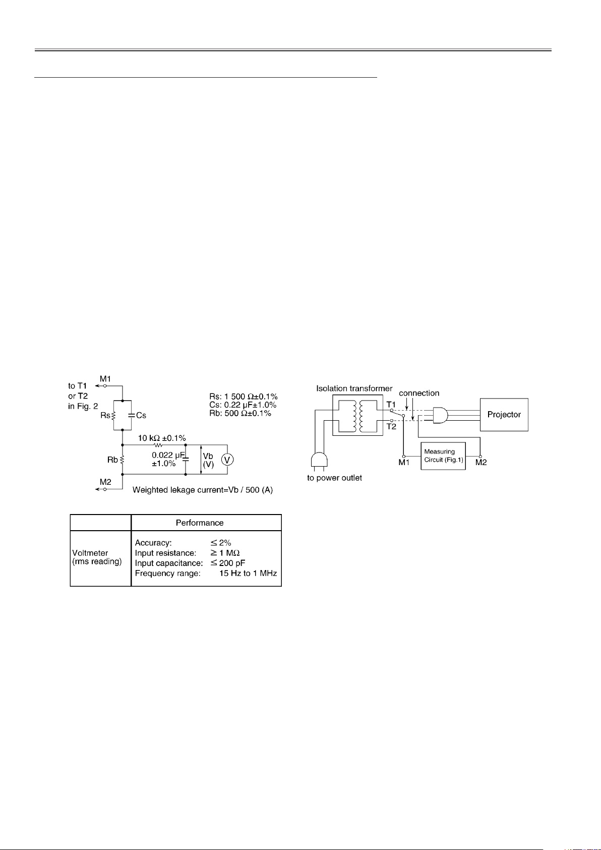
1.2. Leakage Current Check
1. Prepare the measuring circuit as shown in Fig.1.
Be sure to use a voltmeter having the performance described in Table 1.
2. Assemble the circuit as shown in Fig. 2. Plug the power cord in a power outlet.
3. Connect M1 to T1 according to Fig. 2 and measure the voltage.
4. Change the connection of M1 from T1 to T2 and measure the voltage again.
5. The voltmeter must read 0.375 V or lower in both of steps 3 and 4. This means that the current must be 0.75mA or less.
6. If the reading is out of the above standard, the projector must be repaired and rechecked before returning to the customer
because of a possibility of an electric shock.
- For continued safety, no modification of any circuit must be attempted.
- Unplug the power cord from the power outlet before disassembling this projector.
- Use correctly the supplied power cord and must ground it.
- It is advisable to use an isolation transformer in the AC power line before the service.
- Be careful not to touch the rotation part (cooling fan, etc.) of this projector when you service with the upper
case removed and the power supply turned ON.
- Observe the original lead dress during the service. If a short circuit is found, replace all the parts overheated
or damaged by the short circuit.
- After the service, all the protective devices such as insulation barriers, insulation papers, shields, and isolation
R-C combinations must be properly installed.
- After the service, check the leakage current to prevent the customer from getting an electric shock.
1.3. UV Precaution and UHM Lamp Precautions
- Be sure to unplug the power cord from the power outlet when replacing the lamp.
- Because the lamp reaches a very high temperature during its operation, wait until it cools completely when replacing
the Lamp Unit.
- The lamp emits small amounts of UV-radiation, avoid direct-eye contact with the light.
- The lamp unit has high internal pressure. If improperly handled, explosion might result.
- Because the high pressure lamp involves a risk of failure, never touch the lamp wire lead during the service.
Fig. 1
Fig. 2
Table. 2
Safety precautions
-4-
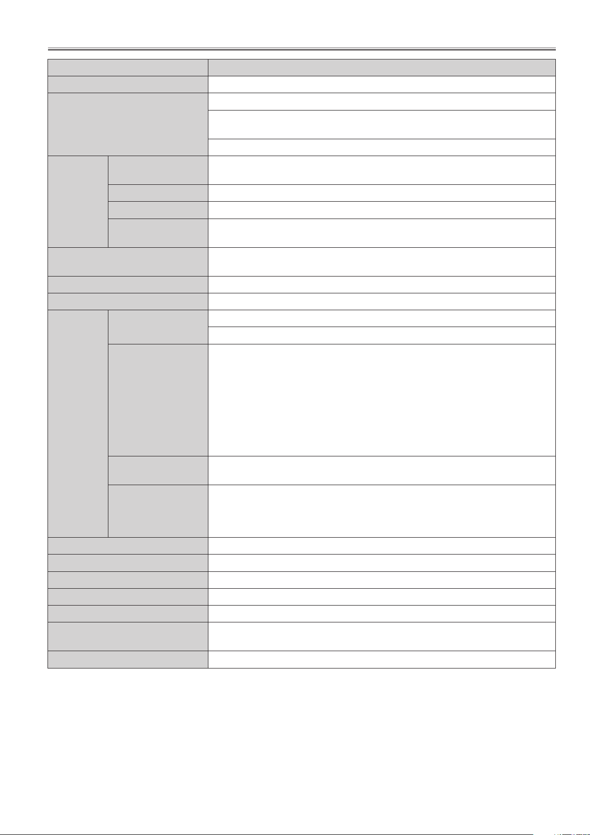
Specifications
Model No. PT-VX400U / E / EA
Power supply AC100 V - 240 V 50 Hz/60 Hz
100 V - 240 V 3.8 A-1.8 A 350 W
Power consumption
Panel size
LCD panel
Lens
Luminous lamp 245 W UHP lamp
Light output *1 4000 lm (ANSI)
A p p l i c a ble scanning frequency *2
Display method 3 transparent LCD panels (RGB)
Drive method Active matrix method
Pixels
for RGB signal
[525i(480i)]
[525p(480p)] Horizontal 31.5 kHz, Vertical 60 Hz
[750(720)/60p] Horizontal 45 kHz, Vertical 60 Hz
[1125(1080)/60i] Horizontal 33.75 kHz, Vertical 60 Hz
for YPBPR signal
[625i(576i)] Horizontal 15.63 kHz, Vertical 50 Hz
[625p(576p)] Horizontal 31.25 kHz, Vertical 50 Hz
[750(720)/50p] Horizontal 37.5 kHz, Vertical 50 Hz
[1125(1080)50i] Horizontal 28.13 kHz, Vertical 50 Hz
• HD/SYNC and V terminals are not compliant with 3 value composite SYNC
When [Standby mode] of [Setting] is set to [ECO]: 0.48W
When [Standby mode] of [Setting] is set to [Network]: 10.0W
When [Standby MIC out] of [Sound] is set to [On]: Max.26 W
1.6 cm(0.63”)
(aspect ratio 4 : 3)
789 432
(1 024 x 768) x 3 panels
Manual zoom (1.6x) / Manual focus
F 1.65 to 2.33, f 15.47 mm to 24.53 mm
Horizontal 15 kHz to 100 kHz, Vertical 50 Hz to 100 Hz
Dot clock frequency: 140 MHz or less
Horizontal 15.75 kHz, Vertical 60 Hz
for Video signal (including S-Video)
525p(480p), 625p(576p), 750(720)/60p, 750(720)/50p, 1125(1080)/60p,
for HDMI signal
Color system 7 (NTSC, NTSC4.43, PAL, PAL-N, PAL-M, SECAM, PAL60)
Projection size 0.76 m-7.62 m(30”-300”)
Screen aspect ratio 4 : 3
Projection scheme Front / Rear / Mount on Ceiling / Floor (Menu setting system)
Speaker 1 (3.7 cm round-type)
Maximum usable volume output
Contrast ratio *1 2000 : 1 (all white / all black)
*1: Measurement, measuring conditions and method of notation all comply with ISO21118 international standards.
*2: For details of video signals that can be projected using this projector, refer to “List of compatible signals”.
Horizontal 15.75 kHz / 15.63 kHz, Vertical 50 Hz / 60 Hz
1125(1080)/50p, 1125(1080)/60i, 1125(1080)/50i
• Displayable resolution: VGA to WUXGA (non-interlace)
• Dot clock frequency: up to 162 MH
10W
-5-
Specifications
Model No. PT-VX400U / E / EA
COMPUTER IN 1
/COMPONENT IN
1 (D-sub 15 pin female)
[RGB signal]
HD/SYNC TTL high impedance, automatic positive/nega-
VD TTL high impedance, automatic positive/negative polar-
[YPBPR signal] Y: 1.0 V [p-p] including synchronization signal, PBPR: 0.7 V
0.7 V [p-p] 75 Ω (When G-SYNC: 1.0 [p-p] 75 Ω
tive polarity compatible
ity compatible
[p-p] 75 Ω
[RGB signal]
HD/SYNC TTL high impedance, automatic positive/nega-
COMPUTER IN 2
/MONITOR OUT
Terminals
VIDEO IN
S-VIDEO IN
HDMI IN 1 (HDMI 19 pin, HDCP and Deep color compatible)
AUDIO IN
AUDIO OUT
CONTROL PORT 1 (D-sub 9 pin, RS-232C compliant, for computer control use
LAN 1 (for RJ-45 network connection, PJLink compatible,)
Power cable length 2.0 m(78 3/4”)
Cabinet Molded plastic
Dimensions
Weight Approx.3.5 kg(7.72 lbs.) *3
VD TTL high impedance, automatic positive/negative polar-
1 (Mini DIN 4 pin, Y 1.0 V [p-p], C 0.286 V [p-p] 75 Ω, S1 signal compatible)
2 (M3 stereo mini jack, 0.5 V [rms], input impedance 22 kΩ and more)
1 (RCA pin jack x 2 (L-R), 0.5 V [rms], input impedance 22 kΩ and more)
0 V [rms] to 2.0 V [rms] valuable, output impedance 2.2 kΩ and less)
0.7 V [p-p] 75
tive polarity compatible
ity compatible
1 (RCA pin jack 1.0 V [p-p] 75 Ω)
1 (M3 stereo mini jack, stereo monitor output compatible,
Height: 97.0 mm (3.82”) (when front adjustable feet shortened)
Depth: 276.9 mm (10.9”) (excluding protractions)
Ω (When G-SYNC: 1.0 [p-p] 75 Ω
Width: 350 mm (13.78”)
Operating environment
Power supply DC 3 V (battery (AAA/R03) x 2)
Remote
control
*3: This is an average value. It may differ depending on individual product.
• The part numbers of accessories and separately sold components are subject to change without notice.
Operating range Approx. 5 m (196.9”) (when operated directly in front of receptor)
Weight 67 g (2.36 ozs.) (including batteries)
Dimensions Width : 52 mm (2.05”), Length : 110 mm (4.33”), Height : 18 mm (0.71”)
Operating environment temperature : 5 °C (41 °F) to 35 °C (95 °F)
Operating environment humidity: 20 % to 80 % (no condensation)
-6-
Circuit Protections
This projector provides the following circuit protections to operate in safety. If the abnormality occurs inside the projector, it will automatically turn off by operating one of the following protection circuits.
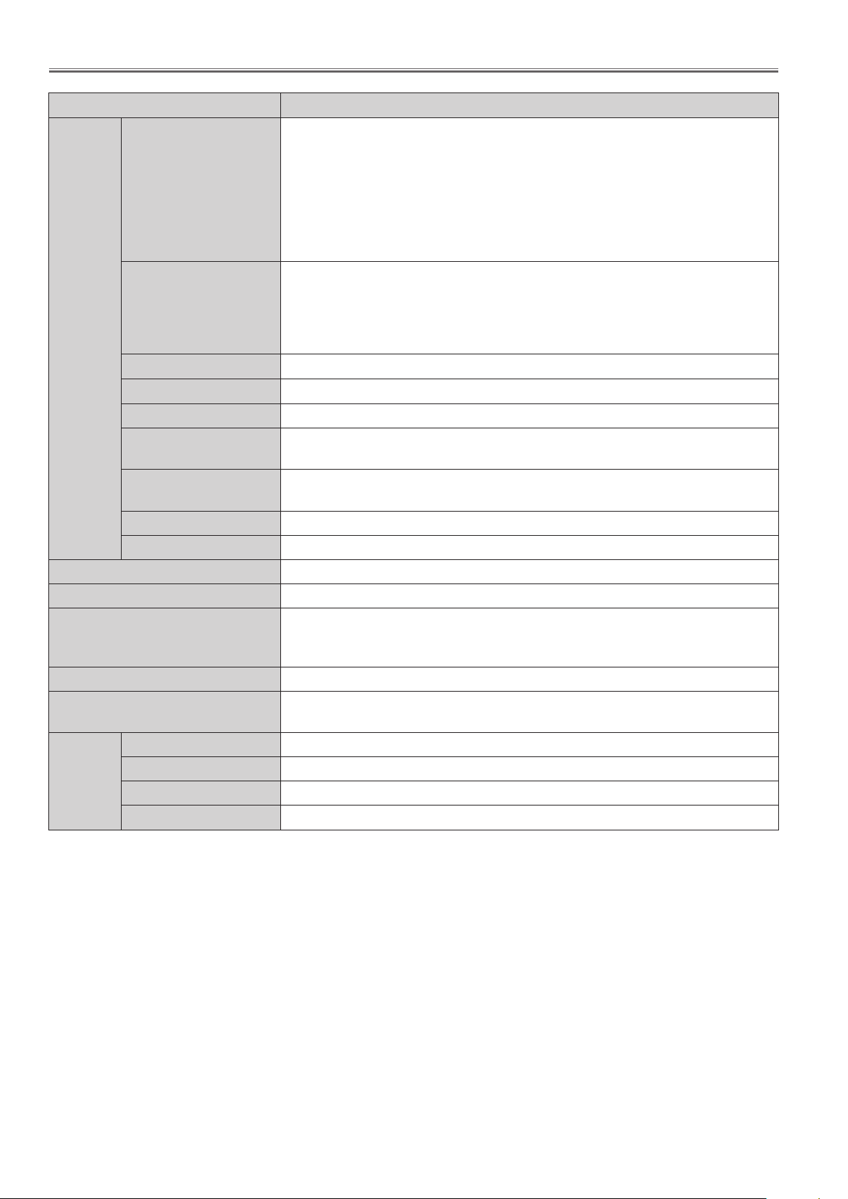
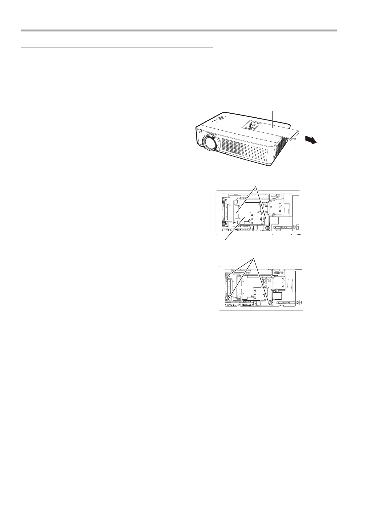
Thermal fuse (SW902)
There is a thermal fuse (SW902) inside of the projector to detect the
internal temperature rising abnormally. When the internal temperature around lamp reaches near 113˚C, the thermal fuse will open to
cut off the power supply to the lamp power circuit.
If the thermal fuse opens, the projector cannot turn on. Thermal
fuse replacement is required.
Thermal fuse (SW902)
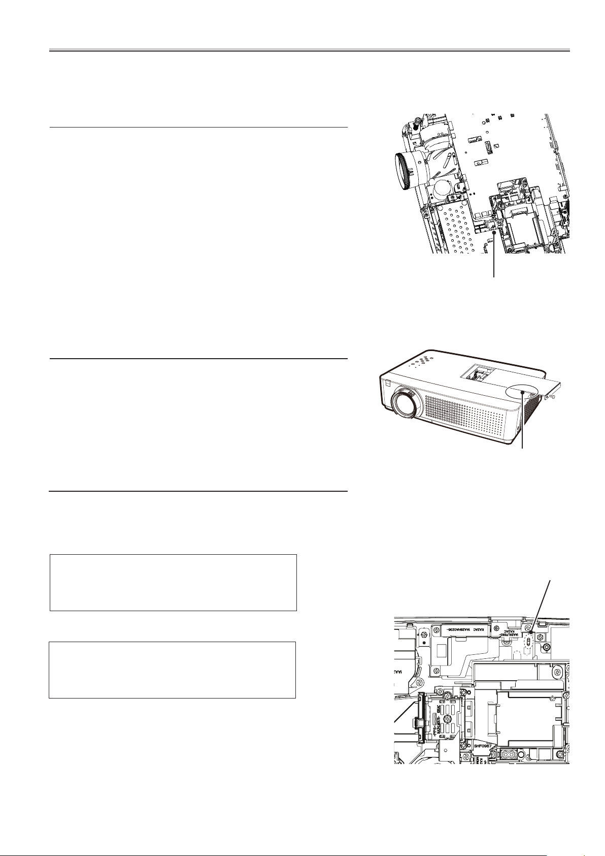
Lamp cover switch (SW901)
The lamp cover switch (SW901) cuts off the drive signal to the lamp
circuit when the lamp cover is removed or not closed completely.
After opening the lamp cover for replacing the lamp assy, place the
lamp cover correctly otherwise the projector can not turn on.
Fuse (F601)
A fuse is located inside of the projector. When the POWER indicator is not lighting, the fuse may be opened. Check the fuse as following steps.
The fuse should be used with the following type;
Fuse Part No.: 323 021 7804
TYPE T6.3AH 250V FUSE
LITTEL
or
FUSE INC. TYPE 21506.3
Lamp cover switch
(SW901)
Fuse
Fuse Part No, : 423 034 4101
TYPE T6.3AH 250V FUSE
Hollyland Co, Ltd. TYPE 50CT063H
How to replace the fuse
1. The fuse is placed on the filter board. Remove the cabinet top
following the "Mechanical Disassembly" .
2. Take the fuse off from the fuse holder, and replace the new one
with the specified type.
-7-

Circuit Protections
Warning temperature and power failure protection
The projector will be automatically turned off when the internal temperature of the projector is abnormally high, or the
cooling fans stop spinning, or the power supplies in the projector are failed.
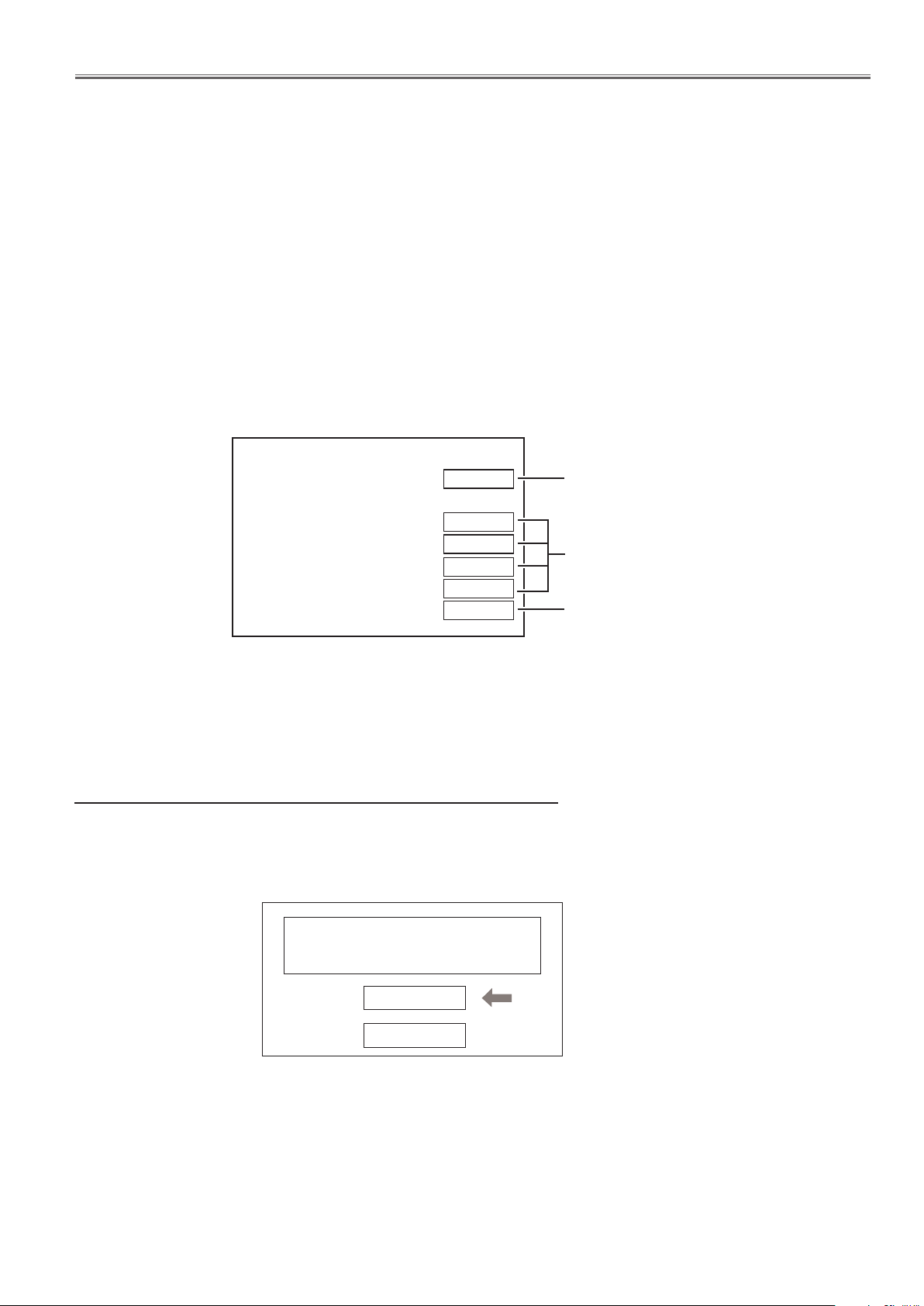
LED indicator
POWER
indicator
WARNING
indicator
The projector is shut down and the WARNING indicator is blinking red.
When the temperature inside the projector reaches a certain level, the projector will be automatically shut down to
protect the inside of the projector and the WARNING and POWER indicators start blinking. When the projector has
cooled down enough (to its normal operating temperature), the POWER indicator stops blinking and lights red, The
projector can be turned on again by pressing the ON/STAND-BY button.
4 Note:
The WARNING indicator continues to blink even after the temperature inside the projector returns to normal. When
the projector is turned on again, the WARNING indicator stops blinking.
Check items
- Remo
- Ventilation slots of the projector are blocked. In such an event, reposition the projector so that ventilation slots are
not obstructed.
- Check if projector is used at higher temperature place (Normal operating temperature is 5 to 35 ˚C or 41 to 95˚F)
ve dust around the air filter.
The projector is shut down and the WARNING indicator lights red.
When the projector detects an abnormal condition, it is automatically shut down to protect the inside of the projector
and the WARNING indicator lights red. In this case, unplug the AC power cord and reconnect it, and then turn the
projector on once again to verify operation.
4 Note:
- If the
and power supply lines referring to the chapter “Power supply & protection circuit” and "Fan control circuit" in the
Chassis Block Diagram section.
WARNING indicator lights red, it may defect the cooling fans or power supply circuits. Check fans operation
WARNING
DO NOT LEAVE THE PROJECTOR WITH THE AC POWER CORD CONNECTED UNDER AN
ABNORMAL CONDITION. IT MAY RESULT IN FIRE OR ELECTRIC SHOCK.
-8-
Maintenance
Air Filter set : ET-RFV100 (Side Filter and Bottom Filter)
* Distribution through commercial channel.
Before replacing the unit
When you perform maintenance or replacement of the parts, make sure to turn off the power and disconnect the
power plug from the wall outlet.
Maintenance
n Outer Case
Wipe off dirt and dust using a soft dry cloth.
• If the dirt is persistent, soak the cloth with water and wring it thoroughly before wiping. Dry off the projector with a
dry cloth.
• Do not use benzene, thinner, or rubbing alcohol, other solvents, household cleaners, or chemical treated dusters.
Using them may cause deterioration of the outer case.
n Front glass surface of the lens
Wipe off the dirt and dust off the front surface of the lens with soft clean cloth.
• Do not use a cloth that has an abrasive surface or a cloth that is moist, oily, or covered with dust.
• Do not use excessive force when wiping the lens as it is fragile.
Attention
The lens is made of glass. Impacts or excessive force when wiping may scratch its surface.
Please handle with care.
n Air filters
Perform the maintenance of the air filter units in following cases. If a “Filter warning” icon appears on the screen,
replace the filters immediately.
• The filter mesh is blocked, causing the filter warning icon appears on the screen and the <WARNING Indicator>
to light in red.
• The filter mesh is blocked, causing the internal temperature to rise, the <POWER Indicator> to light, and the
power to shut off. (When the power is shut off, the <POWER Indicator> blinks in red and the <WARNING Indicator> blinks faster than usual.)
Replacing the unit
Air filter units
Filter prevents dust from accumulating on the optical elements inside the projector. Should the filter become clogged
with dust particles, it will reduce cooling fans’ effectiveness
and may result in internal heat buildup and adversely affect
the life of the projector. If a “Filter warning” icon appears on
the screen, replace the filters immediately.
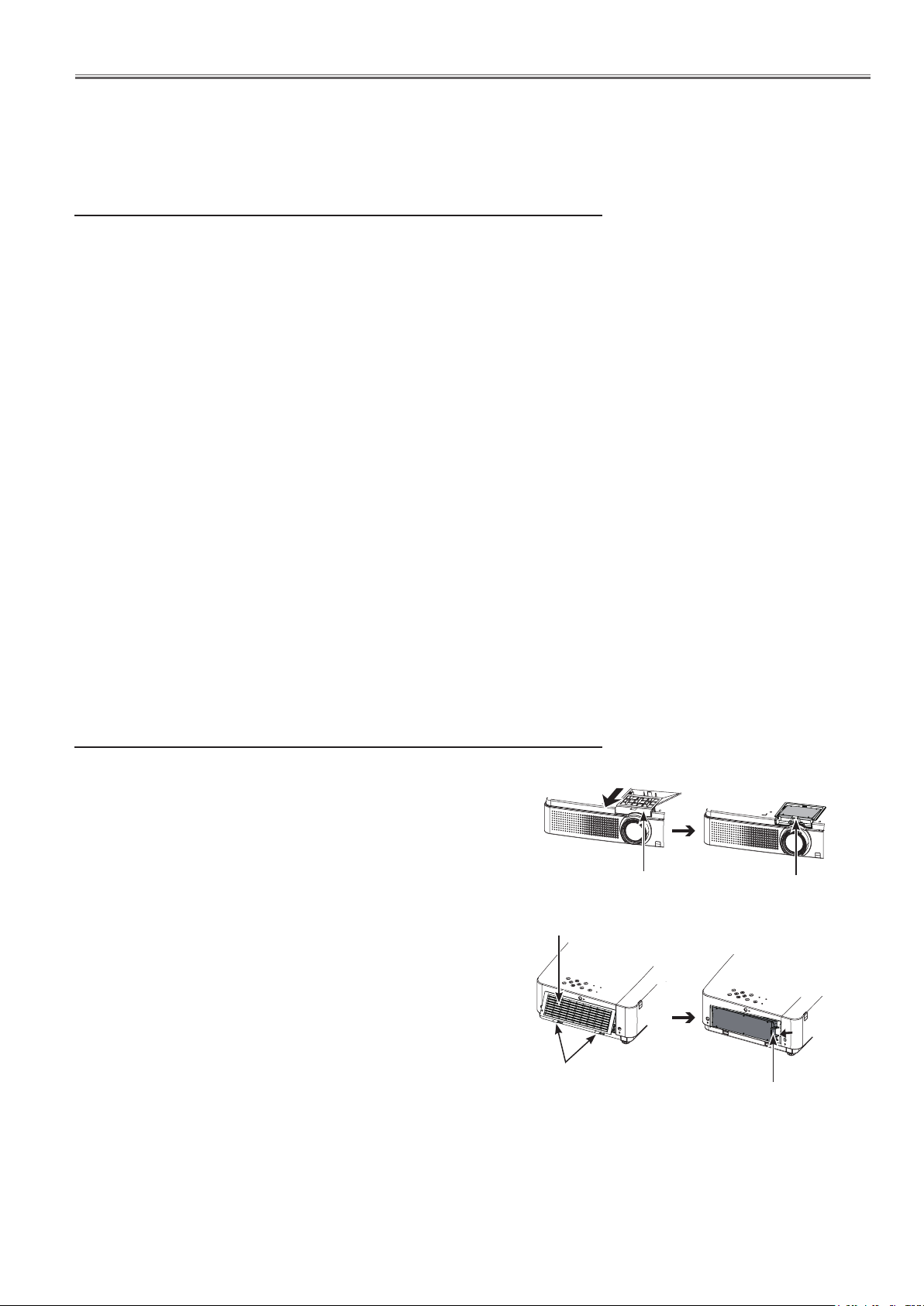
n Replacement of the air filter units
1) Remove the air filters.
• Turn over the projector and pull out the filter cover (bot-
tom); pull up the handle and take out the whole filter
(bottom.)
Press up the latches and pull out the filter cover (side);
pull out the handle and take out the side filter.
2) Replace the air filter units.
• Put new filters back into the position. Make sure that the
filters are fully inserted to the projector.
Filter cover (bottom)
Filter cover (side)
Latches (press up)
Handle (pull up)
Handle (pull up)
-9-
Maintenance
n Filter counter reset
After replacing the filter, be sure to reset the filter counter.
1) Press st to select [Filter counter reset].
2) Press the <SELECT> button.
[Filter counter Reset?] appears. Select Yes to con-
tinue. Another confirmation dialog box appears, select
Yes to reset the Filter counter.
Attention
urn off the power before you replace the air filter unit.
• T
• When attaching the air filter unit, make sure that the
projector is stable, and work in an environment that is
safe, even in the event of the air filter unit dropping.
• Do not operate the projector with the filters removed.
Dust may accumulate on the optical elements degrading picture quality.
• Do not put anything into the air vents. Doing so may
result in malfunction of the projector.
• Do not wash the filters with water or any other liquid
matter. Otherwise the filters may be damaged.
n Attaching the filter cover to the projector
The supplied filter cover is designed for preventing dust accumulation on the filter when mounting the projector on
the ceiling.
1) Turn over the projector.
2) Remove the filter cover (bottom).
3) Attaching the filter cover (supplised) to the projector.
4) Attach the projector to the ceiling mount in accordance with the instruction manuals which come with
the ceiling mount.
Attention
• Please keep the filter cover (bottom) for later use.
• If the Projector Mount Base (ET-PKV100B) is applied, the
supplied filter cover is unnecessary.
To ceiling mount
Filter cover
(suppiesed)
-10-

Maintenance
LAMP
n Lamp unit
The lamp unit is a consumable component. You can check the total usage time using Lamp runtime in the Information
menu.
It is recommended to ask an authorized engineer to replace the lamp unit. Contact your dealer.
Consult your dealer to purchase a replacement lamp unit (ET-LAV100, dealt as a service parts).
CAUTION:
n Do not replace the lamp unit when it is hot. (Wait at least 45 minutes after use.)
The inside of the cover can become very hot, take care to avoid burn injuries.
n Notes on the replacement of the lamp unit
• The luminous source of the lamp is made of glass and may burst if
you hit it against a hard surface or drop it.
Please handle with care.
• A Phillips screwdriver is required for replacement of the lamp unit.
• When replacing the lamp unit, be sure to hold it by the handle. Hold
the lamp unit horizontally while replacing it to prevent fragments of
glass from scattering, in case the lamp breaks. When the projector
is mounted on a ceiling, do not work directly under the projector or
put your face close to the projector. Pull the old lamp unit out horizontally.
• The lamp contains mercury. Consult your local municipality or your
dealer about correct disposal of used lamp units.
Attention
• Do not use other than designated lamp units.
• The part numbers of accessories and separately sold components are subject to change
without notice
n When to replace the lamp unit
When the projection lamp of the projector reaches its end of life, the Lamp replacement icon appears on the screen
and LAMP REPLACE indicator lights yellow. Replace the lamp with a new one promptly.
The message is displayed for 10 seconds. If
Over 3000 hours
Over 3200 hours
Note
•
Allow a projector to cool enough before you open the lamp cover. The inside of the projector can become very hot.
• The Lamp replacement icon will not appear when the display function is set to Off, or during Freeze, or AV mute.
you press any button within the 10 seconds,
the message disappears.
After ten minutes, the projector shuts off the
power automatically
On screen
Lamp replacement icon
LAMP REPLACE indicator
Lights in yellow (even in stand-by
mode).
-11-
Maintenance
Replacing the lamp unit
CAUTION:
• When the projector is mounted on a ceiling, do not work with your face close to the projector.
• Attach the lamp unit and the lamp cover securely.
• When you experience difficulty in installing the lamp, remove it and try again. If you use force to install the lamp, the
connector may be damaged.
1) Turn off the projector. Unplug the AC power cord.
Wait at least 45 minutes and make sure the lamp unit
and surroundings are cool.
2) Use a Phillips screwdriver to loosen the lamp cover
fixing screw and remove the lamp cover.
• Remove the lamp cover by pulling it slowly toward the
direction of the arrow.
3) Use a Phillips screwdriver to loosen the lamp unit
fixing screws until the screws turn freely. Hold the
used lamp unit by its handles, and pull it gently from
the projector.
4) Insert the new lamp unit in correct direction. Tighten
the three lamp unit fixing screws securely with a
Phillips screwdriver
5) Attach the lamp cover, and tighten the lamp cover
fixing screw securely with a Phillips screwdriver.
Note
• When you replace the new lamp unit, the projector resets
the total usage time of the lamp unit automatically.
Lamp cover
Lamp cover
fixing screw
Handle
Lamp
Lamp unit fixiing screws
-12-
Maintenance
Counter
Projector 850H
Lamp
Auto 200H
Normal 150H
Eco1 250H
Eco2 250H
Corresponding value 610H
The LAMP REPLACE indicator will light yellow when the total lamp used time (Corresponding value) reaches 3,000
hours. This is to indicate that lamp replacement is required. The total lamp used time is calculated by using the
below expression.
Total lamp used time (Corresponding value) = Tnormal + Teco x 0.67 + Tauto x k*
Tnormal : used time in the normal mode
Teco : used time in the eco1 and eco2 mode
Tauto : used time in the auto mode
* Factor k is changed from 0.67 to 1.0 automatically depending on the input signal
You can check the lamp used time following to the below procedure.
1 Press and hold the ON/STAND-BY button on the projector or the remote control for more than 20 seconds.
2 The projector used time and lamp used time will be displayed on the screen briefly as follows.
Projector used time
Cumulative
lamp operating
time in each
mode.
Total lamp used time
Warning message on the non-standard lamp used
If the non-standard lamp is used, the warning and confirmation messages will appear on the screen every startup.
Some of the functions are limited when the non-standard lamp is used in spite of the warning.
Since the lamp is not standard,
projector failed to read lamp data.
Continue to use this lamp?
Yes
No
-13-

Maintenance
Cleaning
After long periods of use, dust and other particles will accumulate on the LCD panel, prism, mirror, polarized
glass, lens, etc., causing the picture to darken or color to blur. If this occurs, clean the inside of optical unit.
Remove dust and other particles using air spray. If dirt cannot be removed by air spray, disassemble and clean
the optical unit.
Cleaning with air spray
Remove the cabinet top following to “Mechanical Disassembly”. Clean up the LCD panel and polarizing plate by
using the air spray from the cabinet top opening.
Caution:
Use a commercial (inert gas) air spray designed for cleaning camera and computer equipment. Use a resin-based
nozzle only. Be very careful not to damage optical parts with the nozzle tip. Never use any kind of cleanser on the
unit. Also, never use abrasive materials on the unit as this may cause irreparable damage.
Disassembly Cleaning
Disassembly cleaning method should only be performed when the unit is considerable dirty and cannot be
sufficiently cleaned by air spraying alone.
Be sure to readjust the optical system after performing disassembly cleaning.
1. Remove the cabinet top and main units following to “Mechanical Disassembly”.
2. Remove the optical base top following to “Optical Unit Disassembly”. If the LCD panel needs cleaning, remove
the LCD panel unit following to “LCD panel replacement”.
3. Clean the optical parts with a soft cloth. Clean extremely dirty areas using a cloth moistened with alcohol.
Caution:
The surface of the optical components consists of multiple dielectric layers with varying degrees of refraction. Never
use organic solvents (thinner, etc.) or any kind of cleanser on these components.
Since the LCD panel is equipped with an electronic circuit, never use any liquids (water, etc.) to clean the unit. Use
of liquid may cause the unit to malfunction.
Cleaning the projection lens
Unplug the AC power cord before cleaning.
Gently wipe the projection lens with a cleaning cloth that contains a small
amount of non-abrasive camera lens cleaner, or use a lens cleaning paper or
commercially available air blower to clean the lens.
Avoid using an excessive amount of cleaner. Abrasive cleaners, solvents, or
other harsh chemicals might scratch the surface of the lens.
Cleaning the projector cabinet
Unplug the AC power cord before cleaning.
Gently wipe the projector body with a soft dry cleaning cloth. When the cabinet
is heavily soiled, use a small amount of mild detergent and finish with a soft dry
cleaning cloth. Avoid using an excessive amount of cleaner. Abrasive cleaners,
solvents or other harsh chemicals might scratch the surface of the cabinet.
When the projector is not in use, put the projector in an appropriate carrying
case to protect it from dust and scratches.
-14-
Security Function Notice
This projector provides security functions such as "Key lock", "PIN code lock" and "Logo PIN code lock". When the
projector has set these security function on, you are required to enter correct PIN code to use the projector. If you
do not know the correct PIN code to the projector, the projector can no longer be operated or started. In this case,
you must reset those function first according to the resetting procedure described below and then check up on the
projector.
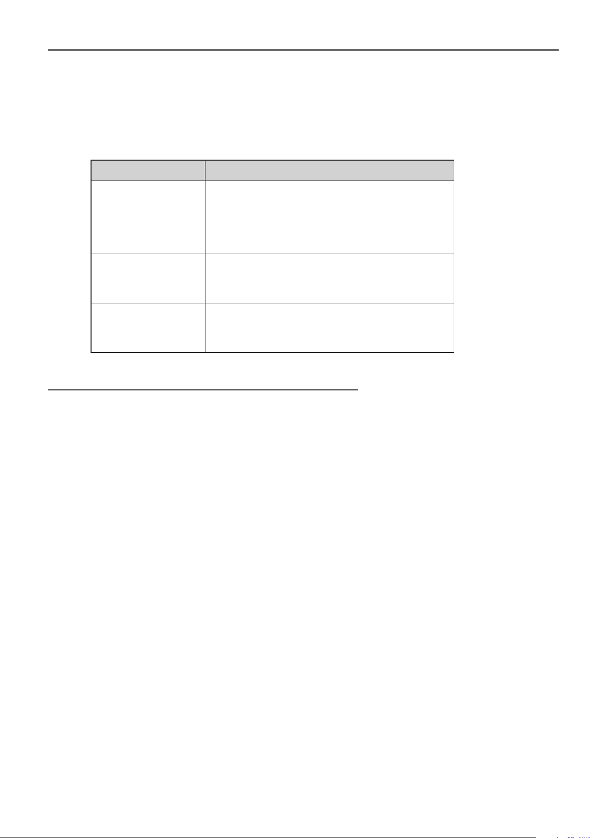
Function Description
Locks operation of the top control or the remote control.
Key lock
PIN code lock
Logo PIN code lock
If the Key lock is enabled with top control lock, the projector can no longer be started.
Initial setting: Key lock function is disabled
Prevents the projector from being operated by an unauthorized person.
Initial code: “1234”
Prevents an unauthorized person for changing the
start-up logo on the screen.
Initial code: “4321”
Resetting procedure
1 Disconnect the AC power cord from the AC outlet.
2. As pressing the SELECT button, connect the AC power cord into an AC outlet again.
3. Keep pressing the SELECT button and then press the ON/STAND-BY button.
4. Release the ON/STAND-BY button first and then release the SELECT button.
- The PIN code lock and Logo PIN code lock will be reset as the initial PIN code at the factory and
the key lock function is disabled.
Please refer to the owner's manual for further information of the security functions.
-15-
Standby Mode Notice
This projector provides 2 types of standby mode, Eco standby and Network standby. According to the standby mode
"Eco" or "Network", several functions are restricted as shown in the table below. To change the standby mode, use
the projector's menu "Setting".
Network .......... Supply the power to the network function even after turning off the projector. You can turn on/ off the
projector via network, modify network environment, and receive an e-mail about projector status
while the projector is powered off.
Eco ................. Select “Eco” when you do not use the projector via network. The projector’s network function will
stop when turning off the projector.
When "Eco" is selected, several functions will be restricted.
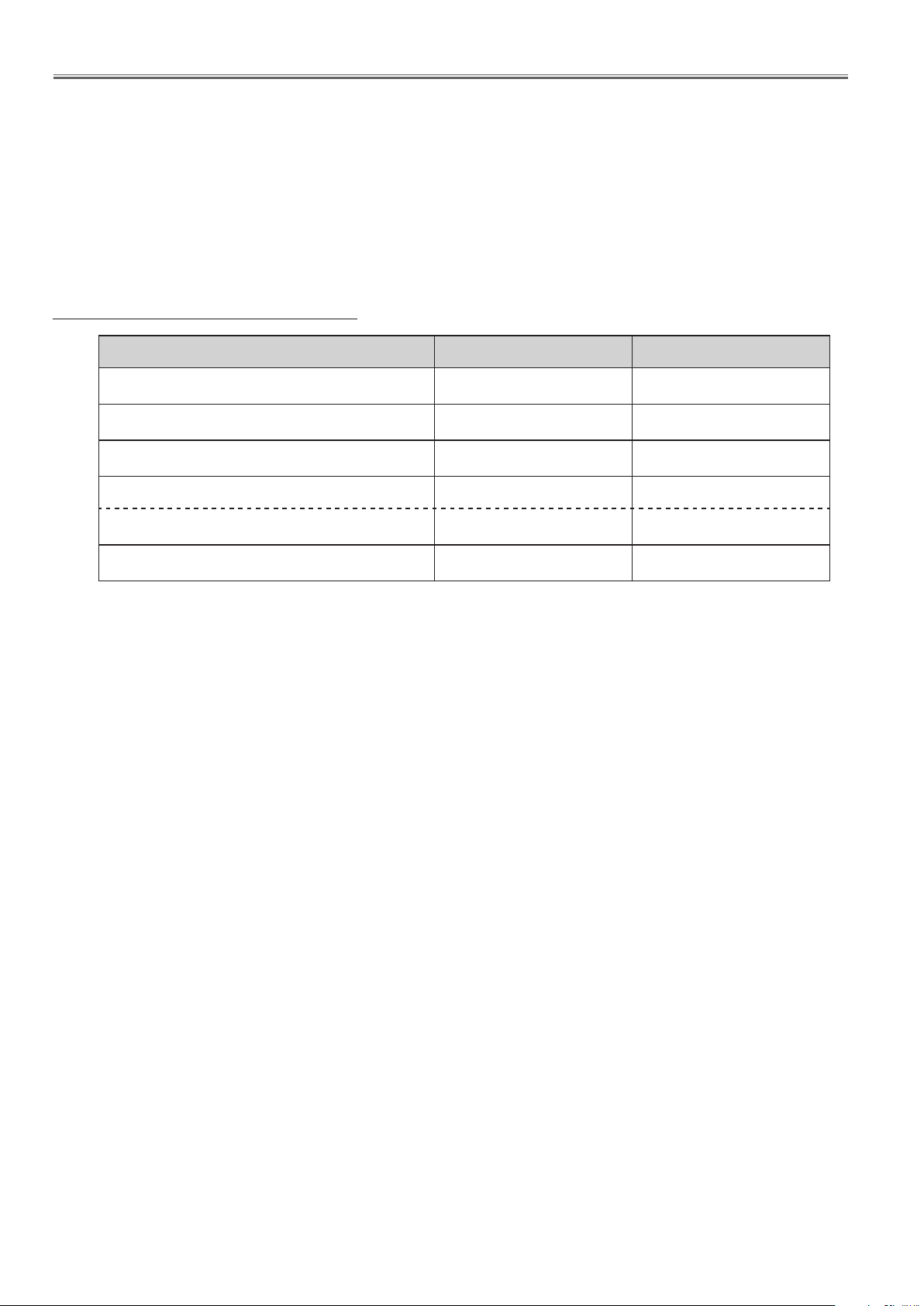
Restricted Function in the standby mode
Function Eco Network
*1
Serial command control
4
4
Network Function
Monitor Out
Audio Out
Mic Out (MIC Volume)
Direct on
*1 Effective only power-on command.
*2 MIC volume can be output when the Standby MIC Out function is set to On.
--
--
-- --
--
4 4
4
4
4
*2
-16-
Mechanical Disassembly
Mechanical disassembly should be made following procedures in numerical order.
Following steps show the basic procedures, therefore unnecessary step may
be ignored.
Caution:
The parts and screws should be placed exactly the same position as the original
otherwise it may cause loss of performance and product safety.
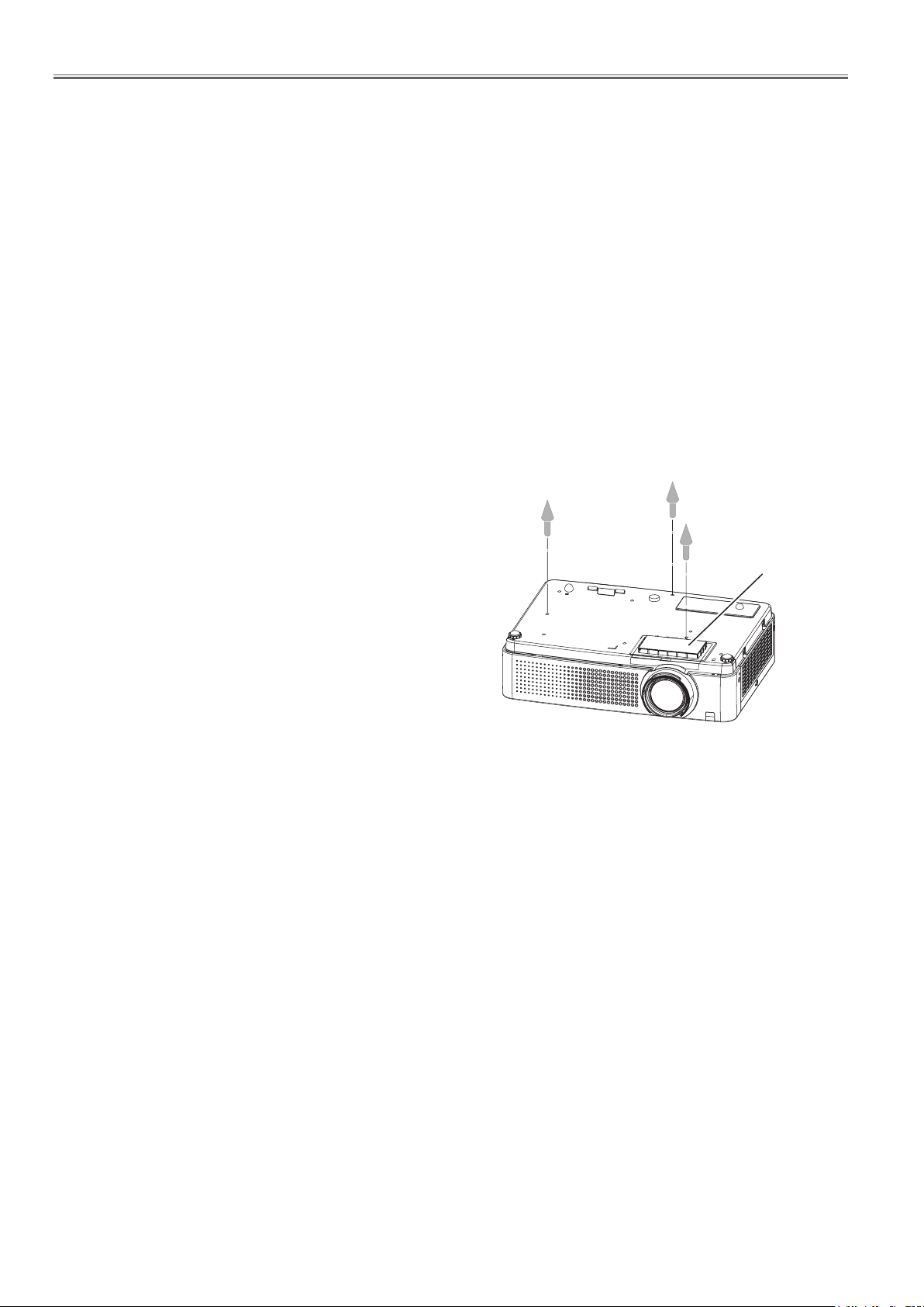
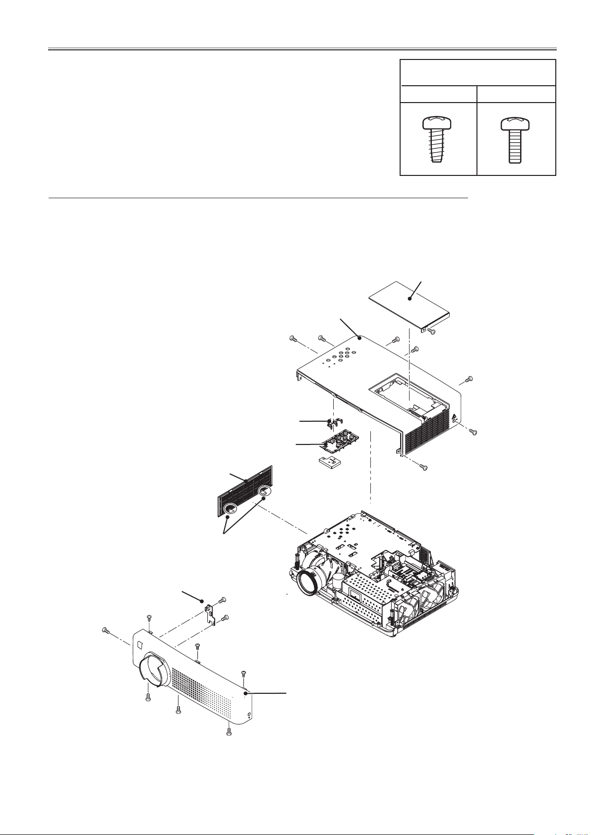
1. Cabinet top, cabinet front removal
1. Pull up two latches to take off the filter cover(side).
2. Loosen 1 screw-A to remove the lamp cover.
3. Remove 6 screws-B (M3x8) and 1 screw C-(M3x8) to remove the cabinet top.
4. Remove 4 screws-D (M3x8) and 3 screws-E (T3x8) to remove the cabinet front.
Cabinet top
B
B
B
Screws expression
(Type Diameter x Length) mm
T type M Type
Lamp cover
A
C
B
Dec inlay LED
Control buttons
Filter cover(side)
Latches
RC board
D
D
F(T3x8)x2
F
D
B
B
D
E
E
E
Cabinet front
Fig.1
-17-

Mechanical Disassembly
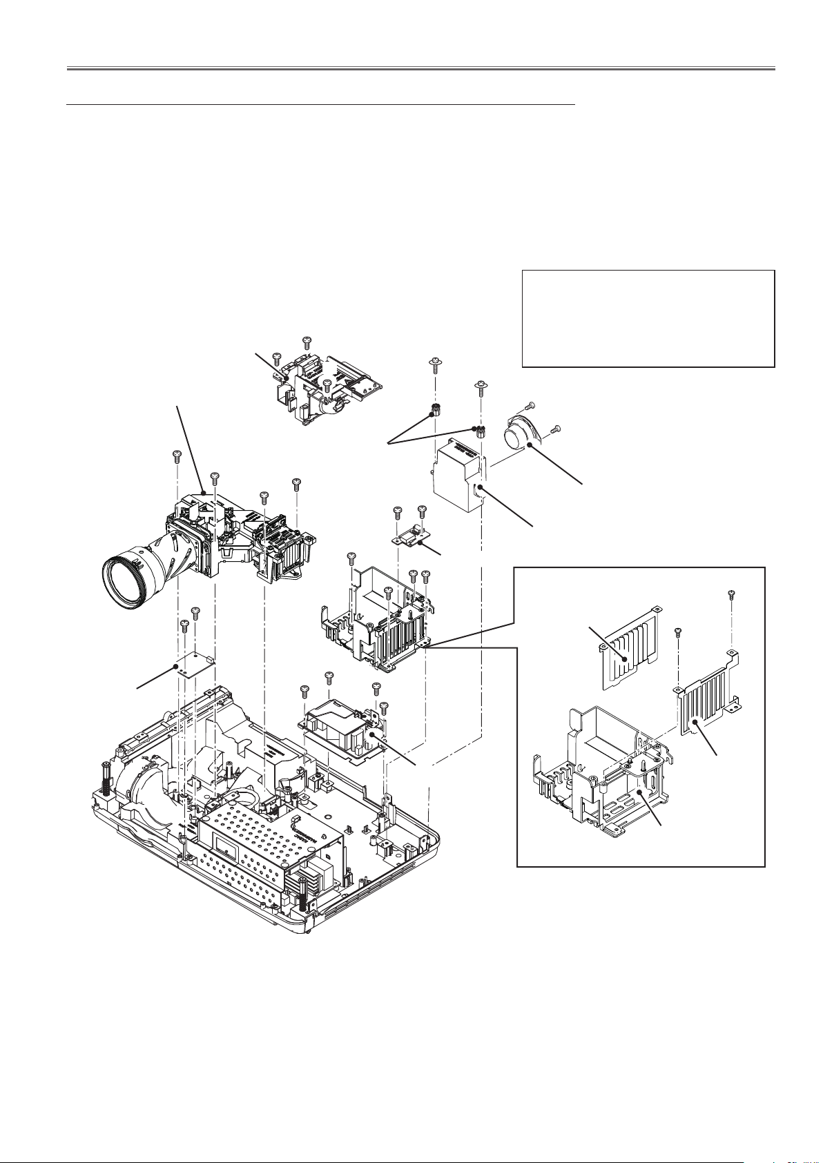
2. Main board, AV board and fans(FN904 and FN905) removal
1. Remove 3 screws-A (T3x8) to remove the fans (FN904 and FN905).
2. Remove 3 screws-B (M2.5x6) and 2 screws-C (M3x8) to remove the main
board assy.
3. Release the hooks to remove the AV panel, remove 3 screws-D (T3x6) and
2 hex screws E to remove the AV board.
B
B
B
AV panel
SW901
Stopper
Main board
C
A
FN904
D
E
E
Hooks
D
D
C
AV board
A
A
Fan holder
FN905
Fan shield
-18-
Label side
Fig.2
Mechanical Disassembly
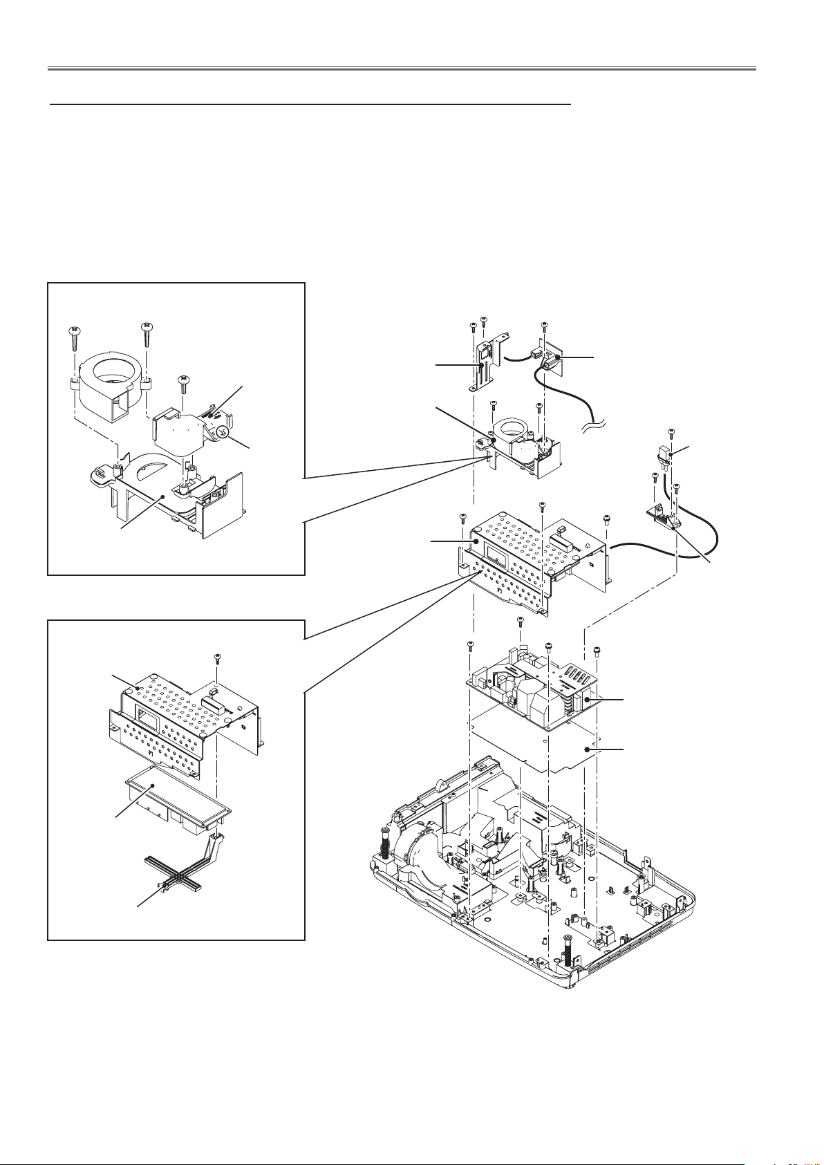
3. Speaker(SP901), lamp assy(LP900), optical unit removal
1. Remove the 2 screws-A(T3x12) to remove the speaker holder. Remove the 2
screws-B(T3x8) to remove the speaker(SP901).
2. Loosen 3 screws-C to remove the lamp assy (LP900).
3. Remove 4 screws-D (T3x8) to remove the optical unit.
4. Remove 3 screws-E (T3x8) and 1 screw-F(M3x8) to remove the lamp holder.
Remove 2 screws-G(T3x6) to remove the ID connect board.
5. Remove 2 screws-H(T3x8) to remove the sub power board.
6. Remove 3 screws-K (M3x8) and 1 screw-J (T3x8) to remove the AC filter board.
Note:
When removing screws-G which is to
fix the ID connect board, the special
screwdriver is needed as the below;
Star screwdriver Size: T10
B
Speaker
(SP901)
Optical Unit
D
Lamp assy
(LP900)
D
C
C
C
Bushes
D
D
G
A
A
G
B
Sub power
board
H
E
E
E
H
K
K
J
K
AC Filter board
ID connect board
F
Speaker holder
Inside light
shield
(T3x8)x2
Outside
light shield
Lamp
holder
-19-
Fig.3
Mechanical Disassembly
4. Fan (FN906) , thermal fuse (SW902) and power board removal
1. Remove 2 screws-A (T3x8) to remove the cabinet front holder. Remove 1 screw-B
(T3x8) to remove the thermal fuse (SW902).
2. Remove 2 screws-C(T3x8) to remove the lamp fan duct assy.
3. Remove 1 screw-D (T3x8) and 2 screws-E (T3x8) to remove the lamp socket and
socket plug.
4. Remove 2 screws-F (T3x8) and 1 screw-G (M3x8) to remove the ballast board &
shield assy.
5. Remove 2 screws-H (T3x8) and 2 screws-J (M3x8) to remove the power board.
(T3x12)x2
FN906
Lamp fan holder
Shield
T3x8
Lamp fan duct
2 hooks
T3x8
Cabinet front holder
Lamp fan duct assy
Ballast board &
shield assy
A
A
F
H
H
B
Thermal fuse
(SW902)
C
C
D
Lamp
socket
E
F
J
G
J
Power board
E
Socket plug
Ballast board
Ballast holder
Insulation sheet
Fig.4
-20-
Mechanical Disassembly
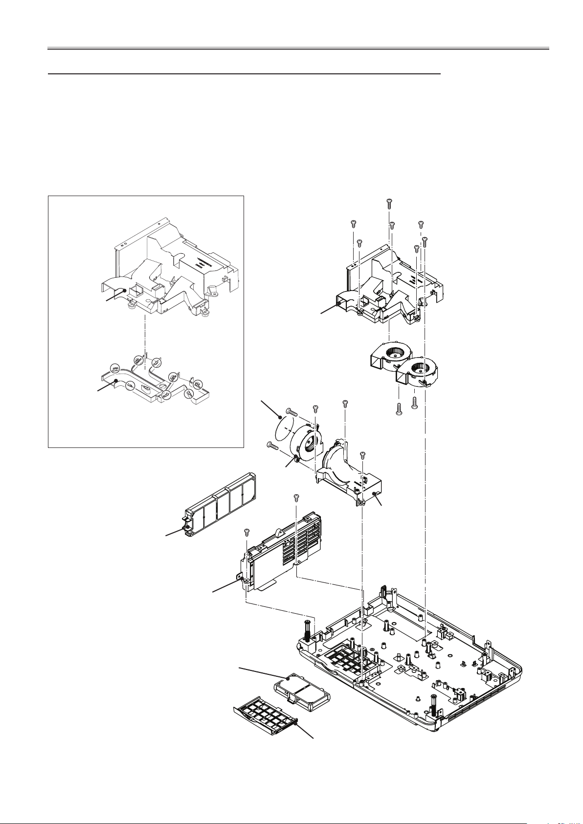
5. Mounting duct, fans(FN901, FN902, FN903) removal
1. Remove 5 screws-A (T3x8) and 2 screws-B (T3x12) to remove the panel mounting duct assy.
2. Remove 2 screws-C (T3x12) to remove fans (FN902 and FN903).
3. Remove 3 screws-D (T3x8) to remove the filter mounting duct and remove 2 screws-E(T3x12)
to remove fan (FN901).
4. Take out the filter box(side), and then remove 2 screws-F(T3x8) to remove the side filter holder.
5. Take off the filter box(bottom) and filter cover(bottom).
B (T3x12)x2
Panel mounting duct top and bottom removal
Panel mounting
duct top
Hooks
Panel mounting
duct assy
A (T3x8)x5
FN902
A
A
A
A
B
FN903
Panel mounting
duct bottom
Unhook the 8 hooks to removal the
panel mounting duct top and bottom.
Filter box(side)
Side filter holder
Filter box(bottom)
Fan spacer
F
E
E
FN901
F
D
D
C
C
D
Filter
mounting
duct
Filter cover(bottom)
-21-
Fig.5
Mechanical Disassembly
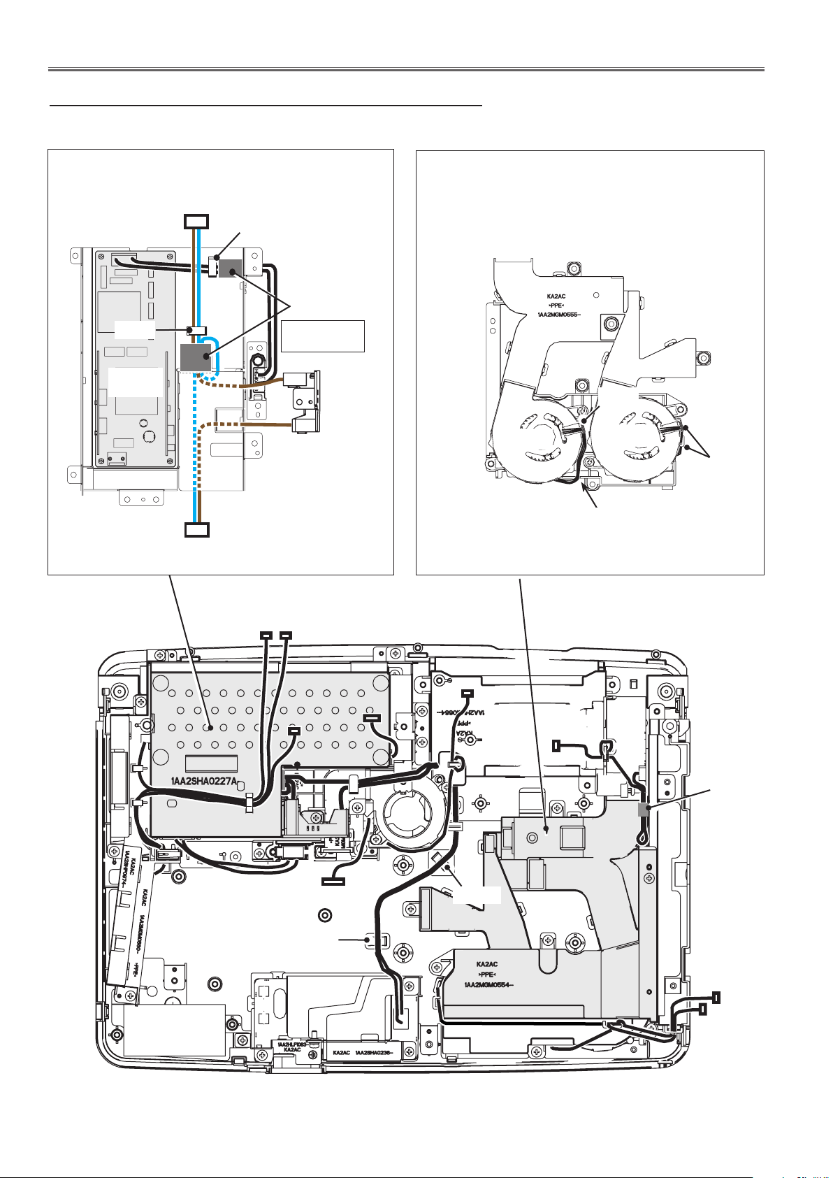
6. Cable reforming
Reform cables as shown below.
Bottom view of the power box
To POWER BOARD
Hook
Hook
BALLAST
BOARD
To AC FILTER BOARD
Ferrite core
Fix the ferrite
core here.
SW902
Bottom view of the panel mounting duct top
Hook
FN902
FN903
Wires pass through
the slit.
Hook
Guide
Tape
Guide
Fig.6
-22-
Optical Parts Disassembly
Before taking this procedure, remove Cabinet Top and Main Board following to the “Mechanical Disassembly”.
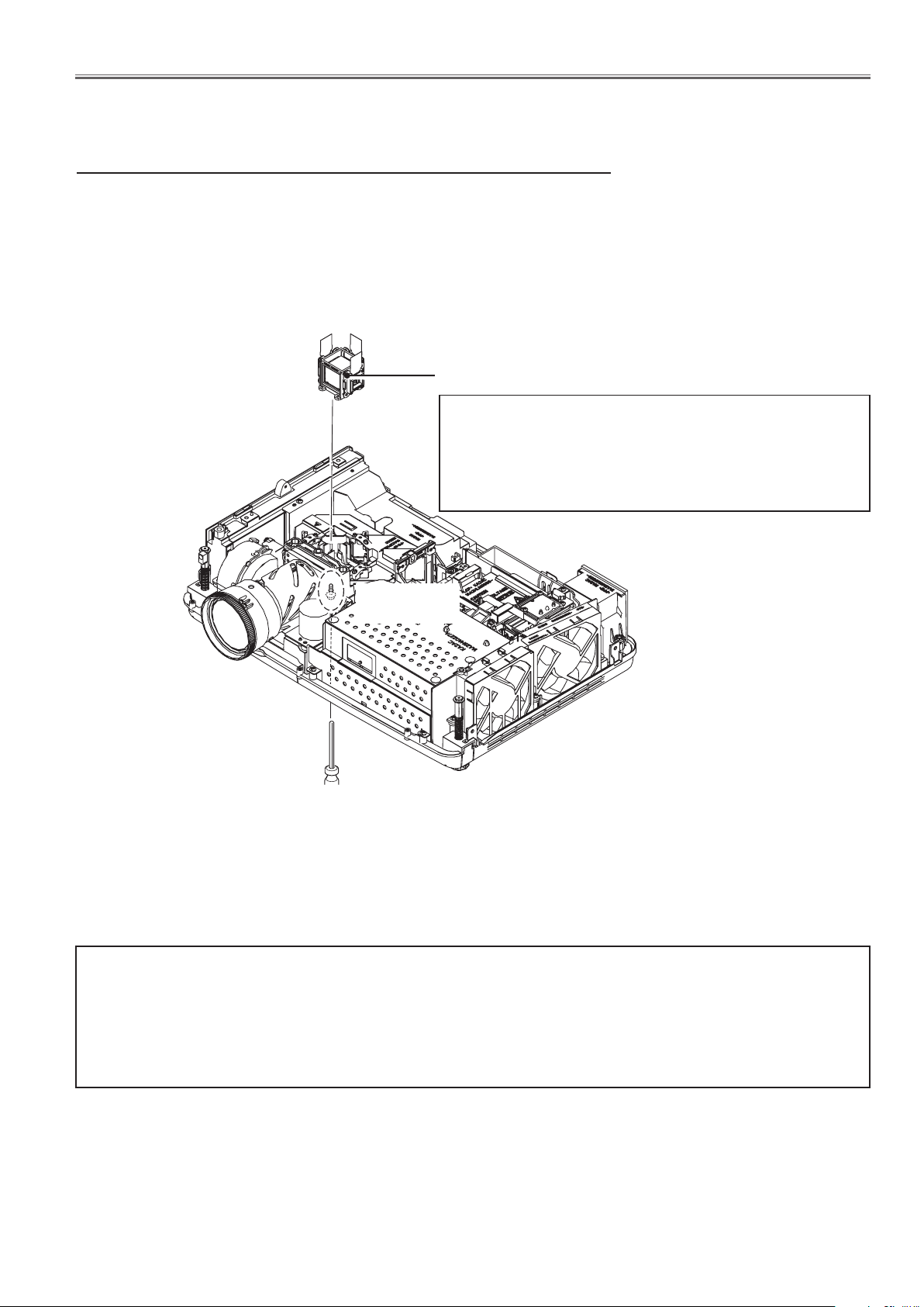
Disassembly requires a 2.0mm hex wrench.
1. LCD panel/prism assy removal
1. Loosen 1 screw (M3x10) from the cabinet bottom side and take the LCD
panel/prism assy upward off.
LCD panel/
prism assy
*Note on handling the LCD panel/prism assy
LCD panel, polarized glasses are very sensitive parts.
Never touch or wipe the surface. When removing the dust
on the surface, use a commercial (inert gas) air spray to
remove them.
(M3x10)
(Bottom side)
Fig.1
IMPORTANT NOTICE on LCD panel/prism assy replacement
LCD panels used for this model cannot be replaced separately. Do not disassemble the LCD panel/prism assy.
These LCD panels are installed with precision at the factory. When replacing the LCD panel, should be replaced
whole of the LCD panels and prism assy at once.
When replacing LCD panel/prism assy, take the optical and electrical adjustments following to the chapter "Adjustment".
-23-
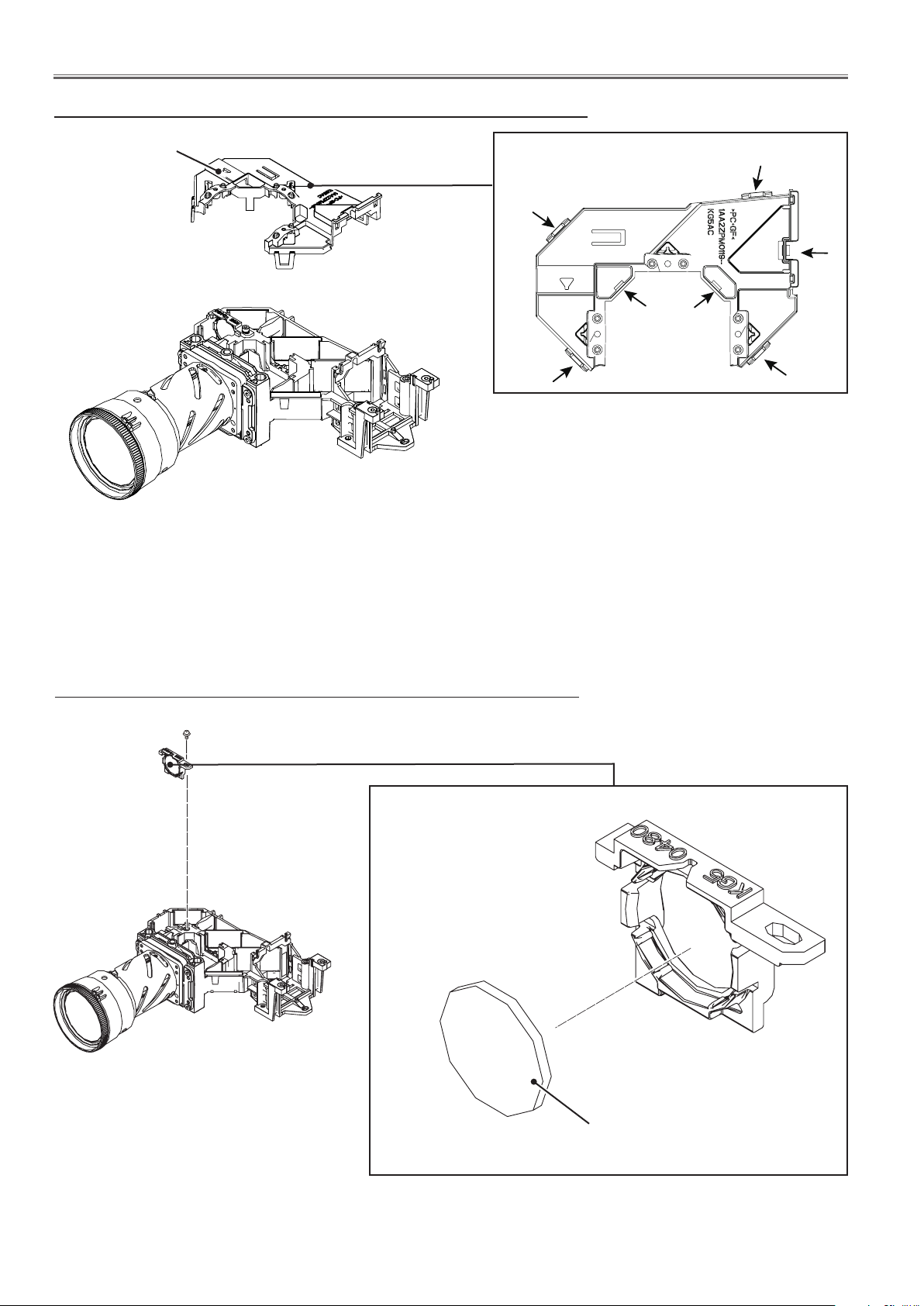
Optical Parts Disassembly
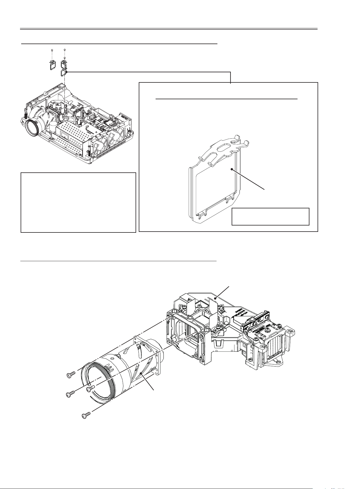
2. Polarized glass(IN) assy removal
(M2.5x6)x1
Polarized glass(IN) assy
Fig.2
*Note on handling the polarized glass
B-Polarized glass-in is very sensitive parts.
Never touch or wip e th e surface. G ra b the
mounting base when handling the polar ized
glass assy. When removing the dust on the
surface, use a commercial (inert gas) air spray
to remove them. Never use organic solvents.
Note on mounting the Polarized glass(IN) assy
When mounting the R-Polarized glass(IN) assy and
B-Polarized glass(IN) assy, make sure that mounting position
of the holder should be center.
Polarized glass(IN)
*Polarized glass is not removed
from the mounting base.
3. Projection lens removal
Note: The optical unit should be removed from the cabinet bottom before
removing the projection lens.
Projection lens
(M2.5x8)x4
Optical unit
Fig.3
-24-
Optical Parts Disassembly
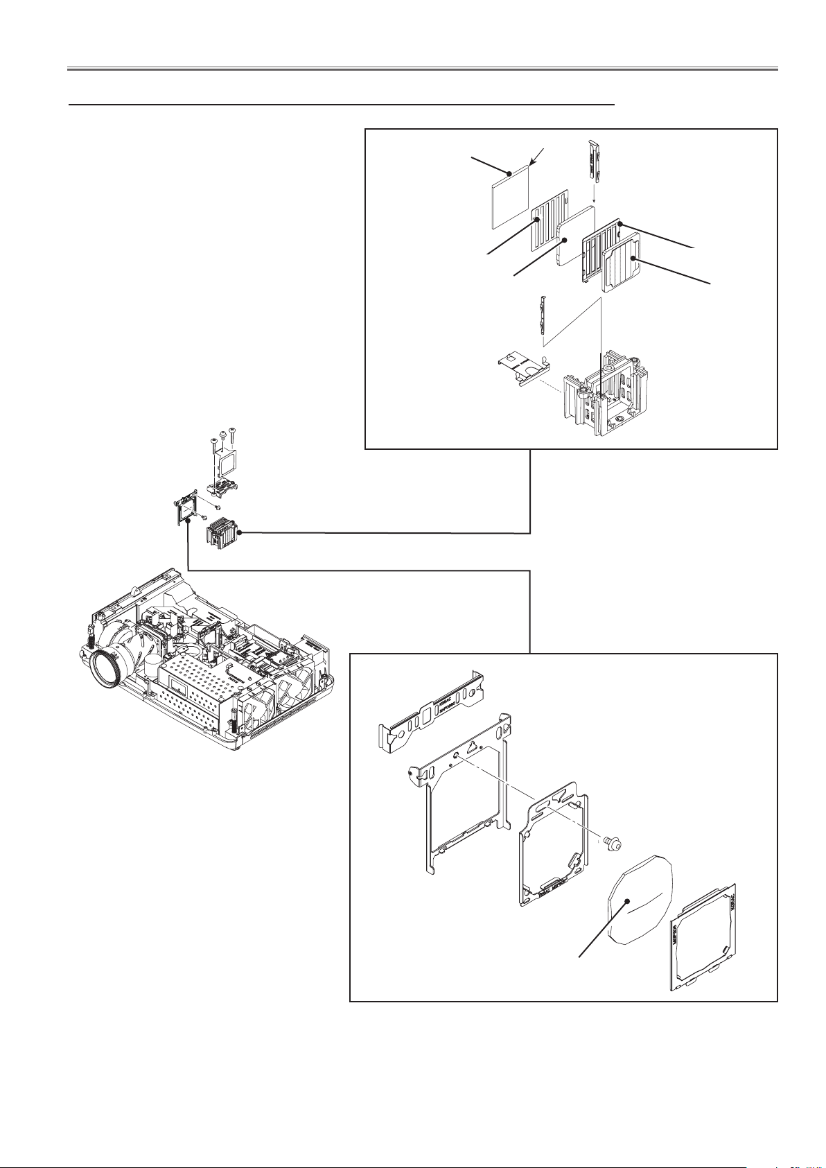
4. Integrator and condenser lens (OUT) disassembly
M(2.5x6)
(M3x14)x2
(M2.5x6)x2
Prism Beam Splitter
(PBS)
Light mask PBS
Integrator lens (OUT)
* Rugged surface
facing to the PBS
Integrator lens assy
Marker
Light mask
Integrator lens-in
* Rugged surface fac-
ing to the lamp.
Condenser lens (OUT) assy
M(2.5x6)
Fig.4
Condenser lens (OUT)
-25-
Optical Parts Disassembly
5. Optical unit top removal
Optical top
Unhook 7 hooks to remove the Optical Unit Top.
Fig.5
6. Relay lens removal
M(2.5x6)
Fig.6
Relay lens assy
Relay lens
-26-
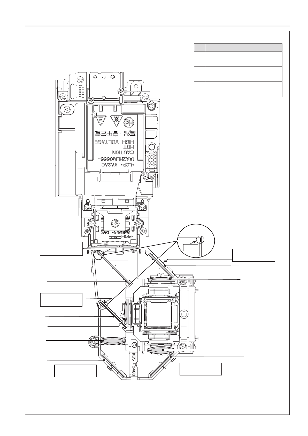
Optical Parts Disassembly
7. Locations and directions
When mounting or assembling the optical parts in the optical unit, the parts must be mounted in the specified location and direction as shown in figure below.
No. Parts Name
1 Dichroic mirror (B)
2 Dichroic mirror (G)
3 Condenser lens (G)
4 Mirror (R)
5 Relay lens (IN)
6 Mirror (B)
Marker comes this
side up
1
Marker comes this
side up
2
3
5
4
Marker comes this
side
Marker
Marker comes this
side
6
3
5
4
Marker comes this
side
Fig.7
-27-
Servicing Notice
Note on main board replacement
Take the following workings when the main board is replaced.
Adjustment data setting
This projector stores "Color shading correction data" and "Gamma correction data" in the memory IC (IC801) on the
main board. Those adjustment data have been setup according to the optical characteristics of the mounted LCD
panels preciously in the factory. When replacing the main board, you need to read out the those setting data stored in
the memory IC on the previous main board and write down them into the memory IC on the new main board. By this
way, it enables the projector to reproduce the picture which has properly adjusted color shading correction, gamma
correction. For further details, refer to the operation manual of the software [PROJECTOR SERVICE TOOL v4.20].
Serial number setting
The data of serial number is stored in both memory ICs (IC1371) and (IC1051) on the main board. "Serial number"
displayed on the on-screen menu "Information" is stored in the memory IC (IC1371). The serial number for EDID is
stored in the memory IC (IC1051).
After replacing the main board, perform the work below to restore the serial number.
Use the serial no. setting tool to write the correct serial no. referring to the serial no. (S/N) printed on the rating label.
•
For further details, refer to the operation manual of the software [SERIAL NO. SETTING TOOL v1.00].
• It is impossible to rewrite the serial number stored in the memory IC (IC1051), remove it on the previous main board
and replace it on the new main board.
The projector service tool v.4.20 and serial no. setting tool v1.00 can be downloaded from the projector service web site.
Model no. setting
The data of projector's model no. is stored in both memory ICs (IC1371) and (IC1051) on the main board. The model
number displayed on on-screen menu is stored in the memory IC (IC1371). The model number for EDID is stored in
the memory IC (IC1051). After replacing the main board, perform the work below to restore the model number.
• 1. Enter the service mode.
2. Select the Group "430 ~ 437" and No. "1", change the Data value from "0" to "10". Refer to table below. The Data
value will return to "0" after setting.
3. To check the setting, select each Group and No. "0" and check its value with table below.
How to enter the service mode, or set the Group. No. and Data, refer to the item "Service adjustment menu opera-
tion".
• It is impossible to rewrite the model number stored in the memory IC (IC1051), remove it on the previous main board
and replace it on the new main board.
Model no. setting
Model no. setting Group No. Data
Not defined 430
PT-VX400 431
PT-VX400U 432
PT-VX400E 433
PT-VX400EJ 434
PT-VX400EA 435
PT-VX400EAJ 436
PT-BX40 437
0
1 0 -> 10
0
1 0 -> 10
0
1 0 -> 10
0
1 0 -> 10
0
1 0 -> 10
0
1 0 -> 10
0
1 0 -> 10
0
1 0 -> 10
[ (refer t table right)
[ (refer t table right)
[ (refer t table right)
[ (refer t table right)
[ (refer t table right)
[ (refer t table right)
[ (refer t table right)
[ (refer t table right)
Model no. chanking
Data Model no.
0 Not defined
1 PT-VX400
2 PT-VX400U
3 PT-VX400E
4 PT-VX400EJ
5 PT-VX400EA
6 PT-VX400EAJ
7 PT-BX40
-28-
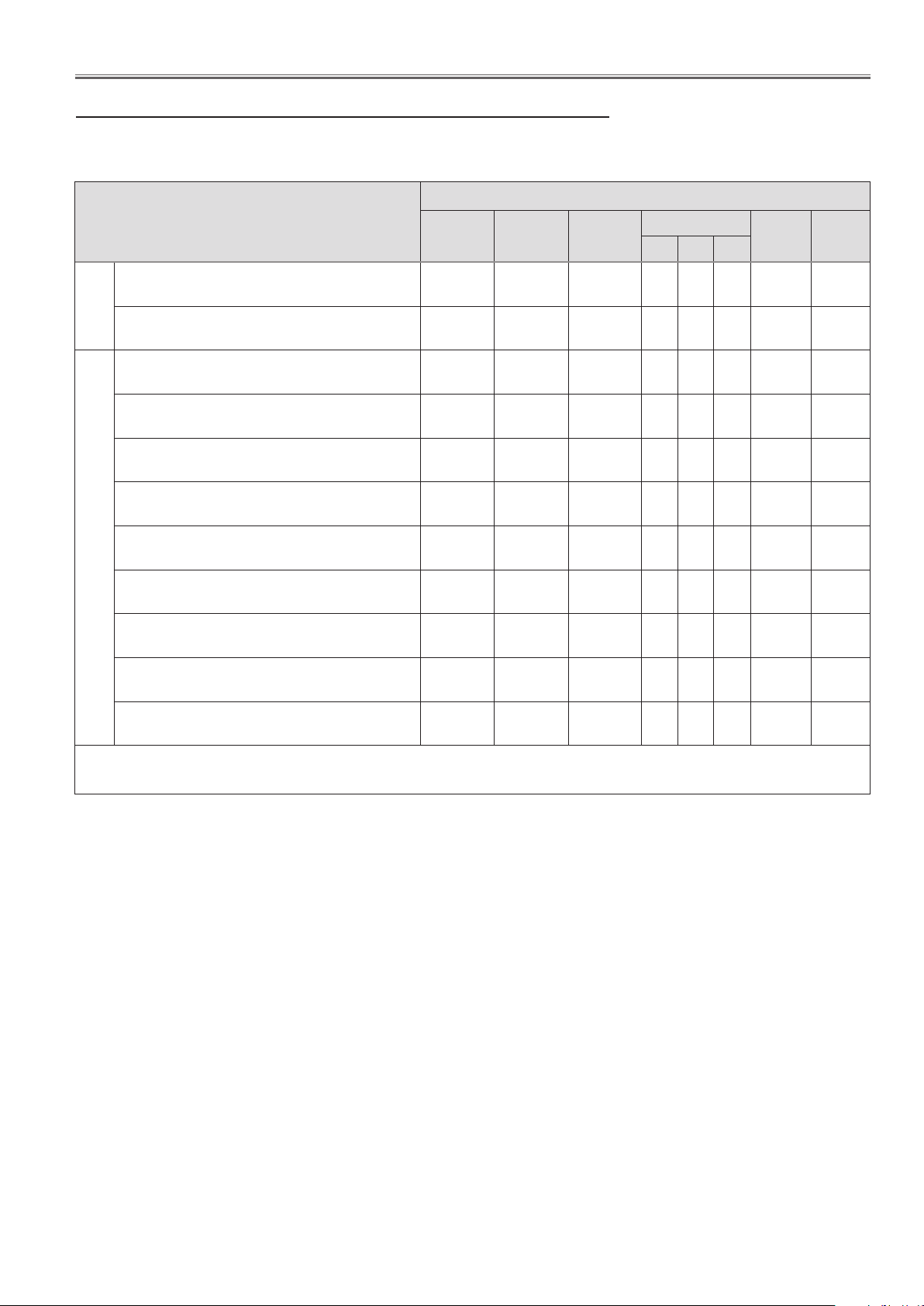
Adjustments
Adjustments after parts replacement
Adjustments
Optical
Contrast adjustment
: Adjustment necessary ❍ : Check necessary
●
Disassembly / Replaced parts
LCD/
prism assy
❍ ●
Condenser
lens (OUT)
Relay
lens (OUT)
Polarized glass
R G B
Power
board
Main
board
Optical center adjustment
Fan voltage adjustment
❍ ● ●
● ●
Auto calibration adjustment [PC]
Auto calibration adjustment [Component]
Electrical Adjustments
Auto calibration adjustment [Video]
Common center adjustment
Gamma correction adjustment *
White balance adjustment
Color shading correction adjustment *
● ●
● ●
❍ ❍
❍ ❍ ❍ ❍ ❍
Keystone offset adjustment
* To setup or adjust those items, the Projector Service Tool v. 4.20 software is needed. Refer to the owner's
manual for this software for the further details.
❍
❍
❍
●
-29-

Optical Adjustments
A
Slot B
Before taking optical adjustments below, remove the cabinet top following to the “Mechanical Disassembly”.
Adjustments require a 2.0mm hex wrench and a slot screwdriver.
Note: Do not disconnect connectors on the main board, because the projector cannot turn on due to operate the
power failure protection.
WARNING : USE UV RADIATION EYE AND SKIN PRO-
TECTION DURING SERVICING
CAUTION: To prevent suffer of UV radiation, those
adjustment must be completed within 25
minutes.
Contrast adjustment
[Before Adjustment]
- Input a 100% of black raster signal.
1 Loosen a screw A (Fig.1) on the G-polarized glass mounting
base.
2 Adjust the slot B to obtain the darkest brightness on the screen by
using a slot screwdriver.
3 Tighten the screw A to fix the G-polarized glass mounting base.
- This adjustment should be performed in the darkest room to improve
the precision of adjustment.
Fig.1
-30-
 Loading...