

Panasonic PT-VW431DEA Operating Instruction

Operating Instructions
Functional Manual
LCD Projector
Model No.
Commercial Use
PT-VW431DEA
Thank you for purchasing this Panasonic Product.
J
Before operating this product, please read the instructions carefully, and save this manual
for future use.
J
Before using your projector, be sure to read “Read this rst!” (
pages 2 to 8).
Æ
ENGLISH
LL4SC
Read this rst!
Information
Important
WARNING: THIS APPARATUS MUST BE EARTHED.
WARNING: To prevent damage which may result in re or shock hazard, do not expose this appliance to rain
Machine Noise Information Ordinance 3. GSGV, January 18, 1991: The sound pressure level at the operator
position is equal or less than 70 dB (A) according to ISO 7779.
WARNING:
1. Remove the plug from the mains socket when this unit is not in use for a prolonged period of time.
2. To prevent electric shock, do not remove cover. No user serviceable parts inside. Refer servicing to
3. Do not remove the earthing pin on the mains plug. This apparatus is equipped with a three prong earthing
CAUTION: To assure continued compliance, follow the attached installation instructions, which includes
TURN OFF THE UV LAMP BEFORE OPENING THE LAMP COVER.
or moisture.
qualied service personnel.
type mains plug. This plug will only t an earthing-type mains socket. This is a safety feature. If you are
unable to insert the plug into the mains socket, contact an electrician. Do not defeat the purpose of the
earthing plug.
using the provided power cord and shielded interface cables when connecting to computer or
peripheral device. If you use serial port to connect PC for external control of projector, you must
use commercial RS-232C serial interface cable with ferrite core. Any unauthorized changes or
modications to this equipment will void the user’s authority to operate.
WARNING:
WARNING: TO REDUCE THE RISK OF FIRE OR ELECTRIC SHOCK, DO NOT EXPOSE THIS PRODUCT
TO RAIN OR MOISTURE.
2
- ENGLISH

Read this rst!
13A250V
BS1363/A
HE-8
N
ASA
L
IMPORTANT: THE MOULDED PLUG (U.K. only)
FOR YOUR SAFETY, PLEASE READ THE FOLLOWING TEXT CAREFULLY.
This appliance is supplied with a moulded three pin mains plug for your safety and convenience. A 13 amp fuse
is tted in this plug. Should the fuse need to be replaced, please ensure that the replacement fuse has a rating
of13 amps and that it is approved by ASTA or BSI to BS1362.
Check for the ASTA mark or the BSI mark on the body of the fuse.
If the plug contains a removable fuse cover, you must ensure that it is retted when the fuse is replaced. If you
lose the fuse cover, the plug must not be used until a replacement cover is obtained. A replacement fuse cover
can be purchased from an Authorised Service Center.
If the tted moulded plug is unsuitable for the mains socket in your home, then the fuse should be
removed and the plug cut off and disposed of safely. There is a danger of severe electrical shock if the
cut off plug is inserted into any 13 amp socket.
If a new plug is to be tted, please observe the wiring code as shown below.
If in any doubt, please consult a qualied electrician.
WARNING: THIS APPLIANCE MUST BE EARTHED.
IMPORTANT: The wires in this mains lead are coloured in accordance with the following code:
Green - and - Yellow: Earth
Blue: Neutral
Brown: Live
Important
Information
As the colours of the wire in the mains lead of this appliance may not correspond with the coloured markings
identifying the terminals in your plug, proceed as follows.
The wire which is coloured GREEN - AND - YELLOW must be connected to the terminal in the
plug which is marked with the letter E or by the Earth symbol or coloured GREEN or GREEN AND - YELLOW.
The wire which is coloured BLUE must be connected to the terminal in the plug which is marked
with the letter N or coloured BLACK.
The wire which is coloured BROWN must be connected to the terminal in the plug which is
marked with the letter L or coloured RED.
How to replace the fuse: Open the fuse compartment with a screwdriver and replace the fuse.
ENGLISH -
3

Read this rst!
4
- ENGLISH
Important
Information
WARNING:
The wall outlet or the circuit breaker shall be installed near the equipment and shall be easily
accessible when problems occur. If the following problems occur, cut off the power supply
immediately.
Continued use of the projector in these conditions will result in re or electric shock.
During a thunderstorm, do not touch the projector or the cable.
Electric shocks can result.
Do not do anything that might damage the power cord or the power plug.
If the power cord is used while damaged, electric shocks, short-circuits or re will result.
Insert the power plug securely into the wall outlet.
If the plug is not inserted correctly, electric shocks or overheating will result.
Clean the power plug regularly to prevent it from becoming covered in dust.
Failure to observe this will cause a re.
Do not handle the power plug with wet hands.
Failure to observe this will result in electric shocks.
Do not overload the wall outlet.
If the power supply is overloaded (ex., by using too many adapters), overheating may occur and re will result.
POWER
If foreign objects or water get inside the projector, cut off the power supply.
z
If the projector is dropped or the cabinet is broken, cut off the power supply.
z
If you notice smoke, strange smells or noise coming from the projector, cut off the power supply.
z
Please contact an Authorized Service Center for repairs, and do not attempt to repair the projector yourself.
Do not damage the power cord, make any modications to it, place it near any hot objects, bend it
z
excessively, twist it, pull it, place heavy objects on top of it or wrap it into a bundle.
Ask an Authorized Service Center to carry out any repairs to the power cord that might be necessary.
Do not use anything other than the provided power cord.
z
Do not use the provided power cord for other electrical equipment.
z
Do not use plugs which are damaged or wall outlets which are coming loose from the wall.
z
If dust builds up on the power plug, the resulting humidity can damage the insulation.
z
If not using the projector for an extended period of time, pull the power plug out from the wall outlet.
z
Pull the power plug out from the wall outlet and wipe it with a dry cloth regularly.
ON USE/INSTALLATION
Do not place liquid containers on top of the projector.
If water spills onto the projector or gets inside it, re or electric shocks will result.
If any water gets inside the projector, contact an Authorized Service Center.
Do not place the projector on soft materials such as carpets or sponge mats.
Doing so will cause the projector to overheat, which can cause burns, re or damage to the projector.
Do not set up the projector in humid or dusty places or in places where the projector may come into
contact with oily smoke or steam, ex. a bathroom.
Using the projector under such conditions will result in re, electric shocks or components deterioration.
Components deterioration (such as ceiling mount brackets) may cause the projector which is mounted on the
ceiling to fall down.
Do not install this projector in a place which is not strong enough to take the full weight of the
projector or on top of a surface which is sloped or unstable.
Failure to observe this will cause projector to fall down or tip over the projector, and severe injury or damage
could result.
Do not place another projector or other heavy objects on top of the projector.
Failure to observe this will cause the projector to become unbalanced and fall, which could result in damage or
injury. The projector will be damaged or deformed.

Read this rst!
ENGLISH -
5
Important
Information
WARNING:
Installation work (such as ceiling mount bracket) should only be carried out by a qualied technician.
If installation is not carried out and secured correctly it can cause injury or accidents, such as electric shocks.
Do not use anything other than an authorized ceiling mount bracket.
z
Be sure to use the wire provided with the projector mount base for ceiling mount as an extra safety
z
measure to prevent the projector from falling down. (Install in a different location to the ceiling mount
bracket.)
Do not cover the air inlet port or the air outlet port.
Doing so will cause the projector to overheat, which can cause re or damage to the projector.
Do not place the projector in narrow, badly ventilated places.
z
Do not place the projector on cloth or papers, as these materials could be drawn into the air inlet port.
z
Do not place your hands or other objects close to the air outlet port.
Doing so will cause burns or damage your hands or other objects.
Heated air comes out of the air outlet port. Do not place your hands or face, or objects which cannot
z
withstand heat close to this port.
Do not look and place your skin into the lights emitted from the lens while the projector is being used.
Doing so can cause burns or loss of sight.
Strong light is emitted from the projector’s lens. Do not look or place your hands directly into this light.
z
Be especially careful not to let young children look into the lens. In addition, turn off the power and
z
disconnect the power plug when you are away from the projector.
Do not insert any foreign objects into the projector.
Doing so will cause re or electric shocks.
Do not insert any metal objects or ammable objects into the projector or drop them onto the projector.
z
Never attempt to remodel or disassemble the projector.
High voltages can cause re or electric shocks.
For any inspection, adjustment and repair work, please contact an Authorized Service Center.
z
Do not project an image with the lens cover attached.
Doing so can cause re.
Do not allow metal objects, ammable objects, or liquids to enter inside of the projector. Do not allow
the projector to get wet.
Doing so may cause short circuits or overheating, and result in re, electric shock, or malfunction of the
projector.
Do not place containers of liquid or metal objects near the projector.
z
If liquid enters inside of the projector, consult your dealer.
z
Particular attention must be paid to children.
z
Use the ceiling mount bracket specied by Panasonic.
Defects in the ceiling mount bracket will result in falling accidents.
Attach the supplied safety cable to the ceiling mount bracket to prevent the projector from falling down.
z
Wiring work of LAN cables for DIGITAL LINK should only be carried out by a qualied technician.
Doing so will cause poor quality image or sound on account of imperfect work.

Read this rst!
6
- ENGLISH
Important
Information
WARNING:
Do not use or handle the batteries improperly, and refer to the following.
Failure to observe this will cause burns, batteries to leak, overheat, explode or catch re.
Do not allow children to reach the batteries (AAA/R03 or AAA/LR03 type).
If the battery uid leaks, do not touch it with bare hands, and take the following measures if necessary.
Do not disassemble the lamp unit.
If the lamp breaks, it could cause injury.
Lamp replacement
The lamp has high internal pressure. If improperly handled, an explosion and severe injury or accidents will
result.
Do not allow infants or pets to touch the remote control unit.
Do not use the supplied power cord with devices other than this projector.
Remove the depleted batteries from the remote control promptly.
ACCESSORIES
Do not use unspecied batteries.
z
Do not disassemble dry cell batteries.
z
Do not heat the batteries or place them into water or re.
z
Do not allow the + and
z
necklaces or hairpins.
Do not bring or store batteries together with metallic objects.
z
Store the batteries in a plastic bag and keep them away from metallic objects.
z
Make sure the polarities (+ and
z
Do not use a new battery together with an old battery or mix different types of batteries.
z
Do not use batteries with the outer cover peeling away or removed.
z
Remove the empty batteries from the remote control at once.
z
Insulate the battery using tape or something similar before disposal.
z
The battery can cause personal injury if swallowed.
z
If swallowed, seek medical advice immediately.
z
Battery uid on your skin or clothing could result in skin inammation or injury.
z
Rinse with clean water and seek medical advice immediately.
Battery uid coming in contact with your eyes could result in loss of sight.
z
In this case, do not rub your eyes. Rinse with clean water and seek medical advice immediately.
The lamp can easily explode if struck against hard objects or dropped.
z
Before replacing the lamp, be sure to disconnect the power plug from the wall outlet.
z
Electric shocks or explosions can result if this is not done.
When replacing the lamp, turn the power off and allow the lamp it to cool for at least 1 hour before handling
z
it otherwise it can cause burns.
Keep the remote control unit out of the reach of infants and pets after using it.
z
Using the supplied power cord with devices other than this projector may cause short circuits or
z
overheating, and result in electric shock or re.
Leaving them in the unit may result in uid leakage, overheating, or explosion of the batteries.
z
-
terminals of the batteries to come into contact with metallic objects such as
-
) are correct when inserting the batteries.
Read this rst!
ENGLISH -
7
Important
Information
CAUTION:
POWER
When disconnecting the power cord, be sure to hold the power plug and power connector.
If the power cord itself is pulled, the lead will become damaged, and re, short-circuits or serious electric
shocks will result.
When not using the projector for an extended period of time, disconnect the power plug from the wall
outlet and remove the batteries from the remote control.
Disconnect the power plug from the wall outlet before carrying out any cleaning and replacing the unit.
Electric shocks can result if this is not done.
CAUTION:
ON USE/INSTALLATION
Do not put your weight on this projector.
You could fall or the projector could break, and injury will result.
Be especially careful not to let young children stand or sit on the projector.
z
Do not place the projector in extremely hot locations.
Doing so will cause the outer casing or internal components to deteriorate, or result in re.
Take particular care in locations exposed to direct sunlight or near stoves.
z
Always disconnect all cables before moving the projector.
Moving the projector with cables still attached can damage the cables, which will cause re or electric shocks
to occur.
Never plug headphones and earphones into VARIABLE AUDIO OUT jack.
Excessive sound pressure from earphones and headphones can cause hearing loss.
ACCESSORIES
Do not use the old lamp unit.
If used it could cause lamp explosion.
If the lamp has broken, ventilate the room immediately. Do not touch or bring your face close to the
broken pieces.
Failure to observe this will cause the user to absorb the gas which was released when the lamp broke and which
contains nearly the same amount of mercury as uorescent lamps, and the broken pieces will cause injury.
If you believe that you have absorbed the gas or that the gas has got into your eyes or mouth, seek
z
medical advice immediately.
Ask your dealer about replacing the lamp unit and check the inside of the projector.
z
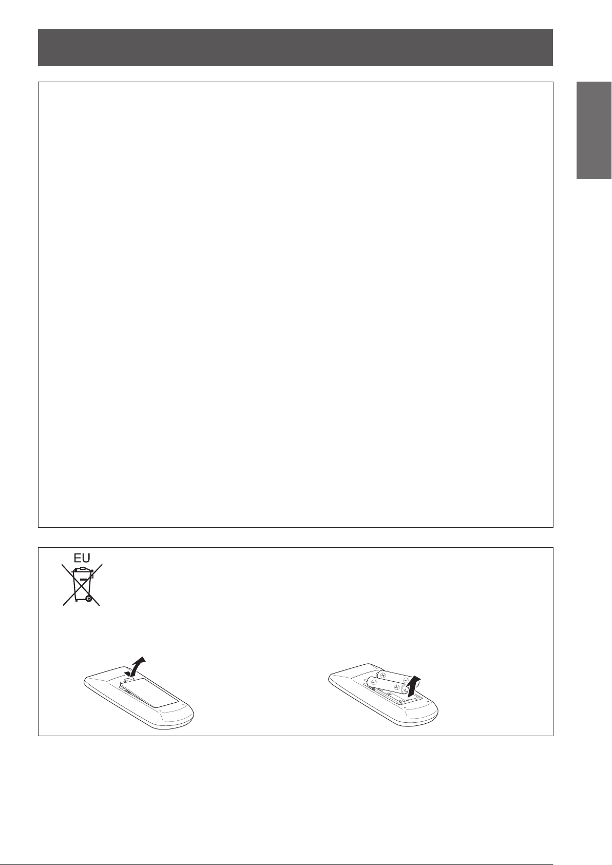
To remove the battery
Remote Control Battery
1. Press the guide and lift the cover. 2. Remove the batteries.

Read this rst!
Information
Important
Trademarks
•
•
•
•
•
•
Please note that the operating instructions do not include the ® and ™ symbols.
Illustrations in these operating instructions
•
Page references
•
Term
•
Microsoft
registered trademarks or trademarks of Microsoft Corporation in the United States and/or other countries.
Macintosh, Mac OS and Safari are the trademarks of Apple Inc. registered in the United States and other countries.
HDMI, the HDMI logo and High-Denition Multimedia Interface is a trademark or registered trademark of HDMI
Licensing LLC.
PJLink
RoomView, Crestron RoomView are registered trademarks of Crestron Electronics, Inc, and Crestron
Connected and Fusion RV are the trademarks of Crestron Electronics, Inc.
Other names, company names or product names used in these operating instructions are the trademarks or
registered trademarks of their respective holders.
Note that illustrations of the projector and screens may differ from the ones you actually see.
In these instructions, references to pages are indicated as: (
In these instructions, the “Wireless remote control unit” accessory is referred to as the “Remote control”.
®
and its logos, Windows®, Windows® XP, Windows Vista®, Windows 7®, and Internet Explorer ®are the
™
is a trademark or pending trademark in Japan, the United States, and other countries and regions.
page 00).
Æ
8
- ENGLISH

Auto Setup Function
Features of the ProjectorFeatures of the Projector
Quick stepsQuick steps
For details, see the corresponding pages.
This function executes Input search,
Auto PC adjustment and Auto
Keystone correction at the same time
by pressing the <AUTO SETUP>
button on the remote control.
Direct Power Off Function
With the Direct Power Off function,
you can disconnect the power cord
from the wall outlet or turn off the
breaker even during projection.
Improved connectivity
This function supports technology
that can transmit a video and
audio signal except Ethernet signal
through a twisted pair cable, and
without complex cable connections.
1. Set up your projector.
(Æpage 22)
2. Connect with other devices.
(Æpage 26)
3. Connect the power cord.
(Æpage 27)
4. Power on.
(Æpage 29)
Useful Functions for Presentations
The digital zoom function allows
you to focus on the crucial
information during a presentation.
The MIC function and 10 W audio
output allows you to make a
presentation without any external
audio equipment.
5. Select the input signal.
(Æpage 32)
6. Adjust the image.
(Æpage 32)
ENGLISH -
9

10
- ENGLISH
Important
Information
Preparation Getting Started Basic Operation Settings Maintenance Appendix
Contents
Be sure to read “Read this rst!”. ( pages 2 to 8)
Important Information
Read this rst! ........................................... 2
Contents ................................................... 10
Precautions for Use................................. 12
Preparation
About Your Projector .............................. 17
Using Remote control ............................. 21
Getting Started
Setting up ................................................. 22
Connections ............................................. 26
Basic Operation
Powering ON/OFF .................................... 27
Projecting ................................................. 32
Basic operations by using the remote
Cautions when transporting .......................................... 12
Cautions when installing ............................................... 12
Security ........................................................................ 13
Disposal ........................................................................ 14
Cautions on use ........................................................... 14
Accessories .................................................................. 15
Optional accessories .................................................... 16
Remote control ............................................................. 17
Projector body .............................................................. 18
Control panel and Indicators ........................................ 19
Rear terminals .............................................................. 20
Installing and Removing batteries ................................ 21
Setting Remote control ID numbers ............................. 21
Projection method ........................................................ 22
Parts for ceiling mount (Optional) ................................. 22
Screen size and throw distance ................................... 23
Adjusting front adjustable feet ...................................... 25
Adjusting the position by using the vertical lens shift
function ................................................................. 25
Before connecting to the projector ............................... 26
Connecting example ..................................................... 26
Connecting the power cord .......................................... 27
ON(G)/STANDBY(R) indicator...................................... 28
Turning On the Projector .............................................. 29
Enter a PIN code .......................................................... 30
Turning Off the Projector .............................................. 31
Selecting the input signal ............................................. 32
How to adjust the state of the image ............................ 32
control................................................... 33
Using the AUTO SETUP function ................................. 33
Switching the input signal ............................................. 33
Using the SCREEN button ........................................... 33
Using the KEYSTONE button ....................................... 34
Using the INFO. button ................................................. 34
Using the FREEZE function ......................................... 34
Using the AV MUTE function ........................................ 35
Using the P-TIMER button ........................................... 35
Using the LAMP button ................................................ 35
Using the D.ZOOM buttons .......................................... 35
Controlling the volume of the speaker .......................... 35
Using the IMAGE button ............................................... 36
Using the MUTE button ................................................ 36
Settings
Menu Navigation ...................................... 37
Navigating through the menu ....................................... 37
Main menu .................................................................... 38
Sub menu ..................................................................... 38
Input menu ............................................... 40
Computer 1: RGB/Component /RGB (Scart) ............... 40
Computer 2: RGB ......................................................... 40
HDMI ............................................................................ 40
Video ............................................................................ 40
S-video ......................................................................... 40
DIGITAL LINK ............................................................... 40
System ......................................................................... 40
AUTO PC adjust ....................................... 42
Auto PC adj. ................................................................. 42
Manual PC adjust ..................................... 43
Fine sync ...................................................................... 43
Total dots ...................................................................... 43
Horizontal ..................................................................... 43
Vertical .......................................................................... 43
Current mode ............................................................... 44
Clamp ........................................................................... 44
Display area H .............................................................. 44
Display area V .............................................................. 44
Reset ............................................................................ 44
Mode free ..................................................................... 44
Store ............................................................................. 44
Image select ............................................ 45
Dynamic ....................................................................... 45
Standard ....................................................................... 45
Real .............................................................................. 45
Cinema ......................................................................... 45
Blackboard(Green) ....................................................... 45
Colorboard .................................................................... 45
Image 1-4 ..................................................................... 45
Image adjust............................................. 46
Contrast ........................................................................ 46
Brightness .................................................................... 46
Color ............................................................................. 46

ENGLISH -
11
Important
Information
PreparationGetting StartedBasic OperationSettingsMaintenanceAppendix
Contents
Tint .............................................................................. 46
Iris .............................................................................. 46
Color temp. ................................................................... 47
Red .............................................................................. 47
Green ........................................................................... 47
Blue ............................................................................. 47
Daylight View ............................................................... 47
Sharpness .................................................................... 48
Gamma ......................................................................... 48
Noise reduction ............................................................ 48
Progressive .................................................................. 48
Reset ............................................................................ 48
Store ............................................................................. 48
Screen ...................................................... 49
Normal .......................................................................... 49
Full .............................................................................. 49
Wide(16:9) .................................................................... 49
Zoom ............................................................................ 49
True .............................................................................. 49
Natural wide ................................................................. 49
Custom ......................................................................... 49
Custom adj. .................................................................. 50
Digital zoom +............................................................... 50
Digital zoom – .............................................................. 50
Keystone ...................................................................... 50
Ceiling .......................................................................... 51
Rear .............................................................................. 51
Screen aspect .............................................................. 51
Reset ............................................................................ 51
Sound ....................................................... 52
Volume ......................................................................... 52
Mute ............................................................................. 52
MIC .............................................................................. 52
MIC gain ....................................................................... 52
In standby mode ........................................................... 52
Setting ...................................................... 53
Language ..................................................................... 53
Menu position ............................................................... 53
Auto setup .................................................................... 53
Background .................................................................. 54
Display .......................................................................... 54
Logo ............................................................................. 54
HDMI setup .................................................................. 55
DIGITAL LINK signal level ............................................ 55
Terminal ........................................................................ 55
Power management ..................................................... 55
Direct on ....................................................................... 56
Standby mode .............................................................. 56
P-timer .......................................................................... 56
Closed caption .............................................................. 57
Lamp power .................................................................. 57
Remote control ............................................................. 57
Security ........................................................................ 57
Fan .............................................................................. 58
Fan control ................................................................... 58
Video delay control ....................................................... 59
Filter counter ................................................................ 59
Emulate ........................................................................ 59
RS232C ........................................................................ 60
Warning log .................................................................. 60
Factory default .............................................................. 60
Information ............................................... 61
Input Source Information Display ................................ 61
Network .................................................... 62
DIGITAL LINK mode ..................................................... 62
DIGITAL LINK setup ..................................................... 62
DIGITAL LINK status .................................................... 62
Projector name ............................................................. 63
Network setup .............................................................. 63
Network control ............................................................ 64
Network status .............................................................. 64
AMX D.D. ..................................................................... 64
RoomView .................................................................... 64
Extron XTP ................................................................... 64
Digital Interface Box ..................................................... 64
Network factory default ................................................. 64
Network connections .................................................... 65
Twisted pair cable Extender connections ..................... 66
Computer operation ...................................................... 67
Accessing from the Web browser ................................. 67
Maintenance
LAMP and WARNING Indicators ............ 79
Managing the indicated problems ................................ 79
Replacement ............................................ 80
Before replacing the unit .............................................. 80
Maintenance ................................................................. 80
Replacing the unit ......................................................... 80
Attaching the Lens Cap ................................................ 84
Troubleshooting ...................................... 85
Appendix
Technical Information ............................. 87
PJLink protocol ............................................................. 87
Control commands via LAN .......................................... 88
Serial terminal .............................................................. 90
Other terminals ............................................................. 93
List of compatible signals ............................................. 94
Specications .......................................... 98
Dimensions ................................................................. 100
Ceiling mount bracket safeguards....... 100
Index ....................................................... 101

12
- ENGLISH
Important
Information
Precautions for Use
Cautions when transporting
z
z
Cautions when installing
J
z
J
z
z
z
J
This requires an optional ceiling mount bracket.
Model No.: ET-PKV100H (for high ceilings), ET-PKV100S (for low ceilings),
When transporting the projector, hold it securely by its bottom and avoid excessive vibration and impacts.
Doing so may damage the internal parts and result in malfunctions.
Do not transport the projector with the adjustable feet extended. Doing so may damage the adjustable feet.
Do not set up the projector outdoors.
The projector is designed for indoor use only.
Do not use under the following conditions.
Places where vibration and impacts occur such as in a car or vehicle: Doing so may damage the internal parts
and result in malfunctions.
Near the exhaust of an air conditioner or near lights (studio lamps, etc.) where temperature changes greatly
(Operating environment Æpage 99): Doing so may shorten the life of the lamp or result in deformation of the
outer case and malfunctions.
Near high-voltage power lines or near motors: Doing so may interfere with the operation of the projector.
Be sure to ask a specialized technician when installing the product to a
ceiling.
ET-PKV200B (Projector Mount Base).
J
Qualied cable is required for DIGITAL LINK connection, be sure to consult
a specialized technician or your dealer.
Imperfect wiring may cause poor performance of cable transmission, such as distorted or choppy image and
sound.
J
The interface box may not work properly due to strong radiowave from the
broadcast station or the radio.
If there is any facility or equipment, which outputs strong radiowave, near the installation location, install the
interface box at a location sufciently far from the source of the radiowave. Or, wrap the LAN cable connected to
the <DIGITAL LINK> terminal by using a piece of metal foil or a metal pipe, of which is grounded at both ends.
J
When using the projector in the elevation of below 1 200 m (3 937 ft), make
sure [Fan control] is set to [Off].
Failure to do so may shorten the life of the internal parts and result in malfunctions.
J
When using the projector in the elevation of above 1 200 m (3 937 ft) and
below 2 000 m (6 562 ft), make sure [Fan control] is set to [On 1].
Failure to do so may shorten the life of the internal parts and result in malfunctions.
J
When using the projector in the elevation of above 2 000 m (6 562 ft) and
below 2 700 m (8 858 ft), make sure [Fan control] is set to [On 2].
Failure to do so may shorten the life of the internal parts and result in malfunctions.
J
Do not install the projector at elevations of 2 700 m (8 858 ft) or higher
above sea level.
Failure to do so may shorten the life of the internal parts and result in malfunctions.

Precautions for Use
ENGLISH -
13
Important
Information
MONITOR OUT
COMPUTER 2 IN
COMPUTER 1 IN
SERIAL IN
VIDEO IN
AUDIO IN
LAN
MIC IN
S-VIDEO IN
COMPUTER
AUDIO IN
VARIABLE
AUDIO OUT
R
L
AC IN ~
MONITOR OUT
COMPUTER 2 IN
COMPUTER 1 IN
SERIAL IN
VIDEO IN
AUDIO IN
LAN
MIC IN
S-VIDEO IN
COMPUTER
AUDIO IN
VARIABLE
AUDIO OUT
R
L
AC IN ~
J
Do not tilt the projector or place it on its side.
Do not tilt the projector body more than approximately ±30 degrees vertically or ±15 degrees horizontally. Over
tilting may result in shortening the life of the components.
Within +30°
Within +15°
Within -30°
J
Cautions when setting the projectors
Within -15°
zDo not stack the projectors.
Do not block the ventilation ports (intake and exhaust) of the
z
projector.
Avoid heating and cooling air from the air conditioning system
z
directly blow to the ventilation ports (intake and exhaust) of the
projector.
over 50 cm
(20")
over 20 cm
(7.8")
over 50 cm
(20")
over 1 m (40")
Do not place the projector in an enclosed space.
z
If you need to place the projector in an enclosed space, additional air conditioning and ventilation system
must be equipped. When ventilation is insufcient, remaining heat may trigger the protection circuit of the
projector.
Security
J
Take safety measures against following incidents.
Personal information being leaked via this product.
z
Unauthorized operation of this product by a malicious third party.
z
Interfering or stopping of this product by a malicious third party.
z
J
Security instruction (
Make your password as difcult to guess as possible.
z
Change your password periodically.
z
Panasonic or its afliate company never inquires a password directly to a customer. Do not tell your password
z
in case you receive such an inquiry.
The connecting network must be secured by rewall or others.
z
Set a password for web control and restrict the users who can log in.
z
page 57, 76)
Æ

Precautions for Use
14
- ENGLISH
Important
Information
Disposal
When disposing of the product, ask your local authority or dealer about the correct methods of disposal.
The lamp contains mercury. When disposing of the used lamp unit, ask your nearest local authorities or dealer
about proper disposal of the unit.
Dispose of used batteries according to the instructions or your local disposal rule or guidelines.
Cautions on use
J
z
z
z
J
If the surface of the lens becomes dirty from ngerprints or anything else, this will be magnied and projected
onto the screen.
J
The display unit of this projector comprises three LCD panels. Although an LCD panel is a product of highprecision technology, some of the pixels on the projected image may be missing or constantly lit. Please note that
this is not a malfunction.
Displaying a still image for a longer time may result in an after-image on the LCD panels. If this happens, display
the all white screen in the test pattern for an hour or more.
In order to get the picture quality
Draw curtains or blinds over windows and turn off any lights near the screen to prevent outside light or light
from indoor lamps from shining onto the screen.
Depending on where the projector is used, heated air from an exhaust port or warm or cold air from an air
conditioner can cause a shimmering effect on screen.
Avoid use in locations where exhaust or streams of air from projector, other devices and air conditioners ow
between the projector and the screen.
The lens of projector is affected by the heat from the luminous source. Because of this, the focusing may not
be stable right after the power is turned on. Focusing is stabled after projecting image for 30 minutes and
longer.
Do not touch the surface of the projector lens with your bare hand
LCD Panel
J
Optical components
Operating the projector in an environment with high temperature or heavy exposure to dust or tobacco smoke
will reduce the service life of the optical components, such as the LCD panel and polarizing plate, and may
necessitate their replacement within less than one year of use. For details, consult your dealer.
J
Lamp
The luminous source of the projector is a mercury lamp with high internal pressure.
A high pressure mercury lamp has following characteristics.
The brightness of the lamp will decrease by duration of usage.
z
The lamp may burst with sound or shorten life by shock or chipping.
z
The life of the lamp varies greatly depending on individual specicities and usage conditions. In particular,
z
continuous use over 12 hours and frequent on/off switching of the power greatly deteriorate the lamp and
affect the lamp life.
In rare cases, the lamp burst shortly after the projection.
z
The risk of bursting increases when the lamp is used beyond its replacement cycle. Make sure to replace the
z
lamp unit consistently. (“When to replace the lamp unit” (Æpage 82))
If the lamp bursts, gas contained inside of the lamp is released in a form of smoke.
z
It is recommended to store replacement lamps for contingency.
z
It is recommended to have authorized engineer or your dealer replace the lamp unit.
z
J
Avoidance of damage to connection terminal resulting from static electricity
Please pay attention to the following points when connecting the signal cable. Failure to do so may cause a
failure in the product.
When connecting the cable to the projector or to the external devices connected to the projector, touch a
z
metallic object in your vicinity to discharge any static electricity from your body before handling the cable.
Pursuant to at the directive 2004/108/EC, article 9(2)
Panasonic Testing Centre
Panasonic Service Europe, a division of Panasonic Marketing Europe GmbH
Winsbergring 15, 22525 Hamburg, F.R. Germany

Precautions for Use
ENGLISH -
15
Important
Information
Accessories
Make sure the following accessories are provided with your projector. Numbers in the brackets ( ) show the
number of accessories.
Remote control unit (x1)
(6451058157)
RGB signal cable (x1)
(6103580425)
Power cord (x2)
(6103580203)
(6103580210)
AC power cord holder (x1)
(6451052124)
CD-ROM (x1)
(6103627656)
Lens cap (x1)
(6103594279)
Batteries (AAA/R03 or
AAA/LR03 type) (x2)
(for remote control unit)
String (x1)
(6103504711)
Soft Carrying Case (x1)
(6103601861)
Attention
After unpacking the projector, discard the power cord cap and packaging material properly.
z
For lost accessories, consult your dealer.
z
The part numbers of accessories and separately sold components are subject to change without notice.
z
Store small parts in an appropriate manner, and keep them away from young children.
z
(Attached to the projector
at the time of purchase.)
Precautions for Use
Information
Important
J
The contents of the supplied CD-ROM are as follow.
Contents of the supplied
Manual/list (PDF) Software
CD-ROM
Operating Instructions – Functional
Manual
Operation Manual Multi Projector
Monitoring & Control Software 2.7
Operation Manual Logo Transfer
Software 2.0
List of compatible projector models
•
This is a list of projectors that are compatible with
the software (refer to the right column), and their
restrictions.
Multi Projector Monitoring & Control
Software 2.7 (Windows)
•
This software allows you to monitor and control
multiple projectors connected to the LAN.
Logo Transfer Software 2.0 (Windows)
•
This software allows you to create original
images, such as company logos to be displayed
when projection starts, and transfer them to the
projector.
Optional accessories
Options Model No.
Ceiling Mount Bracket
Projector Mount Base ET-PKV200B
Replacement Lamp Unit ET-LAV200
Replacement Filter Unit
Digital Interface Box ET-YFB100G
ET-PKV100H (for high ceilings),
ET-PKV100S (for low ceilings)
ET-RFV200
16
- ENGLISH
About Your Projector
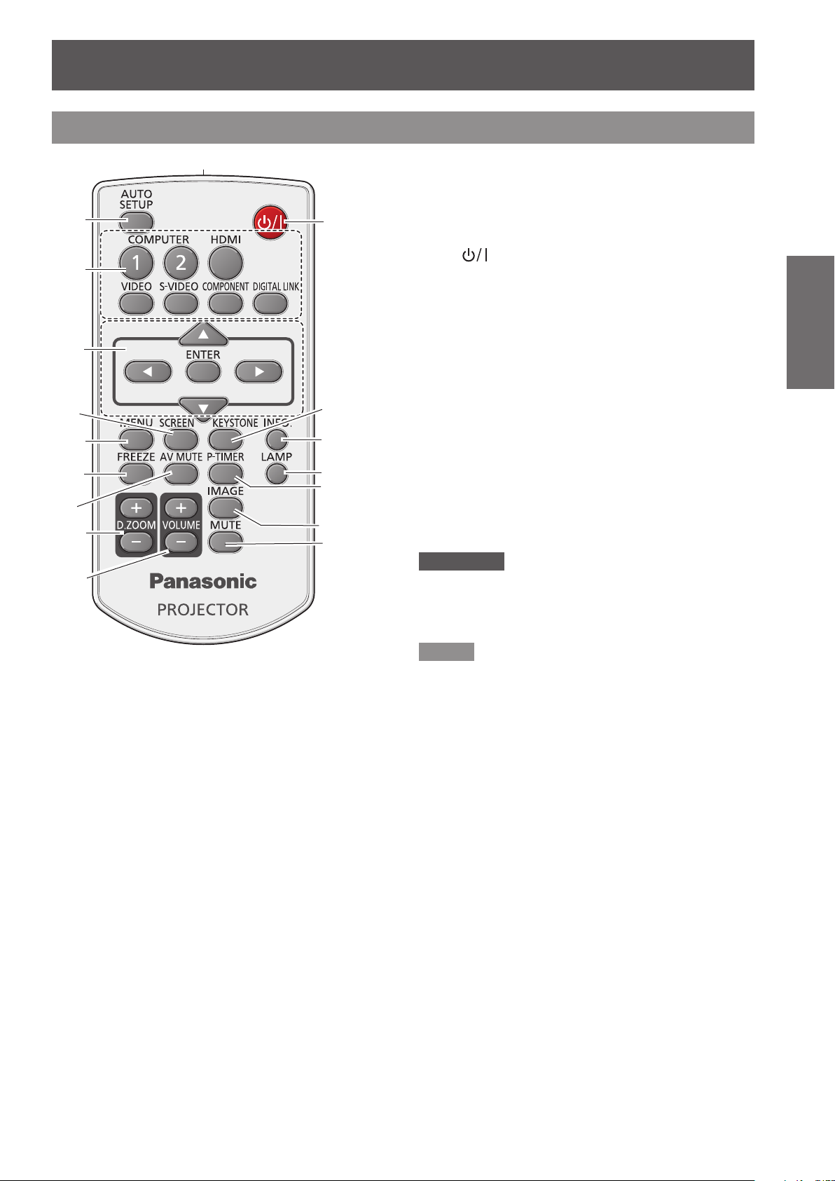
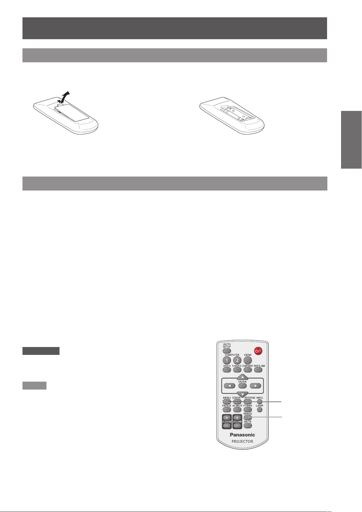
Remote control
(1)
(2)
(3)
(4)
(5)
(6)
(7)
(8)
(9)
(17)
(10)
(11)
(12)
(13)
(14)
(15)
(16)
(8) <D.ZOOM +/–> Buttons
Zoom in and out the images. (Æpage 35)
(9) <VOLUME +/–> Buttons
Adjust the volume of the speaker. (Æpage 35)
(10) < > Button
Turn the projector on or off. (Æpage 29)
(11) <KEYSTONE> Button
Correct keystone distortion. (Æpage 34)
(12) <INFO.> Button
Operate the information function. (Æpage 34)
(13) <LAMP> Button
Select a lamp mode. (Æpage 35)
(14) <P-TIMER> Button
Operate the P-timer function. (Æpage 35)
(15) <IMAGE> Button
Select the image mode. (Æpage 36)
(16) <MUTE> Button
Mute the sound. (Æpage 36)
(17) Remote control signal emitter
Attention
Do not drop the remote control.
z
Avoid contact with liquids.
z
Do not attempt to modify or disassemble the remote
z
control.
Preparation
(1) <AUTO SETUP> Button
Execute the setting of Auto setup in the setting
menu. (Æpage 53)
(2) Input Selection Buttons: <COMPUTER 1>,
<COMPUTER 2>, <HDMI>, <VIDEO>,
<S-VIDEO>, <COMPONENT>,
<DIGITAL LINK>.
These buttons are used to select the input
signal. (Æpage 33)
(3) ▲▼◄► Buttons, <ENTER> Button
Navigate the MENU display. (Æpage 37)
(4) <SCREEN> Button
Select a screen mode. (Æpage 33)
(5) <MENU> Button
Open or close the On-Screen Menu.
(Æpage 37)
(6) <FREEZE> Button
Pause the projected image and sound
tentatively. (Æpage 34)
(7) <AV MUTE> Button
Temporarily turn off the image on the screen.
(Æpage 35)
Note
The remote control can be used within a distance of
z
about 7 m (22.97 ft) if pointed directly at the remote
control signal receiver. The remote control can control at
angles of up to ± 30 ° vertically and ± 30 ° horizontally,
but the effective control range may be reduced.
If there are any obstacles between the remote control
z
and the remote control signal receiver, the remote control
may not operate correctly.
You can operate the projector by reecting the remote
z
control signal on the screen. The operating range may
differ due to the loss of light caused by the properties of
the screen.
When the remote control signal receiver is lit with a
z
uorescent light or other strong light source, the projector
may become inoperative. Set the projector as far from
the luminous source as possible.
ENGLISH -
17

About Your Projector
18
- ENGLISH
Preparation
■
Bottom view
Projector body
(1) (2)
(1) Remote control signal receiver
(2) Focus Lever (Æpage 32)
(3) Projection Lens
(4) Zoom Lever (Æpage 32)
(5) Vertical lens shift ring (Æpage 25)
(6) Control Panel and Indicators (Æpage 19)
(7) Lamp cover (Æpage 83)
(8) Air outlet port
•
(9) Speaker
(10) AC IN
(11) Rear terminals (Æpage 20)
(12) Air intake port / Air lter cover (Æpage 80)
(13) Adjustable feet
(5)
(3)
(4)
Adjust the focus.
Adjust the zoom.
Adjust the vertical position of the projected
image.
The lamp unit is located inside.
Hot air is exhausted from the exhaust vent. Do
not put heat-sensitive objects near this side.
Adjust the projection angle.
(6)
(7)
(9)
(10)
(8)
(13)
(11)
WARNING:
Keep your hands and other objects away from
the air exhaust port.
z
Keep your hand and face away.
z
Do not insert your nger.
z
Keep heat-sensitive articles away.
Heated air from the air exhaust port can cause burns
or external damage.
(12)

About Your Projector
ENGLISH -
19
Preparation
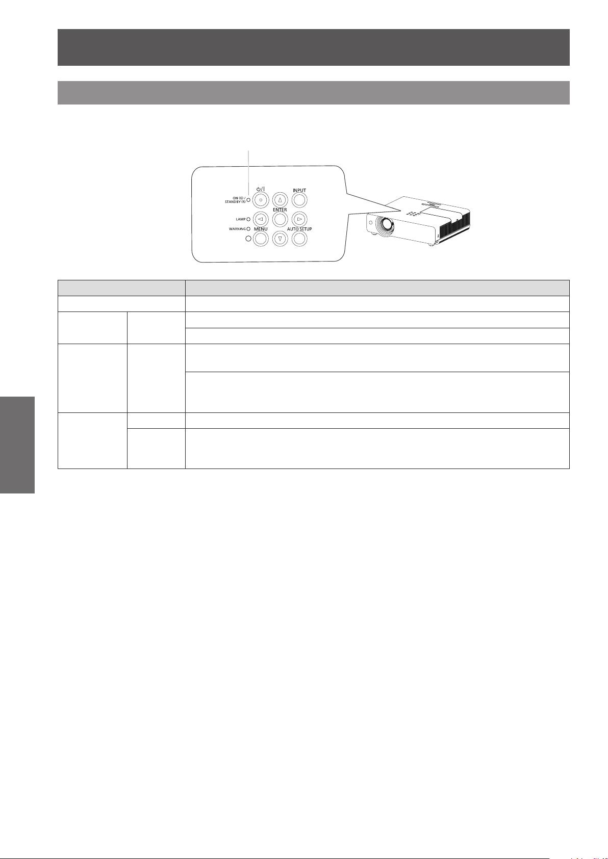
Control panel and Indicators
(1)
(2)
(3)
(4)
(5)
(6)
(1) < > button
Turns the projector on/off.
(2) <ON(G)/STANDBY(R)> indicator
Indicates the power status.
(3) <LAMP> indicator
Lights yellow when the projection lamp reaches
its end of life.
(4) <WARNING> indicator
Indicates the abnormal conditions of the
projector.
(5) Ambient Luminance sensor
Detects room's light and select proper image
quality.
(9)
(10)
(7) (8)
(6) <MENU> button
Turns the main menu on/off. (Æpage 37)
(7) <ENTER> button
Executes the selected item.
(8) ▲▼◄► buttons
Navigates the MENU screen.
Adjust the volume level or mute the sound.
(9) <INPUT> button
Selects the input signal. (Æpage 33)
(10) <AUTO SETUP> button
Executes auto setup.
About Your Projector
20
- ENGLISH
Preparation
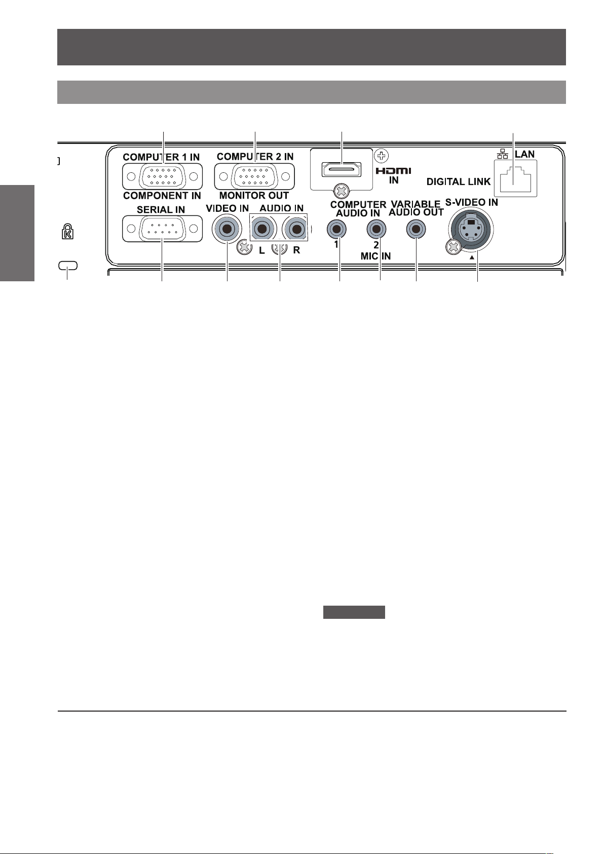
Rear terminals
(5)
(1) COMPUTER 1 IN / COMPONENT IN
(2) COMPUTER 2 IN / MONITOR OUT
(3) HDMI IN
(4) LAN / DIGITAL LINK
(5) Security slot
(6) SERIAL IN
(1)
(6)
Connects to COMPUTER 1 IN/ COMPONENT
IN input signals.
Connects to COMPUTER 2 IN/ MONITOR OUT
input signals or outputs the analog RGB signals
input the projector.
Connects to HDMI input signals.
Connects to a LAN cable for network
connection; or connects to a LAN cable for
video and audio connection without complex
cable connections.
Attaches the commercial shackle lock,
manufactured by Kensington, to protect your
projector. Compatible with the Kensington
MicroSaver Security System.
Connects to a computer via an RS-232C cable.
(7)
(8)
(3)(2)
(10)(9)
(7) VIDEO IN
Connects to VIDEO input signals.
(8) AUDIO IN
Connects the audio output signals from video
equipment connected to (7) or (12) to this jack.
(9) COMPUTER AUDIO IN 1
Connects the audio output signals from a
computer connected to (1) to this jack.
(10) COMPUTER AUDIO IN 2 (MIC IN)
Connects the audio output signals from a
computer connected to (2) to this jack.
(11) VARIABLE AUDIO OUT
Outputs the audio signals input to the projector.
(12) S-VIDEO IN
Connects to S-VIDEO input signals.
Attention
When a LAN cable is directly connected to the projector,
z
the network connection must be made indoors.
(11)
(12)
(4)
DIGITAL LINK is a technology to send image and sound signals via twisted pair cable.
The optional accessory Digital Interface Box (ET-YFB100G) and Extron's XTP transmitter are only matched
for this projector. For twisted-pair-cable transmitter of other manufacturers of which the operation has been
veried with the DIGITAL LINK compatible projector, refer to Panasonic website (http://panasonic.net/avc/
projector/). Note that the verication for devices of other manufacturers has been made for the items set by
Panasonic Corporation, and not all the operations have been veried. For operation or performance problems
caused by the devices of other manufacturers, contact the respective manufacturers.
Using Remote control
ENGLISH -
21
Preparation
Using Remote control
Installing and Removing batteries
Open the cover1 ) Install batteries and close the cover2 )
(Insert the – side rst.)
z
Remove the batteries in the reverse order of
installation.
Setting Remote control ID numbers
When you use the system with multiple projectors, you can operate all the projectors simultaneously or each
projector individually using single remote control, if unique ID number is assigned to each projector.
After setting the ID number of the projector, set the same ID number to the remote control.
There are 7 different ID codes (ALL, Code 1~Code 6), the initial ID number is [ALL].
J
Setting the ID number
1) While holding down the <MENU> button, press the <IMAGE> button. The number of times you press
the <IMAGE> button corresponds to the desired ID code number.
The number of times to press the <IMAGE> button is as follows:
Code 1= Once, Code 2= Twice, Code 3= 3 times, Code 4= 4 times
Code 5= 5 times, Code 6= 6 times.
2) The ID code is changed when the <MENU> button is released.
J
Resetting the ID number
The ID code is reset to [ALL] (default) by pressing the <MENU> button and <IMAGE> button at the
same time for 5 seconds or more.
Attention
z
If the <IMAGE> button is pressed 7 times or more, the ID code
cannot be changed (the operation is invalid).
Note
For details, please refer to the [Remote control] of the [Setting] menu.
z
(Æpage 57)
MENU button
IMAGE button

22
- ENGLISH
Getting Started
Setting up
Projection method
You can use the projector with any of the following 4 projection methods. To set the desired method in the projector.
J
Setting on a desk/oor and
projecting forward
Menu setting*
Ceiling Off
Rear Off
J
Mounting on the ceiling and
projecting from rear
(Using translucent screen)
J
Mounting on the ceiling and
projecting forward
1
Menu setting*
Ceiling On
Rear Off
J
Setting on a desk/oor and
1
projecting from rear
(Using translucent screen)
Menu setting*
Ceiling On
Rear On
For details about the menu setting, please refer to the [Screen] menu → [Ceiling] and [Rear]. (*1 :
1
Menu setting*
Ceiling Off
Rear On
1
page 51)
Æ
Parts for ceiling mount (Optional)
You can install the projector on the ceiling by using the optional ceiling mount bracket (ET-PKV100H: for high
ceiling, ET-PKV100S: for low ceiling), and the optional projector mount base ET-PKV200B.
z
Use only the ceiling mount brackets specied for this projector.
z
Refer to the installation manual for the ceiling mount bracket when you install the bracket and the projector.
Attention
z
To ensure projector performance and security, installation of the ceiling mount bracket must be carried by your
dealer or a specialized technician.

Setting up
ENGLISH -
23
Getting Started
Screen size and throw distance
Place the projector referring
Projected image
to the diagram on the right
and the gures of throwing
distance. You can adjust the
display size.
SH
SD
SW
SH
Screen
L (LW/LT)
H
L (LW/LT) *1Projection distance (m)
SH Height of the projection area (m)
SW Width of the projection area (m)
H
Distance from the center of lens to the
image lower end (m)
SW
L (LW/LT)
Screen
SD Diagonal length of the projection area (m)
LW : Minimum distance *1 :
LT : Maximum distance
Attention
Before installing, please read “Precautions for Use” (
z
J
Projection distance
pages 12 to 16).
Æ
All measurements below are approximate and may differ slightly from the actual measurements. (Unit: m)
Projection
size
Screen
diagonal
(SD)
0.76 (30") 0.8 1.4 0.009~0.229 0.8 1.3 0.007~0.187 0.7 1.2 0.008~0.202
1.02 (40") 1.1 1.8 0.012~0.305 1.0 1.7 0.010~0.249 1.0 1.6 0.011~0.269
1.27 (50") 1.4 2.3 0.015~0.381 1.3 2.1 0.012~0.311 1.3 2.0 0.013~0.337
1.52 (60") 1.7 2.8 0.018~0.457 1.6 2.5 0.015~0.374 1.5 2.5 0.016~0.404
1.78 (70") 2.0 3.3 0.021~0.533 1.8 3.0 0.017~0.436 1.8 2.9 0.019~0.471
2.03 (80") 2.3 3.7 0.024~0.610 2.1 3.4 0.020~0.498 2.0 3.3 0.022~0.538
2.29 (90") 2.6 4.2 0.027~0.686 2.3 3.8 0.022~0.560 2.3 3.7 0.024~0.606
2.54 (100") 2.9 4.7 0.030~0.762 2.6 4.2 0.025~0.623 2.5 4.1 0.027~0.673
3.05 (120") 3.5 5.6 0.037~0.914 3.1 5.1 0.030~0.747 3.1 4.9 0.032~0.808
3.81 (150") 4.3 7.0 0.046~1.143 3.9 6.4 0.037~0.934 3.8 6.2 0.040~1.010
5.08 (200") 5.8 9.4 0.061~1.524 5.3 8.5 0.050~1.245 5.1 8.3 0.054~1.346
6.35 (250") 7.3 11.7 0.076~1.905 6.6 10.6 0.062~1.557 6.4 10.3 0.067~1.683
7.62 (300") 8.7 14.0 0.091~2.286 7.9 12.7 0.075~1.868 7.7 12.4 0.081~2.019
Minimum
For 4:3 aspect ratio For 16:9 aspect ratio For 16:10 aspect ratio
distance
(LW)
Maximum
distance
(LT)
Height
position (H)
Minimum
distance
(LW)
Maximum
distance
(LT)
Height
position (H)
Minimum
distance
(LW)
Maximum
distance
(LT)
Height
position (H)

Setting up
24
- ENGLISH
Getting Started
Any other projection distance can be obtained according to the screen dimensions (m) using the following
calculations.
The calculated distance may contain a certain error.
If the screen dimensions are written as “SD",
Screen height (SH) = SD(m) × 0.6 = SD(m) × 0.490 = SD(m) × 0.530
Screen width (SW) = SD(m) × 0.8 = SD(m) × 0.872 = SD(m) × 0.848
Minimum distance (LW) = 0.11461 × SD(m) - 0.02936 = 0.10402 × SD(m) - 0.02936 = 0.10122 × SD(m) - 0.02936
Maximum distance (LT) = 0.18465 × SD(m) - 0.03190 = 0.16764 × SD(m) - 0.03190 = 0.16311 × SD(m) - 0.03190
For 4:3 aspect ratio For 16:9 aspect ratio For 16:10 aspect ratio

Setting up
ENGLISH -
25
Getting Started
48%
Adjusting front adjustable feet
Lift the front of the projector and press the feet lock latches on both side of the projector.
Release the feet lock latches to lock the adjustable feet and rotate the adjustable feet to a proper height and tilt.
You can turn the front adjustable feet to extend them. You can turn them in the opposite direction to contract
them.
(You can adjust the projection angle vertically.)
Feet Lock Latches
Adjustable range
Front adjustable feet : 48.5 mm(1.909")
Attention
Heated air comes out of the air exhaust port while the lamp is lit. Do not touch the air exhaust port directly when you adjust
z
the front adjustable feet.
If keystone distortion occurs on the projected image, perform “KEYSTONE” from the “Screen” menu. (
z
page 50)
Æ
Note
Screw up the adjustable feet, and an audible click will be heard as the limit.
z
Adjusting the position by using the vertical lens shift function
If the projector is not positioned right in front of the center of the screen, you can adjust the vertical position of
projected image by moving the vertical lens ring within the shift range of the lens.
Lens shift adjustment
The display position can be shifted
upward up to 48% elevation of the
display. (When turn the vertical lens shift
ring to the right (left), the display moves
up (down)).
Lens shift adjustable range
Lens shift center
position
Shift range
Attention
Please note the followings when using the projector.
Do not touch the lens while it is moving as this could cause injury to the ngers.
z
Never allow children to touch the lens.
z
Connections
Before connecting to the projector
z
Read carefully the instruction manual for the device to be connected.
z
Turn off the power switch of the devices before connecting cables.
z
If any connection cable is not supplied with the device, or if no optional cable is available for connection of the
device, prepare a necessary system connection cable to suit the device.
z
Video signals containing too much jitter may cause the images on the screen to randomly wobble or wafture.
In this case, a time base corrector (TBC) must be connected.
z
The projector accepts the following signals: VIDEO, S-VIDEO, analogue-RGB (with TTL sync. Level) and
digital signal.
z
Some computer models are not compatible with the projector.
z
When using long cables to connect with each of equipment to the projector, there is a possibility that the image
will not be output correctly unless a compensator is used.
z
For details on what video signals the projector supports, see “List of compatible signals”. (
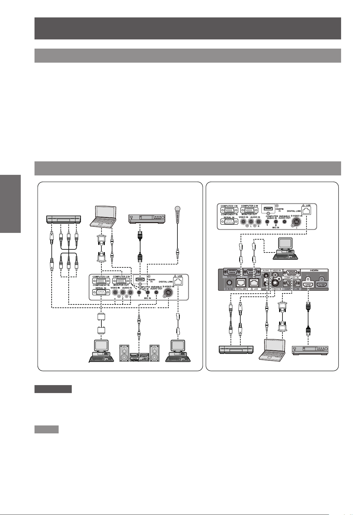
Connecting example
Getting Started
Video deck
(TBC built-in)
Normal external equipment connection example
Computer
Blue ray player
MIC
pages 94-97)
Æ
Connection example for twisted pair cable
transmitter
Projector rear terminals
Control computer
Attention
When connecting with a video deck, be sure to use the one with a built-in time base corrector (TBC) or use a TBC between
z
the projector and the video deck.
If nonstandard burst signals are connected, the image may be distorted. If this is the case, connect a TBC between the
z
projector and the video deck.
Projector rear
terminals
Audio equipment
Control computer
Video deck
(TBC built-in)
Control computer
When connecting with ET-YFB100G
(Optional accessory)
Computer
Blue ray player
Note
When using an HDMI cable, check that it is compliant with the HDMI standard. Using a cable that is not compliant with the
z
HDMI standard may result in problems such as the image cutting out or not appearing.
When connecting the 1080p signal using HDMI, use a cable compliant with 1080p signal.
This projector does not support the Viera link (HDMI).
z
The twisted pair cable Extender, such as Digital Interface Box (Optional accessory: ET-YFB100G) is used for sending video
z
and audio signals via a twisted pair cable, and the <DIGITAL LINK> jack of the projector can be used for receiving these
digital signals. For details on connection, please see "Twisted pair cable Extender connections". (Æpage 66)
26
- ENGLISH

Basic Operation
Powering ON/OFF
Connecting the power cord
Be sure to insert the attached power cord securely to its base to prevent it from coming off.
J
Power cord holder
A power cord holder is designed to prevent the AC power cord from coming off the projector.
Please insert the power cord into the power cord holder correctly as Picture (1) shown:
AC Power cord holder
Clamp
Picture (1)
J
Attaching
Attach the AC power cord with the power cord clamps to the projector as follows:
Press the clamps on its sides, and then insert the AC power cord with the power cord clamps securely to the
projector as Picture (2) shown. It is correctly attached until you hear the "CLICK" sound. See Picture (3) for
correct attachment.
Picture (2) Picture (3)
J
Removal
Remove the AC power cord from the electrical outlet while pressing the clamps on its sides.
Basic Operation
ENGLISH -
27
Powering ON/OFF
28
- ENGLISH
Basic Operation
ON(G)/STANDBY(R) indicator
ON(G)/STANDBY(R) indicator
The ON(G)/STANDBY(R) indicator informs you the status of the power. Conrm the status of the
<ON(G)/STANDBY(R)> indicator before operating the projector.
Indicator status Status
No illumination or ashing The power cord is unplugged.
RED Lit
ORANGE Flashing
GREEN
The power cord is plugged.
The projector is in stand-by mode, after the cooling is completed.
The projector is cooling down. The projector cannot be turned on until cooling is
completed and the <ON(G)/STANDBY(R)> indicator stops blinking.
The temperature inside the projector is abnormally high. And the <WARNING>
indicator also blinks in red (Æpage 79). The projector cannot be turned on until
cooling is completed and the <ON(G)/STANDBY(R)> indicator stops blinking.
Lit Projecting.
The projector is in stand-by status with Power management function.
Flashing
The projection lamp will be turned on if the input signal is reconnected or any
button on the control panel or remote control is pressed. (Æ page 55)

Powering ON/OFF
ENGLISH -
29
Basic Operation
Turning On the Projector
(2)
Complete peripheral connections (with a 1 )
computer, VCR, etc.) before turning on the
projector.
Connect the projector’s AC power cord into an 2 )
AC outlet. The <ON(G)/STANDBY(R)> indicator
lights red. Open the lens cap.
Press the <3 ) > button to on the control
panel or on the remote control. The <ON(G)/
STANDBY(R)> indicator lights green and the
cooling fans start to operate. The preparation
display appears on the screen and the count
down starts.
After the countdown, the input source that was 4 )
selected the last time and the lamp power status
icon appear on the screen.
If there is no signal input when start on the 5 )
projector, or the current signal is missed while
operating the projector, the Video/Computer
selection window will be displayed on the screen,
please move the pointer to input source desired
by pressing the ▲▼ and the <ENTER> button.
And then follow the input signal guidance window
to correct the signal and connection.
(3)
(3)
Preparation display
06
The preparation display will disappear
after 30 seconds.
Selected input source and Lamp mode
Input source
Lamp power status
Video/Computer selection
If the projector is locked with a PIN code, PIN
code input dialog box will appear. Enter the PIN
code as instructed on the next page.
Note
When the Logo select function is set to [Off], the logo will
z
not be shown on the screen (Æpage 54).
When [Countdown off] or [Off] is selected in the Display
z
function, the preparation display will not be shown on the
screen (Æpage 54).
When the Input search function is set to [On 2], the input
z
signal will be searched automatically (Æpage 53).
When the Direct on function is set to [On], the projector
z
will be turned on automatically by connecting the AC
power cord to an AC outlet.

Powering ON/OFF
30
- ENGLISH
Basic Operation
Enter a PIN code
Press ▲▼ to enter a number. Press ► to x the
number and move the red frame pointer to the next
box. The number changes to . If you xed an
incorrect number, use the ◄ button to move the
pointer to the number you want to correct, and then
enter the correct number.
Repeat this step to complete entering a four-digit
number.
After entering the four-digit number, move the pointer
to “Set”. Press the <ENTER> button so that you can
start to operate the projector.
If you entered an incorrect PIN code, PIN code and
the number (
the correct PIN code all over again.
Note
If the PIN code number is not entered or wrong PIN code
z
number is entered within three minutes after the PIN
code dialog box appeared, the projector will be turned off
automatically.
The “1234” is set as the initial PIN code at the factory.
z
PIN Code Input Dialog Box
After the OK icon disappears,
you can operate the projector.
) will turn red for a moment. Enter
 Loading...