

Panasonic PT-VW350U Operating Instructions
Operating Instructions
Functional Manual
LCD Projector
Model No.
PT-VW350
PT-VX420
Commercial Use
Thank you for purchasing this Panasonic Product.
■ Before operating this product, please read the instructions carefully, and save this manual
for future use.
■ Before using your projector, be sure to read “Read this rst!” (xpages 2 to 8).
ENGLISH
TQBJ0860
Read this rst!
Read this rst!
WARNING: THIS APPARATUS MUST BE EARTHED.
WARNING: To prevent damage which may result in re or shock hazard, do not expose this appliance to rain
or moisture.
This device is not intended for use in the direct eld of view at visual display workplaces. To avoid
incommoding reexions at visual display workplaces this device must not be placed in the direct
eld of view.
The equipment is not intended for used at a video workstation in compliance BildscharbV.
The sound pressure level at the operator position is equal or less than 70 dB (A) according to ISO 7779.
WARNING:
1. Remove the plug from the mains socket when this unit is not in use for a prolonged period of time.
2. To prevent electric shock, do not remove cover. No user serviceable parts inside. Refer servicing to qualied
service personnel.
3. Do not remove the earthing pin on the mains plug. This apparatus is equipped with a three prong earthing
type mains plug. This plug will only t an earthing-type mains socket. This is a safety feature. If you are unable to insert the plug into the mains socket, contact an electrician. Do not defeat the purpose of the earthing
plug.
WARNING: TO REDUCE THE RISK OF FIRE OR ELECTRIC SHOCK, DO NOT EXPOSE THIS PRODUCT
TO RAIN OR MOISTURE.
The lightning ash with arrowhead symbol, within an equilateral triangle, is intended to alert the
o
7
WARNING:
CAUTION: To assure continued compliance, follow the attached installation instructions. This includes using
user to the presence of uninsulated “dangerous voltage” within the product’s enclosure that may
be of sufcient magnitude to constitute a risk of electric shock to persons.
The exclamation point within an equilateral triangle is intended to alert the user to the presence of
important operating and maintenance (servicing) instructions in the literature accompanying the
product.
TURN THE POWER OFF AND DISCONNECT THE POWER PLUG FROM THE WALL OUTLET
BEFORE REPLACING THE LAMP UNIT.
the provided power cord and shielded interface cables when connecting to computer or peripheral
devices. Also, any unauthorized changes or modications to this equipment could void the user's
authority to operate this device.
This is a device to project images onto a screen, etc., and is not intended for use as indoor lighting in a domestic
environment.
Directive 2009/125/EC
Importer's name and address within the European Union
Panasonic Marketing Europe GmbH
Panasonic Testing Centre
Winsbergring 15, 22525 Hamburg, Germany
2 - ENGLISH
Read this rst!
WARNING:
• Not for use in a computer room as dened in the Standard for the Protection of Electronic Computer/Data Processing
Equipment, ANSI/NFPA 75.
• For permanently connected equipment, a readily accessible disconnect device shall be incorporated in the building
installation wiring.
• For pluggable equipment, the socket-outlet shall be installed near the equipment and shall be easily accessible.
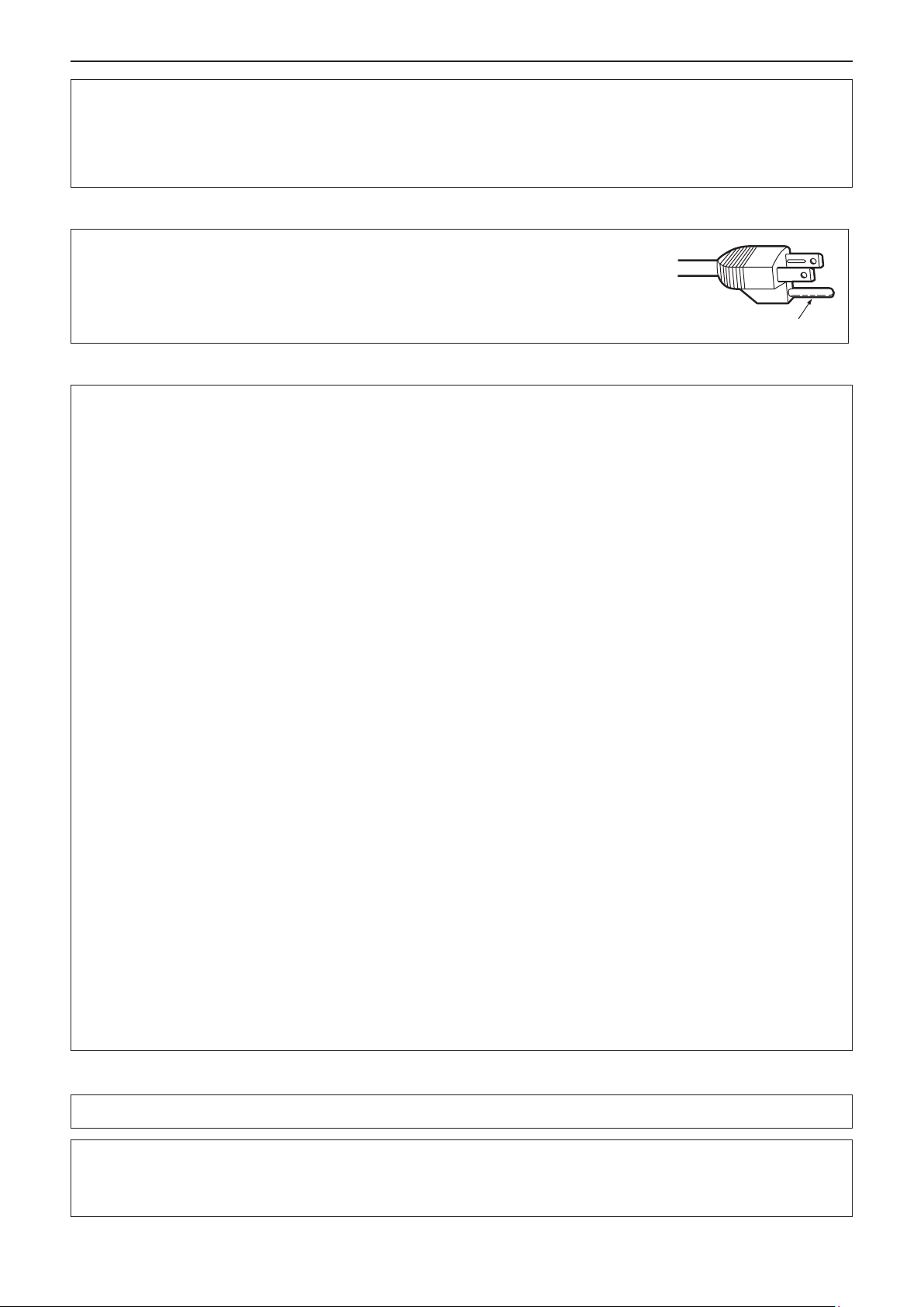
CAUTION (North/Middle/South America)
CAUTION: This equipment is equipped with a three-pin grounding-type power
plug. Do not remove the grounding pin on the power plug. This plug
will only t a grounding-type power outlet. This is a safety feature. If
you are unable to insert the plug into the outlet, contact an electrician.
Do not defeat the purpose of the grounding plug.
Do not remove
FCC NOTICE (USA)
Declaration of Conformity
Model Number: PT-VW350, PT-VX420
Trade Name : Panasonic
Responsible Party : Panasonic Corporation of North America
Address : Two Riverfront Plaza, Newark, NJ 07102-5490
General Contact : http://www.panasonic.com/support
Projector Contact : http://panasonic.net/avc/projector/
This device complies with Part 15 of the FCC Rules.
Operation is subject to the following two conditions:
(1) This device may not cause harmful interference, and (2) this device must accept any interference received,
including interference that may cause undesired operation.
To assure continued compliance, follow the attached installation instructions and do not make any unauthorized
modications.
CAUTION:
This equipment has been tested and found to comply with the limits for a Class B digital device, pursuant
to Part 15 of the FCC Rules. These limits are designed to provide reasonable protection against harmful
interference in a residential installation. This equipment generates, uses and can radiate radio frequency
energy and, if not installed and used in accordance with the instructions, may cause harmful interference to
radio communications. However, there is no guarantee that interference will not occur in a particular installation.
If this equipment does cause harmful interference to radio or television reception, which can be determined
by turning the equipment off and on, the user is encouraged to try to correct the interference by one of the
following measures:
• Reorient or relocate the receiving antenna.
• Increase the separation between the equipment and receiver.
• Connect the equipment into an outlet on a circuit different from that to which the receiver is connected.
• Consult the dealer or an experienced radio/TV technician for help.
The user may nd the booklet “Something About Interference” available from FCC local regional ofces helpful.
FCC Warning:
To assure continued FCC emission limit compliance, follow the attached installation instructions. This includes
using the provided power cord and shielded interface cables when connecting to computer or peripheral
devices. Also, any unauthorized changes or modications to this equipment could void the user’s authority to
operate this device.
NOTIFICATION (Canada)
This class B digital apparatus complies with Canadian ICES-003.
Notice (USA only):
• This product has a High Intensity Discharge (HID) lamp that contains mercury. Disposal may be regulated in your
community due to environmental considerations. For disposal or recycling information, please visit Panasonic website:
http://www.panasonic.com/environmental or call 1-888-769-0149.
ENGLISH - 3
Read this rst!
13A250V
BS1363/A
HE-8
N
ASA
L
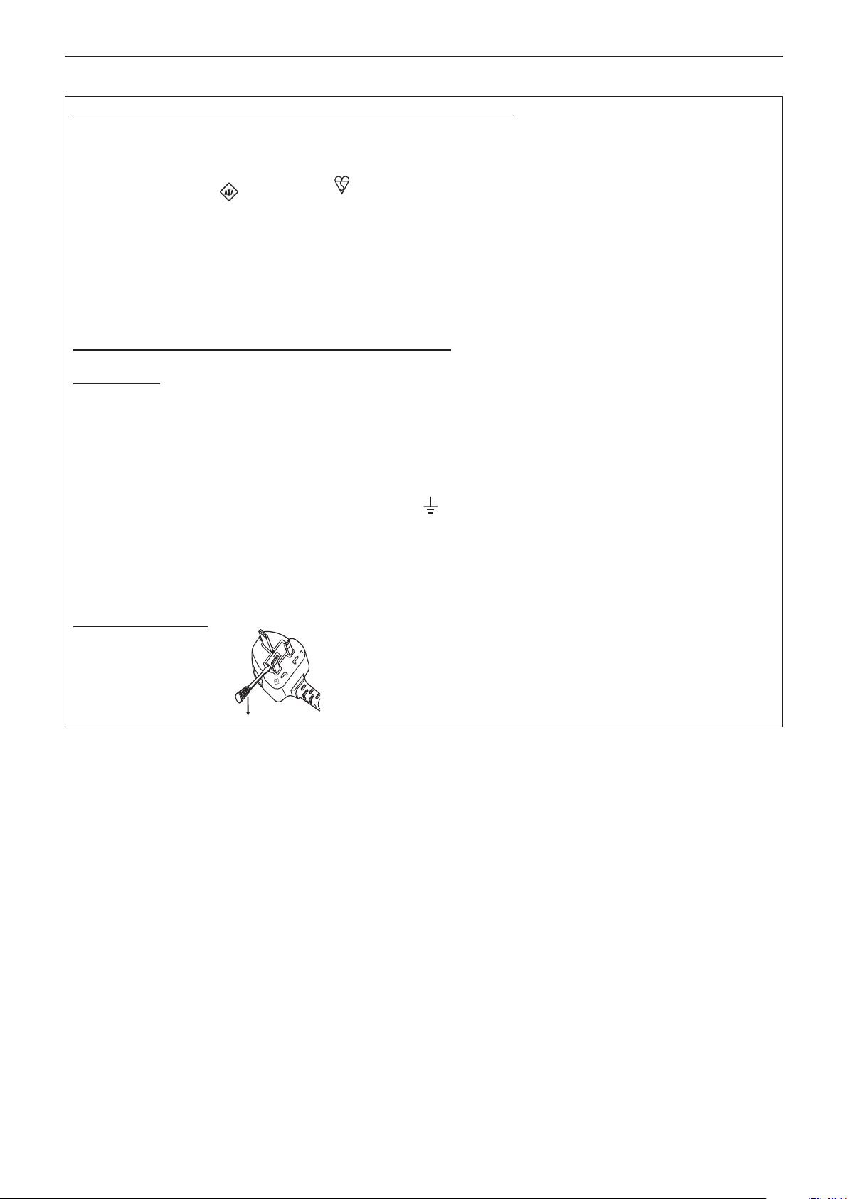
IMPORTANT: THE MOULDED PLUG (U.K. only)
FOR YOUR SAFETY, PLEASE READ THE FOLLOWING TEXT CAREFULLY.
This appliance is supplied with a moulded three pin mains plug for your safety and convenience. A 13 amp fuse is tted in
this plug. Should the fuse need to be replaced, please ensure that the replacement fuse has a rating of 13 amps and that it
is approved by ASTA or BSI to BS1362.
Check for the ASTA mark
If the plug contains a removable fuse cover, you must ensure that it is retted when the fuse is replaced. If you lose the fuse
cover, the plug must not be used until a replacement cover is obtained. A replacement fuse cover can be purchased from an
Authorised Service Center.
If the tted moulded plug is unsuitable for the mains socket in your home, then the fuse should be removed and the plug cut
off and disposed of safely. There is a danger of severe electrical shock if the cut off plug is inserted into any 13 amp socket.
If a new plug is to be tted, please observe the wiring code as shown below.
If in any doubt, please consult a qualied electrician.
WARNING: THIS APPLIANCE MUST BE EARTHED.
IMPORTANT: The wires in this mains lead are coloured in accordance with the following code:
As the colours of the wire in the mains lead of this appliance may not correspond with the coloured markings identifying the
terminals in your plug, proceed as follows.
or the BSI mark on the body of the fuse.
Green - and - Yellow: Earth
Blue: Neutral
Brown: Live
The wire which is coloured GREEN - AND - YELLOW must be connected to the terminal in the plug which is
marked with the letter E or by the Earth symbol
or coloured GREEN or GREEN - AND - YELLOW.
The wire which is coloured BLUE must be connected to the terminal in the plug which is marked with the
letter N or coloured BLACK.
The wire which is coloured BROWN must be connected to the terminal in the plug which is marked with the
letter L or coloured RED.
How to replace the fuse: Open the fuse compartment with a screwdriver and replace the fuse.
4 - ENGLISH
(i)
(ii)
(i)
(ii)
Read this rst!
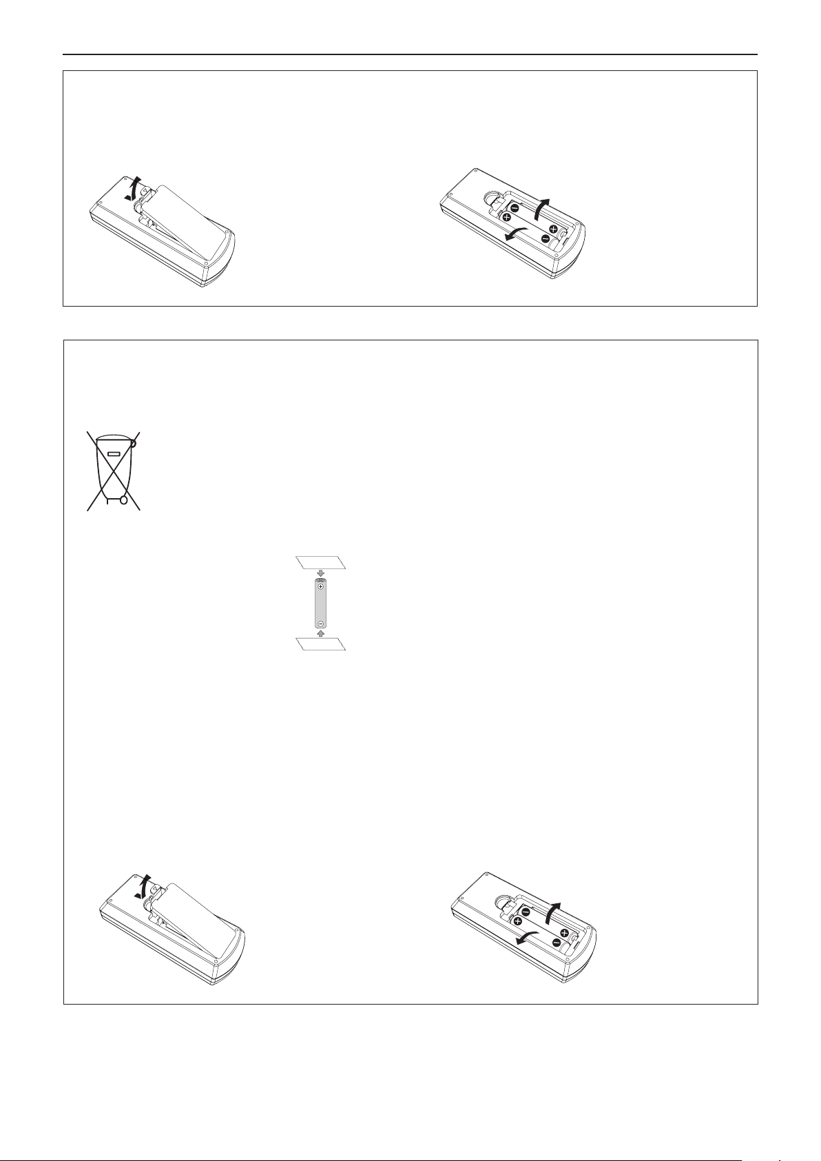
To remove the battery
1. Press the guide and lift the cover. 2. Remove the batteries.
(ii)
(i)
Brazil Only
Brasil Apenas
Manuseio de baterias usadas
BRASIL
Após o uso, as pilhas e /ou baterias deverão
ser entregues ao estabelecimento comercial
ou rede de assistência técnica autorizada.
Cobrir os terminais positivo (+) e negativo (-) com uma ta isolante adesiva, antes de depositar numa caixa
destinada para o recolhimento. O contato entre partes metálicas pode causar vazamentos, gerar calor, romper
a blindagem e produzir fogo.(Fig. 1)
Fig. 1
Como isolar os terminais
Não desmonte, não remova o invólucro, nem amasse a bateria. O gás liberado pela bateria pode irritar a
garganta, danicar o lacre do invólucro ou o vazamento provocar calor, ruptura da blindagem e produzir fogo
devido ao curto circuito dos terminais. Não incinere nem aqueça as baterias, elas não podem car expostas a
temperaturas superiores a 100 °C (212 °F). O gás liberado pela bateria pode irritar a garganta, danicar o lacre
do invólucro ou o vazamento provocar calor, ruptura da blindagem e produzir fogo devido ao curto circuito dos
terminais provocado internamente.
Evite o contato com o liquido que vazar das baterias. Caso isto ocorra, lave bem a parte afetada com bastante
água. Caso haja irritação, consulte um médico.
Fita Isolante
Fita Isolante
Remoção das baterias
1. Pressione a guia e levante a tampa. 2. Remova as baterias.
(ii)
(i)
ENGLISH - 5

Read this rst!
WARNING:
POWER
The wall outlet shall be installed near the equipment and shall be easily accessible when problems
occur. If the following problems occur, disconnect the power plug from the wall outlet immediately.
Continued use of the projector in these conditions will result in re or electric shock.
z If foreign objects or water get inside the projector, disconnect the power plug from the wall outlet.
z If the projector is dropped or the cabinet is broken, disconnect the power plug from the wall outlet.
z If you notice smoke, strange smells or noise coming from the projector, disconnect the power plug from the
wall outlet.
z You have to disconnect the power plug from the wall outlet to cut off the power supply.
Please contact an Authorized Service Center for repairs, and do not attempt to repair the projector yourself.
During a thunderstorm, do not touch the projector or the cable.
Electric shocks can result.
Do not do anything that might damage the power cord or the power plug.
If the power cord is used while damaged, electric shocks, short-circuits or re will result.
zDo not damage the power cord, make any modications to it, place it near any hot objects, bend it
excessively, twist it, pull it, place heavy objects on top of it or wrap it into a bundle.
Ask an Authorized Service Center to carry out any repairs to the power cord that might be necessary.
Completely insert the power plug into the wall outlet and the power connector into the projector
terminal.
If the plug is not inserted correctly, electric shocks or overheating will result.
zDo not use plugs which are damaged or wall outlets which are coming loose from the wall.
Do not use anything other than the provided power cord.
Failure to observe this will result in re or electric shocks. Please note that if you do not use the provided power
cord to ground the device on the side of the outlet, this may result in electric shocks.
Clean the power plug regularly to prevent it from becoming covered in dust.
Failure to observe this will cause a re.
zIf dust builds up on the power plug, the resulting humidity can damage the insulation.
zIf not using the projector for an extended period of time, pull the power plug out from the wall outlet.
Pull the power plug out from the wall outlet and wipe it with a dry cloth regularly.
Do not handle the power plug and power connector with wet hands.
Failure to observe this will result in electric shocks.
Do not overload the wall outlet.
If the power supply is overloaded (ex., by using too many adapters), overheating may occur and re will result.
ON USE/INSTALLATION
Do not place the projector on soft materials such as carpets or sponge mats.
Doing so will cause the projector to overheat, which can cause burns, re or damage to the projector.
Do not set up the projector in humid or dusty places or in places where the projector may come into
contact with oily smoke or steam, ex. a bathroom.
Using the projector under such conditions will result in re, electric shocks or components deterioration. Components deterioration (such as ceiling mount brackets) may cause the projector which is mounted on the ceiling
to fall down.
Do not install this projector in a place which is not strong enough to take the full weight of the projector or on top of a surface which is sloped or unstable.
Failure to observe this will cause projector to fall down or tip over the projector, and severe injury or damage
could result.
Installation work (such as ceiling mount bracket) should only be carried out by a qualied technician.
If installation is not carried out and secured correctly, it can cause injury or accidents, such as electric shocks.
z Be sure to use the wire provided with the ceiling mount bracket as an extra safety measure to prevent the
projector from falling down. (Install in a different location to the ceiling mount bracket.)
Do not cover the air intake/exhaust ports.
Doing so will cause the projector to overheat, which can cause re or damage to the projector.
z Do not place the projector in narrow, badly ventilated places.
z Do not place the projector on cloth or papers, as these materials could be drawn into the air intake port.
z Provide at least 1 m (40") of space between any walls or objects and the exhaust port, and at least 50 cm
(20") of space between any walls or objects and the intake port.
Do not place your hands or other objects close to the air exhaust port.
Doing so will cause burns or damage your hands or other objects.
z Heated air comes out of the air exhaust port. Do not place your hands or face, or objects which cannot
withstand heat close to this port.
6 - ENGLISH

Read this rst!
WARNING:
Do not look at or place your skin into the lights emitted from the lens while the projector is being used.
Doing so can cause burns or loss of sight.
z Strong light is emitted from the projector’s lens. Do not look at or place your hands directly into this light.
z Be especially careful not to let young children look into the lens. In addition, turn off the power and discon-
nect the power plug when you are away from the projector.
Never attempt to remodel or disassemble the projector.
High voltages can cause re or electric shocks.
z For any inspection, adjustment and repair work, please contact an Authorized Service Center.
Do not allow metal objects, ammable objects, or liquids to enter inside of the projector. Do not allow
the projector to get wet.
Doing so may cause short circuits or overheating, and result in re, electric shock, or malfunction of the projector.
z Do not place containers of liquid or metal objects near the projector.
z If liquid enters inside of the projector, consult your dealer.
z Particular attention must be paid to children.
Use the ceiling mount bracket specied by Panasonic.
Using the ceiling mount bracket other than the specied one will result in falling accidents.
z Attach the supplied safety cable to the ceiling mount bracket to prevent the projector from falling down.
ACCESSORIES
Do not use or handle the batteries improperly, and refer to the following.
Failure to observe this will cause burns, batteries to leak, overheat, explode or catch re.
z Do not use unspecied batteries.
z Do not use chargeable batteries.
z Do not disassemble dry cell batteries.
z Do not heat the batteries or place them into water or re.
z Do not allow the + and - terminals of the batteries to come into contact with metallic objects such as neck-
laces or hairpins.
z Do not store or carry batteries together with metallic objects.
z Store the batteries in a plastic bag and keep them away from metallic objects.
z Make sure the polarities (+ and -) are correct when inserting the batteries.
z Do not use a new battery together with an old battery or mix different types of batteries.
z Do not use batteries with the outer cover peeling away or removed.
Do not allow children to reach the batteries.
Accidentally swallowing them can cause physical harm.
z If swallowed, seek medical advice immediately.
If the battery uid leaks, do not touch it with bare hands, and take the following measures if necessary.
z Battery uid on your skin or clothing could result in skin inammation or injury.
Rinse with clean water and seek medical advice immediately.
z Battery uid coming in contact with your eyes could result in loss of sight.
In this case, do not rub your eyes. Rinse with clean water and seek medical advice immediately.
Do not disassemble the lamp unit.
If the lamp breaks, it could cause injury.
Lamp replacement
The lamp has high internal pressure. If improperly handled, an explosion and severe injury or accidents will
result.
z The lamp can easily explode if struck against hard objects or dropped.
z Before replacing the lamp unit, be sure to turn the power off and to disconnect the power plug from the wall
outlet.
Electric shocks or explosions can result if this is not done.
z When replacing the lamp unit, turn the power off and allow the lamp to cool for at least 1 hour before han-
dling it otherwise it can cause burns.
Do not use the supplied power cord with devices other than this projector.
z Using the supplied power cord with devices other than this projector may cause short circuits or overheat-
ing, and result in electric shock or re.
Remove the depleted batteries from the remote control promptly.
z Leaving them in the unit may result in uid leakage, overheating, or explosion of the batteries.
ENGLISH - 7

Read this rst!
CAUTION:
POWER
When disconnecting the power cord, be sure to hold the power plug and power connector.
If the power cord itself is pulled, the lead will become damaged, and re, short-circuits or serious electric
shocks will result.
When not using the projector for an extended period of time, disconnect the power plug from the wall
outlet.
Failure to do so may result in re or electric shock.
Disconnect the power plug from the wall outlet before carrying out any cleaning and replacing the unit.
Failure to do so may result in electric shock.
ON USE/INSTALLATION
Do not place heavy objects on top of the projector.
Failure to observe this will cause the projector to become unbalanced and fall, which could result in damage or
injury. The projector will be damaged or deformed.
Do not put your weight on this projector.
You could fall or the projector could break, and injury will result.
z Be especially careful not to let young children stand or sit on the projector.
Do not place the projector in extremely hot locations.
Doing so will cause the outer casing or internal components to deteriorate, or result in re.
z Take particular care in locations exposed to direct sunlight or near stoves.
Do not place the projector where it may be affected by salt or corrosive gas.
Doing so may cause the projector to become faulty due to corrosion.
Do not place objects in front of the lens while the projector is being used.
Doing so can cause re or damage to the object and can cause the projector to malfunction.
z Extremely strong light is emitted from the projector’s lens.
Do not stand in front of the lens while the projector is being used.
Doing so can cause damage and burns to clothing.
z Extremely strong light is emitted from the projector’s lens.
Always disconnect all cables before moving the projector.
Moving the projector with cables still attached can damage the cables, which will cause re or electric shocks to
occur.
When mounting the projector on the ceiling, keep mounting screws and power cord from contact with
metal parts inside the ceiling.
Contact with metal parts inside the ceiling can cause electric shocks.
Never plug headphones and earphones into <VARIABLE AUDIO OUT> terminal.
Excessive sound pressure from earphones and headphones can cause hearing loss.
ACCESSORIES
Do not use the old lamp unit.
If used it could cause lamp explosion.
If the lamp has broken, ventilate the room immediately. Do not touch or bring your face close to the
broken pieces.
Failure to observe this will cause the user to absorb the gas which was released when the lamp broke and which
contains nearly the same amount of mercury as uorescent lamp, and the broken pieces will cause injury.
z If you believe that you have absorbed the gas or that the gas has got into your eyes or mouth, seek medical
advice immediately.
z Ask your dealer about replacing the lamp unit and check the inside of the projector.
When not using the projector for an extended period of time, remove the batteries from the remote
control.
Failure to observe this will cause the batteries to leak, overheat, catch re or explode, which may result in re
or contamination of surrounding area.
MAINTENANCE
Ask your dealer about cleaning inside the projector once a year.
Continuous use while dust is accumulated inside the projector may result in re.
z For cleaning fee, ask your dealer.
8 - ENGLISH

r Trademarks, etc.
f Windows, Windows Vista and Internet Explorer are registered trademarks or trademarks of Microsoft Corporation in the
United States and other countries.
f Mac, Mac OS, OS X, and Safari are trademarks of Apple Inc., registered in the United States and other countries.
f HDMI, the HDMI logo and High-Denition Multimedia Interface is a trademark or registered trademark of HDMI Licensing
LLC.
f PJLink™ is a trademark or pending trademark in Japan, the United States, and other countries and regions.
f RoomView and Crestron RoomView are registered trademarks of Crestron Electronics, Inc.
Crestron Connected
f Adobe, Adobe Flash Player and Adobe Reader are trademarks or registered trademarks of Adobe Systems Inc. in the United
States and/or other countries.
f Some of the fonts used in the on-screen menu are Ricoh bitmap fonts, which are manufactured and sold by Ricoh Company,
Ltd.
f Other names, company names or product names used in these operating instructions are the trademarks or registered
trademarks of their respective holders.
Please note that the operating instructions do not include the
Software information regarding this product
This product incorporates the following software.
(1) The software which is developed independently by or for Panasonic Corporation
(2) The software owned by third party and licensed to Panasonic Corporation
(3) The software which is licensed under the GNU LESSER GENERAL PUBLIC LICENSE Version2.1 (LGPL V2.1)
The software categorized as (3), the license is available in accordance with gnu lesser general public license, it is distributed
in the hope that it will be useful, but without any warranty, without even the implied warranty of merchantability or tness for a
particular purpose. As for the terms and conditions, please refer to the software license of the supplied CD-ROM.
If you wish to ask any questions as to the software, please contact (sav.pj.gpl.pavc@ml.jp.panasonic.com) by email.
TM
and Fusion RV are trademarks of Crestron Electronics, Inc.
®
and ™ symbols.
r Illustrations in these operating instructions
f Note that illustrations of the projector and screens may differ from the ones you actually see.
r Page references
f In these instructions, references to pages are indicated as: (Æ page 00).
r Term
f In these instructions, the “Wireless remote control unit” accessory is referred to as the “Remote control”.
ENGLISH - 9
Features of the Projector
High Contrast
Quick Steps
For details, see the corresponding pages.
▶ A high contrast of 12 000:1 is achieved by
the unique optical system.
Auto Setup Function
▶ This function executes [SHIFT], [CLOCK
PHASE], [DOT CLOCK] at the same time
by pressing the <AUTO SETUP> button.
Direct Power Off Function
▶ With the Direct Power Off function, you can
disconnect the power cord from the wall
outlet or turn off the breaker even during
projection.
Wired LAN Function
1. Set up your projector.
(x page 26)
2. Connect with other devices.
(x page 30)
3. Connect the power cord.
(x page 35)
4. Power on.
(x page 36)
▶ This function allows you to project an
image on a computer as well as operate
and manage the projector via network.
Useful Functions for Presentations
▶ The digital zoom function allows you to
focus on the crucial information during a
presentation.
▶ The MIC function and 10 W audio output
allows you to make a presentation without
any external audio equipment.
5. Make initial settings.
(x page 36)
f Take this step when you power on for the rst time after
purchasing the projector.
6. Select the input signal.
(x page 40)
7. Adjust the image.
(x page 40)
10 - ENGLISH

Contents
Contents
Contents
Read this first! ............................................2
Chapter 1 Preparation
Precautions for use ................................................. 14
Cautions when transporting .................................. 14
Cautions when installing ....................................... 14
Security ................................................................ 15
Disposal ................................................................ 16
Cautions on use ................................................... 16
Accessories .......................................................... 17
Contents of the supplied CD-ROM ....................... 18
Optional accessories ............................................ 18
About your projector ............................................... 19
Remote control ..................................................... 19
Projector body ...................................................... 20
Preparing the remote control ................................. 23
Inserting and removing batteries .......................... 23
When using the system with multiple projectors .. 23
Attaching the Lens Cap .......................................... 24
Chapter 2 Getting Started
Setting up ................................................................. 26
Installation mode .................................................. 26
Parts for ceiling mount (optional) .......................... 26
Screen size and throw distance ........................... 27
Adjusting adjustable feet ...................................... 29
Connecting ............................................................... 30
Before connecting ................................................ 30
Connecting example : AV equipment ................... 32
Connecting example : Computers ........................ 32
Connecting example : Audio ................................. 33
Chapter 3 Basic Operations
Powering on/off ....................................................... 35
Connecting the power cord .................................. 35
Power indicator ..................................................... 35
Powering On the Projector ................................... 36
When the initial setting screen is displayed .......... 36
Making adjustments and selections ..................... 38
Powering Off the Projector ................................... 39
Direct Power Off function ..................................... 39
Projecting ................................................................. 40
Selecting the input signal ..................................... 40
How to adjust the state of the image .................... 40
Basic operations by using the remote control ..... 41
Using the AUTO SETUP function ......................... 41
Using the KEYSTONE button ............................... 41
Switching the input signal ..................................... 42
Using the FUNCTION button ................................ 42
Using the FREEZE function ................................. 42
Be sure to read “Read this rst!” from page 2.
Using the AV MUTE function ................................ 43
Using the P-TIMER function ................................. 43
Using the DIGITAL ZOOM function ...................... 43
Controlling the volume of the speaker .................. 44
Using the MUTE function ..................................... 44
Using the P IN P function ..................................... 45
Setting the ID number of the remote control ........ 45
Chapter 4 Settings
Menu Navigation ...................................................... 47
Navigating through the menu ............................... 47
Resetting adjustment values to the factory
default ................................................................ 48
Main menu ............................................................ 48
Sub-menu ............................................................. 49
[PICTURE] menu ...................................................... 51
[PICTURE MODE] ................................................ 51
[CONTRAST] ........................................................ 51
[BRIGHTNESS] .................................................... 52
[COLOR] ............................................................... 52
[TINT] ................................................................... 52
[SHARPNESS] ..................................................... 52
[COLOR TEMPERATURE] ................................... 53
[IRIS] .................................................................... 53
[ADVANCED MENU] ............................................ 53
[DAYLIGHT VIEW] ................................................ 53
[DIGITAL CINEMA REALITY] ............................... 54
[NOISE REDUCTION] .......................................... 54
[TV-SYSTEM] ....................................................... 54
[RGB/YP
[POSITION] menu .................................................... 56
[REALTIME KEYSTONE] ..................................... 56
[KEYSTONE] ........................................................ 56
[SHIFT] ................................................................. 58
[DOT CLOCK]....................................................... 58
[CLOCK PHASE] .................................................. 58
[OVER SCAN] ...................................................... 59
[ASPECT] ............................................................. 59
[FRAME LOCK] .................................................... 60
[LANGUAGE] menu ................................................. 61
[LANGUAGE] ....................................................... 61
[DISPLAY OPTION] menu ....................................... 62
[ON-SCREEN DISPLAY] ...................................... 62
[HDMI SIGNAL LEVEL] ........................................ 63
[CLOSED CAPTION SETTING] ........................... 63
[SCREEN SETTING] ........................................... 64
[STARTUP LOGO] ................................................ 64
[AUTO SETUP SETTING] .................................... 65
[SIGNAL SEARCH] .............................................. 65
[BACK COLOR] .................................................... 65
[WIDE MODE] ...................................................... 65
[SXGA MODE] ...................................................... 65
BPR]/[RGB/YCBCR] ................................ 55
ENGLISH - 11

Contents
[P-TIMER] ............................................................. 66
[P IN P] ................................................................. 67
[OTHER FUNCTIONS] ......................................... 67
[PROJECTOR SETUP] menu .................................. 69
[STATUS] .............................................................. 69
[COMPUTER2 SELECT] ...................................... 69
[PROJECTOR ID] ................................................. 69
[INITIAL START UP] ............................................. 70
[PROJECTION METHOD] .................................... 70
[HIGH ALTITUDE MODE] ..................................... 70
[LAMP POWER] ................................................... 71
[ECO MANAGEMENT] ......................................... 71
[EMULATE] ........................................................... 72
[FUNCTION BUTTON] ......................................... 73
[AUDIO SETTING] ............................................... 73
[TEST PATTERN] ................................................. 75
[FILTER COUNTER]............................................. 75
[INITIALIZE ALL] .................................................. 75
[SECURITY] menu ................................................... 76
[PASSWORD] ....................................................... 76
[PASSWORD CHANGE] ...................................... 76
[TEXT DISPLAY] .................................................. 77
[TEXT CHANGE] .................................................. 77
[MENU LOCK] ...................................................... 77
[MENU LOCK PASSWORD] ................................ 77
[CONTROL DEVICE SETUP] ............................... 78
[NETWORK] menu ................................................... 79
[WIRED LAN] ....................................................... 79
[NAME CHANGE] ................................................. 80
[NETWORK CONTROL] ...................................... 80
[AMX D.D.] ........................................................... 80
[Crestron Connected(TM)] .................................... 80
[STATUS] .............................................................. 81
[INITIALIZE] .......................................................... 81
Network connections ............................................ 81
Accessing from the web browser ......................... 83
Specications ........................................................ 114
Dimensions ............................................................ 116
Ceiling mount bracket safeguards....................... 117
Index ....................................................................... 118
Chapter 5 Maintenance
Lamp and Warning Indicators ................................ 98
When an indicator lights up .................................. 98
Maintenance/replacement....................................... 99
Before performing maintenance/replacement ...... 99
Maintenance ......................................................... 99
Replacing the unit ................................................. 99
Troubleshooting .................................................... 103
Chapter 6 Appendix
Technical Information ........................................... 105
PJLink protocol ................................................... 105
Control commands via LAN ................................ 106
Serial terminal .................................................... 108
[MENU LOCK PASSWORD] operations .............110
Two window display combination list ...................111
List of compatible signals ....................................112
12 - ENGLISH

Chapter 1 Preparation
This chapter describes things you need to know or check before using the projector.
ENGLISH - 13
Chapter 1 Preparation - Precautions for use
Precautions for use
Cautions when transporting
f When transporting the projector, hold it securely by its bottom and avoid excessive vibration and impacts. Doing so may
damage the internal parts and result in malfunctions.
f Do not transport the projector with the adjustable feet extended. Doing so may damage the adjustable feet.
Cautions when installing
r Do not set up the projector outdoors.
f The projector is designed for indoor use only.
r Do not use under the following conditions.
f Places where vibration and impacts occur such as in a car or vehicle: Doing so may damage the internal parts and result in
malfunctions.
f Locations near the sea or areas affected by corrosive gas: Corrosion may damage internal components or cause the
projector to malfunction.
f Near the exhaust of an air conditioner: Depending on the conditions of use, the screen may uctuate in rare cases due
to the heated air from the air exhaust port or the hot or cooled air. Make sure that the exhaust from the projector or other
equipment, or the air from the air conditioner does not blow toward the front of the projector.
f Places with sharp temperature uctuations such as near lights (studio lamp): Doing so may shorten the life of the lamp, or
result in deformation of the outer case due to heat, which may cause malfunctions.
The operating environment temperature of the projector should be between 0 °C (32 °F) and 40 °C (104 °F)*
at elevations lower than 1 400 m (4 593') above sea level, and between 0 °C (32 °F) and 30 °C (86 °F) when using it at high
altitudes (between 1 400 m (4 593') and 2 700 m (8 858') above sea level).
*1 When the operating environment temperature of the projector is between 35 °C (95°F) and 40 °C (104 °F), the lamp mode will change to
[ECO] automatically.
f Near high-voltage power lines or near motors: Doing so may interfere with the operation of the projector.
r Be sure to ask a specialized technician when installing the product to a ceiling.
This requires an optional ceiling mount bracket. Be sure to use the Projector Mount Bracket together with the ceiling mount
bracket for high ceilings or low ceilings.
Model No.:
① ET-PKL100H (for high ceilings), ET-PKV400B (Projector Mount Bracket)
② ET-PKL100S (for low ceilings), ET-PKV400B (Projector Mount Bracket)
r Focus adjustment
The projection lens is thermally affected by the light from the light source, making the focus unstable in the period just after
switching on the power. It is recommended that the images are projected continuously for at least 30 minutes before the focus
is adjusted.
r When using the projector in the elevation of below 1 400 m (4 593'), make sure [HIGH ALTITUDE MODE]
is set to [OFF].
Failure to do so may shorten the life of the internal parts and result in malfunctions.
r When using the projector in the elevation of above 1 400 m (4 593') and below 2 000 m (6 562'), make
sure [HIGH ALTITUDE MODE] is set to [HIGH1].
Failure to do so may shorten the life of the internal parts and result in malfunctions.
r When using the projector in the elevation of above 2 000 m (6 562') and below 2 700 m (8 858'), make
sure [HIGH ALTITUDE MODE] is set to [HIGH2].
Failure to do so may shorten the life of the internal parts and result in malfunctions.
r Do not install the projector at elevations of 2 700 m (8 858') or higher above sea level.
Failure to do so may shorten the life of the internal parts and result in malfunctions.
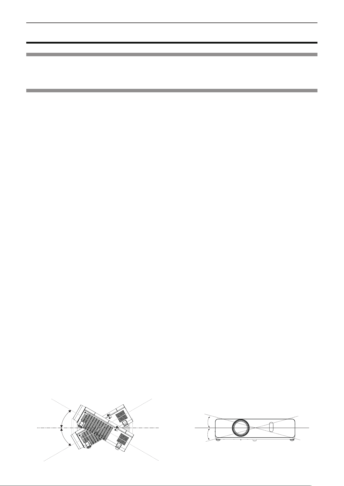
r Do not tilt the projector or place it on its side.
Do not tilt the projector body more than approximately ±40 degrees vertically or ±15 degrees horizontally. Over tilting may
result in shortening the life of the components.
1
when using it
Within 40°
Within 40°
14 - ENGLISH
Within 15°
Within 15°
Chapter 1 Preparation - Precautions for use
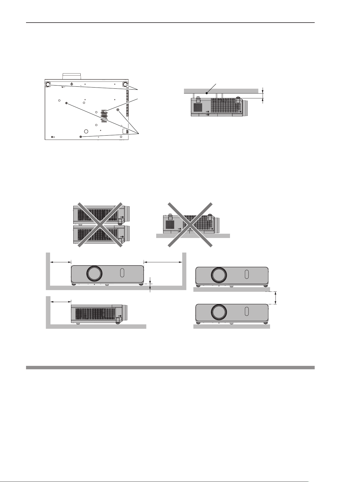
r Cautions when setting the projectors
f If you want to use the projector other than the way of setting on the desk/oor with the adjustable feet or mounting on the
ceiling, use the three screw holes for ceiling mounting (as shown below) to x the projector.
(Screw: M4; Depth of the screw hole: 8 mm (5/16″); Torque: M4 1.25 ± 0.2 N·m)
In addition, always keep a gap of more than 20 mm (25/32″) between the bottom of the projector and installation surface.
Make sure that there is no clearance of at least 20 mm (25/32″) between the screw holes for ceiling mounting and the
installation surface by inserting supports (metallic) between them.
Installation surface
Adjustable feet
Air intake port
(bottom)
fMake sure the air ow into the air intake
port (bottom), failure to do so may cause the
projector cannot work.
The positions of adjustable feet and the
screw holes for ceiling mounting
Screw holes for ceiling
mounting (M4)
f Do not stack the projectors.
f Do not use the projector supporting it by the top.
f Do not block the ventilation ports (intake and exhaust) of the projector.
f Avoid heating and cooling air from the air conditioning system directly blow to the ventilation ports (intake and exhaust) of
the projector.
Over 20 mm
(25/32″)
500 mm (19-11/16")
or longer
500 mm (19-11/16")
or longer
1 000 mm (39-3/8")
or longer
7 mm (9/32")
or longer
200 mm (7-7/8")
or longer
f Do not install the projector in a conned space.
When placing the projector in a conned space, a ventilation and/or air conditioning system is required. Exhaust heat may
accumulate when the ventilation is not enough, triggering the protection circuit of the projector.
Security
Take safety measures against following incidents.
f Personal information being leaked via this product.
f Unauthorized operation of this product by a malicious third party.
f Interfering or stopping of this product by a malicious third party.
Security instruction (x pages 76, 93)
f Make your password as difcult to guess as possible.
f Change your password periodically.
f Panasonic or its afliate company never inquires a password directly to a customer. Do not tell your password in case you
receive such an inquiry.
f The connecting network must be secured by rewall or others.
f Set a password for web control and restrict the users who can log in.
ENGLISH - 15

Chapter 1 Preparation - Precautions for use
Disposal
To dispose of the product, ask your local authorities or dealer for correct methods of disposal.
The lamp contains mercury. When disposing of used lamp units, contact your local authorities or dealer for correct methods of
disposal.
Cautions on use
r To get a good picture quality
f In order to view a beautiful image in higher contrast, prepare an appropriate environment. Draw curtains or blinds over
windows and turn off any lights near the screen to prevent outside light or light from indoor lamp from shining onto the
screen.
r Do not touch the surface of the projector lens with your bare hands.
If the surface of the projection lens becomes dirty from ngerprints or anything else, this will be magnied and projected onto
the screen.
Attach the supplied lens cap to the projection lens when you do not use the projector.
r LCD panel
The LCD panel is precision-made. Note that in rare cases, pixels of high precision could be missing or always lit. Note that
such phenomena do not indicate malfunction. If still images are projected for a long time, a residual image may remain on the
LCD panel. Note that the residual image may not disappear.
r Optical parts
When the operating environment temperature is high or in environments where lots of dust, cigarette smoke, etc. is present,
the replacement cycle of the LCD panel, polarizing plate and other optical parts may be shorter even if used for less than one
year. Consult your dealer for details.
r Lamp
The luminous source of the projector is a mercury lamp with high internal pressure.
A high-pressure mercury lamp has the following characteristics.
f The luminance of the lamp will decrease by duration of usage.
f The lamp may burst with a loud sound or have its service life shortened because of shock, chipping, or degradation due to
cumulative runtime.
f The life of the lamp varies greatly depending on individual specicities and usage conditions. In particular, continuous use
over 12 hours and frequent switching off/on of the power greatly deteriorate the lamp and affect the lamp life.
f In rare cases, the lamp burst shortly after the projection.
f The risk of bursting increases when the lamp is used beyond its replacement cycle. Make sure to replace the lamp unit
consistently. (“When to replace the lamp unit” (x page 101), “Replacing the Lamp unit” (x page 101))
f If the lamp bursts, gas contained inside of the lamp is released in a form of smoke.
f It is recommended to store replacement lamp for contingency.
r Computer and external device connections
f When connecting a computer or an external device, read this manual carefully regarding the use of power cords and
shielded cables as well.
16 - ENGLISH
Chapter 1 Preparation - Precautions for use
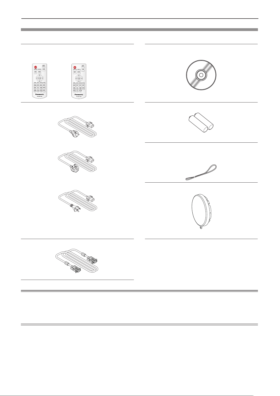
Accessories
Make sure the following accessories are provided with your projector. Numbers enclosed < > show the number of accessories.
Wireless remote control unit <1>
(N2QAYA000071) (N2QAYA000070)
PT-VW350
Power cord
(TXFSX02UXRZ)
(TXFSX02UYAZ)
PT-VX420
CD-ROM <1>
(TXFQB02WYKZ)
AAA/R03 or AAA/LR03 battery <2>
(for remote control unit)
String <1>
(for lens cap)
(6103504711)
(TXFSX02UFEZ) Lens cap <1>
(TKKL5568)
RGB signal cable <1>
(K1HY15YY0012)
Attention
f After unpacking the projector, discard the power cord cap and packaging material properly.
f Do not use the supplied power cord for devices other than this projector.
f For lost accessories, consult your dealer.
f Store small parts in an appropriate manner, and keep them away from young children.
Note
f The type and number of the power cord depend on the country in which you purchased the product.
f The model numbers of accessories are subject to change without prior notice.
f The supplied string is used for lens cap, refer to “Attaching the Lens Cap” (x page 24).
ENGLISH - 17
Chapter 1 Preparation - Precautions for use
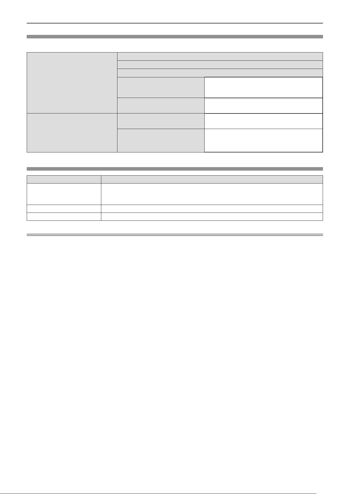
Contents of the supplied CD-ROM
The contents of the supplied CD-ROM are as follow.
Operating Instructions – Functional Manual
Operating Instructions – Multi Projector Monitoring & Control Software
Operating Instructions – Logo Transfer Software
Instruction / list (PDF)
Software
List of compatible projector models
Software license
Multi Projector Monitoring & Control
Software (Windows)
Logo Transfer Software (Windows)
Optional accessories
Options Model No.
ET-PKL100H (for high ceilings)
Ceiling Mount Bracket
Replacement Lamp Unit ET-LAV300
Replacement Filter Unit ET-RFV300
ET-PKL100S (for low ceilings)
ET-PKV400B (Projector Mount Bracket)
This is a list of projectors that are compatible
with the software contained in the CD-ROM and
their restrictions.
The open source software licenses that used in
this projector are included in the PDF les.
This software allows you to monitor and control
multiple projectors connected to the LAN.
This software allows you to transfer original
images, such as company logos to be displayed
when projection starts, to the projector.
Note
f The model numbers of optional accessories are subject to change without prior notice.
18 - ENGLISH
Chapter 1 Preparation - About your projector
About your projector
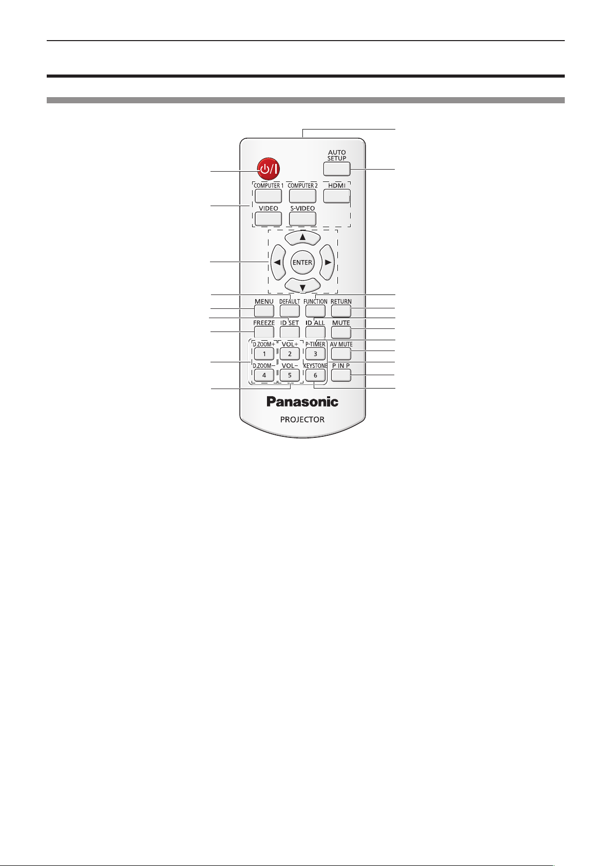
Remote control
20
1
19
2
3
4
5
6
7
18
17
16
15
14
13
8
12
11
9
10
1 Power <v/b> button
Turn the projector on or off. (x pages 36, 39)
(v standby / b power on)
2 Input Selection Buttons: <COMPUTER 1>,
<COMPUTER 2>, <HDMI>, <VIDEO>, <S-VIDEO>
These buttons are used to select the input signal.
(x page 40)
3 asqw Buttons, <ENTER> Button
Navigate the MENU display.
4 <DEFAULT> Button
Resets the content of the sub-menu to the factory default
(x page 48). Or deletes one character when you enter
an IP address or a text.
5 <MENU> Button
Open or close the On-Screen Menu. (x page 47)
6 <ID SET> Button
Sets the ID number of the remote control to use for a
system using multiple projectors. (x page 23)
7 <FREEZE> Button
Pauses the projected image and mute the audio
temporarily. (x page 42)
8 <D.ZOOM +/-> Buttons
Zoom in and out the images. (x page 43)
9 <VOL +/-> Buttons
Adjust the volume of the speaker. (x page 44)
10 <KEYSTONE> Button
Correct keystone distortion. (x page 41)
11 <P IN P> Button (Only for PT-VW350)
Operate the P IN P function.
12 Number buttons
Act as number buttons. Use these buttons when setting
the remote control codes or entering the password.
13 <AV MUTE> Button
Used to turn off the audio and video temporarily.
(x page 43)
14 <P-TIMER> Button
Operate the P-timer function. (x page 43)
15 <MUTE> Button
Used to mute the audio. (x page 44)
16 <ID ALL> Button
Used to simultaneously control all the projectors with
one remote control for a system using multiple projectors.
(x page 23)
17 <RETURN> Button
Return to the previous menu or cancel the setting.
18 <FUNCTION> Button
Assigns a frequently used operation as a shortcut button.
19 <AUTO SETUP> Button
Automatically adjusts the image display position while
projecting the image. (x page 41)
20 Remote control signal emitter
ENGLISH - 19
Chapter 1 Preparation - About your projector
Attention
f Do not drop the remote control.
f Avoid contact with liquids.
f Do not attempt to modify or disassemble the remote control.
f Please observe the following contents that are described on
the back of the remote control unit (see the right picture).
1. Do not use a new battery together with an old battery.
2. Do not use unspecied batteries.
1.Do not use old battery with new one.
2.Do not use batteries other than the
type specified.
3.Be sure the batteries are inserted properly.
3. Make sure the polarities (+ and -) are correct when inserting the batteries.
f In addition, please read the contents that are related to batteries in the “Read this rst!”.
Note
f The remote control can be used within a distance of about 7 m (22'11-5/8") if pointed directly at the remote control signal
receiver. The remote control can control at angles of up to ± 30 ° vertically and ± 30 ° horizontally, but the effective control
range may be reduced.
f If there are any obstacles between the remote control and the remote control signal receiver, the remote control may not
operate correctly.
f You can operate the projector by reecting the remote control signal on the screen. The operating range may differ due to
the loss of light caused by the properties of the screen.
f When the remote control signal receiver is lit with a uorescent light or other strong light source, the projector may become
inoperative. Set the projector as far from the luminous source as possible.
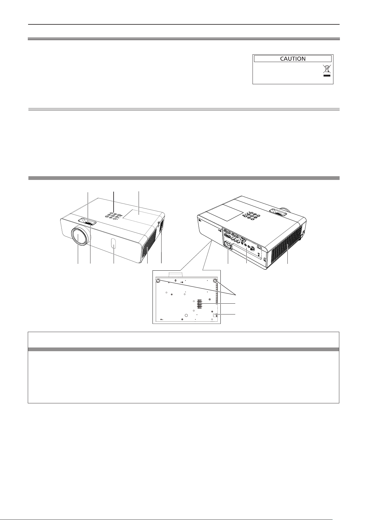
Projector body
1 2
5
4
6
3
7 8
9
10 11
12
13
14
WARNING
Keep your hands and other objects away from the air exhaust port and the air intake port (bottom).
f Keep your hand and face away.
f Do not insert your nger.
f Keep heat-sensitive articles away.
Heated air from the air exhaust port can cause burns or external damage.
When using the projector on a ceiling and powering off with the Direct Power Off function, the heated air from the air intake
port in the bottom can cause burns or external damage.
1 Zoom ring (Back)
Adjust the zoom.
2 Control Panel and Indicators (x page 21)
3 Lamp cover (x page 101)
The lamp unit is located inside.
4 Projection Lens
5 Focus ring (Front)
Adjust the focus.
6 Remote control signal receiver
7 Air exhaust port
8 Speaker
20 - ENGLISH
9 <AC IN> terminal
Con
nect the supplied power cord.
10 Connecting terminals (x page 22)
11 Air intake port (Side) / Air lter cover (x page 99)
The air lter unit is inside.
12 Adjustable feet
Ad
just the projection angle.
13 Air intake port (Bottom)
14 Security Chain Hook
Attaches a burglar prevention cable, etc.

Chapter 1 Preparation - About your projector
Attention
f Do not block the ventilation ports (intake and exhaust) of the projector.
r Control panel and Indicators
1
2
3
4
5
1 Power <v/b> button
Turns the projector on/off.
(v standby / b power on)
2 Power indicator <ON(G)/STANDBY(R)>
Displays the status of the power.
3 Lamp indicator <LAMP>
Displays the status of the lamp.
4 Warning indicator <WARNING>
Indicates the abnormal conditions of the projector.
5 Ambient Luminance sensor
Detects room's light and select proper image
quality.
9
10
7
6
8
6 <MENU> button
Displays the menu screen. (x page 47)
7 <ENTER> button
Determines and executes an item in the menu
screen.
8 asqw buttons
Navigates the MENU screen.
Adjusts the volume level (qw).
9 <INPUT SELECT> button
Selects the input signal for projection.
(x page 40)
10 <AUTO SETUP> button
Executes the auto setup function.
ENGLISH - 21
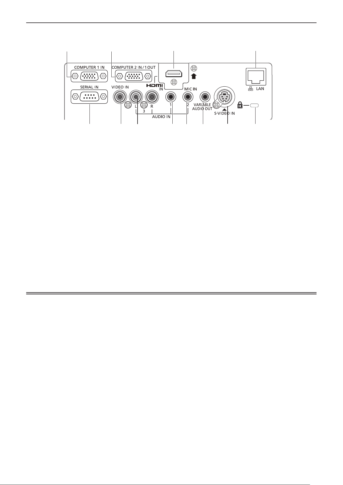
r Connecting terminals
Chapter 1 Preparation - About your projector
1
5 6 7
1 <COMPUTER 1 IN> terminal
This is the terminal to input RGB or YCBCR/YPBPR
signals.
2 <COMPUTER 2 IN/ 1 OUT> terminal
This is the terminal to input RGB signals.
Or output the RGB or YC
external monitor.
3 <HDMI IN> terminal
This is the terminal to input HDMI signals.
4 <LAN> terminal
This is the LAN terminal to connect to the network.
5 <SERIAL IN> terminal
This is the RS-232C compatible terminal to
externally control the projector by connecting a
computer.
6 <VIDEO IN> terminal
This is the terminal to input video signals.
2
/YPBPR signals to
BCR
3 4
9
8
7 <AUDIO IN 3 (L/R)> terminal
8 <AUDIO IN 1> terminal
9 <AUDIO IN 2 (MIC IN)> terminal
10 <VARIABLE AUDIO OUT> terminal
11 <S-VIDEO IN> terminal
12 Security slot
10
This is the terminal to input audio signals.
Left input (L) and right input (R) are provided for
the <AUDIO IN 3> terminal.
This is the terminal to input audio signals.
This is the terminal to input audio signals.
Or connect the MIC to this terminal.
This is the terminal to output the input audio signal
to the projector.
This is the terminal to input s-video signals.
Attach the commercial shackle lock, manufactured
by Kensington, to protect your projector.
Compatible with the Kensington MicroSaver
Security System.
11
12
Attention
f When a LAN cable is directly connected to the projector, the network connection must be made indoors.
22 - ENGLISH
(i)
(ii)
Chapter 1 Preparation - Preparing the remote control
Preparing the remote control
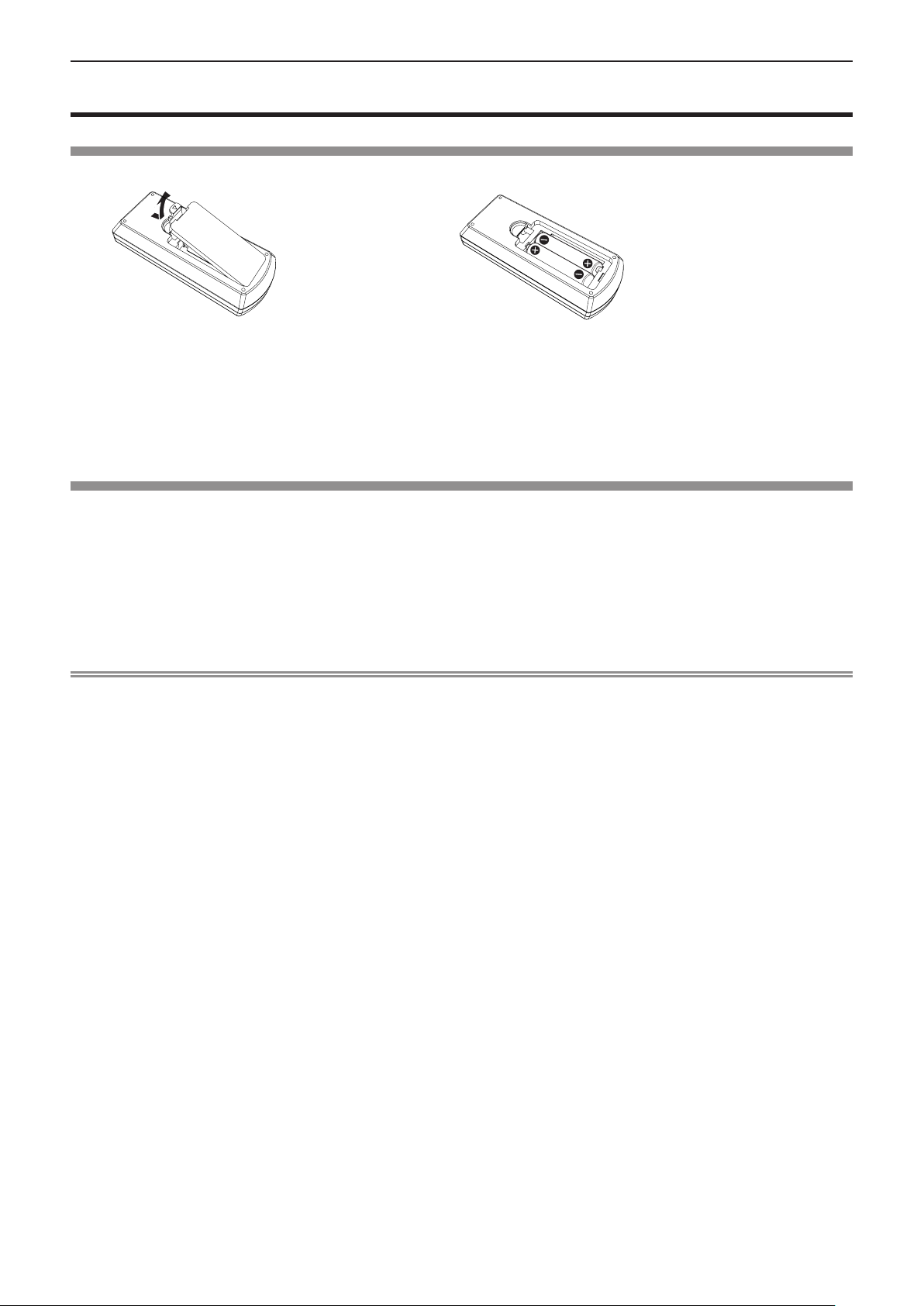
Inserting and removing batteries
(ii)
(i)
Fig. 1
Fig. 2
1) Open the cover. (Fig. 1)
2) Insert batteries and close the cover. (Insert the m side first.) (Fig. 2)
f When removing the batteries, perform the steps in reverse order.
When using the system with multiple projectors
When you use the system with multiple projectors, you can operate all the projectors simultaneously or each projector
individually by using single remote control, if a unique ID number is assigned to each projector.
When you want to set the ID number, at rst you need to complete the Initial setting, and then after setting the ID number of
the projector, set the ID number on the remote control. About Initial setting, please refer to “When the initial setting screen is
displayed” (x page 36).
The factory default ID number of the unit (the projector and the remote control) is set to [ALL], you can control with this setting.
If necessary, please set the ID number to the remote control and the projector. About how to set the ID number of the remote
control, please refer to “Setting the ID number of the remote control” (x page 45).
Note
f Set the ID number of the projector from the [PROJECTOR SETUP] menu → [PROJECTOR ID]. (x page 69)
ENGLISH - 23
Chapter 1 Preparation - Attaching the Lens Cap
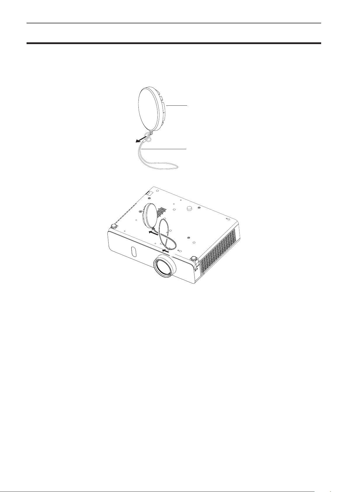
Attaching the Lens Cap
When moving this projector or while not using it over an extended period of time, attach the lens cap.
To prevent loss for the lens cap, please according to the following procedures, attach the lens cap with the string of
accessories.
1) Thread the thinner end of the string through the hole on the lens cap.
Lens cap
String
2) Thread the other end of the string through the hole on the bottom of the projector.
(ii)
(i)
24 - ENGLISH

Chapter 2 Getting Started
This chapter describes things you need to do before using the projector such as the setup and
connections.
ENGLISH - 25
Chapter 2 Getting Started - Setting up
Setting up
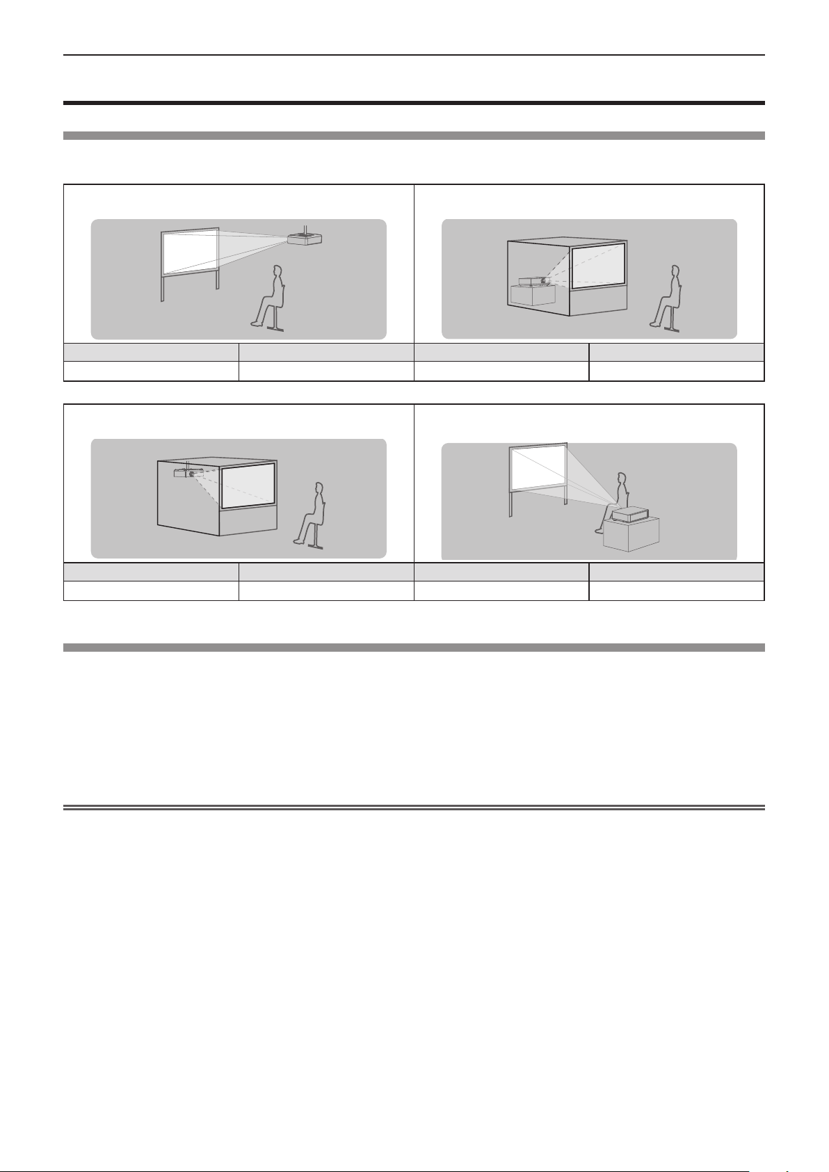
Installation mode
There are four ways to set up the projector. Set the [PROJECTOR SETUP] menu → [PROJECTION METHOD] (x page 70)
depending on the installation location.
Mounting on the ceiling and projecting forward
Menu item Method Menu item Method
[PROJECTION METHOD] [FRONT/CEILING] [PROJECTION METHOD] [REAR/DESK]
Setting on a desk/oor and projecting from rear
(Using the translucent screen)
Mounting on the ceiling and projecting from rear
(Using the translucent screen)
Menu item Method Menu item Method
[PROJECTION METHOD] [REAR/CEILING] [PROJECTION METHOD] [FRONT/DESK]
Setting on a desk/oor and projecting forward
Parts for ceiling mount (optional)
This requires an optional ceiling mount bracket. Be sure to use the Projector Mount Bracket together with the ceiling mount
bracket for high ceilings or low ceilings.
Model No.:
① ET-PKL100H (for high ceilings), ET-PKV400B (Projector Mount Bracket)
② ET-PKL100S (for low ceilings), ET-PKV400B (Projector Mount Bracket)
f Use only the ceiling mount brackets specied for this projector.
f Refer to the Installation Instructions for the ceiling mount bracket when you install the bracket and the projector.
Attention
f To ensure projector performance and security, installation of the ceiling mount bracket must be carried by your dealer or a
qualied technician.
26 - ENGLISH
Chapter 2 Getting Started - Setting up
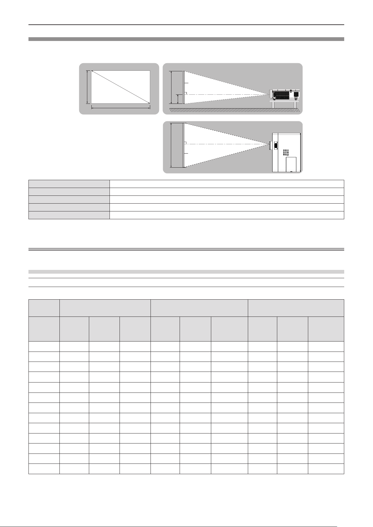
Screen size and throw distance
Refer to the screen size and projection distances to install the projector. Image size and image position can be adjusted in
accordance with the screen size and screen position.
Projected image
SD
SH
SW
SH
H
SW
L (LW/LT) *
*1 LW : Minimum distance
LT : Maximum distance
1
SH Image height (m)
SW Image width (m)
H Distance from the center of lens to the image lower end (m)
SD Projected image size (m)
Projection distance (m)
Attention
f Before installing, please read “Precautions for Use” (x page 14).
Screen
L (LW/LT)
L (LW/LT)
Screen
Projection distance
For PT-VW350
All measurements below are approximate and may differ slightly from the actual measurements. (Unit: m)
Projection
size
Screen
diagonal
(SD)
0.76 (30") 0.83 1.37 0.009 0.76 1.24 -0.012 0.73 1.21 0.008
1.02 (40") 1.13 1.85 0.012 1.02 1.68 -0.017 0.99 1.63 0.011
1.27 (50") 1.41 2.31 0.015 1.28 2.09 -0.021 1.25 2.04 0.013
1.52 (60") 1.70 2.77 0.018 1.54 2.51 -0.025 1.50 2.44 0.016
1.78 (70") 1.99 3.25 0.021 1.81 2.95 -0.029 1.76 2.87 0.019
2.03 (80") 2.28 3.71 0.024 2.07 3.37 -0.033 2.01 3.27 0.022
2.29 (90") 2.57 4.19 0.027 2.33 3.80 -0.037 2.27 3.70 0.024
2.54 (100") 2.86 4.65 0.030 2.59 4.22 -0.041 2.52 4.10 0.027
3.05 (120") 3.44 5.59 0.037 3.12 5.07 -0.050 3.03 4.93 0.032
3.81 (150") 4.30 6.99 0.046 3.90 6.34 -0.062 3.80 6.17 0.040
5.08 (200") 5.74 9.33 0.061 5.21 8.47 -0.083 5.07 8.24 0.054
6.35 (250") 7.19 11.67 0.076 6.52 10.59 -0.104 6.34 10.30 0.067
7.62 (300") 8.63 14.01 0.091 7.82 12.72 -0.124 7.62 12.37 0.081
For 4:3 aspect ratio For 16:9 aspect ratio For 16:10 aspect ratio
Minimum
distance
(LW)
Maximum
distance
(LT)
Height
position
(H)
Minimum
distance
(LW)
Maximum
distance
(LT)
Height
position (H)
Minimum
distance
(LW)
Maximum
distance
(LT)
Height
position (H)
ENGLISH - 27
Chapter 2 Getting Started - Setting up
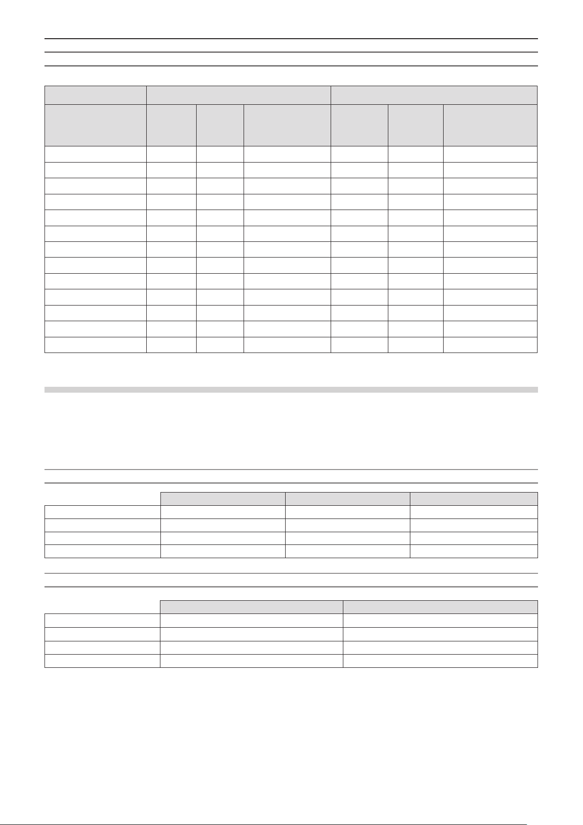
For PT-VX420
All measurements below are approximate and may differ slightly from the actual measurements. (Unit: m)
Projection size For 4:3 aspect ratio For 16:9 aspect ratio
Minimum
Screen diagonal (SD)
0.76 (30") 0.69 1.14 0.046 0.75 1.24 -0.012
1.02 (40") 0.94 1.54 0.061 1.02 1.68 -0.017
1.27 (50") 1.17 1.92 0.076 1.28 2.09 -0.021
1.52 (60") 1.41 2.30 0.091 1.54 2.51 -0.025
1.78 (70") 1.65 2.70 0.107 1.81 2.94 -0.029
2.03 (80") 1.89 3.08 0.122 2.06 3.36 -0.033
2.29 (90") 2.14 3.48 0.137 2.33 3.80 -0.037
2.54 (100") 2.37 3.87 0.152 2.59 4.21 -0.041
3.05 (120") 2.86 4.65 0.183 3.11 5.07 -0.050
3.81 (150") 3.58 5.81 0.229 3.90 6.33 -0.062
5.08 (200") 4.78 7.76 0.305 5.21 8.45 -0.083
6.35 (250") 5.98 9.70 0.381 6.52 10.57 -0.104
7.62 (300") 7.18 11.65 0.457 7.82 12.70 -0.124
distance
(LW)
Maximum
distance
(LT)
Height position (H)
Minimum
distance
(LW)
Maximum
distance
(LT)
Projection distance formulas
Height position (H)
Any other projection distance can be obtained according to the screen dimensions (m) by using the following calculations.
The calculated distance may contain a certain error.
If you want to calculate the projection distance with projected image size SD (unit: inch) by substituting, please assign 0.0254
times to the SD value.
For PT-VW350
For 4:3 aspect ratio For 16:9 aspect ratio For 16:10 aspect ratio
Screen height (SH) = 0.6 × SD(m) = 0.490 × SD(m) = 0.530 × SD(m)
Screen width (SW) = 0.8 × SD(m) = 0.872 × SD(m) = 0.848 × SD(m)
Minimum distance (LW) = 1.1363 × SD(m) - 0.0290 = 1.0316 × SD(m) - 0.0290 = 1.0037 × SD(m) - 0.0290
Maximum distance (LT) = 1.8422 × SD(m) - 0.0292 = 1.6725 × SD(m) - 0.0292 = 1.6273 × SD(m) - 0.0292
For PT-VX420
For 4:3 aspect ratio For 16:9 aspect ratio
Screen height (SH) = 0.6 × SD(m) = 0.490 × SD(m)
Screen width (SW) = 0.8 × SD(m) = 0.872 × SD(m)
Minimum distance (LW) = 0.9461 × SD(m) - 0.0295 = 1.0307 × SD(m) - 0.0295
Maximum distance (LT) = 1.5324 × SD(m) - 0.0272 = 1.6696 × SD(m) - 0.0272
28 - ENGLISH
Chapter 2 Getting Started - Setting up
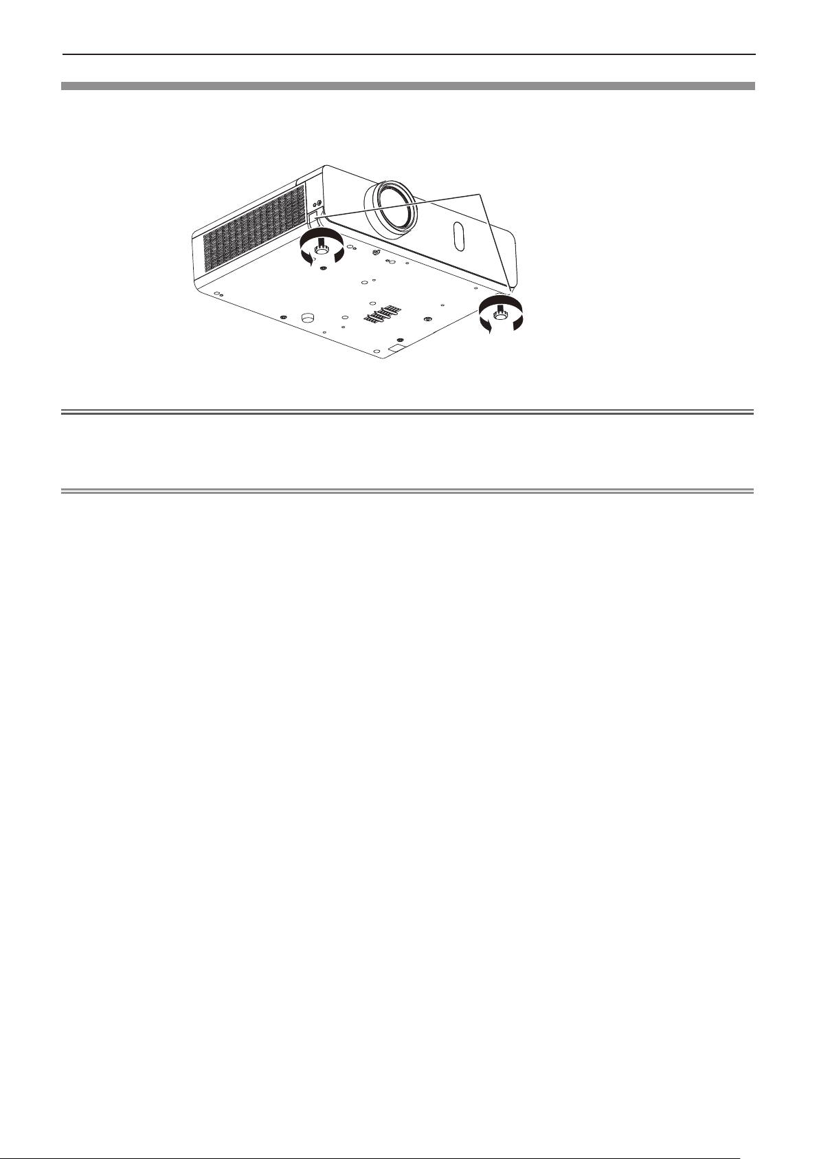
Adjusting adjustable feet
Lift the front of the projector and press the feet lock latches on both side of the projector.
Release the feet lock latches to lock the adjustable feet and rotate the adjustable feet to a proper height and tilt.
Extend the adjustable feet by rotating in the direction shown in the gure and retract by rotating in the opposite direction.
Feet lock latches
Adjustable range
Adjustable feet : 43 mm (1-11/16")
Attention
f Heated air comes out of the air exhaust port while the lamp is lit. Do not touch the air exhaust port directly when you adjust
the adjustable feet.
f If keystone distortion occurs on the projected image, perform [KEYSTONE] from the [POSITION] menu. (x page 56)
Note
f Screw up the adjustable feet, and an audible click will be heard as the limit.
ENGLISH - 29
Chapter 2 Getting Started - Connecting
Connecting
Before connecting
f Before connecting, carefully read the operating instructions for the external device to be connected.
f Turn off the power switch of the devices before connecting cables.
f Take note of the following points before connecting the cables. Failure to do so may result in malfunctions.
- When connecting a cable to a device connected to the projector or the projector itself, touch any nearby metallic objects to
eliminate static electricity from your body before performing work.
- Do not use unnecessarily long cables to connect to a device connected to the projector or to the projector body. The longer
the cable, the more it is susceptible to noise. Since using a cable while it is wound makes it act like an antenna, it is more
susceptible to noise.
- When connecting cables, connect GND rst, then insert the connecting terminal of the connecting device in a straight
manner.
f If any connection cable is not supplied with the device, or if no optional cable is available for connection of the device,
prepare a necessary system connection cable to suit the device.
f Video signals containing too much jitter may cause the images on the screen to randomly wobble or wafture.
In this case, a time base corrector (TBC) must be connected.
f The projector accepts VIDEO signals, S-VIDEO signals, YC
are TTL level), and digital signal.
f Some computer models or graphics cards are not compatible with the projector.
f When using long cables to connect with each of equipment to the projector, there is a possibility that the image will not be
output correctly unless a compensator is used.
f For details on what video signals the projector supports, see “List of compatible signals”. (x page 112)
/YPBPR signals and analog RGB signals (synchronous signals
BCR
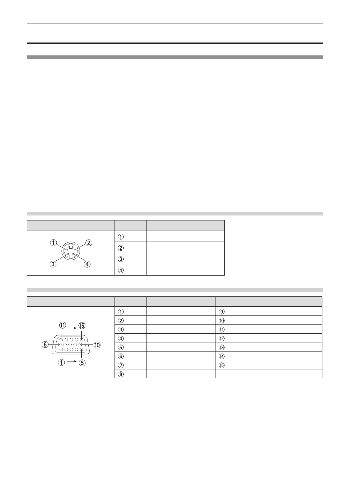
<S-VIDEO IN> terminal pin assignments and signal names
Outside view
Pin No. Signal names
GND (luminance signal)
GND (color signal)
Luminance signal
Color signal
<COMPUTER 1 IN> terminal pin assignments and signal names
Outside view
Pin No. Signal names Pin No. Signal names
R/P
R
G/Y
B/P
B
— DDC data
GND HD/SYNC
GND VD
GND DDC clock
GND
+ 5 V
GND
GND
30 - ENGLISH
 Loading...