


Operating Instructions
DLP® Based Projector
Commercial Use
Models No.
PT-D10000U
PT-DW10000U
Read these instructions completely before operating this unit.
TQBJ 0208

Dear Panasonic Customer:
This instruction booklet provides all the necessary operating information that you might require. We hope it will help
you to get the most performance out of your new product, and that you will be pleased with your Panasonic DLP®
based projector.
The serial number of your product may be found on its back. You should note it in the space provided below and
retain this booklet in case service is required.
Model number: PT-D10000U/PT-DW10000U
Serial number:
2 – ENGLISH

Contents
IMPORTANT SAFETY NOTICE .............................................................................................4
Precautions with regard to safety ........................................................................................ 6
Before Using ........................................................................................................................ 10
Location and function of each part ....................................................................................12
Using the remote control unit ............................................................................................17
Installation ............................................................................................................................19
Connection ........................................................................................................................... 24
Installation of input module (optional) .............................................................................. 27
How to install and remove the projection lens (optional) ................................................33
Projection ............................................................................................................................. 34
How to adjust the lens ........................................................................................................37
Automatic adjustment (AUTO SETUP) .............................................................................. 39
Registration of input signal data ........................................................................................40
Basic operations using the remote control ......................................................................43
On-screen menus ................................................................................................................46
Adjusting the picture ...........................................................................................................49
Adjusting the position .........................................................................................................56
How to use ADVANCED MENU ..........................................................................................60
Setting the DISPLAY LANGUAGE ...................................................................................... 66
Be sure to read the “IMPORTANT SAFETY NOTICE” and
the “Precautions with regard to safety”. (pp. 4-9)
Getting StartedGetting Started
Basic OperationSpecial FeaturesInformation
Option1 settings .................................................................................................................. 67
Option2 settings .................................................................................................................. 75
Displaying the internal test pattern ...................................................................................83
How to use network function .............................................................................................84
Using the PJLink™ protocol ..............................................................................................98
Setting the security ............................................................................................................. 99
Using the serial terminals ................................................................................................. 102
Using the Remote 2 terminal ............................................................................................ 106
Indication of monitor lamp ...............................................................................................107
Cleaning and replacement of air filter ............................................................................. 108
Replacement of lamp unit ................................................................................................. 110
Notes when installing the ceiling mount bracket ........................................................... 112
Before asking for service
Self-diagnosis display....................................................................................................... 114
Specifications .................................................................................................................... 116
Appendix ............................................................................................................................ 118
Dimensions ........................................................................................................................ 120
Index ................................................................................................................................... 121
Français Information ......................................................................................................... 123
… try to check the following points again. ........................................... 113
ENGLISH – 3
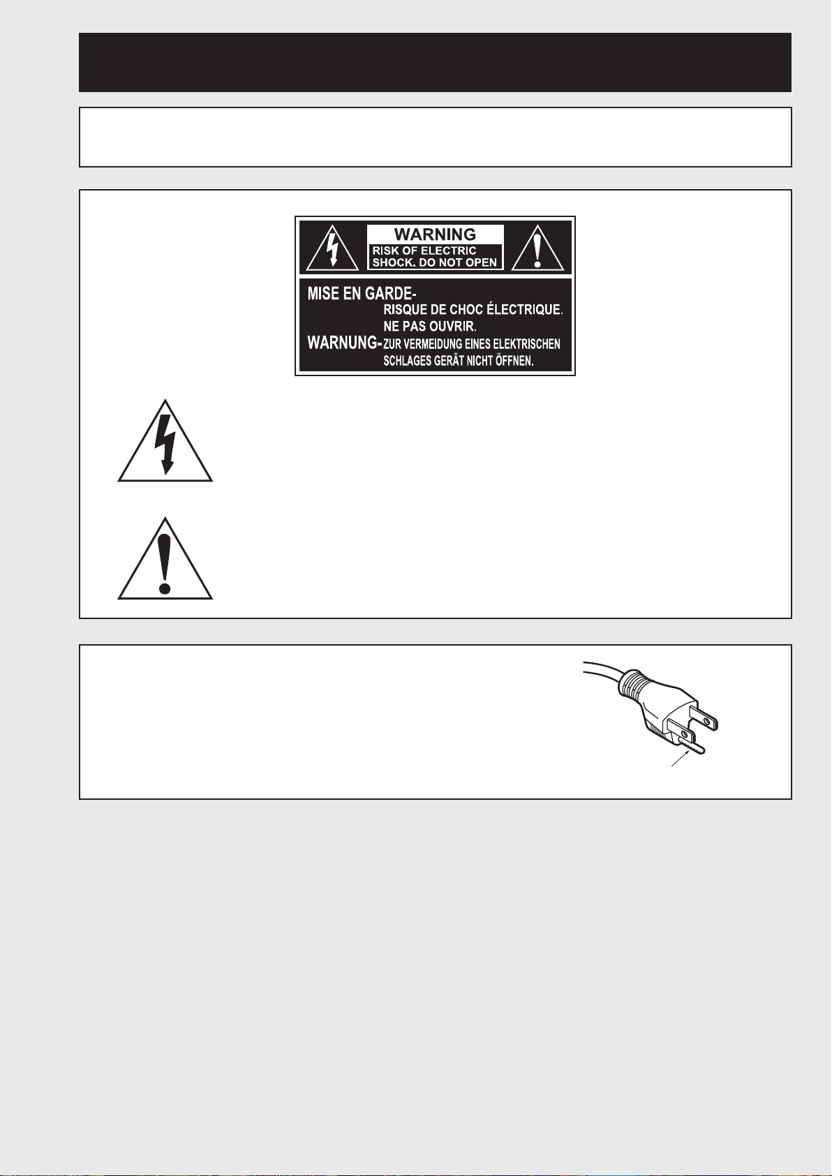
IMPORTANT SAFETY NOTICE
WARNING: TO REDUCE THE RISK OF FIRE OR ELECTRIC SHOCK, DO NOT EXPOSE
THIS PRODUCT TO RAIN OR MOISTURE.
The lightning flash with arrowhead symbol, within an equilateral triangle,
is intended to alert the user to the presence of uninsulated “dangerous
voltage” within the Product’s enclosure that may be of sufficient magnitude
to constitute a risk of electric shock to persons.
The exclamation point within an equilateral triangle is intended to alert the
user to the presence of important operating and maintenance (servicing)
instructions in the literature accompanying the product.
CAUTION:
This equipment is equipped with a three-pin grounding-type power plug.
Do not remove the grounding pin on the power plug. This plug will only fit
a grounding-type power outlet. This is a safety feature. If you are unable
to insert the plug into the outlet, contact an electrician. Do not defeat the
purpose of the grounding plug.
Do not remove
4 – ENGLISH
WARNING: This equipment has been tested and found to comply with the limits for a
Class B digital device, pursuant to part 15 of the FCC Rules. These limits
are designed to provide reasonable protection against harmful interference
in a residential installation. This equipment generates, uses and can radiate
radio frequency energy and, if not installed and used in accordance with
the instructions, may cause harmful interference to radio communications.
However, there is no guarantee that interference will not occur in a particular
installation. If this equipment does cause harmful interference to radio or
television reception, which can be determined by turning the equipment off and
on, the user is encouraged to try to correct the interference by one or more of
the following measures:
– Reorient or relocate the receiving antenna.
– Increase the separation between the equipment and receiver.
– Connect the equipment into an outlet on a circuit different from that to which
the receiver is connected.
– Consult the dealer or an experienced radio/TV technician for help.
FCC CAUTION: To assure continued compliance, use only shielded interface cables when
connecting to computer or peripheral devices. Any unauthorized changes or
modifications to this equipment could void the user’s authority to operate.
Getting Started
WARNING: Not for use in a computer room as defined in the Standard for the Protection of
Electronic Computer/Data Processing Equipment, ANSI/NFPA 75.
Declaration of Conformity
Model Number: PT-D10000U / PT-DW10000U
Trade Name: Panasonic
Responsible Party: Panasonic North America
Address: One Panasonic Way 4B-9 Secaucus, NJ 07094
Telephone Number: 1-800-524-1448 or 1-800-526-6610
Email: pjscservice@us.panasonic.com
This device complies with Part 15 of the FCC Rules. Operation is subject to the following
two conditions: (1) This device may not cause harmful interference, and (2) this device must
accept any interference received, including interference that may cause undesired operation.
NOTICE: This product has a High Intensity Discharge (HID) lamp that contains a small
amount of mercury. It also contains lead in some components. Disposal of these
materials may be regulated in your community due to environmental considerations.
For disposal or recycling information please contact your local authorities, or the
Electronics Industries Alliance: <http://www.eiae.org.>
ENGLISH – 5

Precautions with regard to safety
WARNING
If a problem occurs (such as no image) or if you notice smoke or
■
a strange smell coming from the projector, turn off the power and
disconnect the power cord from the wall outlet.
• Do not continue to use the projector in such cases, otherwise fire or electric shocks could result.
• Check that no more smoke is coming out, and then contact an Authorized Service Center for repairs.
• Do not attempt to repair the projector yourself, as this can be dangerous.
Do not install this projector in a place which is not strong enough to
■
take the full weight of the projector.
• If the installation location is not strong enough, it may fall down or tip over, and severe injury or
damage could result.
• Installation work (such as ceiling suspension) should only be carried out by a qualified technician.
• If installation is not carried out correctly, there is the danger that injury or electric shocks may occur.
If foreign objects or water get inside the projector, or if the projector
■
is dropped or the cabinet is broken, turn off the power and disconnect
the power cord from the wall outlet.
• Continued use of the projector in this condition may result in fire or electric shocks.
• Contact an Authorized Service Center for repairs.
Do not cover the air filter, the air inlet and exhaust vents.
■
• Doing so may cause the projector to overheat, which can cause fire or damage to the projector.
Do not overload the wall outlet.
■
• If the power supply is overloaded (for example, by using too many adapters), overheating may occur
and fire may result.
Do not remove the cover or modify it in any way.
■
• High voltages which can cause fire or electric shocks are present inside the projector.
• For any inspection, adjustment and repair work, please contact an Authorized Service Center.
Clean the power cord plug regularly to prevent it from becoming
■
covered in dust.
• If dust builds up on the power cord plug, the resulting humidity can damage the insulation, which could
result in fire. Pull the power cord out from the wall outlet and wipe it with a dry cloth.
• If not using the projector for an extended period of time, pull the power cord plug out from the wall
outlet.
Do not do anything that might damage the power cord or the power
■
cord plug.
• Do not damage the power cord, make any modifications to it, place it near any hot objects, bend it
excessively, twist it, pull it, place heavy objects on top of it or wrap it into a bundle.
• If the power cord is used while damaged, electric Shocks, short-circuits or fire may result.
• Ask an Authorized Service Center to carry out any repairs to the power cord that might be necessary.
Do not handle the power cord plug with wet hands.
■
• Failure to observe this may result in electric shocks.
6 – ENGLISH

Insert the power cord plug securely into the wall outlet.
■
• If the plug is not inserted correctly, electric shocks or overheating could result.
• Do not use plugs which are damaged or wall outlets which are coming loose from the wall.
■
Do not place the projector on top of surfaces which are unstable.
• If the projector is placed on top of a surface which is sloped or unstable, it may fall down or tip over,
and injury or damage could result.
Do not place the projector into water or let it become wet.
■
• Failure to observe this may result in fire or electric shocks.
Do not disassemble the lamp unit.
■
• If the lamp section breaks, it may cause injury.
Do not place liquid containers on top of the projector.
■
• If water spills onto the projector or gets inside it, fire or electric shocks could result.
• If any water gets inside the projector, contact an Authorized Service Center.
Do not insert any foreign objects into the projector.
■
• Do not insert any metal objects or flammable objects into the projector or drop them onto the projector,
as doing so can result in fire or electric shocks.
After removing the battery from remote control unit, keep it away from
■
the reach of children.
• The battery can cause death by suffocation if swallowed.
• If the battery is swallowed, seek medical advice immediately.
Getting Started
Do not allow the + and - terminals of the battery to come into contact
■
with metallic objects such as necklaces or hairpins.
• Failure to observe this may cause the battery to leak, overheat, explode or catch fire.
• Store the battery in a plastic bag and keep it away from metallic objects.
Insulate the battery using tape or similar before disposal.
■
• If the battery comes into contact with metallic objects or other batteries, it may catch fire or explode.
■
Replacement of the lamp unit should be carried out by a qualified
technician.
• The lamp unit has high internal pressure. If improperly handled, failure might result.
• The lamp unit can easily become damaged if struck against hard objects or dropped, and injury or
malfunctions may result.
■
When installing to a ceiling, be sure to use the accessory wire (install
in a different location to the ceiling mount bracket) and the eye bolts
as an extra preventative measure to stop the projector from falling
down.
• If the projector is not secure enough, accidents may result.
■
Do not place sets directly on top of each other.
• If this is not observed, accidents may result.
Do not use the projector while the projection lens cover is still
■
attached to the projection lens (sold separately).
• If this is not observed, fire may occur.
ENGLISH – 7

Precautions with regard to safety (continued)
CAUTION
Do not set up the projector in humid or dusty places or in places
■
where the projector may come into contact with smoke or steam.
• Using the projector under such conditions may result in fire or electric shocks.
■
When disconnecting the power cord, hold the plug, not the cord.
• If the power cord itself is pulled, the cord will become damaged, and fire, short-circuits or serious
electric shocks may result.
■
Always disconnect all cables before moving the projector.
• Moving the projector with cables still attached can damage the cables, which could cause fire or electric
shocks to occur.
Do not place any heavy objects on top of the projector.
■
•
Failure to observe this may cause the projector to become unbalanced and fall, which could result in damage
or injury.
Do not short-circuit, heat or disassemble the battery or place it into
■
water or fire.
• Failure to observe this may cause the battery to overheat, leak, explode or catch fire, and burns or
other injury may result.
When inserting the battery, make sure the polarities (+ and -) are
■
correct.
• If the battery is inserted incorrectly, it may explode or leak, and fire, injury or contamination of the
battery compartment and surrounding area may result.
■
Use only the specified battery.
• If an incorrect battery is used, it may explode or leak, and fire, injury or contamination of the battery
compartment and surrounding area may result close to this port, otherwise burns or damage could
result.
■
Do not look into the lens while the projector is being used.
•
Strong light is emitted from the projector’s lens. If you look directly into this light, it can hurt and damage your
eyes.
■
Do not place your skin into the light beam while the projector is being
used.
• Strong light is emitted from the projector’s lens. If you place directly into this light, it can hurt or damage
your skin.
■
Do not bring your hands or other objects close to the air outlet port.
•
Heated air comes out of the air outlet port. Do not bring your hands or face, or objects which cannot
withstand heat.
■
Do not use the old lamp unit.
• The lamp section may break.
■
Replacement of the lamp unit should only be carried out after it has
completely cooled off, otherwise burns may result.
8 – ENGLISH

Disconnect the power cord plug from the wall outlet as a safety
■
precaution before carrying out any cleaning.
• Electric shocks can result if this is not done.
■
If the lamp has broken, ventilate the room immediately. Do not touch
or bring your face close to the broken pieces.
• Failure to observe this may cause the user to absorb the gas which was released when the lamp broke
and which contains nearly the same amount of mercury as fluorescent lamps, and the broken pieces
may cause injury.
• If you believe that you have absorbed the gas or that the gas has got into your eyes or mouth, seek
medical advice immediately.
• Ask your dealer to replace the lamp unit and check the inside of the projector.
■
Ask an Authorized Service Center to clean inside the projector at least
once a year.
• If dust is left to build up inside the projector without being cleaned out, it can result in fire or problems
with operation.
• It is a good idea to clean the inside of the projector before the season for humid weather arrives. Ask
your nearest Authorized Service Center to clean the projector when required. Please discuss with the
Authorized Service Center regarding cleaning costs.
Do not reach for the openings beside the optical lens, during
■
horizontal or vertical movements of the lens there is a injury hazard.
Getting Started
An effort to keep our environment clean, please bring the non
■
repairable unit your Dealer or a Recycling Company.
■
Do not use projectors with the adjustable feet or projection lens cover
removed.
• If this is not observed, the sets may not operate correctly or accidents may result.
ENGLISH – 9
Before Using
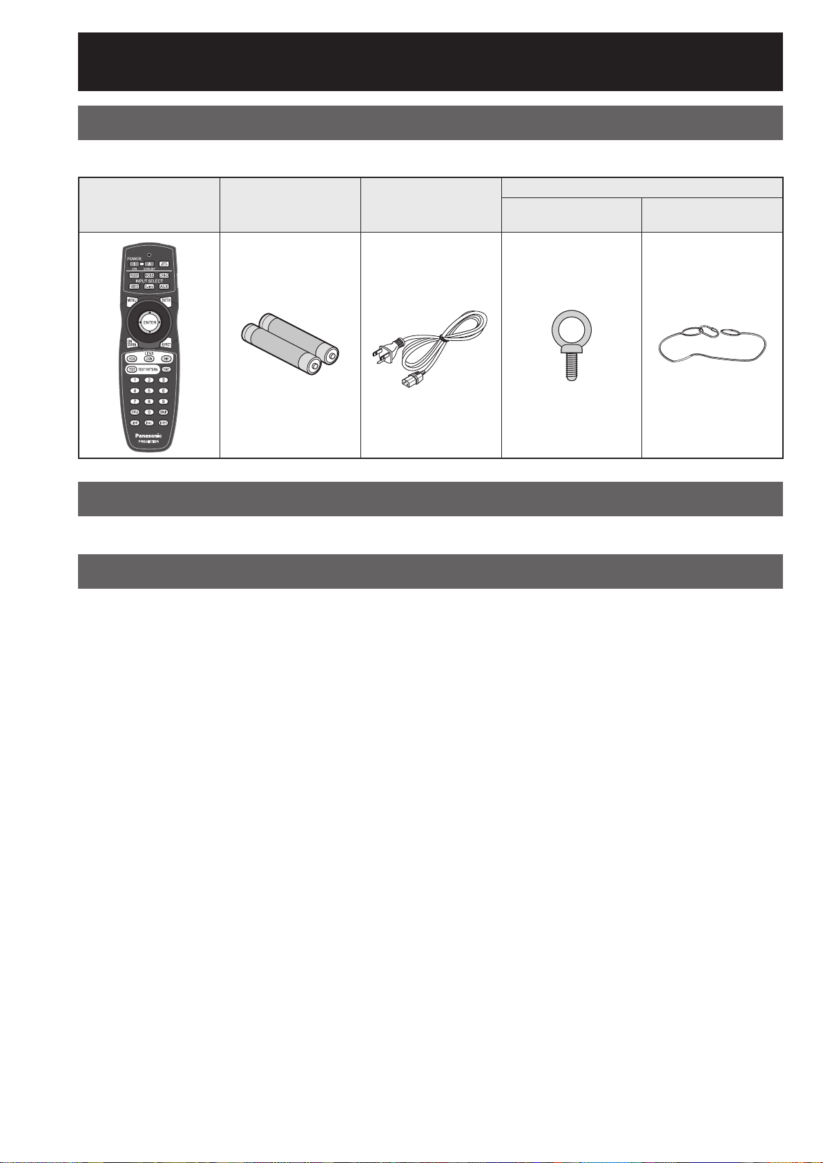
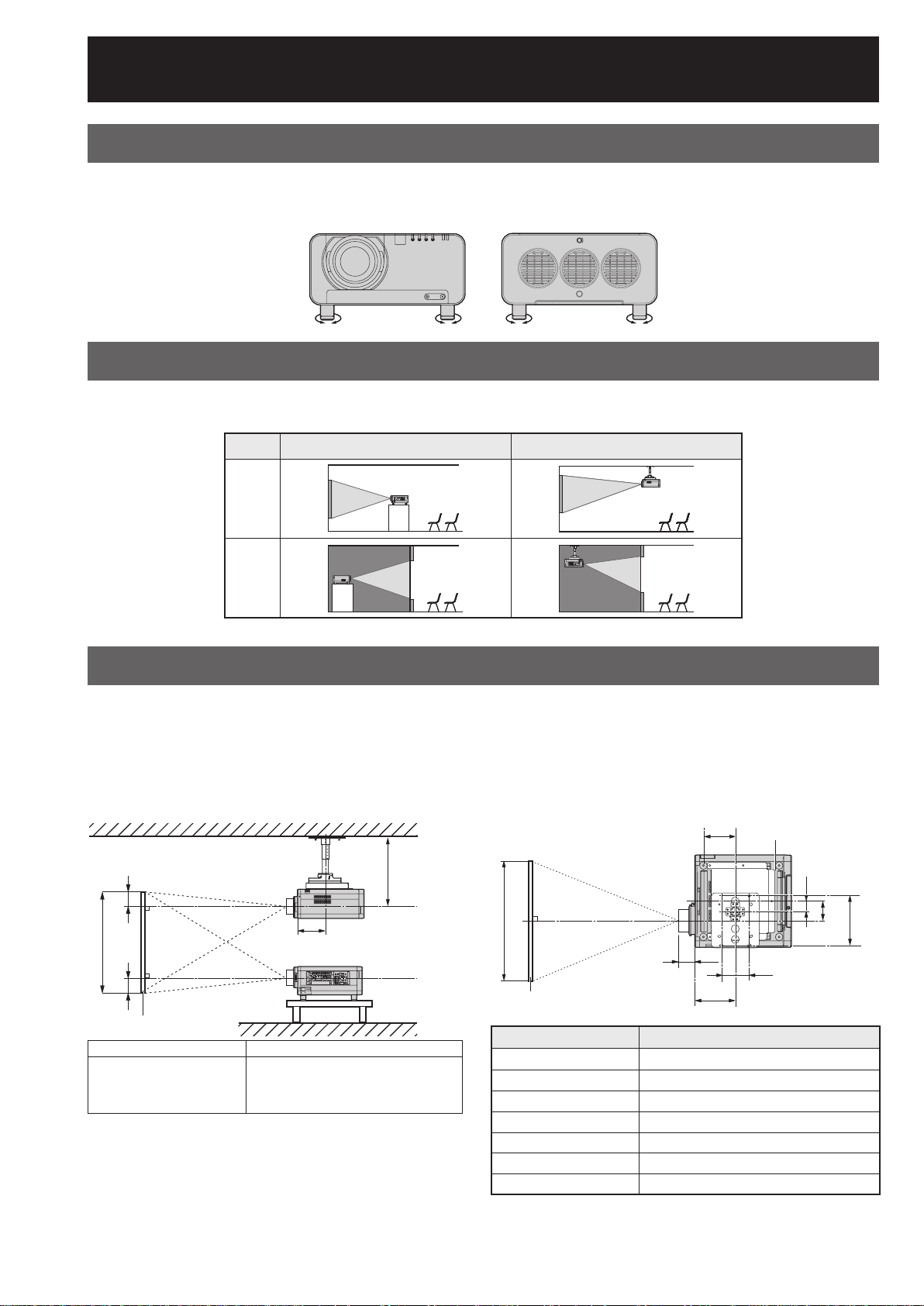
Accessories
Check that all of the accessories shown below have been included with your projector.
Remote Control
[N2QAYB000076 × 1]
Batteries for Remote
Control (AA)
Power cord
[K2CG3YY00015 × 1]
[THEA172J × 4]
Drop-prevention bracket
Eye bolt
Wire
[TTRA0144 × 4]
Caution when moving the projector
The projection lens is susceptible to vibrations and impacts. Be sure to always remove the lens during transport.
Cautions regarding setup
Be sure to observe the following precautions when installing the product.
Be sure to install the projection lens cover when installing the projection
■
lens.
If this is not done, dust will collect inside the projector and problems with the projector will result.
Avoid installing the product in a place exposed to vibrations or impacts.
■
If the projector is installed in a place where vibrations are transmitted from a source of driving power and
others or mounted in a car, vibrations or impacts may be transmitted to the product to damage the internal
parts, causing failure. Install the product in a place free from vibrations and impacts.
Do not install the projector near high-voltage power lines or power sources.
■
The product may be exposed to interference if it is installed in the vicinity of high-voltage electrical power lines
or power sources.
Do not place the projector on a vinyl sheet or carpet.
■
If a vinyl sheet sucked up and blocks the air filter intake port, the internal temperature of the projector may
increase, which triggers the protection circuit, turning off the power.
Be sure to ask a specialized technician when to install the product to a
■
ceiling.
If the product is to be installed hanging from the ceiling, purchase an optional hanging attachment (for high
ceiling: Model No. ET-PKD100H) (for low ceiling: Model No. ET-PKD100S) and call a specialized technician for
installation.
Do not place the projector over 2 700 m (8881.5´) above sea level. When
■
using it over 1 400 m (4605.3´) above sea level, set the “
described on
Otherwise the life of the product may be shortened.
10 – ENGLISH
ALTITUDE”,
page 76, to “HIGH”.

Notes on use
To view clear images:
■
● The audience cannot enjoy high-contrast and clear images if outside light or the illumination interferes the
screen surface. Draw window curtains or blinds, turn off the lightings near the screen or take other proper
measures.
● In rare cases, wafture can occur on the screen affected by the warm air from the exhaust port depending on
the environment. Make sure that there is no equipment in front of the set which will recirculate the exhaust
air from the set or other nearby equipment.
Do not touch the surface of the projection lens with bare hand.
■
If fingerprints or stains are left on the projection lens surface, they are magnified and projected on the screen.
Keep your hands away from the lens. Cover the lens with the supplied lens cap when the projector is not used.
Screen
■
If the screen has stains, flaws or discoloration, clear images cannot be viewed. When handling the screen, be
careful not to apply volatile substances or leave flaws or stains on the screen.
■
Lamp
A mercury lamp with high internal pressure is used for the light source of this product. A high-pressure mercury
lamp has the following characteristics:
● It may burst with a loud sound or end its life cycle by not illuminating because of given impacts, flaws, or
deterioration due to used hours.
● The life cycle of a mercury lamp varies according to the individual difference or conditions of use. In
particular, turning the power on and off frequently and/or repeatedly will greatly affect the life cycle.
● In rare cases, it may burst shortly after the first lighting.
● The possibility of burst increases when the lamp is used beyond the replacement time.
■
Maintenance
Be sure to remove the power cord plug from the receptacle before cleaning.
● Use soft and dry cloth to clean the cabinet
Use a soft cloth moistened in warm water to clean away oil. If a chemical wipe is used, follow its
instructions.
● Do not clean the lens surface with fuzzy or dusty cloth.
If dust adheres to the lens, it will be magnified and projected on the screen. Use a soft and clean cloth to
wipe off dust.
Getting Started
Disposal
To discard the product, call the dealer or a specialized dealer.
ENGLISH – 11
Location and function of each part
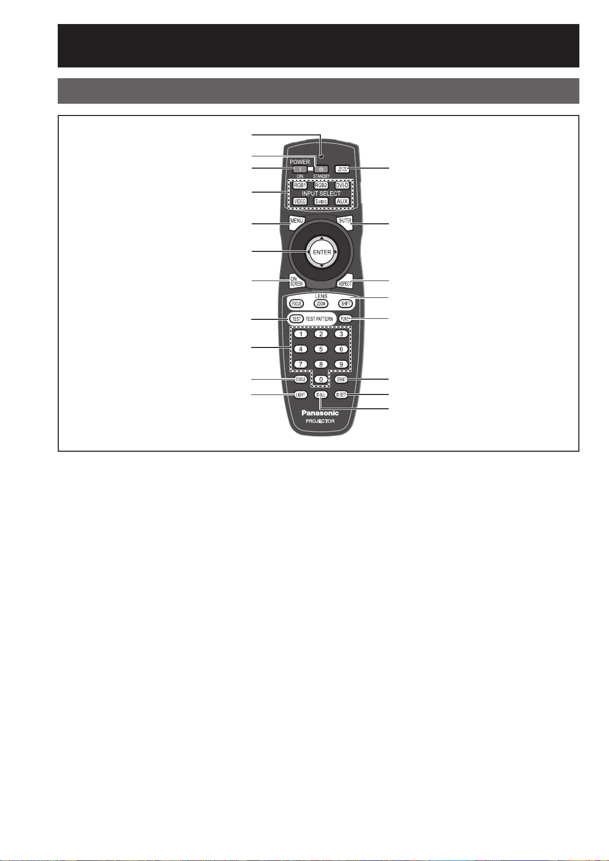
Remote control unit
Front■
#
$
%
&
(
)
*
+
-
.
/
0
1
2
3
4
5
6
7
# Remote control operation indicator lamp
The lamp flashes when any remote control button
is pressed.
$ POWER
When the projector is in projection mode with the
MAIN POWER switch of the projector at the “ l ”
side, this button switches the projector to standby
mode.
% POWER ON button ............................. (pp. 34, 35)
When the projector is in standby mode with the
MAIN POWER switch of the projector at the “ l ”
side, this button switches the projector to projection
mode.
& Input select (RGB1, RGB2, DVI-D, VIDEO,
S-VIDEO, AUX) button ................................ (
Use to change the RGB1, RGB2, DVI-D, VIDEO,
S-VIDEO and AUX (module input) input ports.
( MENU button ....................................... (
Displays and clears the Main Menu. It can also
return to the previous screen when the menu is
displayed.
) Arrow▲▼◄►buttons ........................(
Use these buttons to select an item on the menu
screen, change setting and adjust the level.
Also use them to enter the “SECURITY” password.
ENTER button ............................................. (p. 48)
Press this button to enter your menu selection or to
run function.
STANDBY button ................. (pp. 34, 36)
p. 43)
pp. 46, 48)
pp. 48, 99)
* ON SCREEN button .................................... (p. 43)
This button turns on and off the on-screen
indication function.
+ TEST PATTERN button .............................. (
This displays the test pattern.
- Numeric (0-9) buttons ........................ (pp. 18, 82)
These buttons are used for systems where more
than one projector is being used. They are used to
enter ID numbers when selecting an ID, and they
are also used by service personnel for entering
passwords when password entry is needed.
. STATUS button ........................................... (
Press this button to display projector information.
It can also be used to send information about the
projector’s status via E-mail.
/ LIGHT button .............................................. (
When this button is pressed, the remote control
button light is turned on. The light goes off
about 10 seconds after you stop remote control
operation.
0 AUTO SET UP button ................................. (
Pressing this button while projecting an image
automatically corrects the picture positioning on
the screen. While the auto setup feature is active,
a message “PROGRESS...” appears on the
screen.
p. 44)
p. 43)
p. 44)
p. 44)
12 – ENGLISH
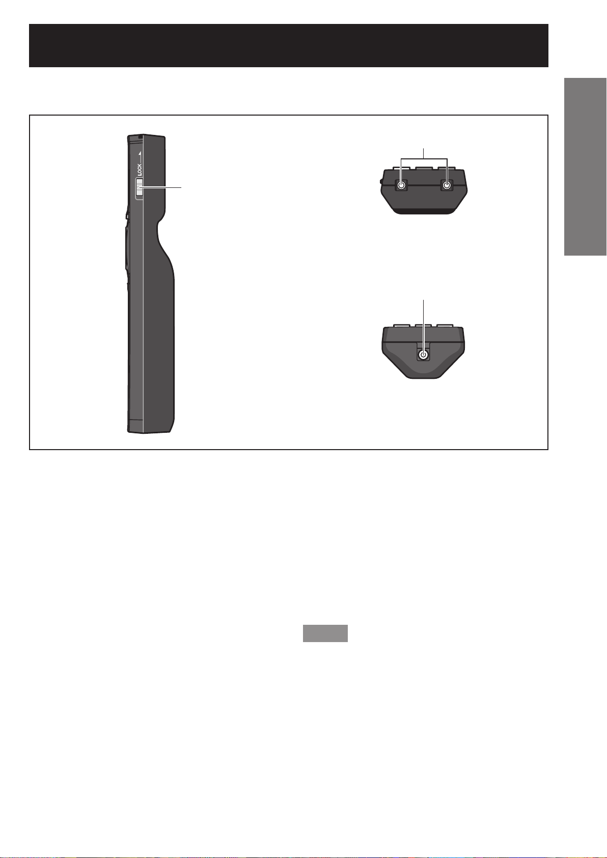
Side■ Top■
8
9
Getting Started
Bottom■
:
1 SHUTTER button ........................................ (p. 43)
Press this button to black out the image
temporarily.
2 ASPECT button ........................................... (
Switches the image aspect ratio.
3 LENS (FOCUS, ZOOM, SHIFT) button ......(p. 37)
These buttons are used to adjust the projection
lens.
4 Function 1 (FUNC1) button ........................ (
This button can control the functions set in
“FUNC1” of the “OPTION1” screen from MAIN
MENU.
5 DEFAULT button ........................................ (
Press this button to restore the default factory
setting.
6 ID SET button ......................................(
When two or more main units are used in the
system, this button specifies the ID of the remote
control.
7 ID ALL button ......................................(pp. 18, 75)
When two or more main units are used in the
system, this button switches to the mode to control
them simultaneously with a single remote control.
p. 45)
p. 44)
p. 48)
pp. 18, 75)
8 LOCK button
This button is used to prevent unintentional
operation of the projector by accidentally pressing
a button, and to prevent the remote control
batteries from becoming spent.
9 Remote control transmitter window
Operate the remote control aiming at the remote
control receiver window on the main unit.
: Remote control wired terminal .................. (
To use the wired output terminal, connect the
remote control and the main unit with the cable
(sold separately).
p. 18)
Note
The AUX button to switch the input is disabled when
•
an optional input module is not connected.
ENGLISH – 13
Location and function of each part (continued)
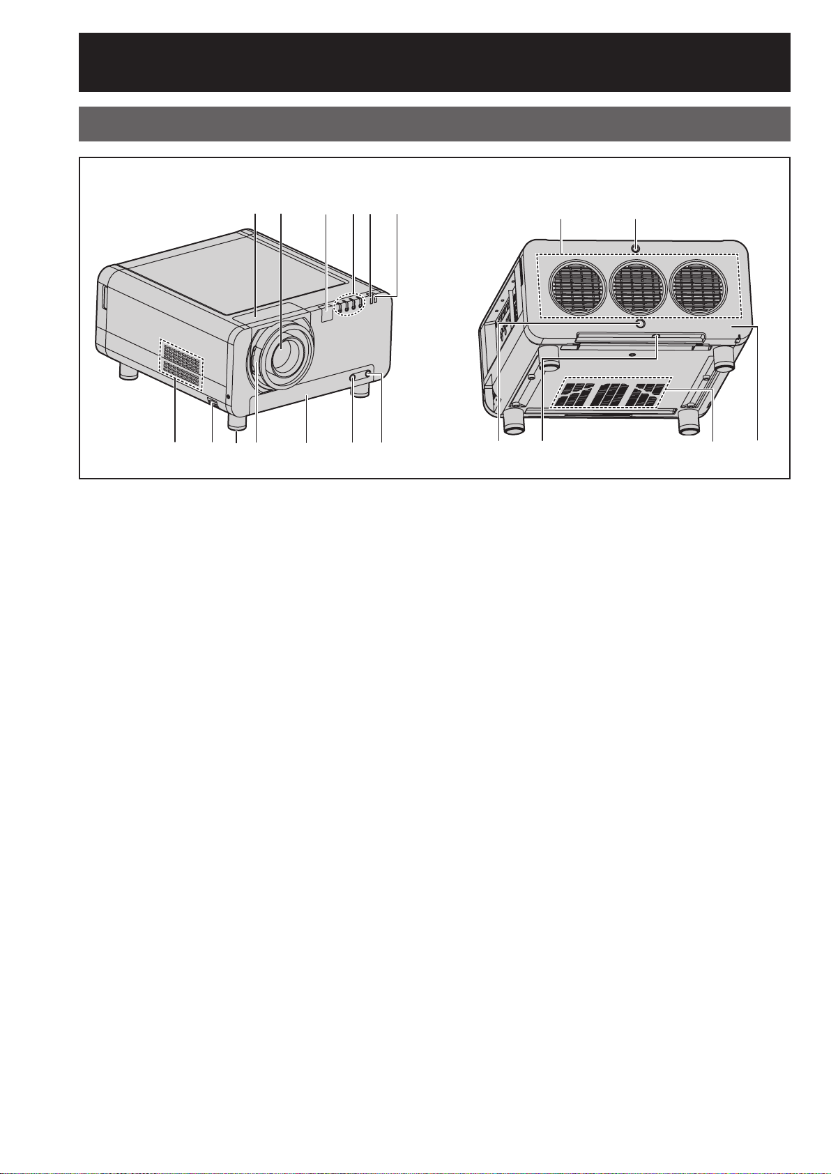
Projector Main Unit
Front■
$%&()
#
*+-. / 01
# Projectin lens cover ................................... (p. 33)
$ Projection lens (optional)
Lens for projecting images on the screen.
% Remote control receiver window (front) ..(p. 17)
This window receives the signal beam emitted from
the remote control.
LAMP (LAMP1, LAMP2, LAMP3, LAMP4)
&
monitor ...................................................... (p. 107)
These light when it is time to replace the lamp unit.
It also blinks if something unusual occurs in the
lamp circuit.
( Temperature monitor (TEMP) .................. (
Lighting or blinking of this lamp indicates an
abnormal condition of the internal temperature.
) Power indicator lamp ................................. (p. 34)
The lamp lights in red when the MAIN POWER
switch is turned to “ l ” (on). It turns to green when
the POWER ON button of the remote control or the
main unit is pressed.
* Air exhaust vents
+ Burglar hook
Attach a commercial burglar prevention cable to
this hook port.
- Adjustable feet ............................................ (p. 20)
Use these feet to adjust the tilt of the projector.
(Adjustable feet are provided at the front and rear,
right and left.)
p. 107)
Rear■
2*
3645
. Projection lens cover lock button ............. (p. 33)
This button toggles between lock and unlock of the
detachable cover for the projection lens (optional).
/ Air filter ...................................................... (p. 108)
0 Air filter cleaning monitor ...........(pp. 80-81, 108)
This blinks blue while the air filter is being cleaned.
It lights red when there is a problem with the air
filter.
1 Air filter unit screw ................................... (
This is used to secure the air filter cover.
2 Lamp unit cover screw ............................(
This is used to secure the lamp unit cover.
3 Remote control receiver window (rear) .... (p. 17)
This also receives the signal beam coming from
the remote control.
4 Remote control receiver window (bottom)
..................................................................... (p. 17)
This also receives the signal beam coming from
the remote control.
5 Air intake vents
Do not cover this vents.
6 Lamp unit cover ........................................ (p. 111)
The lamp unit is housed.
p. 108)
p. 111)
14 – ENGLISH
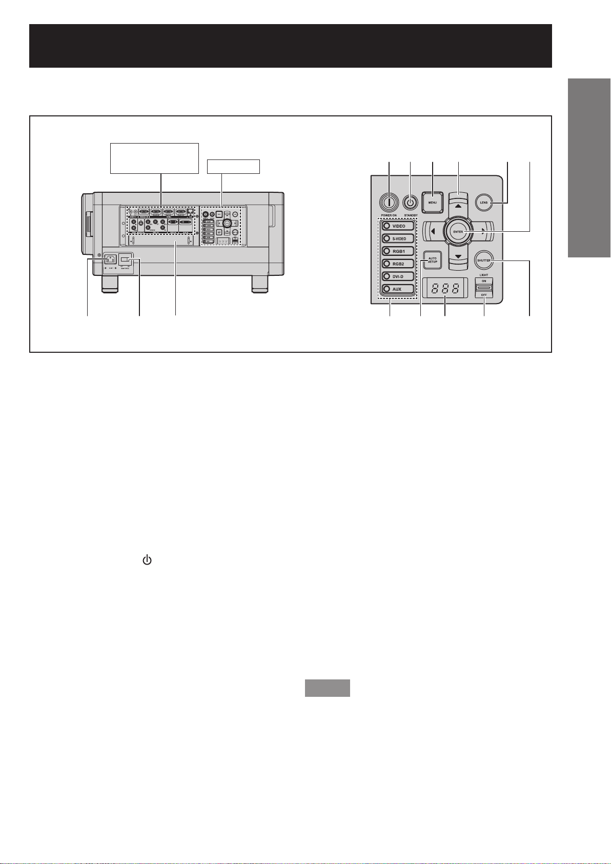
Controls■Side■
Connection
terminals (p. 16)
#$% 12
# AC IN terminal ............................................. (p. 34)
Connect the supplied line power cord into this
receptacle.
Do not connect any other cable to this socket.
$ MAIN POWER switch .........................(pp. 35, 36)
Use this switch to turn on “I” and off “○” the
commercial line power applied to the projector.
% Slot cover .................................................... (p. 28)
Install the input module here.
& POWER ON ( I ) button .......................(
When the projector is in standby mode with the
MAIN POWER switch of the projector at the “ l ”
side, this button switches the projector to projection
mode.
(
POWER STANDBY ( ) button..........(pp. 34, 36)
When the projector is in projection mode with the
MAIN POWER switch of the projector at the “ l ”
side, this button switches the projector to standby
mode.
) MENU button ....................................... (pp. 46, 48)
Displays and clears the Main Menu. It can also
return to the previous screen when the menu is
displayed.
Menus can be displayed by holding down the
MENU button for at least 3 seconds while the
on-screen indication function is OFF.
* Arrow ▲▼◄► buttons ......................(pp. 48, 99)
Use to select an item on the menu screen, change
setting and adjust the level.
Also use them to enter the “SECURITY” password.
Controls
pp. 34, 35)
&() * + -
./0
+ LENS button ................................................ (p. 37)
Switches to the adjustment mode for lens focus,
zoom and shift (position).
- ENTER button ............................................. (p. 48)
Press this button to enter your menu selection or to
run function.
. Input select (VIDEO, S-VIDEO, RGB1, RGB2,
DVI-D, AUX) button ..................................... (p. 43)
Use to change the VIDEO, S-VIDEO, RGB1,
RGB2, DVI-D and AUX (module input) input ports.
/ AUTO SETUP button .................................. (
Pressing this button while projecting an image
automatically corrects the picture positioning on
the screen. While the auto setup feature is active,
a message “EXECUTING...” appears on the
screen.
0 Self-diagnosis display .................... (
1 LIGHT ON/OFF button
This switch is used for illuminating the connection
terminals and controls.
2 SHUTTER button ........................................ (p. 43)
Press this button to black out the image
temporarily.
pp. 114-115)
p. 44)
Note
The AUX button to switch the input is disabled when
•
an optional input module is not connected.
Getting Started
ENGLISH – 15
Location and function of each part (continued)
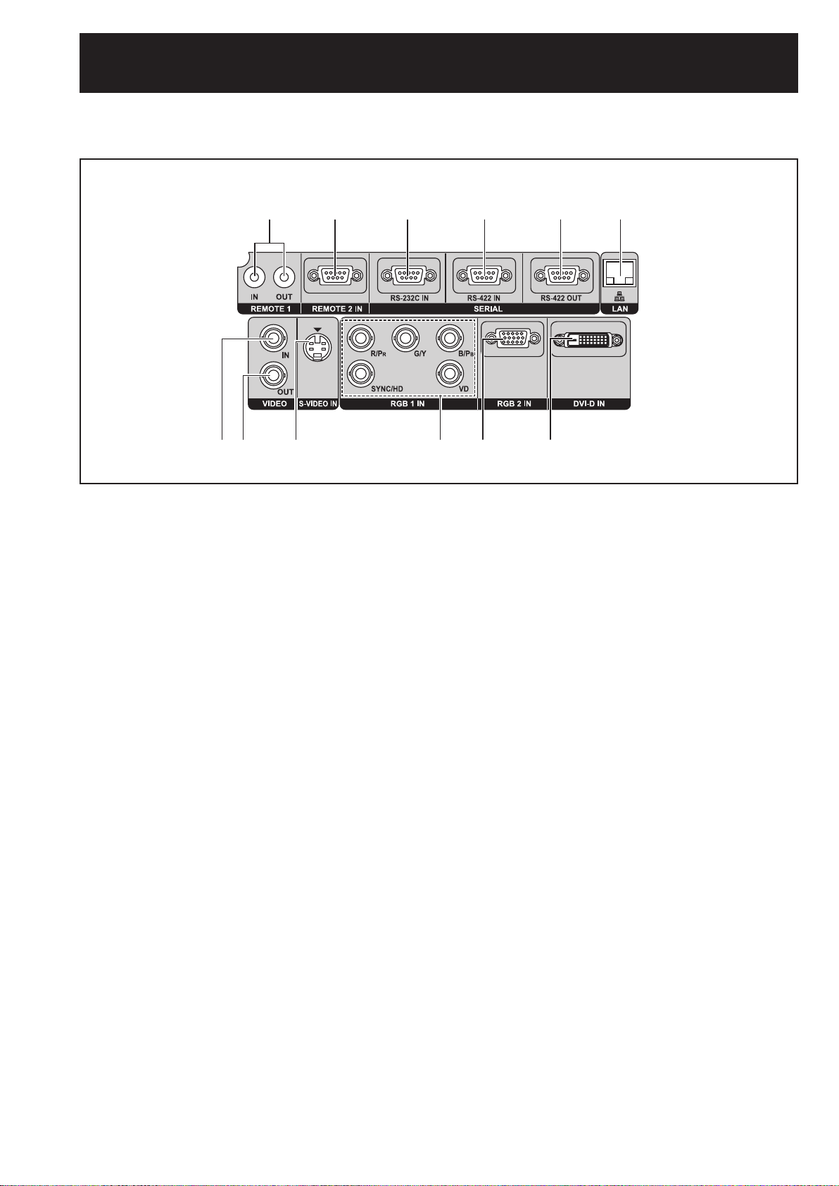
Connection terminals■
#$ % & ()
*+ - . / 0
# REMOTE1 lN/OUT terminal ........................(p. 18)
When two or more main units are used in the
system, they can be connected and controlled with
a wired remote control cable (M3 jack).
$ REMOTE2 IN terminal ..............................(
The user can remotely control the main unit by
using an external control circuit to this terminal
(D-SUB 9-pin female).
% SERIAL IN terminal .......(pp. 25, 26, 79, 102-105)
This terminal is an RS-232C compliant input
terminal (switching necessary) to connect a PC
and to externally control the main unit (D-SUB
9-pin female).
& SERIAL IN terminal .......(pp. 25, 26, 79, 102-105)
This terminal is an RS-422 compliant input terminal
(switching necessary) to connect a PC and to
externally control the main unit (D-SUB 9-pin
female).
( SERIAL OUT terminal ............... (pp. 26, 102-105)
This terminal is an RS-422 compliant output
terminal (switching necessary) to supply signals
given to the serial input terminal (D-SUB 9-pin
male).
p. 106)
LAN terminal (10BASE-T/100BASE-TX)
)
...................................................... (pp. 25, 26, 85)
This terminal is used for connecting a LAN cable.
* VIDEO IN terminal .......................................(
An input terminal for video signals. (BNC)
+ VIDEO OUT terminal ...................................(p. 25)
An output terminal (active through) for video
signals. (BNC)
- S-VIDEO IN terminal ...................................(
An input terminal for S-video signals (Mini DIN
4-pin). This terminal complies with S1 signals
and automatically toggles between 16:9 and 4:3
according to the size of input signals.
. RGB (YP
A terminal to input RGB or YPBPR signals (BNC).
/ RGB2 IN terminal ........................................(p. 26)
A terminal to input RGB or YPBPR signals (D-SUB
15-pin female).
0 DVI-D IN terminal ............................... (pp. 25, 26)
An input terminal for DVI-D signals.
BPR) 1 IN terminal ................ (pp. 25, 26)
p. 25)
p. 25)
16 – ENGLISH
Using the remote control unit
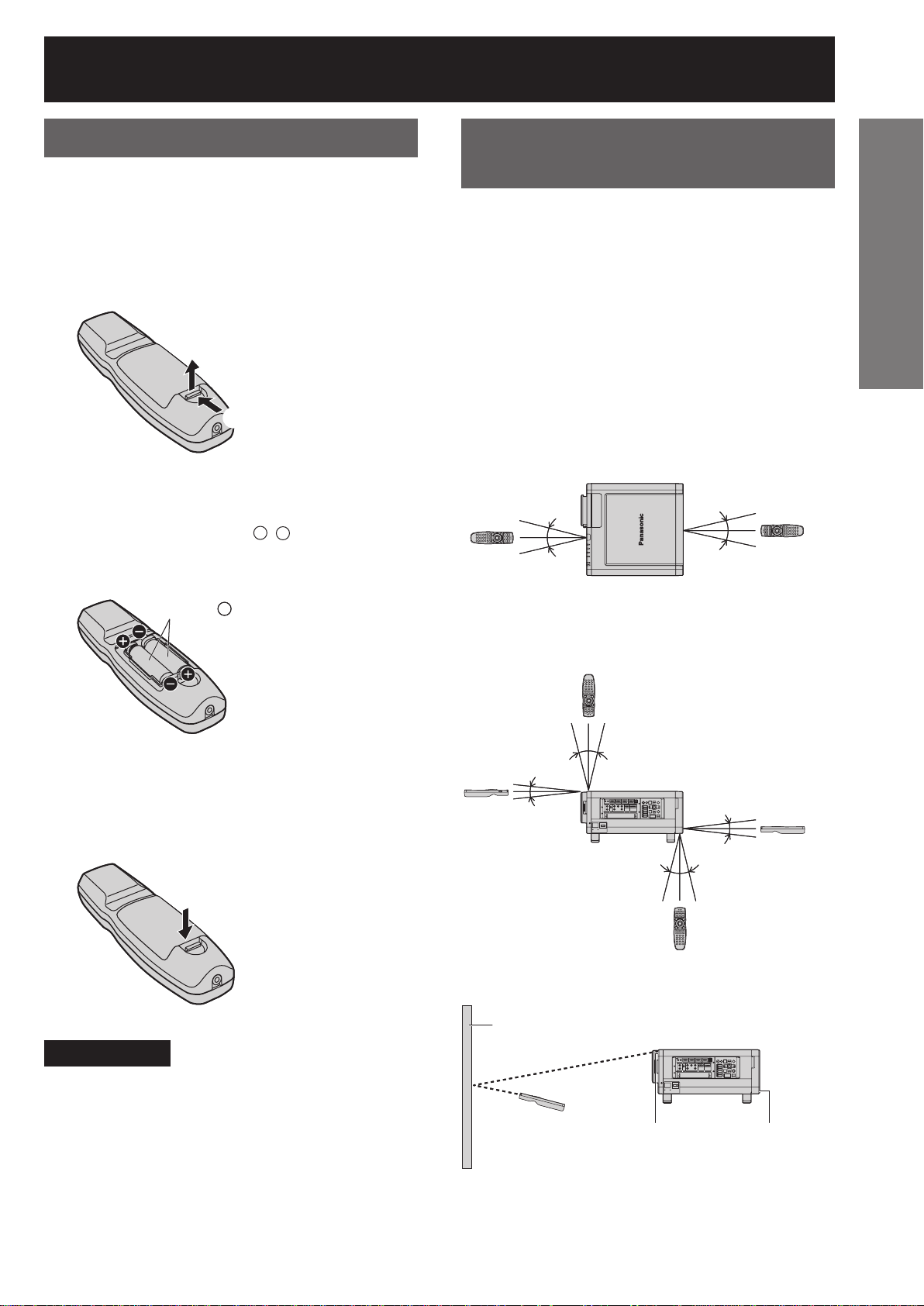
Loading batteries
When loading supplied AA batteries into the battery
compartment of the Remote Control, make sure that
their polarities are correct.
1. Open battery compartment lid.
•
Open the lid in the order # and then $.
$#$
#
2. Insert the batteries.
•
Into battery compartment, with their polarities
orientated as indicated (+, –) in the
compartment.
Supplied AA batteries
Supplied AA batteries
(insert the – side first).
(insert the – side first).
Effective range of remote
control operation
The Remote Control should normally be aimed at
either the front or rear remote control receiver window
on the projector (figure 1).
The effective control range is approx. 30 metres from
the beam receiver on the front or rear.
Otherwise, it may also be aimed at the screen, which
will reflect commands back to the projector’s front
receiver window as illustrated in figure 2.
When the Remote Control is aimed at the screen,
•
the effective control range may be reduced due to
the optical loss by screen reflection.
Figure 1
• Top View
(Front) (Rear)
(Front) (Rear)
30°
30°
30°
30°
Remote
Remote
Control
Control
Remote
Remote
Control
Control
30°
30°
30°
30°
Getting Started
3. Close the battery compartment
lid.
Replace the battery compartment lid over the
•
compartment and slide until it clicks.
Attention
Do not drop the Remote Control unit.
•
Do not expose Remote Control unit to any liquid.
•
Do not use NiCd batteries.
•
Release the LOCK button before operating the
•
remote control. (p. 13)
• Side View
15°
15°
15°
Remote
Remote
Control
Control
Figure 2
15°
Screen
Screen
Remote
Remote
Control
Control
Remote
Remote
Control
Control
30° 30°
30° 30°
Remote Control
Remote Control
receiver window
receiver window
(front)
(front)
30° 30°
30° 30°
Remote
Remote
Control
Control
Projector
Projector
15°
15°
15°
15°
Remote
Remote
Control
Control
Remote Control
Remote Control
receiver window
receiver window
(rear)
(rear)
ENGLISH – 17
Using the remote control unit (continued)
Note
The Remote Control may not function properly if an
•
object is in the light path.
The Remote Control receiver may not function
•
properly in intense ambient light such as fluorescent
lamps. Carefully site the projector so its Remote
Control receiver windows will not be directly
exposed to intense light.
Setting projector ID
number to remote control
Every projector has its ID number and the ID number
of the controlling projector must be set to the remote
control in advance so that the user can operate
the remote control. (p. 75) The ID number of the
projector is set to “ALL” on shipping, and use the
ID ALL button of the remote control when using
only a single projector.
1. Press ID SET, and then within
5 seconds, press the two
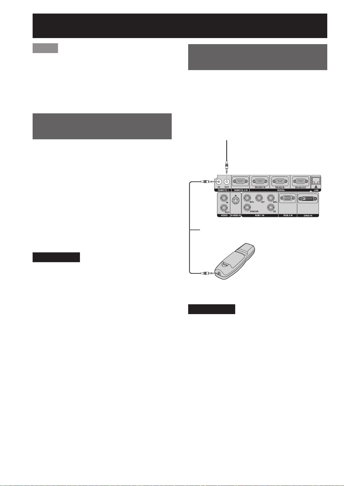
Using a wired remote
control
When multiple main units are connected as part of
the system, connect to units with a M3 stereo mini
jack cable (sold separately) to simultaneously control
multiple main units with a single remote control
through the REMOTE1 IN/OUT terminal. It is effective
to use the wired remote control in the environment in
which an obstacle stands in the light path or where
devices are susceptible to outside light.
Connect to the secondary projector
Connect to the secondary projector
Connection terminals
Connection terminals
numeric (0-9) buttons which
correspond to the ID number that
has been set for the projector.
Attention
Do not press the ID SET button accidentally or
•
carelessly because the ID number on the Remote
Control can be set even when no projector is
around.
If you do not enter the two-digit ID number within
•
5 seconds after the ID SET button has been
pressed, the ID number will remain at the number
that was set before the ID SET button was pressed.
Your specified ID number is stored in the remote
•
control unit unless another one is specified later.
However, the stored ID will be erased if the batteries
of the remote control are left exhausted. When the
batteries are replaced, set the same ID number
again.
M3 stereo mini pin-PIN cable
M3 stereo mini pin-PIN cable
(sold separately)
(sold separately)
Remote Control
Remote Control
Attention
Use a two-wire shielded cable with a length of 15 m
•
or less. If the length of the cable exceeds 15 m, the
shielding of the cable may not be sufficient and the
remote control may not work.
18 – ENGLISH
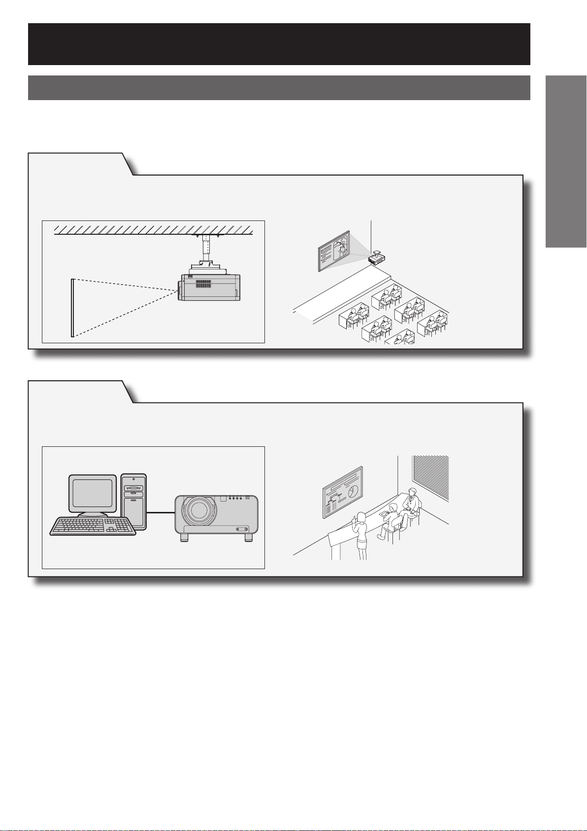
Installation
Examples of system expansion
The projector is provided with a number of terminals and optional accessories to enable various system
expansions. Both input and output are provided to all terminals on the main unit.
The following are some examples of system expansion:
System 1
The optional high- or low-ceiling mount bracket flexibly fits the projector in
individual site conditions.
Getting Started
System 2
Connection to a computer via the DVI-D IN terminal or DVI-D input module
(optional).
ENGLISH – 19
Installation (continued)
Adjusting the feet
The four adjustable feet mounted at the bottom of the projector are level-adjustable (0 mm–15 mm) which can be
used when the floor surface is not horizontal.
(Front) (Rear)(Front) (Rear)
Projection scheme
This projector can use any of the four projection schemes. Select the most suitable scheme to the situation of your
location. Use the OPTION menu on the menu screen to choose the desired projection scheme. (p. 76)
Floor Ceiling
Floor Ceiling
Front
Front
Rear
Rear
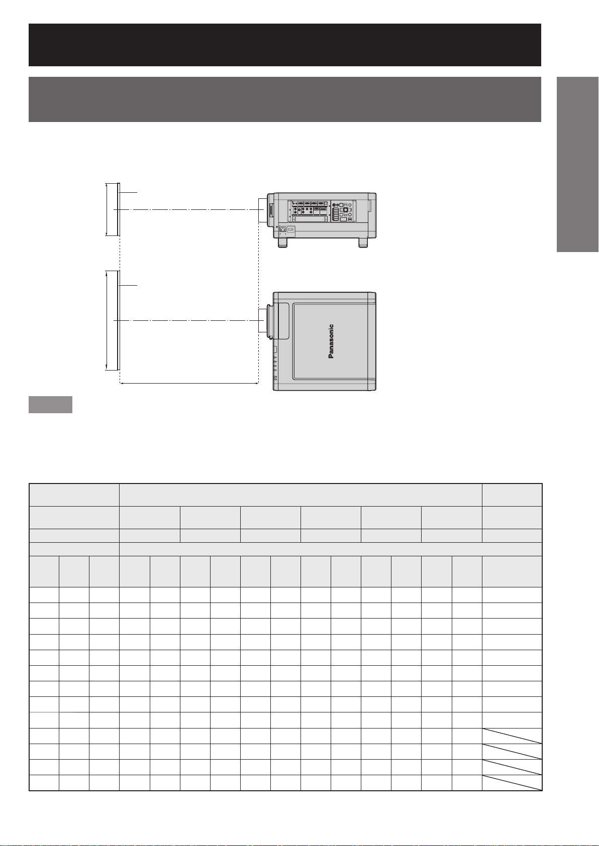
Installation geometry
When planning the projector and screen geometry, refer to the figures below and the information on the next page
for reference. After the projector is roughly positioned, picture size and vertical picture positioning can be finely
adjusted with the powered zoom lens and lens shifting mechanism.
When attaching an optional ceiling
●
When attaching an optional ceiling
●
mount bracket (ET-PKD100H)
mount bracket (ET-PKD100H)
Side View (unit : mm/inch)
Side View (unit : mm/inch)
580.5 - 700.5
580.5 - 700.5
(22.9˝ - 27.6˝)
H
H
SH
SH
H
H
Screen
Screen
L: Projection distance SW: Image width
L: Projection distance SW: Image width
SH: Height of the image H:
SH: Height of the image H:
* For PT-D10000U: H = 0
* For PT-D10000U: H = 0
For PT-DW10000U: H = -0.1 × SH
For PT-DW10000U: H = -0.1 × SH
* However, if the ET-D75LE5 has been installed, the value
* However, if the ET-D75LE5 has been installed, the value
will be fixed at H=SH/2 for both the PT-D10000U and
will be fixed at H=SH/2 for both the PT-D10000U and
PT-DW10000U. If the ET-D75LE6 has been installed,
PT-DW10000U. If the ET-D75LE6 has been installed,
the values will be H = 0.1 × SH to 0.9 × SH for the
the values will be H = 0.1 × SH to 0.9 × SH for the
PT-D10000U, and H = 0 to SH for the PT-DW10000U.
PT-D10000U, and H = 0 to SH for the PT-DW10000U.
L
L
L
L
254
254
(10˝)
(10˝)
Vertical distance between the
Vertical distance between the
lens Center level and the bottom
lens Center level and the bottom
edge of the projected image
edge of the projected image
to SH
to SH
to 1.1 × SH
to 1.1 × SH
(22.9˝ - 27.6˝)
Top View (unit : mm/inch)
Top View (unit : mm/inch)
L
SW
SW
Screen
Screen
ET-D75LE1 62.5 (2.5˝)
ET-D75LE1 62.5 (2.5˝)
ET-D75LE2 47 (1.9˝)
ET-D75LE2 47 (1.9˝)
ET-D75LE3 50.5 (2˝)
ET-D75LE3 50.5 (2˝)
ET-D75LE4 74.4 (2.9˝)
ET-D75LE4 74.4 (2.9˝)
ET-D75LE5 150.5 (5.9˝)
ET-D75LE5 150.5 (5.9˝)
ET-D75LE6 160 (6.3˝)
ET-D75LE6 160 (6.3˝)
ET-D75LE8 202.5 (8˝)
ET-D75LE8 202.5 (8˝)
L
Lens Dimension of L1 (Approx.)
Lens Dimension of L1 (Approx.)
200
200
(7.9˝)
(7.9˝)
L1
L1
254
254
(10˝)
(10˝)
175
175
(6.9˝)
(6.9˝)
66
66
(2.6˝)
(2.6˝)
120
120
(4.7˝)
(4.7˝)
314
314
(12.4˝)
(12.4˝)
20 – ENGLISH
Projection distances by the type of projection lenses
(optional)
Every type of optional projection lenses has a different projection distance to achieve the same screen size. Select
and purchase a projection lens most suitable to the size of your location referring to the following tables and the
projection distances by the type of projection lenses on the next page.
Side View
Side View
Screen
Screen
SH
SH
Top View
Top View
Screen
Screen
SW
SW
L : Projection distance
L : Projection distance
SH : Effective screen height
L
L
SH : Effective screen height
SW : Effective screen width
SW : Effective screen width
Getting Started
Note
•
The projection distances listed here involve an error of ±5 %.
•
Keystone distortions are corrected in the way the screen size becomes smaller than the original one.
Projection distances by the type of projection lenses (for PT-DW10000U)
■
For the screen aspect ratio of 16:9 (Units: m (feet/inches))
●
Lens type Zoom lens
Lens type Zoom lens
Model number of
Model number of
projection lens
projection lens
Throw ratio*
Throw ratio*
Screen dimensions Projection distance (L)
Screen dimensions Projection distance (L)
Screen
Screen
size
size
(inch)
(inch)
70
70
80
80
90
90
100
100
120
120
150
150
200
200
250
250
300
300
350
350
400
400
500
500
600
600
Effective
Effective
height
height
(SH)
(SH)
0.872
0.872
(2´10˝)
(2´10˝)
0.996
0.996
(3´3˝)
(3´3˝)
1.121
1.121
(3´8˝)
(3´8˝)
1.245
1.245
(4´1˝)
(4´1˝)
1.494
1.494
(4´10˝)
(4´10˝)
1.868
1.868
(6´1˝)
(6´1˝)
2.491
2.491
(8´2˝)
(8´2˝)
3.113
3.113
(10´2˝)
(10´2˝)
3.736
3.736
(12´3˝)
(12´3˝)
4.358
4.358
(14´3˝)
(14´3˝)
4.981
4.981
(16´4˝)
(16´4˝)
6.226
6.226
(20´5˝)
(20´5˝)
7.472
7.472
(24´6˝)
(24´6˝)
Effective
Effective
width
width
1.550
1.550
(5´1˝)
(5´1˝)
1.771
1.771
(5´9˝)
(5´9˝)
1.992
1.992
(6´6˝)
(6´6˝)
2.214
2.214
(7´3˝)
(7´3˝)
2.657
2.657
(8´8˝)
(8´8˝)
3.321
3.321
(10´10˝)
(10´10˝)
4.428
4.428
(14´6˝)
(14´6˝)
5.535
5.535
(18´1˝)
(18´1˝)
6.641
6.641
(21´9˝)
(21´9˝)
7.748
7.748
(25´5˝)
(25´5˝)
8.855
8.855
11.069
11.069
(36´3˝)
(36´3˝)
13.283
13.283
(43´6˝)
(43´6˝)
ET-D75LE1 ET-D75LE2 ET-D75LE3 ET-D75LE4 ET-D75LE8 ET-D75LE6 ET-D75LE5
ET-D75LE1 ET-D75LE2 ET-D75LE3 ET-D75LE4 ET-D75LE8 ET-D75LE6 ET-D75LE5
1
1
1.4-1.8 : 1 1.8-2.8 : 1 2.8-4.6 : 1 4.6-7.4 : 1 7.3-13.8 : 1 0.9-1.1 : 1 0.7 : 1
1.4-1.8 : 1 1.8-2.8 : 1 2.8-4.6 : 1 4.6-7.4 : 1 7.3-13.8 : 1 0.9-1.1 : 1 0.7 : 1
Min. Max. Min. Max. Min. Max. Min. Max. Min. Max. Min. Max. Fixed
Min. Max. Min. Max. Min. Max. Min. Max. Min. Max. Min. Max. Fixed
(SW)
(SW)
2.07
2.77
(29´)
(29´)
2.07
(6´9˝)
(6´9˝)
2.38
2.38
(7´9˝)
(7´9˝)
2.68
2.68
(8´9˝)
(8´9˝)
2.99
2.99
(9´9˝)
(9´9˝)
3.60
3.60
(11´9˝)
(11´9˝)
4.53
4.53
(14´10˝)
(14´10˝)
6.06
6.06
(19´10˝)
(19´10˝)
7.59
7.59
(24´10˝)
(24´10˝)
9.13
9.13
(29´11˝)
(29´11˝)
10.66
10.66
(34´11˝)
(34´11˝)
12.19
12.19
(39´11˝)
(39´11˝)
15.26
15.26
(50´)
(50´)
18.33
18.33
(60´1˝)
(60´1˝)
2.77
(9´1˝)
(9´1˝)
3.18
3.18
(10´5˝)
(10´5˝)
3.59
3.59
(11´9˝)
(11´9˝)
4.00
4.00
(13´1˝)
(13´1˝)
4.82
4.82
(15´9˝)
(15´9˝)
6.05
6.05
(19´10˝)
(19´10˝)
8.10
8.10
(26´6˝)
(26´6˝)
10.15
10.15
(33´3˝)
(33´3˝)
12.19
12.19
(39´11˝)
(39´11˝)
14.24
14.24
(46´8˝)
(46´8˝)
16.29
16.29
(53´5˝)
(53´5˝)
20.39
20.39
(66´10˝)
(66´10˝)
24.49
24.49
(80´4˝)
(80´4˝)
2.80
2.80
(9´2˝)
(9´2˝)
3.21
3.21
(10´6˝)
(10´6˝)
3.62
3.62
(11´10˝)
(11´10˝)
4.04
4.04
(13´3˝)
(13´3˝)
4.86
4.86
(15´11˝)
(15´11˝)
6.09
6.09
(19´11˝)
(19´11˝)
8.15
8.15
(26´8˝)
(26´8˝)
10.21
10.21
(33´5˝)
(33´5˝)
12.27
12.27
(40´3˝)
(40´3˝)
14.32
14.32
(46´11˝)
(46´11˝)
16.38
16.38
(53´8˝)
(53´8˝)
20.50
20.50
(67´3˝)
(67´3˝)
24.61
24.61
(80´8˝)
(80´8˝)
4.21
4.21
(13´9˝)
(13´9˝)
4.83
4.83
(15´10˝)
(15´10˝)
5.45
5.45
(17´10˝)
(17´10˝)
6.07
6.07
(19´10˝)
(19´10˝)
7.30
7.30
(23´11˝)
(23´11˝)
9.15
9.15
(30´)
(30´)
12.24
12.24
(40´1˝)
(40´1˝)
15.33
15.33
(50´3˝)
(50´3˝)
18.41
18.41
(60´4˝)
(60´4˝)
21.50
21.50
(70´6˝)
(70´6˝)
24.58
24.58
(80´7˝)
(80´7˝)
30.76
30.76
(100´11˝)
(100´11˝)
36.93
36.93
(121´1˝)
(121´1˝)
4.23
4.23
(13´10˝)
(13´10˝)
4.84
4.84
(15´10˝)
(15´10˝)
5.46
5.46
(17´10˝)
(17´10˝)
6.08
6.08
(19´11˝
(19´11˝
7.31
7.31
(23´11˝)
(23´11˝)
9.16
9.16
(30´)
(30´)
12.25
12.25
(40´2˝)
(40´2˝)
15.34
15.34
(50´3˝)
(50´3˝)
18.42
18.42
(60´5˝)
(60´5˝)
21.51
21.51
(70´6˝)
(70´6˝)
24.60
24.60
(80´8˝)
(80´8˝)
30.77
30.77
(100´11˝)
(100´11˝)
36.94
36.94
(121´2˝)
(121´2˝)
7.09
7.09
(23´3˝)
(23´3˝)
8.13
8.13
(26´8˝)
(26´8˝)
9.16
9.16
(30´)
(30´)
10.19
10.19
)
(33´5˝)
)
(33´5˝)
12.25
12.25
(40´2˝)
(40´2˝)
15.34
15.34
(50´3˝)
(50´3˝)
20.50
20.50
(67´3˝)
(67´3˝)
25.65
25.65
(84´1˝)
(84´1˝)
30.81
30.81
(101´)
(101´)
35.96
35.96
(117´11˝)
(117´11˝)
41.12
41.12
(134´10˝)
(134´10˝)
51.42
51.42
(168´8˝)
(168´8˝)
61.73
61.73
(202´6˝)
(202´6˝)
7.10
7.10
(23´3˝)
(23´3˝)
8.13
8.13
(26´8˝)
(26´8˝)
9.16
9.16
(30´)
(30´)
10.19
10.19
(33´5˝)
(33´5˝)
12.26
12.26
(40´2˝)
(40´2˝)
15.35
15.35
(50´4˝)
(50´4˝)
20.50
20.50
(67´3˝)
(67´3˝)
25.66
25.66
(84´2˝)
(84´2˝)
30.81
30.81
(101´)
(101´)
35.97
35.97
(118´)
(118´)
41.12
41.12
(134´10˝)
(134´10˝)
51.43
51.43
(168´8˝)
(168´8˝)
61.74
61.74
(202´6˝)
(202´6˝)
11.37
11.37
(37´3˝)
(37´3˝)
13.01
13.01
(42´8˝)
(42´8˝)
14.65
14.65
(48´)
(48´)
16.29
16.29
(53´5˝)
(53´5˝)
19.57
19.57
(64´2˝)
(64´2˝)
24.49
24.49
(80´4˝)
(80´4˝)
32.69
32.69
(107´3˝)
(107´3˝)
40.88
40.88
(134´1˝)
(134´1˝)
49.08
49.08
(161´)
(161´)
57.28
57.28
(187´11˝)
(187´11˝)
65.47
65.47
(214´9˝)
(214´9˝)
81.87
81.87
(268´7˝)
(268´7˝)
98.26
98.26
(322´4˝)
(322´4˝)
11.09
11.09
(36´4˝)
(36´4˝)
12.73
12.73
(41´9˝)
(41´9˝)
14.37
14.37
(47´1˝)
(47´1˝)
16.01
16.01
(52´6˝)
(52´6˝)
19.29
19.29
(63´3˝)
(63´3˝)
24.21
24.21
(79´5˝)
(79´5˝)
32.40
32.40
(106´3˝)
(106´3˝)
40.60
40.60
(133´2˝)
(133´2˝)
48.80
48.80
(160´1˝)
(160´1˝)
57.00
57.00
(187´)
(187´)
65.19
65.19
(213´10˝)
(213´10˝)
81.59
81.59
(267´8˝)
(267´8˝)
97.98
97.98
(321´5˝)
(321´5˝)
21.14
21.14
(69´4˝)
(69´4˝)
24.21
24.21
(79´5˝)
(79´5˝)
27.29
27.29
(89´6˝)
(89´6˝)
30.36
30.36
(99´7˝)
(99´7˝)
36.50
36.50
(119´9˝)
(119´9˝)
45.72
45.72
(150´)
(150´)
61.08
61.08
(200´4˝)
(200´4˝)
76.44
76.44
(250´9˝)
(250´9˝)
91.79
91.79
(301´1
(301´1
107.15
107.15
(351´6˝)
(351´6˝)
122.51
122.51
(401´11˝)
(401´11˝)
153.23
153.23
(502´8˝)
(502´8˝)
183.95
183.95
(603´6˝)
(603´6˝)
˝)
˝)
1.39
1.39
(4´6˝)
(4´6˝)
1.60
1.60
(5´2˝)
(5´2˝)
1.81
1.81
(5´11˝)
(5´11˝)
2.01
2.01
(6´7˝)
(6´7˝)
2.43
2.43
(7´11˝)
(7´11˝)
3.05
3.05
(10´)
(10´)
4.08
4.08
(13´4˝)
(13´4˝)
5.12
5.12
(16´9˝)
(16´9˝)
6.15
6.15
(20´2˝)
(20´2˝)
7.19
7.19
(23´7˝)
(23´7˝)
8.22
8.22
(26´11˝)
(26´11˝)
10.29
10.29
(33´9˝)
(33´9˝)
12.36
12.36
(40´6˝)
(40´6˝)
1.66
1.66
(5´5˝)
(5´5˝)
1.91
1.91
(6´3˝)
(6´3˝)
2.16
2.16
(7´1˝)
(7´1˝)
2.41
2.41
(7´10˝)
(7´10˝)
2.90
2.90
(9´6˝)
(9´6˝)
3.65
3.65
(11´11˝)
(11´11˝)
4.89
4.89
(16´)
(16´)
6.13
6.13
(20´1˝)
(20´1˝)
7.37
7.37
(24´2˝)
(24´2˝)
8.61
8.61
(28´2˝)
(28´2˝)
9.85
9.85
(32´3˝)
(32´3˝)
12.33
12.33
(40´5˝)
(40´5˝)
14.81
14.81
(48´7˝)
(48´7˝)
Fixed-focus
Fixed-focus
lens
lens
1.02 (3´4˝)
1.02 (3´4˝)
1.18 (3´10˝)
1.18 (3´10˝)
1.34 (4´4˝)
1.34 (4´4˝)
1.50 (4´11˝)
1.50 (4´11˝)
1.81 (5´11˝)
1.81 (5´11˝)
2.29 (7´6˝)
2.29 (7´6˝)
3.08 (10´1˝)
3.08 (10´1˝)
3.87 (12´8˝)
3.87 (12´8˝)
4.66 (15´3˝)
4.66 (15´3˝)
*1: “Throw ratio” is the approximate measurement range of the screen width to the projection distance.
ENGLISH – 21
Installation (continued)
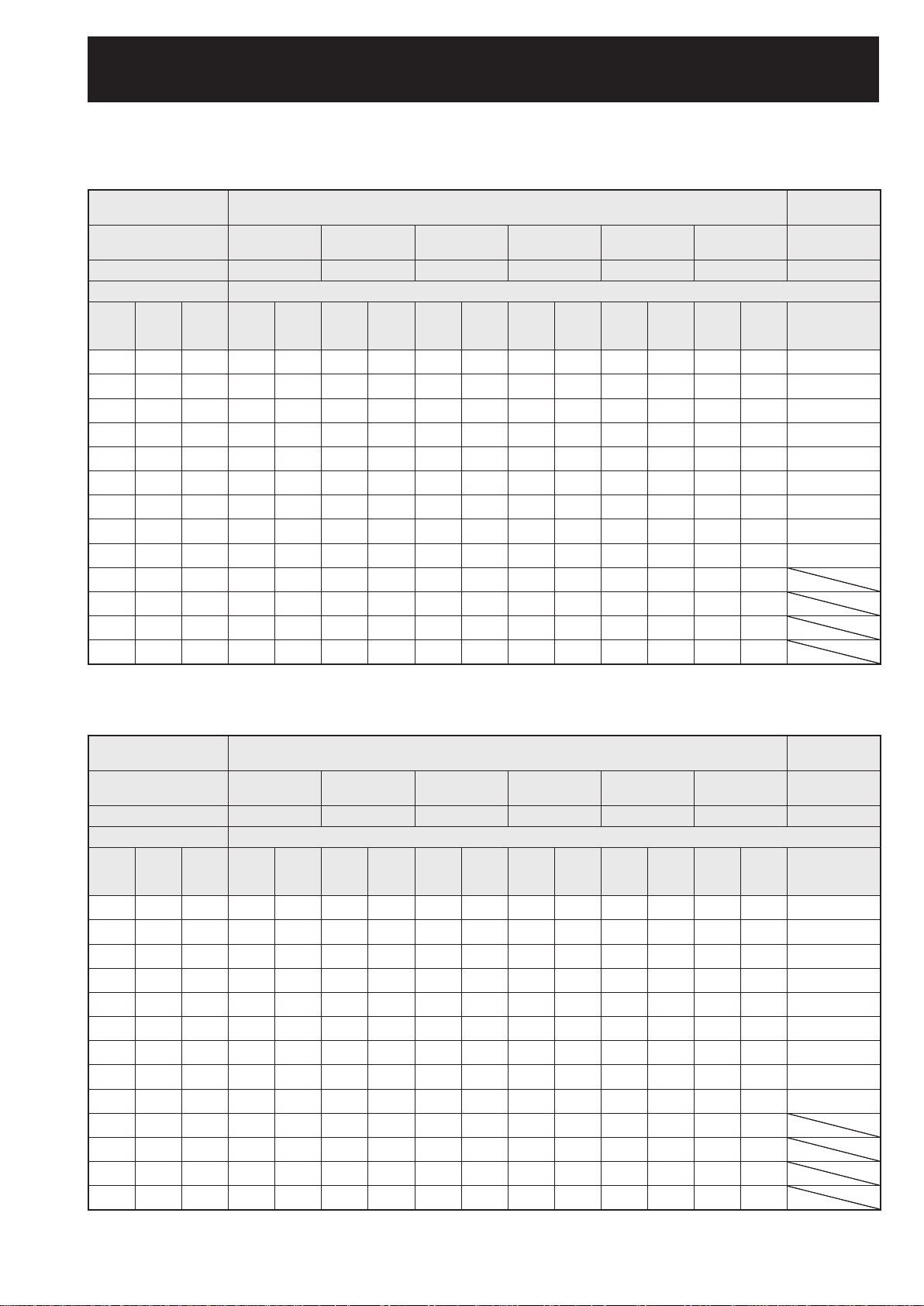
Projection distances by the type of projection lenses (for PT-D10000U)
■
For the screen aspect ratio of 4:3 (Units: m (feet/inches))
●
Lens type Zoom lens
Lens type Zoom lens
Model number of
Model number of
projection lens
projection lens
Throw ratio*
Throw ratio*
Screen dimensions Projection distance (L)
Screen dimensions Projection distance (L)
Screen
Effective
Effective
height
height
(SH)
(SH)
1.067
1.067
(3´6˝)
(3´6˝)
1.219
1.219
(3´11˝)
(3´11˝)
1.372
1.372
(4´6˝)
(4´6˝)
1.524
1.524
(5´)
(5´)
1.829
1.829
(6´)
(6´)
2.286
2.286
(7´6˝)
(7´6˝)
3.048
3.048
(10´)
(10´)
3.810
3.810
(12´6˝)
(12´6˝)
4.572
4.572
(15´)
(15´)
5.334
5.334
(17´6˝)
(17´6˝)
6.096
6.096
(20´)
(20´)
7.620
7.620
(25´)
(25´)
9.144
9.144
(30´)
(30´)
Effective
Effective
width
width
1.422
1.422
(4´7˝)
(4´7˝)
1.626
1.626
(5´4˝)
(5´4˝)
1.829
1.829
2.032
2.032
(6´8˝)
(6´8˝)
2.438
2.438
(7´11˝)
(7´11˝)
3.048
3.048
4.064
4.064
(13´4˝)
(13´4˝)
5.080
5.080
(16´8˝)
(16´8˝)
6.096
6.096
7.112
7.112
(23´4˝)
(23´4˝)
8.128
8.128
(26´8˝)
(26´8˝)
10.160
10.160
(33´4˝)
(33´4˝)
12.192
12.192
Screen
size
size
(inch)
(inch)
70
70
80
80
90
90
100
100
120
120
150
150
200
200
250
250
300
300
350
350
400
400
500
500
600
600
ET-D75LE1 ET-D75LE2 ET-D75LE3 ET-D75LE4 ET-D75LE8 ET-D75LE6 ET-D75LE5
ET-D75LE1 ET-D75LE2 ET-D75LE3 ET-D75LE4 ET-D75LE8 ET-D75LE6 ET-D75LE5
1
1
1.5-2.0 : 1 2.0-3.0 : 1 3.0-5.0 : 1 5.0-8.0 : 1 7.9-15.0 : 1 1.0-1.2 : 1 0.8 : 1
1.5-2.0 : 1 2.0-3.0 : 1 3.0-5.0 : 1 5.0-8.0 : 1 7.9-15.0 : 1 1.0-1.2 : 1 0.8 : 1
Min. Max. Min. Max. Min. Max. Min. Max. Min. Max. Min. Max. Fixed
Min. Max. Min. Max. Min. Max. Min. Max. Min. Max. Min. Max. Fixed
(SW)
(SW)
2.07
(6´)
(6´)
(10´)
(10´)
(20´)
(20´)
(40´)
(40´)
2.07
(6´9˝)
(6´9˝)
2.38
2.38
(7´9˝)
(7´9˝)
2.68
2.68
(8´9˝)
(8´9˝)
2.99
2.99
(9´9˝)
(9´9˝)
3.60
3.60
(11´9˝)
(11´9˝)
4.53
4.53
(14´10˝)
(14´10˝)
6.06
6.06
(19´10˝)
(19´10˝)
7.59
7.59
(24´10˝)
(24´10˝)
9.13
9.13
(29´11˝)
(29´11˝)
10.66
10.66
(34´11˝)
(34´11˝)
12.19
12.19
(39´11˝)
(39´11˝)
15.26
15.26
(50´)
(50´)
18.33
18.33
(60´1˝)
(60´1˝)
2.77
2.77
(9´1˝)
(9´1˝)
3.18
3.18
(10´5˝)
(10´5˝)
3.59
3.59
(11´9˝)
(11´9˝)
4.00
4.00
(13´1˝)
(13´1˝)
4.82
4.82
(15´9˝)
(15´9˝)
6.05
6.05
(19´10˝)
(19´10˝)
8.10
8.10
(26´6˝)
(26´6˝)
10.15
10.15
(33´3˝)
(33´3˝)
12.19
12.19
(39´11˝)
(39´11˝)
14.24
14.24
(46´8˝)
(46´8˝)
16.29
16.29
(53´5˝)
(53´5˝)
20.39
20.39
(66´10˝)
(66´10˝)
24.49
24.49
(80´4˝)
(80´4˝)
2.80
2.80
(9´2˝)
(9´2˝)
3.21
3.21
(10´6˝)
(10´6˝)
3.62
3.62
(11´10˝)
(11´10˝)
4.04
4.04
(13´3˝)
(13´3˝)
4.86
4.86
(15´11˝)
(15´11˝)
6.09
6.09
(19´11˝)
(19´11˝)
8.15
8.15
(26´8˝)
(26´8˝)
10.21
10.21
(33´5˝)
(33´5˝)
12.27
12.27
(40´3˝)
(40´3˝)
14.32
14.32
(46´11˝)
(46´11˝)
16.38
16.38
(53´8˝)
(53´8˝)
20.50
20.50
(67´3˝)
(67´3˝)
24.61
24.61
(80´8˝)
(80´8˝)
4.21
4.21
(13´9˝)
(13´9˝)
4.83
4.83
(15´10˝)
(15´10˝)
5.45
5.45
(17´10˝)
(17´10˝)
6.07
6.07
(19´10˝)
(19´10˝)
7.30
7.30
(23´11˝)
(23´11˝)
9.15
9.15
(30´)
(30´)
12.24
12.24
(40´1˝)
(40´1˝)
15.33
15.33
(50´3˝)
(50´3˝)
18.41
18.41
(60´4˝)
(60´4˝)
21.50
21.50
(70´6˝)
(70´6˝)
24.58
24.58
(80´7˝)
(80´7˝)
30.76
30.76
(100´11˝)
(100´11˝)
36.93
36.93
(121´1˝)
(121´1˝)
4.23
4.23
(13´10˝)
(13´10˝)
4.84
4.84
(15´10˝)
(15´10˝)
5.46
5.46
(17´10˝)
(17´10˝)
6.08
6.08
(19´11˝)
(19´11˝)
7.31
7.31
(23´11˝)
(23´11˝)
9.16
9.16
(30´)
(30´)
12.25
12.25
(40´2˝)
(40´2˝)
15.34
15.34
(50´3˝)
(50´3˝)
18.42
18.42
(60´5˝)
(60´5˝)
21.51
21.51
(70´6˝)
(70´6˝)
24.60
24.60
(80´8˝)
(80´8˝)
30.77
30.77
(100´11˝)
(100´11˝)
36.94
36.94
(121´2˝)
(121´2˝)
7.09
7.09
(23´3˝)
(23´3˝)
8.13
8.13
(26´8˝)
(26´8˝)
9.16
9.16
(30´)
(30´)
10.19
10.19
(33´5˝
(33´5˝
12.25
12.25
(40´2˝)
(40´2˝)
15.34
15.34
(50´3˝)
(50´3˝)
20.50
20.50
(67´3˝)
(67´3˝)
25.65
25.65
(84´1˝)
(84´1˝)
30.81
30.81
(101´)
(101´)
35.96
35.96
(117´11˝)
(117´11˝)
41.12
41.12
(134´10˝)
(134´10˝)
51.42
51.42
(168´8˝)
(168´8˝)
61.73
61.73
(202´6˝)
(202´6˝)
(23´3˝)
(23´3˝)
(26´8˝)
(26´8˝)
10.19
10.19
)
(33´5˝)
)
(33´5˝)
12.26
12.26
(40´2˝)
(40´2˝)
15.35
15.35
(50´4˝)
(50´4˝)
20.50
20.50
(67´3˝)
(67´3˝)
25.66
25.66
(84´2˝)
(84´2˝)
30.81
30.81
(101´)
(101´)
35.97
35.97
(118´)
(118´)
41.12
41.12
(134´10˝)
(134´10˝)
51.43
51.43
(168´8˝)
(168´8˝)
61.74
61.74
(202´6˝)
(202´6˝)
7.10
7.10
8.13
8.13
9.16
9.16
(30´)
(30´)
11.37
11.37
(37´3˝)
(37´3˝)
13.01
13.01
(42´8˝)
(42´8˝)
14.65
14.65
(48´)
(48´)
16.29
16.29
(53´5˝)
(53´5˝)
19.57
19.57
(64´2˝)
(64´2˝)
24.49
24.49
(80´4˝)
(80´4˝)
32.69
32.69
(107´3˝)
(107´3˝)
40.88
40.88
(134´1˝)
(134´1˝)
49.08
49.08
(161´)
(161´)
57.28
57.28
(187´11˝)
(187´11˝)
65.47
65.47
(214´9˝)
(214´9˝)
81.87
81.87
(268´7˝)
(268´7˝)
98.26
98.26
(322´4˝)
(322´4˝)
11.09
11.09
(36´4˝)
(36´4˝)
12.73
12.73
(41´9˝)
(41´9˝)
14.37
14.37
(47´1˝)
(47´1˝)
16.01
16.01
(52´6˝)
(52´6˝)
19.29
19.29
(63´3˝)
(63´3˝)
24.21
24.21
(79´5˝)
(79´5˝)
32.40
32.40
(106´3˝)
(106´3˝)
40.60
40.60
(133´2˝)
(133´2˝)
48.80
48.80
(160´1˝)
(160´1˝)
57.00
57.00
(187´)
(187´)
65.19
65.19
(213´10˝)
(213´10˝)
81.59
81.59
(267´8˝)
(267´8˝)
97.98
97.98
(321´5˝)
(321´5˝)
21.14
21.14
(69´4˝)
(69´4˝)
24.21
24.21
(79´5˝)
(79´5˝)
27.29
27.29
(89´6˝)
(89´6˝)
30.36
30.36
(99´7˝)
(99´7˝)
36.50
36.50
(119´9˝)
(119´9˝)
45.72
45.72
(150´)
(150´)
61.08
61.08
(200´4˝)
(200´4˝)
76.44
76.44
(250´9˝)
(250´9˝)
91.79
91.79
(301´1˝)
(301´1˝)
107.15
107.15
(351´6˝)
(351´6˝)
122.51
122.51
(401´11˝)
(401´11˝)
153.23
153.23
(502´8˝)
(502´8˝)
183.95
183.95
(603´6˝)
(603´6˝)
1.39
1.39
(4´6˝)
(4´6˝)
1.60
1.60
(5´2˝)
(5´2˝)
1.81
1.81
(5´11˝)
(5´11˝)
2.01
2.01
(6´7˝)
(6´7˝)
2.43
2.43
(7´11˝)
(7´11˝)
3.05
3.05
(10´)
(10´)
4.08
4.08
(13´4˝)
(13´4˝)
5.12
5.12
(16´9˝)
(16´9˝)
6.15
6.15
(20´2˝)
(20´2˝)
7.19
7.19
(23´7˝)
(23´7˝)
8.22
8.22
(26´11˝)
(26´11˝)
10.29
10.29
(33´9˝)
(33´9˝)
12.36
12.36
(40´6˝)
(40´6˝)
1.66
1.66
(5´5˝)
(5´5˝)
1.91
1.91
(6´3˝)
(6´3˝)
2.16
2.16
(7´1˝)
(7´1˝)
2.41
2.41
(7´10˝)
(7´10˝)
2.90
2.90
(9´6˝)
(9´6˝)
3.65
3.65
(11´11˝)
(11´11˝)
4.89
4.89
(16´)
(16´)
6.13
6.13
(20´1˝)
(20´1˝)
7.37
7.37
(24´2˝)
(24´2˝)
8.61
8.61
(28´2˝)
(28´2˝)
9.85
9.85
(32´3˝)
(32´3˝)
12.33
12.33
(40´5˝)
(40´5˝)
14.81
14.81
(48´7˝)
(48´7˝)
Fixed-focus
Fixed-focus
lens
lens
1.02 (3´4˝)
1.02 (3´4˝)
1.18 (3´10˝)
1.18 (3´10˝)
1.34 (4´4˝)
1.34 (4´4˝)
1.50 (4´11˝)
1.50 (4´11˝)
1.81 (5´11˝)
1.81 (5´11˝)
2.29 (7´6˝)
2.29 (7´6˝)
3.08 (10´1˝)
3.08 (10´1˝)
3.87 (12´8˝)
3.87 (12´8˝)
4.66 (15´3˝)
4.66 (15´3˝)
For the screen aspect ratio of 16:9 (Units: m (feet/inches))
●
Lens type Zoom lens
Lens type Zoom lens
Model number of
Model number of
projection lens
projection lens
Throw ratio*
Throw ratio*
Screen dimensions Projection distance (L)
Screen dimensions Projection distance (L)
Screen
Effective
Effective
height
height
(SH)
(SH)
0.872
0.872
(2´10˝)
(2´10˝)
0.996
0.996
(3´3˝)
(3´3˝)
1.121
1.121
(3´8˝)
(3´8˝)
1.245
1.245
(4´1˝)
(4´1˝)
1.494
1.494
(4´10˝)
(4´10˝)
1.868
1.868
(6´1˝)
(6´1˝)
2.491
2.491
(8´2˝)
(8´2˝)
3.113
3.113
(10´2˝)
(10´2˝)
3.736
3.736
(12´3˝)
(12´3˝)
4.358
4.358
(14´3˝)
(14´3˝)
4.981
4.981
(16´4˝)
(16´4˝)
6.226
6.226
(20´5˝)
(20´5˝)
7.472
7.472
(24´6˝)
(24´6˝)
Effective
Effective
width
width
1.550
1.550
(5´1˝)
(5´1˝)
1.771
1.771
(5´9˝)
(5´9˝)
1.992
1.992
(6´6˝)
(6´6˝)
2.214
2.214
(7´3˝)
(7´3˝)
2.657
2.657
(8´8˝)
(8´8˝)
3.321
3.321
(10´10˝)
(10´10˝)
4.428
4.428
(14´6˝)
(14´6˝)
5.535
5.535
(18´1˝)
(18´1˝)
6.641
6.641
(21´9˝)
(21´9˝)
7.748
7.748
(25´5˝)
(25´5˝)
8.855
8.855
11.069
11.069
(36´3˝)
(36´3˝)
13.283
13.283
(43´6˝)
(43´6˝)
Screen
size
size
(inch)
(inch)
70
70
80
80
90
90
100
100
120
120
150
150
200
200
250
250
300
300
350
350
400
400
500
500
600
600
ET-D75LE1 ET-D75LE2 ET-D75LE3 ET-D75LE4 ET-D75LE8 ET-D75LE6 ET-D75LE5
ET-D75LE1 ET-D75LE2 ET-D75LE3 ET-D75LE4 ET-D75LE8 ET-D75LE6 ET-D75LE5
1
1
1.5-2.0 : 1 2.0-3.0 : 1 3.0-5.0 : 1 5.0-8.0 : 1 8.0-15.0 : 1 1.0-1.2 : 1 0.8 : 1
1.5-2.0 : 1 2.0-3.0 : 1 3.0-5.0 : 1 5.0-8.0 : 1 8.0-15.0 : 1 1.0-1.2 : 1 0.8 : 1
Min. Max. Min. Max. Min. Max. Min. Max. Min. Max. Min. Max. Fixed
Min. Max. Min. Max. Min. Max. Min. Max. Min. Max. Min. Max. Fixed
(SW)
(SW)
2.26
(29´)
(29´)
2.26
(7´4˝)
(7´4˝)
2.60
2.60
(8´6˝)
(8´6˝)
2.93
2.93
(9´7˝)
(9´7˝)
3.27
3.27
(10´8˝)
(10´8˝)
3.93
3.93
(12´10˝)
(12´10˝)
4.94
4.94
(16´2˝)
(16´2˝)
6.61
6.61
(21´8˝)
(21´8˝)
8.28
8.28
(27´1˝)
(27´1˝)
9.95
9.95
(32´7˝)
(32´7˝)
11.62
11.62
(38´1˝)
(38´1˝)
13.29
13.29
(43´7˝)
(43´7˝)
16.63
16.63
(54´6˝)
(54´6˝)
19.97
19.97
(65´6˝)
(65´6˝)
3.02
3.02
(9´10˝)
(9´10˝)
3.47
3.47
(11´4˝)
(11´4˝)
3.92
3.92
(12´10˝)
(12´10˝)
4.36
4.36
(14´3˝)
(14´3˝)
5.26
5.26
(17´3˝)
(17´3˝)
6.60
6.60
(21´7˝)
(21´7˝)
8.83
8.83
(28´11˝)
(28´11˝)
11.06
11.06
(36´3˝)
(36´3˝)
13.29
13.29
(43´7˝)
(43´7˝)
15.52
15.52
(50´11˝)
(50´11˝)
17.76
17.76
(58´3˝)
(58´3˝)
22.22
22.22
(72´10˝)
(72´10˝)
26.69
26.69
(87´6˝
(87´6˝
)
)
3.06
3.06
(10´)
(10´)
3.51
3.51
(11´6˝)
(11´6˝)
3.95
3.95
(12´11˝)
(12´11˝)
4.40
4.40
(14´5˝)
(14´5˝)
5.30
5.30
(17´4˝)
(17´4˝)
6.64
6.64
(21´9˝)
(21´9˝)
8.89
8.89
(29´2˝)
(29´2˝)
11.13
11.13
(36´6˝)
(36´6˝)
13.37
13.37
(43´10˝)
(43´10˝)
15.61
15.61
(51´2˝)
(51´2˝)
17.85
17.85
(58´6˝)
(58´6˝)
22.33
22.33
(73´3˝)
(73´3˝)
26.82
26.82
(87´11˝)
(87´11˝)
4.60
4.60
(15´1˝)
(15´1˝)
5.27
5.27
(17´3˝)
(17´3˝)
5.95
5.95
(19´6˝)
(19´6˝)
6.62
6.62
(21´8˝)
(21´8˝)
7.96
7.96
(26´1˝)
(26´1˝)
9.98
9.98
(32´8˝)
(32´8˝)
13.34
13.34
(43´9˝)
(43´9˝)
16.70
16.70
(54´9˝)
(54´9˝)
20.07
20.07
(65´10˝)
(65´10˝)
23.43
23.43
(76´10˝)
(76´10˝)
26.79
26.79
(87´10˝)
(87´10˝)
33.51
33.51
(109´11˝)
(109´11˝)
40.24
40.24
(132´)
(132´)
4.61
4.61
(15´1˝)
(15´1˝)
5.28
5.28
(17´3˝)
(17´3˝)
5.96
5.96
(19´6˝)
(19´6˝)
6.63
6.63
(21´9˝)
(21´9˝)
7.97
7.97
(26´1˝)
(26´1˝)
9.99
9.99
(32´9˝)
(32´9˝)
13.35
13.35
(43´9˝)
(43´9˝)
16.71
16.71
(54´9˝)
(54´9˝)
20.08
20.08
(65´10˝)
(65´10˝)
23.44
23.44
(76´10˝)
(76´10˝)
26.80
26.80
(87´11˝)
(87´11˝)
33.52
33.52
(109´11˝)
(109´11˝)
40.25
40.25
(132´)
(132´)
7.74
7.74
(25´4˝)
(25´4˝)
8.86
8.86
(29´)
(29´)
9.99
9.99
(32´9˝)
(32´9˝)
11.11
11.11
(36´5˝)
(36´5˝)
13.35
13.35
(43´9˝)
(43´9˝)
16.72
16.72
(54´10˝)
(54´10˝)
22.34
22.34
(73´3˝)
(73´3˝)
27.95
27.95
(91´8˝)
(91´8˝)
33.57
33.57
(110´1˝)
(110´1˝)
39.18
39.18
(128´6˝)
(128´6˝)
44.80
44.80
(146´11˝)
(146´11˝)
56.03
56.03
(183´9˝)
(183´9˝)
67.26
67.26
(220´8˝)
(220´8˝)
7.75
7.75
(25´5˝)
(25´5˝)
8.87
8.87
(29´1˝)
(29´1˝)
9.99
9.99
(32´9˝)
(32´9˝)
11.11
11.11
(36´5˝)
(36´5˝)
13.36
13.36
(43´9˝)
(43´9˝)
16.73
16.73
(54´10˝)
(54´10˝)
22.34
22.34
(73´3˝)
(73´3˝)
27.96
27.96
(91´8˝)
(91´8˝)
33.57
33.57
(110´1
(110´1
39.19
39.19
(128´6˝)
(128´6˝)
44.80
44.80
(146´11˝)
(146´11˝)
56.03
56.03
(183´9˝)
(183´9˝)
67.26
67.26
(220´8˝)
(220´8˝)
˝)
˝)
12.40
12.40
(40´8˝)
(40´8˝)
14.18
14.18
(46´6˝)
(46´6˝)
15.97
15.97
(52´4˝)
(52´4˝)
17.76
17.76
(58´3˝)
(58´3˝)
21.33
21.33
(69´11˝)
(69´11˝)
26.68
26.68
(87´6˝)
(87´6˝)
35.61
35.61
(116´9˝)
(116´9˝)
44.54
44.54
(146´1˝)
(146´1˝)
53.47
53.47
(175´5˝)
(175´5˝)
62.40
62.40
(204´8˝)
(204´8˝)
71.33
71.33
(234´)
(234´)
89.19
89.19
(292´7˝)
(292´7˝)
107.04
107.04
(351´2˝)
(351´2˝)
(115´10˝)
(115´10˝)
12.12
12.12
(39´9˝)
(39´9˝)
13.90
13.90
(45´7˝)
(45´7˝)
15.69
15.69
(51´5˝)
(51´5˝)
17.47
17.47
(57´3˝)
(57´3˝)
21.04
21.04
(69´)
(69´)
26.40
26.40
(86´7˝)
(86´7˝)
35.33
35.33
44.26
44.26
(145´2˝)
(145´2˝)
53.19
53.19
(174´6˝)
(174´6˝)
62.12
62.12
(203´9˝)
(203´9˝)
71.05
71.05
(233´1˝)
(233´1˝)
88.91
88.91
(291´8˝)
(291´8˝)
106.77
106.77
(350´3˝)
(350´3˝)
23.06
23.06
(75´7˝)
(75´7˝)
26.41
26.41
(86´7˝)
(86´7˝)
29.76
29.76
(97´7˝)
(97´7˝)
33.10
33.10
(108´7˝)
(108´7˝)
39.79
39.79
(130´6˝)
(130´6˝)
49.83
49.83
(163´5˝)
(163´5˝)
66.56
66.56
(218´4˝)
(218´4˝)
83.29
83.29
(273´3˝)
(273´3˝)
100.02
100.02
(328´1˝)
(328´1˝)
116.75
116.75
(383´)
(383´)
133.48
133.48
(437´11˝)
(437´11˝)
166.95
166.95
(547´8˝)
(547´8˝)
200.41
200.41
(657´6˝)
(657´6˝)
1.52
1.52
(4´11˝)
(4´11˝)
1.75
1.75
(5´8˝)
(5´8˝)
1.97
1.97
(6´5˝)
(6´5˝)
2.20
2.20
(7´2˝)
(7´2˝)
2.65
2.65
(8´8˝)
(8´8˝)
3.33
3.33
(10´11˝)
(10´11˝)
4.45
4.45
(14´7˝
(14´7˝
5.58
5.58
(18´3˝)
(18´3˝)
6.71
6.71
(22´)
(22´)
7.84
7.84
(25´8˝)
(25´8˝)
8.96
8.96
(29´4˝)
(29´4˝)
11.22
11.22
(36´9˝)
(36´9˝)
13.47
13.47
(44´2˝)
(44´2˝)
)
)
1.82
1.82
(5´11˝)
(5´11˝)
2.09
2.09
(6´10˝)
(6´10˝)
2.36
2.36
(7´8˝)
(7´8˝)
2.63
2.63
(8´7˝)
(8´7˝)
3.17
3.17
(10´4˝)
(10´4˝)
3.98
3.98
(13´)
(13´)
5.33
5.33
(17´5˝)
(17´5˝)
6.68
6.68
(21´10˝)
(21´10˝)
8.03
8.03
(26´4˝)
(26´4˝)
9.38
9.38
(30´9˝)
(30´9˝)
10.73
10.73
(35´2˝)
(35´2˝)
13.43
13.43
(44´)
(44´)
16.14
16.14
(52´11˝)
(52´11˝)
Fixed-focus
Fixed-focus
lens
lens
1.12 (3´8˝)
1.12 (3´8˝)
1.29 (4´2˝)
1.29 (4´2˝)
1.47 (4´9˝)
1.47 (4´9˝)
1.64 (5´4˝)
1.64 (5´4˝)
1.98 (6´5˝)
1.98 (6´5˝)
2.50 (8´2˝)
2.50 (8´2˝)
3.36 (11´)
3.36 (11´)
4.22 (13´10˝)
4.22 (13´10˝)
5.08 (16´8˝)
5.08 (16´8˝)
*1: “Throw ratio” is the approximate measurement range of the screen width to the projection distance.
22 – ENGLISH
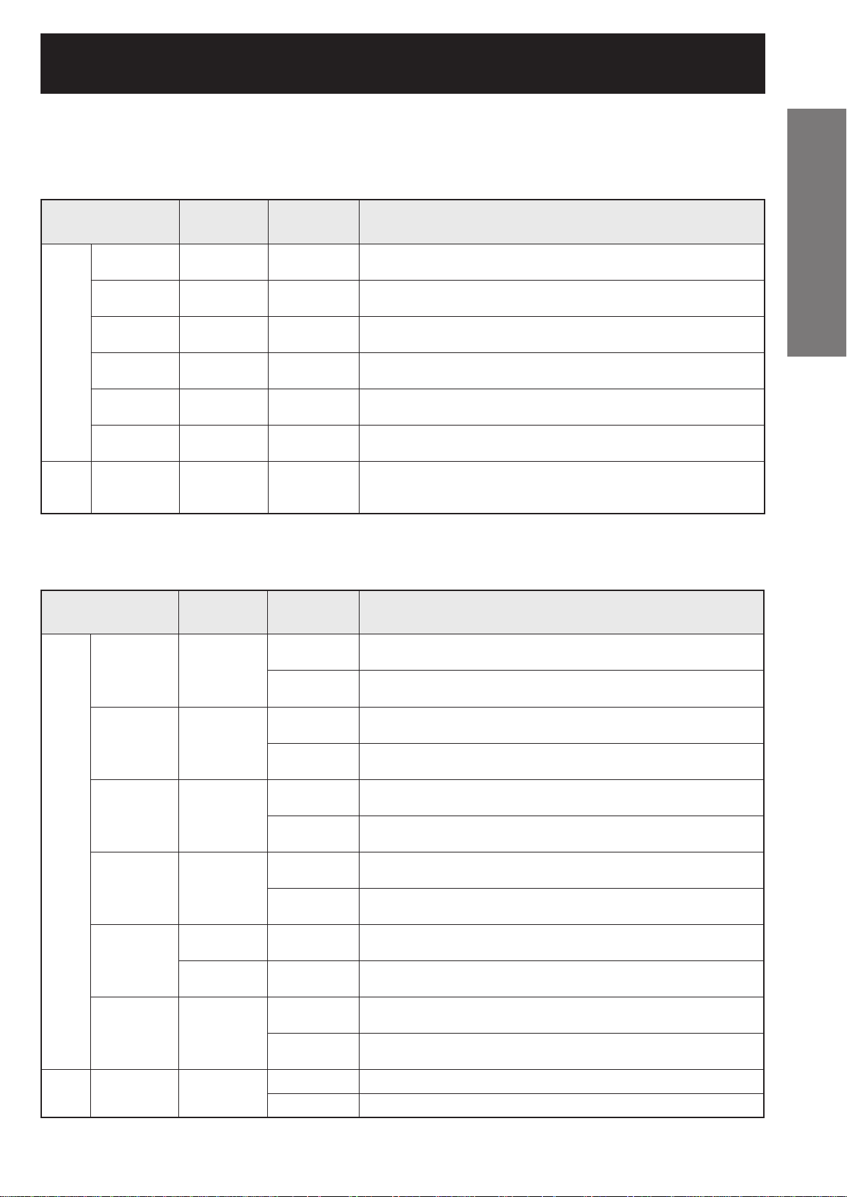
If the projector is used with a screen size not listed in this manual, check the diagonal dimension (inch) of your
screen and calculate the projection distance using the following formulas.
Calculation formulas for projection distance by lens types
■
(for PT-DW10000U)
Model number of
Model number of
projection lens
projection lens
ET-D75LE1 1.4-1.8 : 1 16:9
ET-D75LE1 1.4-1.8 : 1 16:9
ET-D75LE2 1.8-2.8 : 1 16:9
ET-D75LE2 1.8-2.8 : 1 16:9
ET-D75LE3 2.8-4.6 : 1 16:9
Zoom
Zoom
lens
lens
Fixed-
Fixed-
focus
focus
lens
lens
ET-D75LE3 2.8-4.6 : 1 16:9
ET-D75LE4 4.6-7.4 : 1 16:9
ET-D75LE4 4.6-7.4 : 1 16:9
ET-D75LE8 7.3-13.8 : 1 16:9
ET-D75LE8 7.3-13.8 : 1 16:9
ET-D75LE6 0.9-1.1 : 1 16:9
ET-D75LE6 0.9-1.1 : 1 16:9
ET-D75LE5 0.7 : 1 16:9 L= 0.0158 × Screen diagonal (inch) – 0.0835
ET-D75LE5 0.7 : 1 16:9 L= 0.0158 × Screen diagonal (inch) – 0.0835
Throw ratio Aspect ratio Projection distance (L) formula Units: m
Throw ratio Aspect ratio Projection distance (L) formula Units: m
Minimal distance: L=0.0307 × Screen diagonal (inch) – 0.0760
Minimal distance: L=0.0307 × Screen diagonal (inch) – 0.0760
Maximal distance: L=0.0410 × Screen diagonal (inch) – 0.1004
Maximal distance: L=0.0410 × Screen diagonal (inch) – 0.1004
Minimal distance: L=0.0412 × Screen diagonal (inch) – 0.0795
Minimal distance: L=0.0412 × Screen diagonal (inch) – 0.0795
Maximal distance: L=0.0617 × Screen diagonal (inch) – 0.1064
Maximal distance: L=0.0617 × Screen diagonal (inch) – 0.1064
Minimal distance: L=0.0617 × Screen diagonal (inch) – 0.0958
Minimal distance: L=0.0617 × Screen diagonal (inch) – 0.0958
Maximal distance: L=0.1031 × Screen diagonal (inch) – 0.1216
Maximal distance: L=0.1031 × Screen diagonal (inch) – 0.1216
Minimal distance: L=0.1031 × Screen diagonal (inch) – 0.1158
Minimal distance: L=0.1031 × Screen diagonal (inch) – 0.1158
Maximal distance: L=0.1639 × Screen diagonal (inch) – 0.1013
Maximal distance: L=0.1639 × Screen diagonal (inch) – 0.1013
Minimal distance: L=0.1640 × Screen diagonal (inch) – 0.3862
Minimal distance: L=0.1640 × Screen diagonal (inch) – 0.3862
Maximal distance: L=0.3072 × Screen diagonal (inch) – 0.3598
Maximal distance: L=0.3072 × Screen diagonal (inch) – 0.3598
Minimal distance: L=0.0207 × Screen diagonal (inch) – 0.0566
Minimal distance: L=0.0207 × Screen diagonal (inch) – 0.0566
Maximal distance: L=0.0248 × Screen diagonal (inch) – 0.0736
Maximal distance: L=0.0248 × Screen diagonal (inch) – 0.0736
Getting Started
Calculation formulas for projection distance by lens types
■
(for PT-D10000U)
Model number of
Model number of
projection lens
projection lens
ET-D75LE1 1.5-2.0 : 1
ET-D75LE1 1.5-2.0 : 1
ET-D75LE2 2.0-3.0 : 1
ET-D75LE2 2.0-3.0 : 1
ET-D75LE3 3.0-5.0 : 1
ET-D75LE3 3.0-5.0 : 1
Zoom
Zoom
lens
lens
ET-D75LE4 5.0-8.0 : 1
ET-D75LE4 5.0-8.0 : 1
ET-D75LE8
ET-D75LE8
ET-D75LE6 1.0-1.2 : 1
ET-D75LE6 1.0-1.2 : 1
Fixed-
Fixed-
focus
focus
lens
lens
ET-D75LE5 0.8 : 1
ET-D75LE5 0.8 : 1
Throw ratio Aspect ratio Projection distance (L) formula Units: m
Throw ratio Aspect ratio Projection distance (L) formula Units: m
Minimal distance: L=0.0307 × Screen diagonal (inch) – 0.0760
4:3
4:3
16:9
16:9
4:3
4:3
16:9
16:9
4:3
4:3
16:9
16:9
4:3
4:3
16:9
16:9
7.9-15.0 : 1 4:3
7.9-15.0 : 1 4:3
8.0-15.0 : 1 16:9
8.0-15.0 : 1 16:9
4:3
4:3
16:9
16:9
4:3 L= 0.0158 × Screen diagonal (inch) – 0.0835
4:3 L= 0.0158 × Screen diagonal (inch) – 0.0835
16:9 L= 0.0172 × Screen diagonal (inch) – 0.0835
16:9 L= 0.0172 × Screen diagonal (inch) – 0.0835
Minimal distance: L=0.0307 × Screen diagonal (inch) – 0.0760
Maximal distance: L=0.0410 × Screen diagonal (inch) – 0.1004
Maximal distance: L=0.0410 × Screen diagonal (inch) – 0.1004
Minimal distance: L=0.0334 × Screen diagonal (inch) – 0.0760
Minimal distance: L=0.0334 × Screen diagonal (inch) – 0.0760
Maximal distance: L=0.0446 × Screen diagonal (inch) – 0.1004
Maximal distance: L=0.0446 × Screen diagonal (inch) – 0.1004
Minimal distance: L=0.0412 × Screen diagonal (inch) – 0.0795
Minimal distance: L=0.0412 × Screen diagonal (inch) – 0.0795
Maximal distance: L=0.0617 × Screen diagonal (inch) – 0.1064
Maximal distance: L=0.0617 × Screen diagonal (inch) – 0.1064
Minimal distance: L=0.0448 × Screen diagonal (inch) – 0.0795
Minimal distance: L=0.0448 × Screen diagonal (inch) – 0.0795
Maximal distance: L=0.0672 × Screen diagonal (inch) – 0.1064
Maximal distance: L=0.0672 × Screen diagonal (inch) – 0.1064
Minimal distance: L=0.0617 × Screen diagonal (inch) – 0.0958
Minimal distance: L=0.0617 × Screen diagonal (inch) – 0.0958
Maximal distance: L=0.1031 × Screen diagonal (inch) – 0.1216
Maximal distance: L=0.1031 × Screen diagonal (inch) – 0.1216
Minimal distance: L=0.0672 × Screen diagonal (inch) – 0.0958
Minimal distance: L=0.0672 × Screen diagonal (inch) – 0.0958
Maximal distance: L=0.1123 × Screen diagonal (inch) – 0.1216
Maximal distance: L=0.1123 × Screen diagonal (inch) – 0.1216
Minimal distance: L=0.1031 × Screen diagonal (inch) – 0.1158
Minimal distance: L=0.1031 × Screen diagonal (inch) – 0.1158
Maximal distance: L=0.1639 × Screen diagonal (inch) – 0.1013
Maximal distance: L=0.1639 × Screen diagonal (inch) – 0.1013
Minimal distance: L=0.1123 × Screen diagonal (inch) – 0.1158
Minimal distance: L=0.1123 × Screen diagonal (inch) – 0.1158
Maximal distance: L=0.1786 × Screen diagonal (inch) – 0.1013
Maximal distance: L=0.1786 × Screen diagonal (inch) – 0.1013
Minimal distance: L=0.1640 × Screen diagonal (inch) – 0.3862
Minimal distance: L=0.1640 × Screen diagonal (inch) – 0.3862
Maximal distance: L=0.3072 × Screen diagonal (inch) – 0.3598
Maximal distance: L=0.3072 × Screen diagonal (inch) – 0.3598
Minimal distance: L=0.1786 × Screen diagonal (inch) – 0.3862
Minimal distance: L=0.1786 × Screen diagonal (inch) – 0.3862
Maximal distance: L=0.3346 × Screen diagonal (inch) – 0.3598
Maximal distance: L=0.3346 × Screen diagonal (inch) – 0.3598
Minimal distance: L=0.0207 × Screen diagonal (inch) – 0.0566
Minimal distance: L=0.0207 × Screen diagonal (inch) – 0.0566
Maximal distance: L=0.0248 × Screen diagonal (inch) – 0.0736
Maximal distance: L=0.0248 × Screen diagonal (inch) – 0.0736
Minimal distance: L=0.0225 × Screen diagonal (inch) – 0.0566
Minimal distance: L=0.0225 × Screen diagonal (inch) – 0.0566
Maximal distance: L=0.0270 × Screen diagonal (inch) – 0.0736
Maximal distance: L=0.0270 × Screen diagonal (inch) – 0.0736
ENGLISH – 23

Connection
Before starting connection
Before connection, read carefully the instruction manual for the device to be connected.
•
Turning off the power switch of the devices before connecting cables.
•
If any connection cable is not supplied with the device, or if no optional cable is available for connection of the
•
device, prepare a necessary system connection cable to suit the device.
Video signals containing too much jitter may cause the images on the screen to randomly wobble or wafture. In
•
this case, a time base corrector (TBC) must be connected.
The projector accepts the following signals: video, S-Video, analog RGB, DVI-D and signals which are compatible
•
with the optional input module (p. 27).
Some PC models cannot be connected to the projector.
•
The pin-out and signal names of the S-VIDEO IN terminal are shown in the diagram below.
●
Pin No. Signal
Pin No. Signal
Ground (luminance signal)
Ground (luminance signal)
Ground (color signal)
Ground (color signal)
Luminance signal
Luminance signal
Color signal
Color signal
Outside view
Outside view
#
#
$
$
%
%
&
&
The pin-out and signal names of the RGB2 IN terminal are shown in the diagram below.
●
Pin No. Signal
Pin No. Signal
R/PR
R/PR
G/G • SYNC/Y
G/G • SYNC/Y
B/PB
B/PB
HD/SYNC
HD/SYNC
VD
VD
Outside view
Outside view
#
#
$
$
%
%
1
1
2
2
&, -, 0, and 3 are not assigned.
( - +, . and / are GND terminals.
●
The pin-out and signal names of the DVI-D IN terminal are shown in the diagram below.
=
4
4
=
Outside view
Outside view
5
5
#+
#+
-
-
Pin
Pin
No.
No.
T.M.D.S data 2–
T.M.D.S data 2–
#
#
T.M.D.S data 2+
T.M.D.S data 2+
$
$
T.M.D.S data 2 / 4 shield
T.M.D.S data 2 / 4 shield
%
%
&5
&5
(6
(6
DDC clock
DDC clock
)
)
DDC data
DDC data
*
*
+8
+8
T.M.D.S data 1–
T.M.D.S data 1–
-
-
T.M.D.S data 1+
T.M.D.S data 1+
.
.
T.M.D.S data 1 / 3 shield
T.M.D.S data 1 / 3 shield
/
/
0=
0=
Signal
Signal
Pin
Pin
No.
No.
1
1
+5V
+5V
2
2
Ground
Ground
3
3
Hot plug detection
Hot plug detection
4
4
T.M.D.S data 0-
T.M.D.S data 0T.M.D.S data 0+
T.M.D.S data 0+
T.M.D.S data 0 / 5 shield
T.M.D.S data 0 / 5 shield
7
7
9
9
T.M.D.S clock shield
T.M.D.S clock shield
:
:
T.M.D.S clock+
T.M.D.S clock+
;
;
T.M.D.S clock–
T.M.D.S clock–
Signal
Signal
24 – ENGLISH
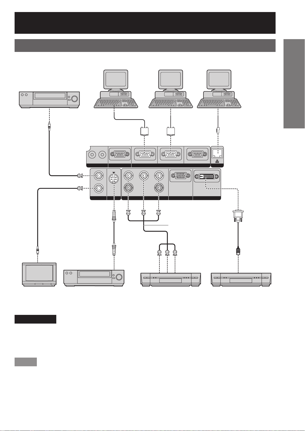
Example of connecting with VIDEO devices
Control PC
Video deck (TBC built-in)
Video deck (TBC built-in)
IN OUT
IN OUT
OUT
OUT
VIDEO
VIDEO
Control PC
IN
IN
S-VIDEO IN
S-VIDEO IN
RS-232C IN RS-422 IN
RS-232C IN RS-422 IN
R
R
SYNC/HD VD
SYNC/HD VD
RGB 1 IN
RGB 1 IN
G/YR/P
G/YR/P
Control PC
Control PC
SERIALREMOTE 1 REMOTE 2 IN
SERIALREMOTE 1 REMOTE 2 IN
B/P
B/P
B
B
RGB 2 IN
RGB 2 IN
RS-422 OUT
RS-422 OUT
DVI-D IN
DVI-D IN
Control PC
Control PC
LAN
LAN
Getting Started
Red (connected to PR terminal)
Red (connected to PR terminal)
Blue (connected to P
Blue (connected to P
Green (connected to Y terminal)
Green (connected to Y terminal)
Color monitor Video deck (TBC built-in) High-vision video deck
Color monitor Video deck (TBC built-in) High-vision video deck
B terminal)
B terminal)
DVD player with HDMI
DVD player with HDMI
(HDCP) terminal
(HDCP) terminal
Attention
When connecting with a video deck, be sure to use the one with a built-in time base corrector (TBC) or use a
•
TBC between the projector and the video deck.
If nonstandard burst signals are connected, the image may be distorted. If this is the case, connect a TBC
•
between the projector and the video deck.
Note
The DVI-D signal input terminal supports only a single link.
•
The HDMI-DVI-D conversion cable is required to connect an HDMI-compliant device.
•
The EDID mode setting must be selected so that it corresponds to the device to be connected. (
•
It is possible to connect the DVI-D input terminal with an HDMI- or DVI-D-compliant device, but with some
•
devices the images may not appear or other problems may be encountered in operation.
pp. 71, 72)
ENGLISH – 25
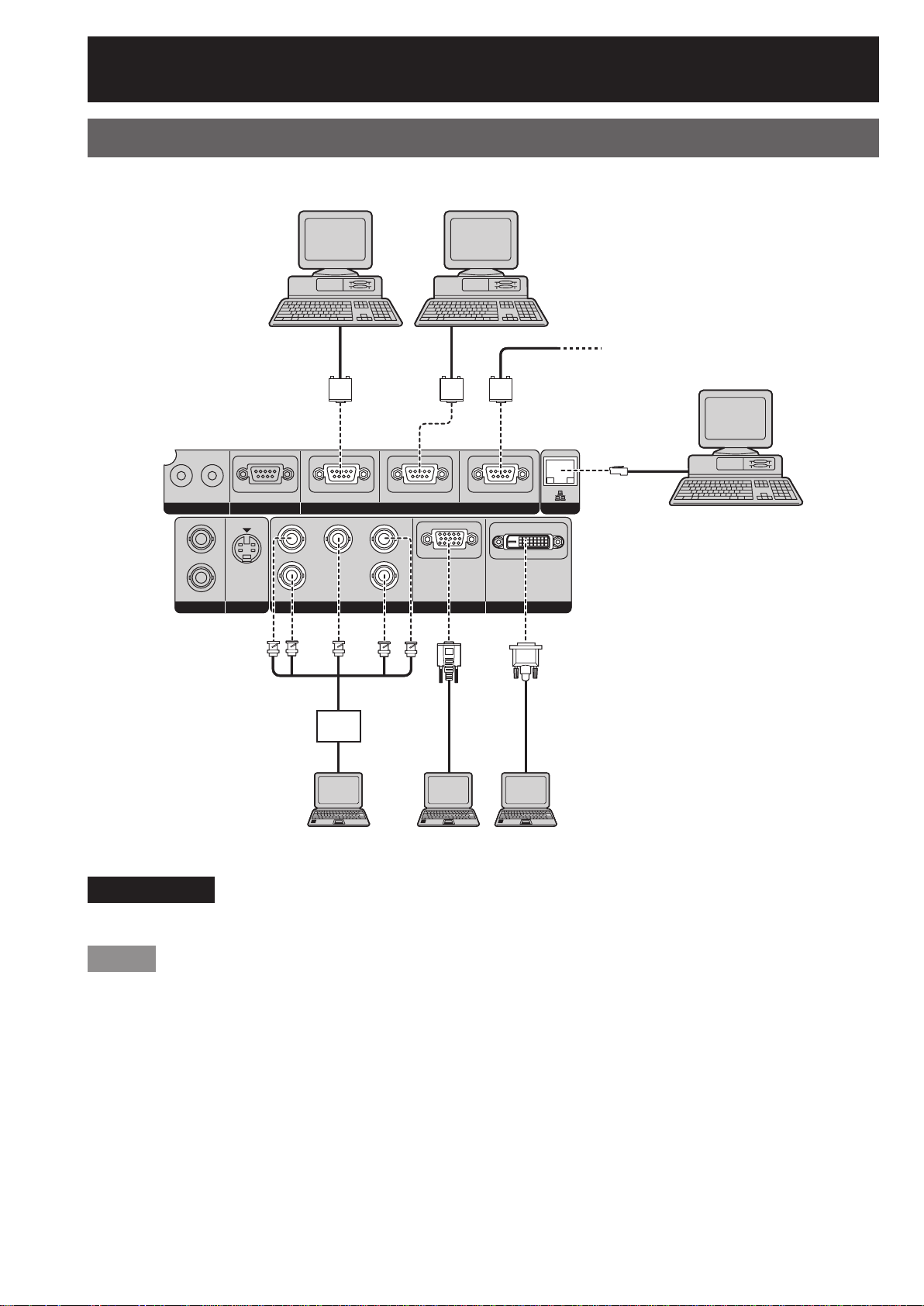
Connection (continued)
Example of connecting with personal computers
Control PCControl PC
Control PCControl PC
To 2nd projector
To 2nd projector
(SERIAL IN terminal)
(SERIAL IN terminal)
IN OUT
IN OUT
RS-232C IN RS-422 IN
RS-232C IN RS-422 IN
SERIALREMOTE 1 REMOTE 2 IN
SERIALREMOTE 1 REMOTE 2 IN
RS-422 OUT
RS-422 OUT
LAN
LAN
Control PC
Control PC
B/P
B/P
B
B
RGB 2 IN
RGB 2 IN
PC PC
PC PC
DVI-D IN
DVI-D IN
VIDEO
VIDEO
IN
IN
OUT
OUT
S-VIDEO IN
S-VIDEO IN
G/YR/P
R
G/YR/P
R
SYNC/HD VD
SYNC/HD VD
RGB 1 IN
RGB 1 IN
I/F
I/F
PC
PC
Attention
When the main power of the main unit is turned off, also turn off the power of the PC.
•
Note
For the specifications of the RGB signals that can be applied from the PC, see the data sheet on page 118.
•
If your PC has the resume feature (last memory), the computer may not function properly until the resume
•
capability is disabled.
26 – ENGLISH
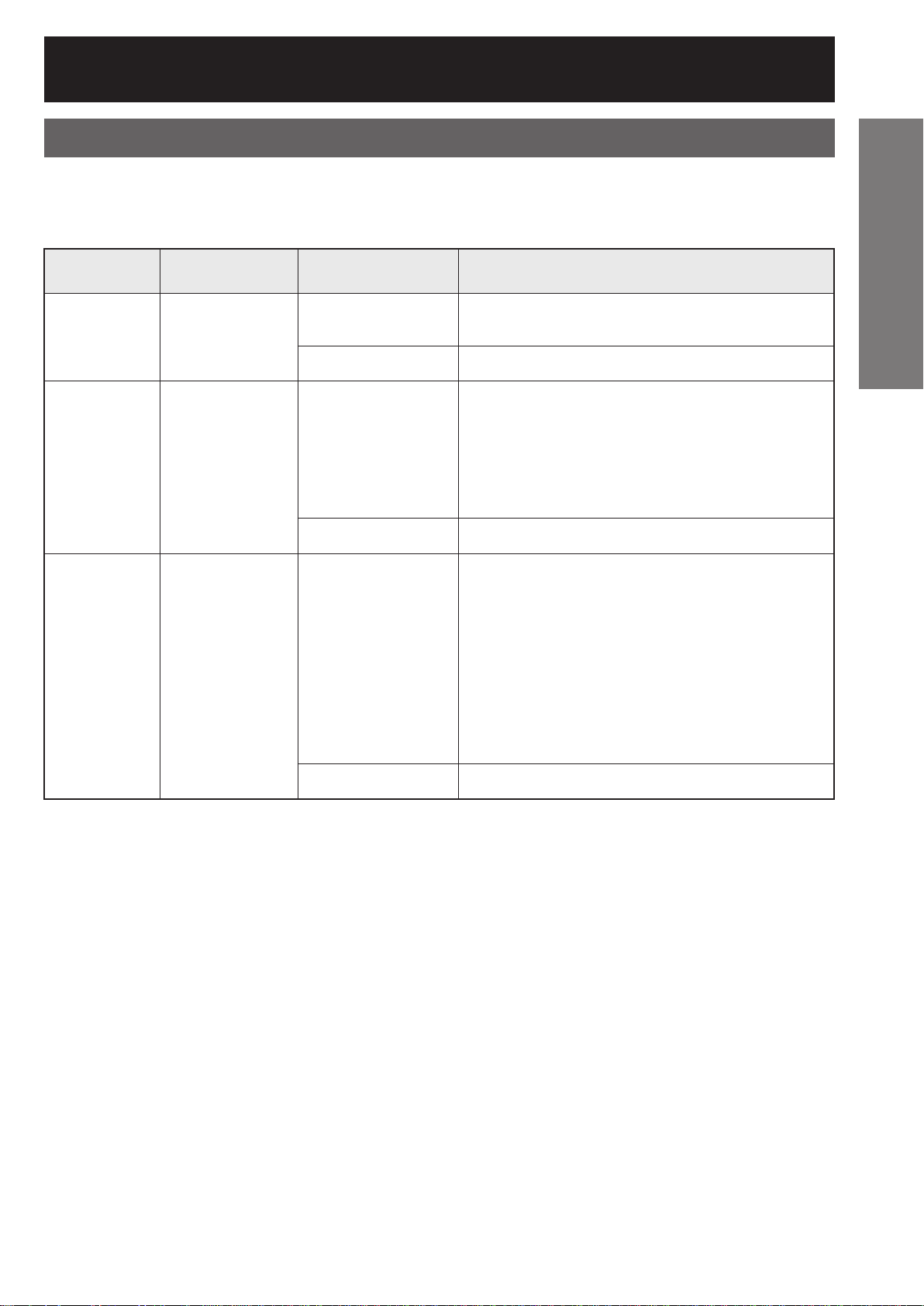
Installation of input module (optional)
Installing the input module
Types of the input modules (optional)
■
Prepare beforehand an input module (optional) compatible with the input signals of the system.
Module model
Module
Module
SD-SDI
SD-SDI
input module
input module
HD/SD-SDI
HD/SD-SDI
input module
input module
Module model
No.
No.
ET-MD77SD1
ET-MD77SD1
ET-MD77SD3
ET-MD77SD3
Terminal Signal formats supported
Terminal Signal formats supported
BNC input × 1
BNC input × 1
BNC output × 1
BNC output × 1
RJ-45 input × 1
RJ-45 input × 1
BNC input × 1
BNC input × 1
BNC output × 1
BNC output × 1
*1
*1
SMPTE259M compliant : 480i, 576i
SMPTE259M compliant : 480i, 576i
10BASE-T/100BASE-TX
10BASE-T/100BASE-TX
SMPTE259M compliant : 480i, 576i
SMPTE259M compliant : 480i, 576i
SMPTE292M compliant :
SMPTE292M compliant :
720/60p, 720/59.94p, 720/50p
720/60p, 720/59.94p, 720/50p
1 035/60i, 1 035/59.94i, 1 080/60i, 1 080/59.94i
1 035/60i, 1 035/59.94i, 1 080/60i, 1 080/59.94i
1 080/50i, 1 080/24sF, 1 080/23.98sF, 1 080/30p
1 080/50i, 1 080/24sF, 1 080/23.98sF, 1 080/30p
1 080/29.97p, 1 080/25p, 1 080/24p, 1 080/23.98p
1 080/29.97p, 1 080/25p, 1 080/24p, 1 080/23.98p
Getting Started
*1
*1
*1
*1
10BASE-T/100BASE-TX
10BASE-T/100BASE-TX
*2
*2
DVI-D single link, DVI 1.0 compliant
HDCP-compliant
HDCP-compliant
EDID1 :
EDID1 :
480p, 576p, 720/60p, 720/59.94p, 720/50p
480p, 576p, 720/60p, 720/59.94p, 720/50p
1 080/60i, 1 080/59.94i, 1 080/50i, 1 080/24sF,
1 080/60i, 1 080/59.94i, 1 080/50i, 1 080/24sF,
1 080/23.98sF
1 080/23.98sF
1 080/30p, 1 080/29.97p, 1 080/25p, 1 080/24p,
1 080/30p, 1 080/29.97p, 1 080/25p, 1 080/24p,
1 080/23.98p, 1 080/50p, 1 080/59.94p, 1 080/60p
1 080/23.98p, 1 080/50p, 1 080/59.94p, 1 080/60p
EDID2 :
EDID2 :
Displayable resolution VGA - UXGA (non-interlace)
Displayable resolution VGA - UXGA (non-interlace)
Dot clock frequency 25 - 162 MHz
Dot clock frequency 25 - 162 MHz
10BASE-T/100BASE-TX
10BASE-T/100BASE-TX
DVI-D single link, DVI 1.0 compliant
DVI-D
DVI-D
input module
input module
ET-MD77DV
ET-MD77DV
RJ-45 input × 1
RJ-45 input × 1
DVI-D 24p
DVI-D 24p
input × 1
input × 1
RJ-45 input × 1
RJ-45 input × 1
*1: The LAN terminal of the input module (optional) cannot be used with the PT-D10000U/PT-DW10000U. Use the
LAN terminal that is provided as standard with the projector.
*2: HDCP (High-bandwidth Digital Content Protection)
HDCP is a specification for encoding digital image signals which was developed to protect digital content.
The DVI-D/HDMI output signals from the HDCP-compliant equipment have been encoded by the HDCP
specifications to ensure content protection, but the DVI-D input module is capable of displaying the digital
images properly since it complies with the HDCP specification.
ENGLISH – 27
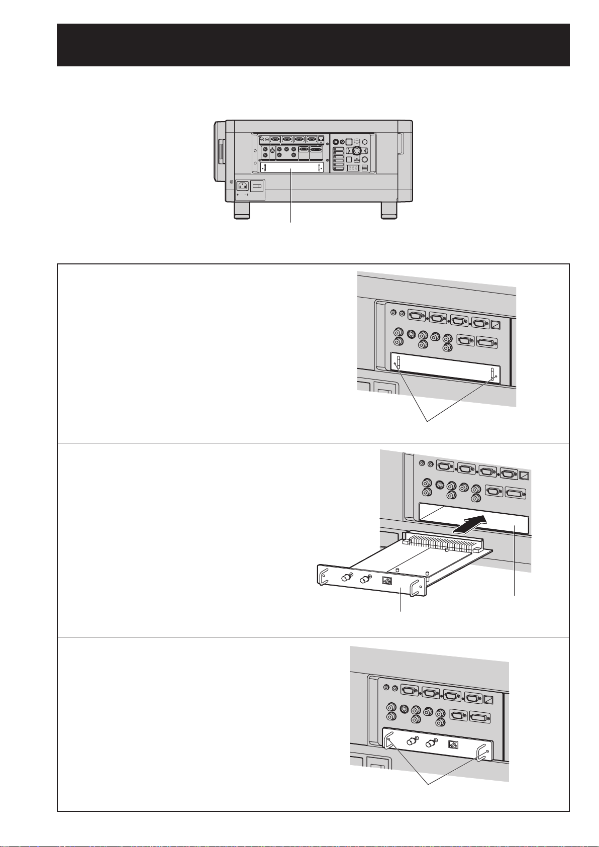
Installation of input module (optional) (continued)
Procedure of installation
■
Disconnect the power before installing the input module.
MENU LENS
MENU LENS
LAN
LAN
POWER ON STANDBY
POWER ON STANDBY
VIDEO
VIDEO
ENTER
ENTER
S-VIDEO
S-VIDEO
RGB1
RGB1
AUTO
AUTO
SHUTTER
SHUTTER
SETUP
SETUP
RGB2
RGB2
LIGHT
LIGHT
DVI-D
DVI-D
ON
ON
AUX
AUX
OFF
OFF
1. Remove the slot cover.
1. Remove the slot cover.
OFF ON
OFF ON
AC IN
AC IN
MAIN POWER
MAIN POWER
IN OUT
IN OUT
RS-232C IN RS-422 IN RS-422 OUT
RS-232C IN RS-422 IN RS-422 OUT
REMOTE 1 REMOTE 2 IN
REMOTE 1 REMOTE 2 IN
G/YR/P
R
G/YR/P
R
IN
IN
SYNC/HD VD
SYNC/HD VD
OUT
OUT
S-VIDEO IN
VIDEO RGB 2 IN
RGB 1 IN
S-VIDEO IN
VIDEO RGB 2 IN
RGB 1 IN
Slot Cover
Slot Cover
SERIAL
SERIAL
B/P
B/P
B
B
DVI-D IN
DVI-D IN
2. Insert the input module.
2. Insert the input module.
3. Fix the input module.
3. Fix the input module.
4. Register the input signal.
4. Register the input signal.
This projector needs to register the type of
•
This projector needs to register the type of
•
input signal after the installation of the input
input signal after the installation of the input
module.
module.
For details on the registration of the input
•
For details on the registration of the input
•
signals, refer to pages 40-42.
signals, refer to pages 40-42.
Remove 2 screws.
Remove 2 screws.
Input module
Input module
Slot
Slot
28 – ENGLISH
Tighten the two screws.
Tighten the two screws.
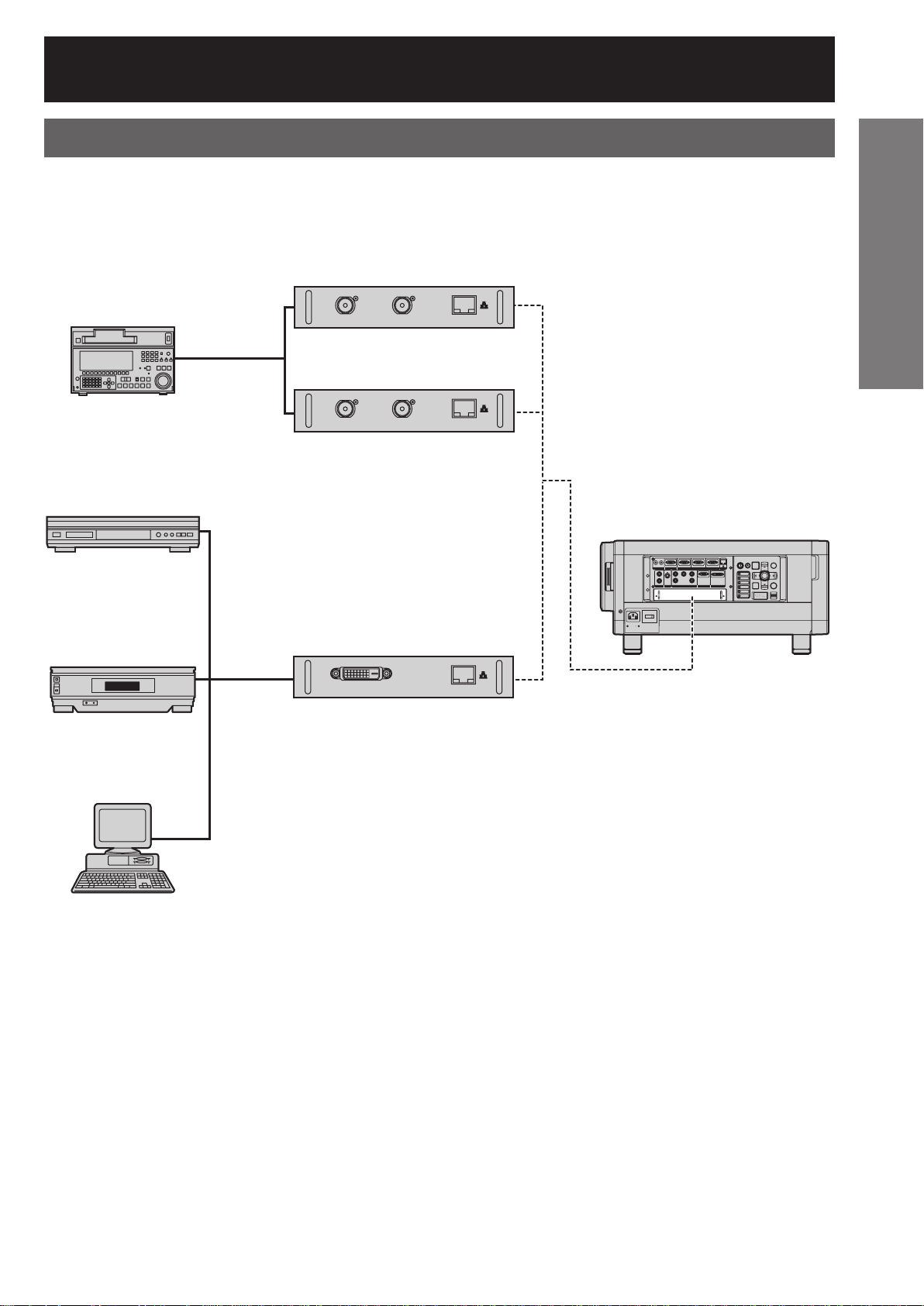
Connecting signals to the input module
When installing the projector, it is necessary to connect signals to the input module in accordance with the
connecting equipment.
Refer to the following diagram to establish proper signal connection.
SD-SDI input
SD-SDI input
module ET-MD77SD1
module ET-MD77SD1
Business digital
Business digital
VCR
VCR
SDI
SDI
signal
DVD player
DVD player
High-vision
High-vision
video deck
video deck
signal
DVI-D
DVI-D
signal
signal
HD/SD-SDI input
HD/SD-SDI input
module ET-MD77SD3
module ET-MD77SD3
DVI-D input module
DVI-D input module
ET-MD77DV
ET-MD77DV
AC IN
AC IN
IN OUT
IN OUT
REMOTE 1 REMOTE 2 IN
REMOTE 1 REMOTE 2 IN
IN
IN
OUT
OUT
S-VIDEO IN
VIDEO RGB 2 IN
S-VIDEO IN
VIDEO RGB 2 IN
OFF ON
OFF ON
MAIN POWER
MAIN POWER
Projector
Projector
RS-232C IN RS-422 IN RS-422 OUT
RS-232C IN RS-422 IN RS-422 OUT
SERIAL
SERIAL
B
G/YR/P
R
B
G/YR/P
R
B/P
B/P
SYNC/HD VD
SYNC/HD VD
DVI-D IN
DVI-D IN
RGB 1 IN
RGB 1 IN
MENU LENS
MENU LENS
LAN
LAN
POWER ON STANDBY
POWER ON STANDBY
VIDEO
VIDEO
S-VIDEO
S-VIDEO
RGB1
RGB1
AUTO
AUTO
SETUP
SETUP
RGB2
RGB2
DVI-D
DVI-D
AUX
AUX
Getting Started
ENTER
ENTER
SHUTTER
SHUTTER
LIGHT
LIGHT
ON
ON
OFF
OFF
PC
PC
ENGLISH – 29
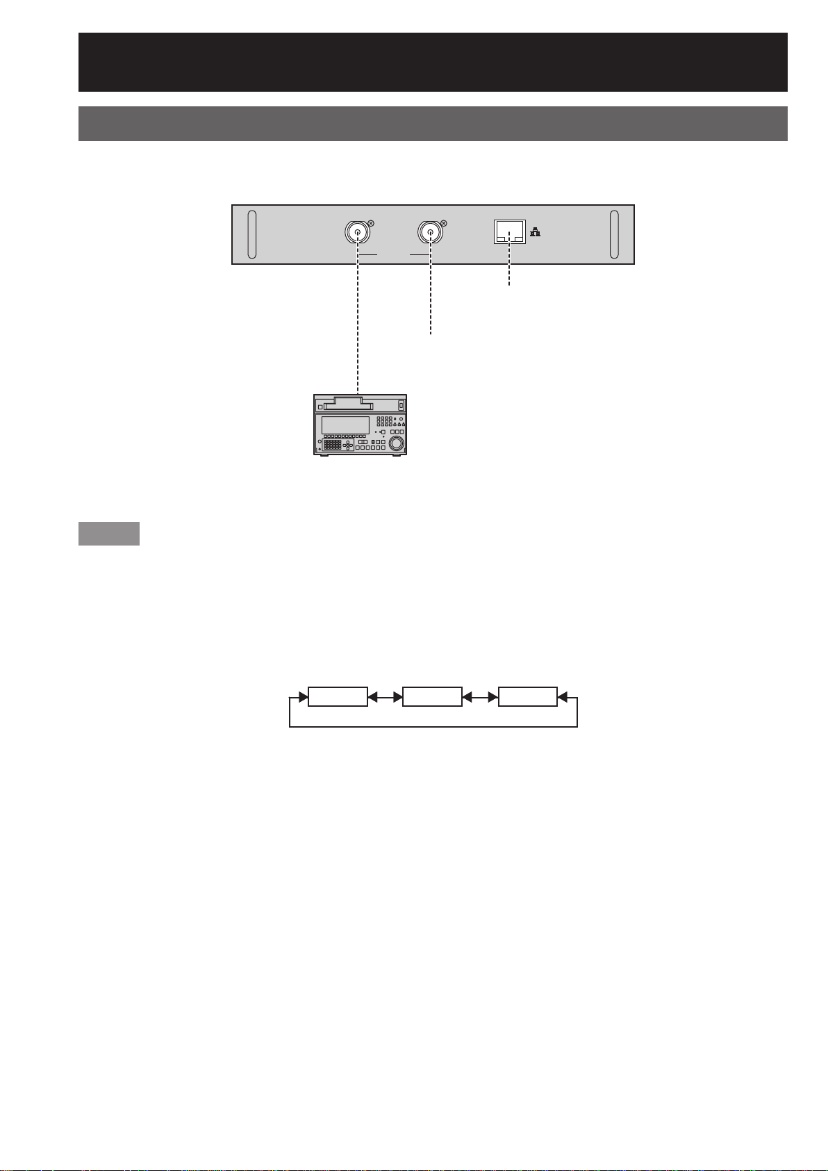
Installation of input module (optional) (continued)
Connecting the signal to the SD-SDI input module
SD-SDI input module (optional)
SD-SDI input module (optional)
ET-MD77SD1 (for 480i/576i)
ET-MD77SD1 (for 480i/576i)
SD-SDI Module
SD-SDI Module
ET-MD77SD1
ET-MD77SD1
SD-SDI signal SD-SDI signal output
SD-SDI signal SD-SDI signal output
Business digital
Business digital
IN
IN
SERIAL
SERIAL
(active through)
(active through)
VCR
VCR
OUT
OUT
(10BASE-T/100BASE-TX)
(10BASE-T/100BASE-TX)
LAN
LAN
LAN terminal
LAN terminal
*1
*1
Note
Insert the input module suitable for the input signal specifications.
•
Normally, use SYSTEM SELECTOR in “AUTO”.
•
If a source with an unstable signal is connected, errors in automatic signal recognition may occur. If this happens,
•
use the SYSTEM SELECTOR menu to switch the format to the one which matches the signals being input.
If using an input module which supports two different signal specifications, use the SYSTEM SELECTOR menu
•
to toggle between the two different types of signal. When this is done, the input signal details will appear on the
screen momentarily and then disappear automatically.
AUTO 480i 576iAUTO 480i 576i
*1: The LAN terminal of the input module (optional) cannot be used with the PT-D10000U/PT-DW10000U. Use the
LAN terminal that is provided as standard with the projector.
30 – ENGLISH