

Panasonic PT-D10000U, PT-D10000E, PT-DW10000U, PT-DW10000E Service Manual
DLP Based Projector
PT-D10000U
PT-D10000E
PT-DW10000U
PT-DW10000E
ORDER NO. VED0612375C0
D10
© 2006 Matsushita Electric Industrial Co., Ltd. All
rights reserved. Unauthorized copying and
distribution is a violation of law.
PT-D10000U / PT-D10000E / PT-DW10000U / PT-DW10000E
2

PT-D10000U / PT-D10000E / PT-DW10000U / PT-DW10000E
CONTENTS
Page Page
1 Safety Precautions 5
1.1. General Guidelines
1.2. Leakage Current Check
1.3. UV Precaution and UHM Lamp Precautions
2 Specifications
3 Function for Safety
3.1. Temperature Detection inside the Lamp Unit
3.2. Interlock Switch
4 Serviceman Mode
4.1. Setting to Serviceman Mode
4.2. Resetting to User Mode
4.3. Functions in Serviceman Mode
5 Self-diagnosis Display
5.1. Error-code Table
6 Using the Serial Terminals
6.1. Example of Connection
6.2. Pin Assignments and Signal Names
6.3. Communication Conditions (Factory Setting)
6.4. Procedure of Communication Condition Settings
6.5. Control commands
6.6. Cable specifications
7 Using a Wired Remote Control
7.1. Connection Example
7.2. Setting Projector ID Number to Remote Control
8 Support for Service
8.1. Supporting Methods
8.2. Note for Replacement of A-P.C.Board
8.3. Replacement of the lithium battery on the A-P.C.Board
9 Cautions for Service
9.1. Servicing Methods
10 Parts Location
10.1. Electrical Parts Location
10.2. Electromechanical Parts Location
11 Replacement of Lamp Unit
11.1. Precautions on Lamp Unit Replacement
11.2. Timing of Lamp Unit Replacement
11.3. Indication of Lamp Monitor
12 Disassembly Instructions
12.1. Flowchart for Disassembly
12.2. Removal of Upper Case
12.3. Removal of A-P.C.Board
12.4. Removal of CL-P.C.Board
12.5. Removal of FH-Module
12.6. Removal of G-P.C.Board
12.7. Removal of J-P.C.Board
12.8. Removal of J2-/J3-P.C.Board
12.9. Removal of L1-/L2-/L3-/L4-P.C.Board
12.10. Removal of NN-Module
12.11. Removal of R-P.C.Board
12.12. Removal of R2-P.C.Board
12.13. Removal of R3-P.C.Board
10
10
14
14
17
17
18
18
18
19
19
21
21
21
22
22
22
22
22
22
23
23
23
24
24
24
25
26
26
27
28
28
29
29
31
31
32
33
33
34
35
12.14. Removal of S-P.C.Board
5
5
5
6
8
8
8
8
9
12.15. Removal of SL-P.C.Board
12.16. Removal of K-Module
12.17. Removal of B/Q-Module
12.18. Removal of PF-Modele
12.19. Removal of PC-Module
12.20. Removal of Projection Lens
12.21. Removal of Lamp Unit
12.22. Removal of Iris Unit
12.23. Removal of Analysis Block
12.24. Removal of Color Prism Block
12.25. Removal of DMD Block and Liquid Cooling Unit
12.26. Removal of Analysis Mirror
12.27. Removal of Lens Mount Unit
13 Tr oubleshooting
14 Int erc onnection Block Diagram
14.1. Interconnection Block Diagram (1/4)
14.2. Interconnection Block Diagram (2/4)
14.3. Interconnection Block Diagram (3/4)
14.4. Interconnection Block Diagram (4/4) (PT-D10000U/E)
14.5. Interconnection Block Diagram (4/4) (PT-DW10000U/E)
15 Block Diagram
15.1. Power Supply (1/2)
15.2. Power Supply (2/2)
15.3. Signal Processing (1/2)
15.4. Signal Processing (2/2) (PT-D10000)
15.5. Signal Processing (2/2) (PT-DW10000)
15.6. Control and Driving System (1/2)
15.7. Control and Driving System (2/2)
16 Schematic Diagram
16.1. A-P.C.Board (1/11)
16.2. A-P.C.Board (2/11)
16.3. A-P.C.Board (3/11)
16.4. A-P.C.Board (4/11)
16.5. A-P.C.Board (5/11)
16.6. A-P.C.Board (6/11)
16.7. A-P.C.Board (7/11)
16.8. A-P.C.Board (8/11)
16.9. A-P.C.Board (9/11)
16.10. A-P.C.Board (10/11)
16.11. A-P.C.Board (11/11)
16.12. G-P.C.Board (1/5)
16.13. G-P.C.Board (2/5)
16.14. G-P.C.Board (3/5)
16.15. G-P.C.Board (4/5)
16.16. G-P.C.Board (5/5)
16.17. J-P.C.Board
16.18. J2/J3/L1/L2/L3/L4-P.C.Board
16.19. R/R2/R3/SL/CL-P.C.Board
16.20. S-P.C.Board
16.21. B-Module (1/2)
35
36
36
36
39
39
41
41
42
43
46
46
48
48
49
69
69
70
71
72
73
75
75
76
77
78
79
80
81
83
84
85
86
87
88
89
90
91
92
93
94
95
96
97
98
99
100
101
102
103
104
3

PT-D10000U / PT-D10000E / PT-DW10000U / PT-DW10000E
16.22. B-Module (2/2) 105
17 C irc uit Boards
17.1. A-P.C.Board (Foil Side)
17.2. A-P.C.Board (Component Side)
17.3. G-P.C.Board (Foil Side)
107
107
108
109
17.4. G-P.C.Board (Component Side)
17.5. S-P.C.Board
18 Te rm inal guide of ICs and tr ansis tors
19 Ex ploded View s
20 Replacement Parts List
110
111
113
114
120
4
1 Safety Precautions
1.1. General Guidelines
· For continued safety, no modification of any circuit must be
attempted.
· Unplug the power cord from the power outlet before
disassembling this projector.
· Use correctly the supplied power cord and must ground it.
· It is advisable to use an isolation transformer in the AC
power line before the service.
· Be careful not to touch the rotation part (cooling fan, etc.) of
this projector when you service with the upper case
removed and the power supply turned ON.
· Observe the original lead dress during the service. If a short
circuit is found, replace all the parts overheated or
damaged by the short circuit.
· After the service, all the protective devices such as
insulation barriers, insulation papers, shields, and isolation
R-C combinations must be properly installed.
· After the service, check the leakage current to prevent the
customer from getting an electric shock.
1.2. Leakage Current Check
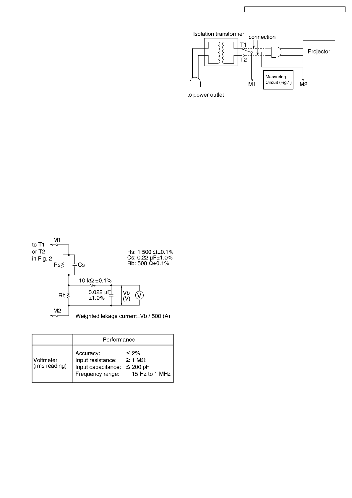
1. Prepare the measuring circuit as shown in Fig.1.
Be sure to use a voltmeter having the performance
described in Table 1.
PT-D10000U / PT-D10000E / PT-DW10000U / PT-DW10000E
Fig. 2
2. Assemble the circuit as shown in Fig. 2. Plug the power
cord in a power outlet.
3. Connect M1 to T1 according to Fig. 2 and measure the
voltage.
4. Change the connection of M1 from T1 to T2 and measure
the voltage again.
5. The voltmeter must read 0.375 V or lower in both of steps
3 and 4. This means that the current must be 0.75 mA or
less.
6. If the reading is out of the above standard, the projector
must be repaired and rechecked before returning to the
customer because of a possibility of an electric shock.
1.3. UV Precaution and UHM Lamp
Precautions
· Be sure to unplug the power cord from the power outlet
when replacing the lamp.
· Because the lamp reaches a very high temperature during
its operation, wait until it cools completely when replacing
the Lamp Unit.
· The lamp emits small amounts of UV-radiation, avoid directeye contact with the light.
· The lamp unit has high internal pressure. If improperly
handled, explosion might result.
Fig. 1
Table 1
5
PT-D10000U / PT-D10000E / PT-DW10000U / PT-DW10000E
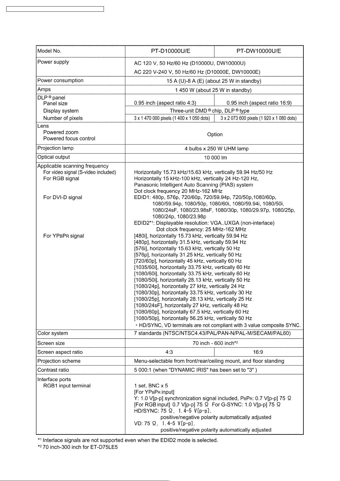
2 Specifications
6
PT-D10000U / PT-D10000E / PT-DW10000U / PT-DW10000E
7
PT-D10000U / PT-D10000E / PT-DW10000U / PT-DW10000E
3 Function for Safety
3.1. Temperature Detection inside the Lamp Unit
This projector has 2 bimetals contacting the lamp units to protect the
lamps.
If the temperature of one of the lamp units exceeds 150°C, the bimetals
will operate to turn off the power. The installed position of the bimetals
is shown in the figure at right.
The reset the bimetal action, press the protrusion of the bimetal unit you
feel a click.
3.2. Interlock Switch
To ensure safety, this projector is designed so that the power cannot be
turned on when the lamp unit cover is opened or installed incorrectly.
If opening the lamp unit cover during operation, the projector will be
switched to standby mode (fans stop and lamps turn off).
4 Serviceman Mode
This projector has Serviceman Mode in addition to standard on-screen menus (User Mode).
8
4.1. Setting to Serviceman Mode
(1) Press the MENU button.
The MAIN MENU screen will be displayed.
(2) Select “OPTION2” using the or buttons and press the
ENTER button.
The OPTION2 screen will be displayed.
(3) Select “PASSWORD” using the or buttons and press the
ENTER button.
The PASSWORD screen will be displayed.
PT-D10000U / PT-D10000E / PT-DW10000U / PT-DW10000E
(4) Input the password "1565" with the numeric buttons (0 to 9) of the
remote control unit and press the ENTER button.
Note:
· Asterisk (*) will appear for the password numbers.
(5) Press the MENU button, then SERVICEMAN MODE menu will be
displayed.
9
PT-D10000U / PT-D10000E / PT-DW10000U / PT-DW10000E
4.2. Resetting to User Mode
(1) Press the MENU button.
The MAIN MENU screen will be displayed.
(2) Select “OPTION2” using the or buttons and press the
ENTER button.
The OPTION2 screen will be displayed.
(3) Select PASSWORD using the or buttons and press the
ENTER button.
The PASSWORD screen will be displayed.
(4) Input the password "0000" with the numeric buttons (0 to 9) of the
remote control unit and press the ENTER button.
Note:
· Asterisk (*) will appear for the password numbers.
(5) Press the MENU button, then USER MODE menu will be displayed.
4.3. Functions in Serviceman Mode
4.3.1. Additional Functions for ADVANCED MENU
· FRAME LOCK
Sets the frame lock.
· V MASK
Sets the V mask.
· PLL SETTING
10

PT-D10000U / PT-D10000E / PT-DW10000U / PT-DW10000E
Sets the VCO and the charge pump.
4.3.2. Additional Functions for OPTION2
· MAX AVAILABLE LAMP
Sets the maximum number of lamps that can be used. Usually, set it to "4".
· AIR FILTER CLEANING
CLEANING menu is added into AIR FILTER CLEANING.
ON: Default setting
OFF: Disables automatic cleaning operation.
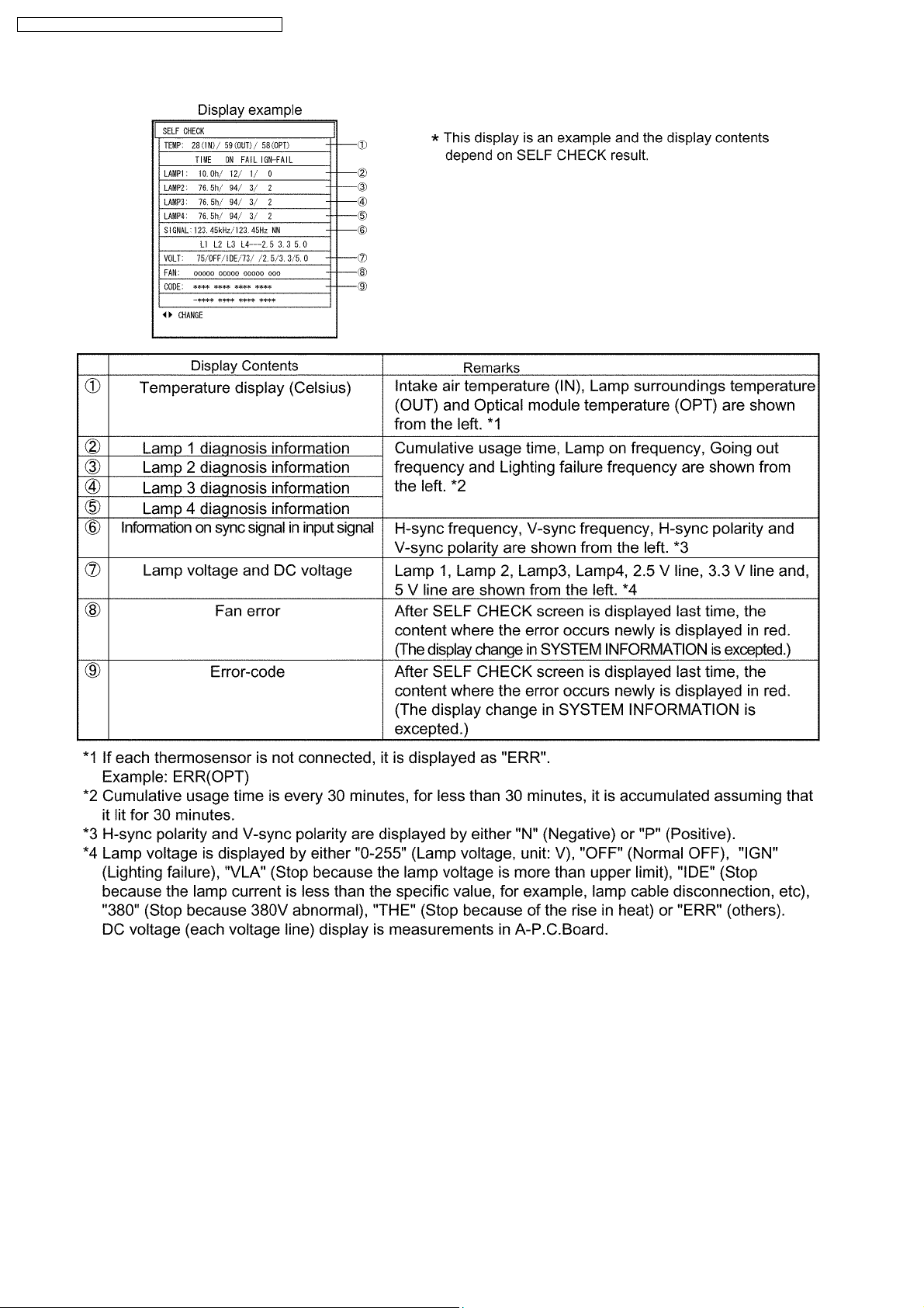
· SYSTEM INFORMATION
The number of pages of screens displayed when selecting becomes "4" in Serviceman Mode from "2" in User Mode.
SELF CHECK
Page 1 and page 2 are the same as User Mode, the display of DDP (formatter software) version is added on page 3 and the
display of SELF CHECK result is added to page 4.
11
PT-D10000U / PT-D10000E / PT-DW10000U / PT-DW10000E
The display contents of SELF CHECK are as follows.
4.3.3. Addition of EXTRA OPTION
· L IGHT OUTPUT
Adjusts brightness with Dynamic Iris. It darkens as the value becomes small.
· CUT OFF
Sets whether to display each color of Red, Green and Blue.
· ENTRY SIGNAL CLEAR
Deletes all entry signals.
· REMOT E 2 MODE
Sets the function of REMOTE2 terminal.
12
[DEFAULT]
[D7700]
PT-D10000U / PT-D10000E / PT-DW10000U / PT-DW10000E
[L6600]
[USER]
Be able to allocate arbitrary input switching functions into the pins 3-7.
Be able to allocate POWER into the pin 2.
Be able to allocate SHUTTER into the pin 8.
· POWER ON SHUTTER
OPEN: Opens the shutter when power ON.
CLOSE: Closes the shutter when power ON.
· POWER OFF SHUTTER
OPEN: Opens the shutter when power OFF.
CLOSE: Closes the shutter when power OFF.
IGNORE: Does not control the shutter when power OFF.
13
PT-D10000U / PT-D10000E / PT-DW10000U / PT-DW10000E
· COLOR FILTER
NONE: Default setting
INSTALLED: When installing the color filter that expands the color region
· UNIFORMITY
Sets the value of color unevenness correction.
· FRONT LAMP LED
ON: Default setting
OFF: Prohibits a green lighting.
· LAMP CHANGE MUTE
ON: Turns off the projection temporarily when switching the lighting lamp.
OFF: Does not turn off the projection when switching the lighting lamp. However, a video noise might appear momentarily in the
projection.
· LENS SHIFT CALIBRATION
Calibrates the limit and the home position of the lens shift.
Execute LENS SHIFT CALIBRATION according to the procedure of the next paragraph when replacing the lens mount, LH-
Module or LV-Module.
4.3.4. Execution of LENS SHIFT CALIBRATION
1. Enter the serviceman mode according to the section 4.1. "Setting to Serviceman Mode".
2. Select LENS SHIFT CALIBRATION in EXTRA OPTION.
3. Press the ENTER button. When you execute LENS SHIFT CALIBRATION, press the ENTER button again when displayed
"SURE?".
4. The lens moves up/down/right/left, and the limit and the home position values of the shift are set again automatically.
5. When the lens stops, re-setting is finished.
5 Self-diagnosis Display
There is a self-diagnosis display located at the side of the projector which automatically displays error details when an error occurs.
If an error-code is displayed in the self-diagnosis display, check the part of the cause according to the content of the error-code
table below.
5.1. Error-code Table
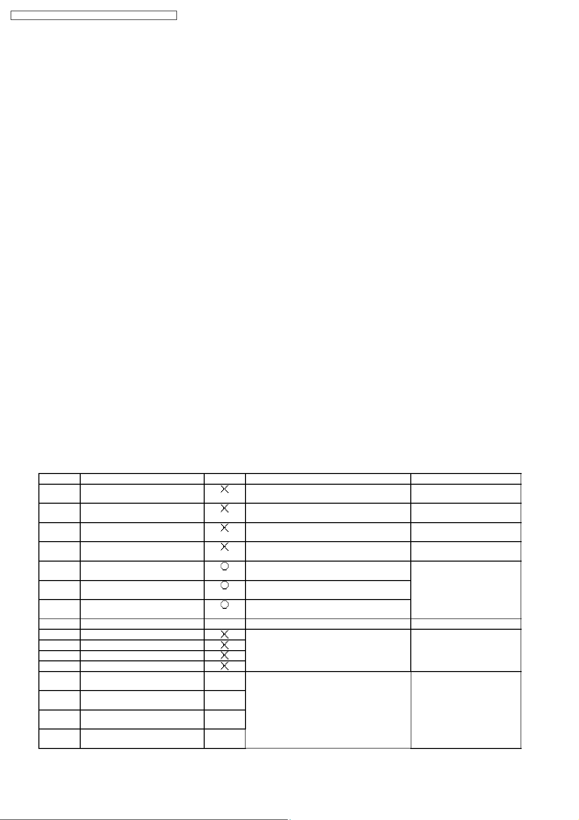
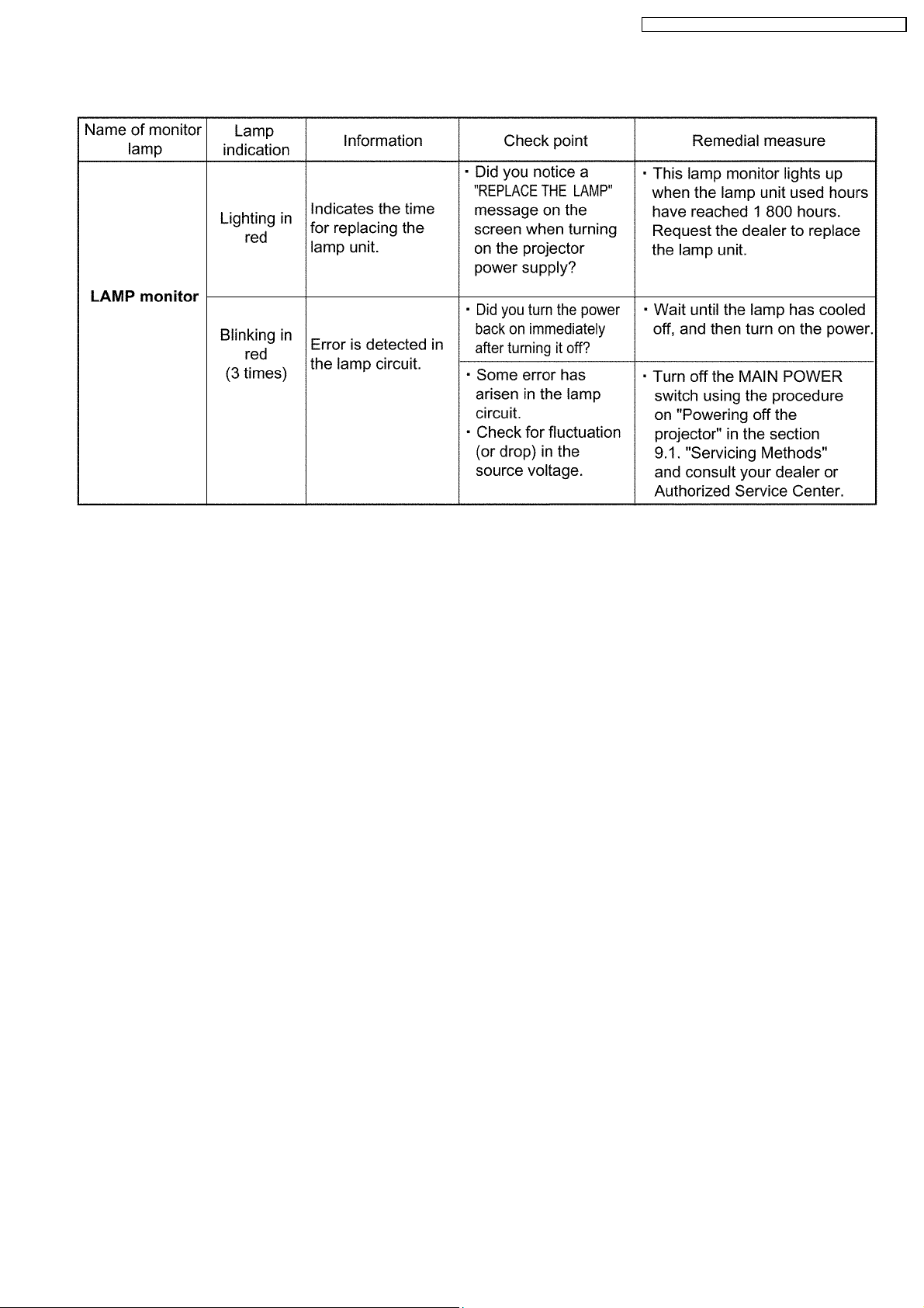
Error-code Contents Shutdown Error display condition Remarks
U11 Temperature warning (IN) Intake air temperature is the specific value or
U12 Temperature warning (OPT) Optical module temperature is the specific
U13 Temperature warning (OUT) Lamp surroundings temperature is the specific
U14 Low temperature warning (OPT) Optical module temperature is less than the
U21 Temperature error (IN) Intake air temperature is the specific value or
U22 Temperature error (OPT) Optical module temperature is the specific
U23 Temperature error (OUT) Lamp surroundings temperature is the specific
U24 Low temperature error (OPT) *1 Optical module temperature is less than 5°C.
U41 Lamp 1 operating time warning
U42 Lamp 2 operating time warning
U43 Lamp 3 operating time warning
U44 Lamp 4 operating time warning
U61 Lamp 1: 2 000 hour operating time
exceeded
U62 Lamp 2: 2 000 hour operating time
exceeded
U63 Lamp 3: 2 000 hour operating time
exceeded
U64 Lamp 4: 2 000 hour operating time
exceeded
higher.
value or higher.
value or higher.
specific value.
higher.
value or higher.
value or higher.
Lamp cumulative usage time is 1 800 hour or
longer.
*2
*2
Lamp cumulative usage time is 2 000 hour or
longer.
*2
*2
After turning on the power, the
shutdown processing is not
done for 2.5 minutes.
LAMP monitor lights in red.
After turning on the lamp, it will
turn off in 10 minutes. LAMP
monitor lights in red.
14
PT-D10000U / PT-D10000E / PT-DW10000U / PT-DW10000E
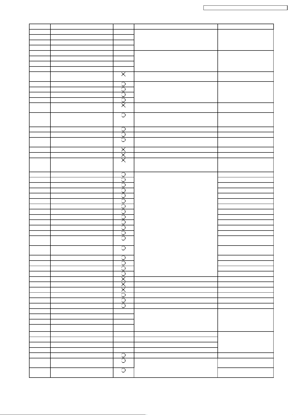
Error-code Contents Shutdown Error display condition Remarks
U51 Lamp 1 going out *2
U52 Lamp 2 going out *2
U53 Lamp 3 going out *2
Lamp goes out after turning on. LAMP monitor blinks 3 times in
red.
U54 Lamp 4 going out *2
U51 Lamp 1 lighting failure *2
U52 Lamp 2 lighting failure *2
U53 Lamp 3 lighting failure *2
Lamp ignition failure LAMP monitor blinks 3 times in
red.
U54 Lamp 4 lighting failure *2
U70 Air filter unit not installed Air filter unit is not installed. Confirms the i nstallation when
turning on the power.
U71 Lamp 1 not installed
U72 Lamp 2 not installed
U73 Lamp 3 not installed
Lamp is not installed (The lamp memory cannot
be read.)
LAMP monitor blinks 3 times in
red.
U74 Lamp 4 not installed
U81 AC power supply voltage drop
AC power supply voltage drops.
warning (less than 90 V)
U91 Lamp unit cover is not closed Lamp unit cover is not closed for 1 second or
longer.
If the cover is not closed when
turning on the power, it does
not turn on.
H11 Thermosensor disconnected (IN) Intake air thermosensor is disconnected.
H12 Thermosensor disconnected (OPT) Optical module thermosensor is disconnected.
H13 Thermosensor disconnected
(OUT)
Lamp surroundings thermosensor is
disconnected.
H18 Airflow sensor disconnect e d Airflow sensor is disconnected.
U04 Air filter is blocked The air filter accumulates dust.
H01 Internal clock battery replacement The date is before December 31, 2005 or after
January 1, 2036.
If this error occurs, the date is
reset on 00:00:00, January 1,
2006.
FE1 Fan error 1: P-UNIT FAN
Power unit fan
FE2 Fan error 2: LAMP1 FAN Lamp fan 1
FE3 Fan error 3: LAMP2 FAN Lamp fan 2
FE4 Fan error 4: LAMP3 FAN Lamp fan 3
FE5 Fan error 5: LAMP4 FAN Lamp fan 4
FE6 Fan error 6: BALLAST1 FAN Ballast fan 1
FE7 Fan error 7: BALLAST3 FAN Ballast fan 3
FE8 Fan error 8: RADIATOR FAN Radiator fan
The fan stops for 5 seconds or longer.
FE9 Fan error 9: EXAUST FAN C Exhaust f an (C)
FF0 Fan e rror 10: EXAUST FAN L Exhaust fan (L)
FF1 Fan e rror 11: EXAUST FAN R Exhaust fan (R)
FF2 Fan error 12: R-DMD FAN R-DMD fan
FF3 Fan (Module) error 13: G-LIQUID
Liquid cooling pump (G)
COOLING
FF4 Fan (Module) error 14: B-LIQUID
Liquid cooling pump (B)
COOLING
FF5 Fan e rror 15: C-PRISM FAN Color prism fan
FF6 Fan error 16: L-PRISM FAN Lamp prism fan
FF7 Fan error 17: BALLAST2 FAN Ballast fan 2
FF8 Fan error 18: BALLAST4 FAN Ballast fan 4
F11 Shutter error Shutter error
F12 Dynamic iris error Dynamic iris error
F13 Air filter unit error Air filter cleaning processing time-out
F21 2.5 V DC error 2.5 V DC error
F22 3.3 V DC error 3.3 V DC error
F23 5.0 V DC error 5.0 V DC error
F41 Lamp 1 memory error *2
F42 Lamp 2 memory error *2
F43 Lamp 3 memory error *2
Lamp EEPROM is abnormal. LAMP monitor blinks 3 times in
red.
F44 Lamp 4 memory error *2
FP1 Lamp 1 PFC error *2 Lamp 1 PFC error
FP2 Lamp 2 PFC error *2 Lamp 2 PFC error
FP3 Lamp 3 PFC error *2 Lamp 3 PFC error
LAMP monitor blinks 3 times in
red.
FP4 Lamp 4 PFC error *2 Lamp 4 PFC error
F91 FPGA1 configuration error A-P.C.Board is abnormal.
F92 FPGA2 (SXGA+) configuration
FH-Module is abnormal. for PT-D10000*
error
F92 FPGA2 (FULL-HD) configuration
for PT-DW10000*
error
15

PT-D10000U / PT-D10000E / PT-DW10000U / PT-DW10000E
Error-code Contents Shutdown Error display condition Remarks
F93 Flash ROM error The circuit around CPU on A-P.C.Board is
F94 RAM error
F95 FPGA expansion error
F96 Lens shift error The circuit for lens position detection is
abnormal.
abnormal.
Explanatory notes of shutdown column
Shutdown occurs.
Shutdown does not occur.
*1 Shutdown occurs only when starting. (Shutdown does not occur even if the temperature becomes less than 5°C during normal
operating.)
*2 Shutdown occurs when all lamps cannot be lit.
16
PT-D10000U / PT-D10000E / PT-DW10000U / PT-DW10000E
6 Using the Serial Terminals
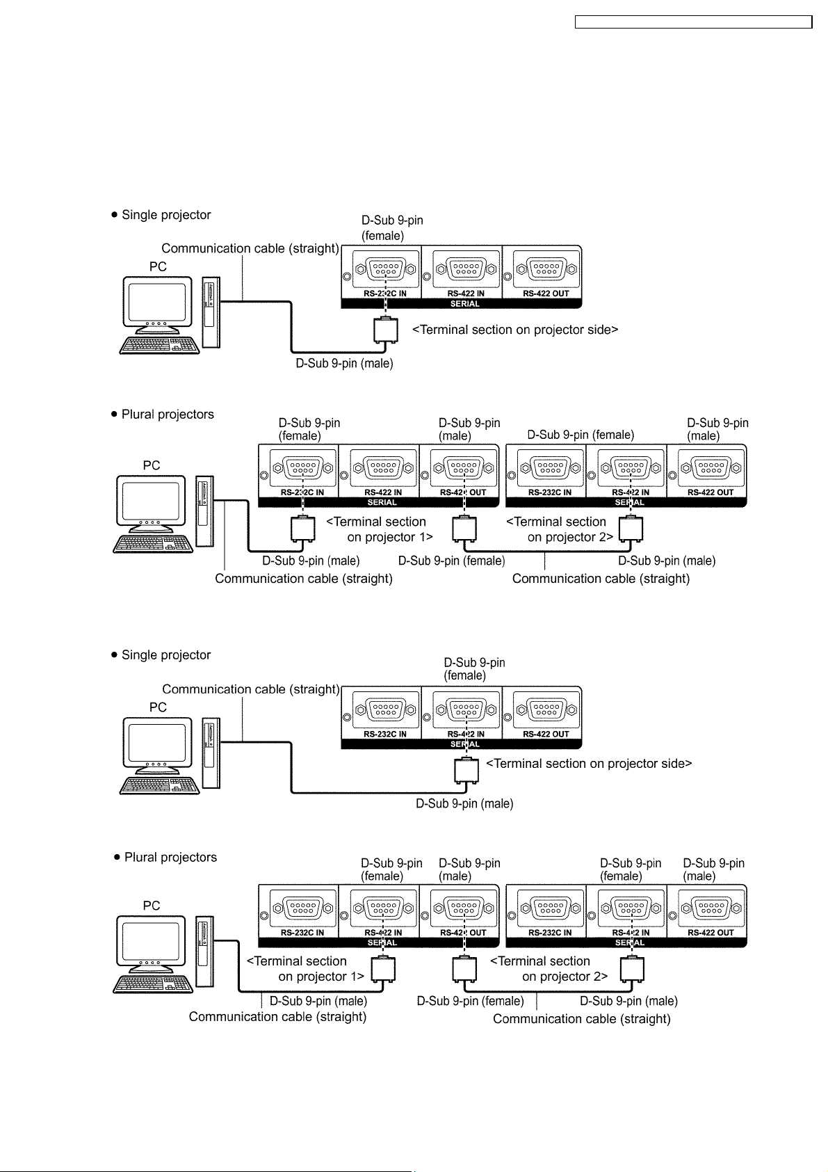
THe main unit is equipped with SERIAL terminals located in its terminal section on the side, and this terminal is compliant with RS232C/RS-422. Also a serial output terminal is provided to enable plural projector control.
6.1. Example of Connection
RS-232C
RS-422
17
PT-D10000U / PT-D10000E / PT-DW10000U / PT-DW10000E
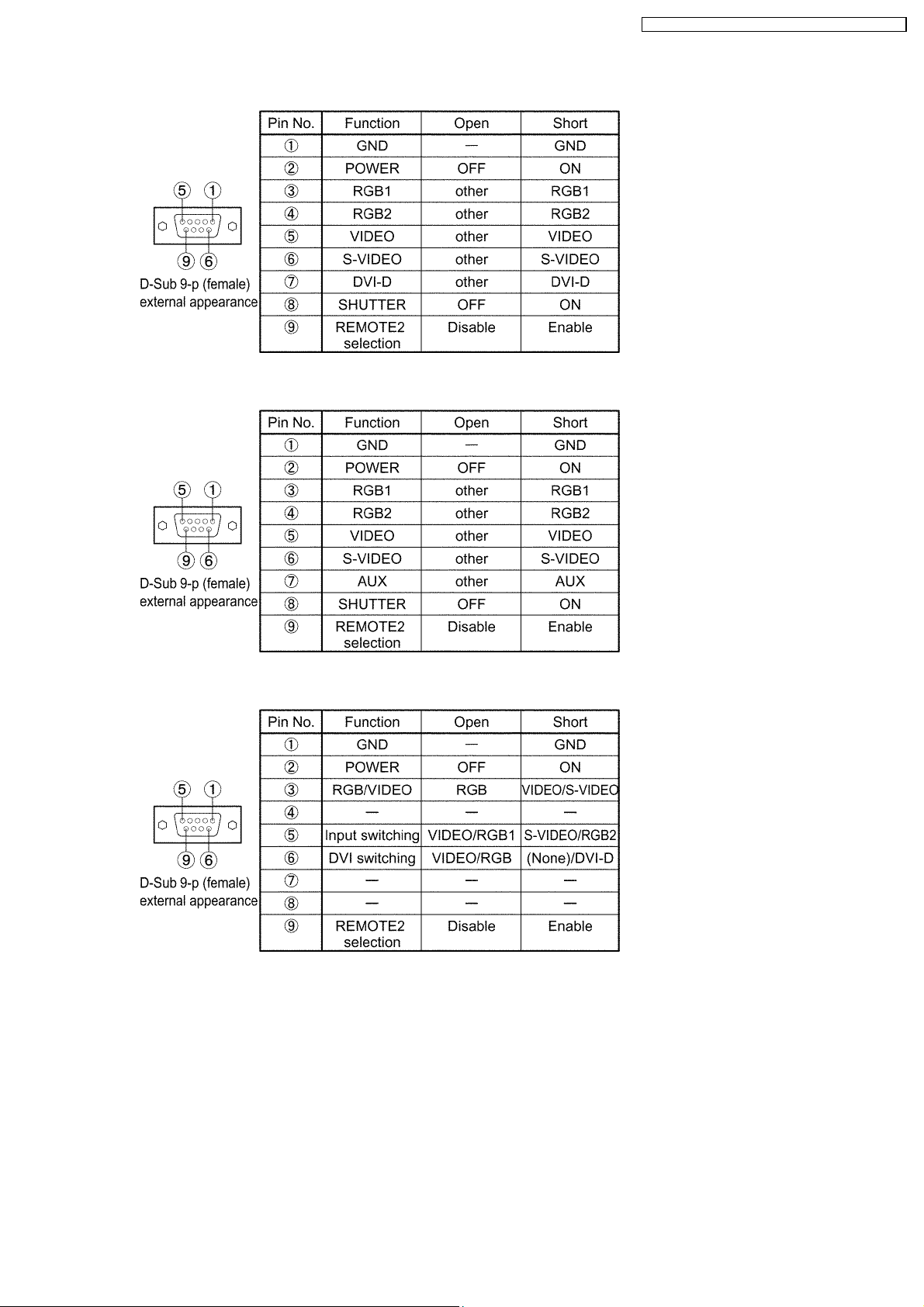
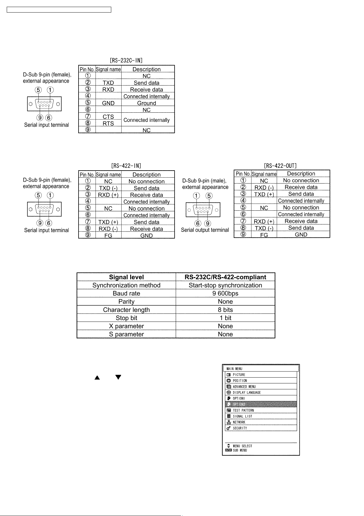
6.2. Pin Assignments and Signal Names
RS-232C
RS-422
6.3. Communication Conditions (Factory Setting)
6.4. Procedure of Communication Condition Settings
(1) Press the MENU button.
The MAIN MENU screen will be displayed.
(2) Select OPTION2 using the or buttons.
18
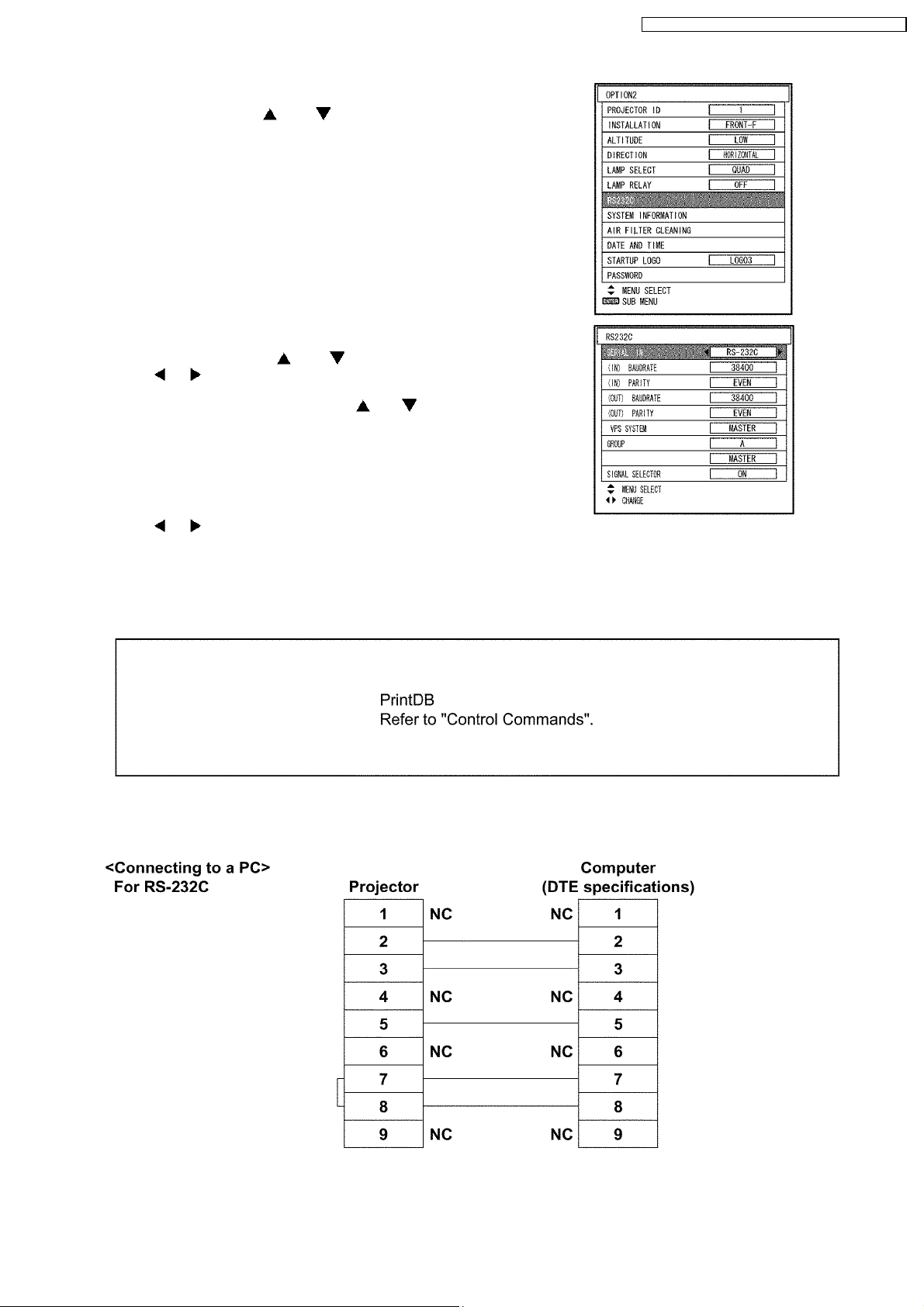
(3) Press the ENTER button.
The OPTION2 screen will be displayed.
(4) Select RS232C using the or buttons.
(5) Press the ENTER button.
The RS-232C screen will be displayed.
(6) Select SERIAL IN using the or buttons.
(7) Press buttons to switch SERIAL IN.
RS-232C and RS-422 will switch each time the button is pressed.
(8) Select communication conditions using the or buttons.
PT-D10000U / PT-D10000E / PT-DW10000U / PT-DW10000E
(9) Press buttons to confirm the setting.
(10) Press the MENU button 3 times.
The on-screen indications disappear, and the system returns to the
normal screen.
6.5. Control commands
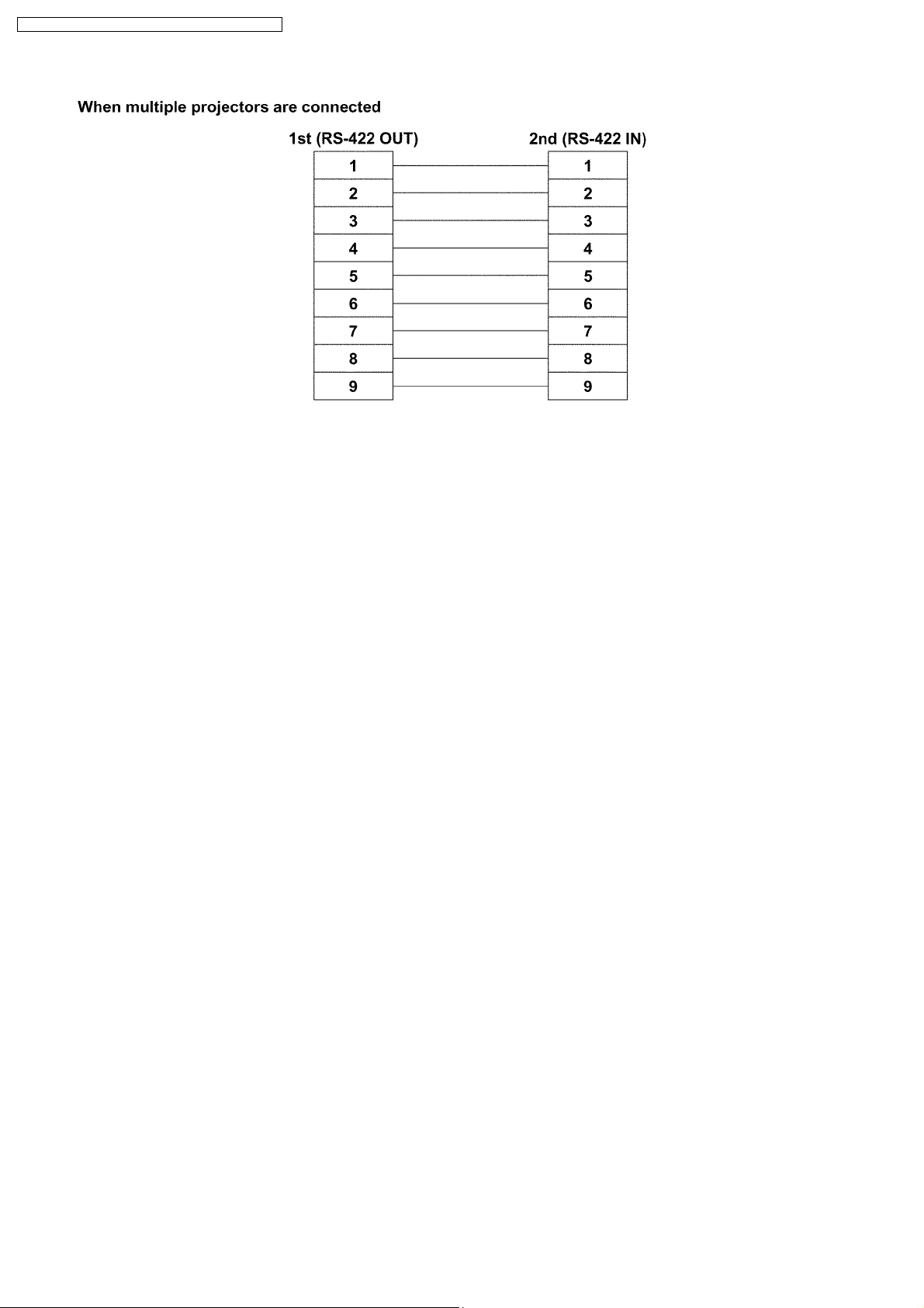
6.6. Cable specifications
19
PT-D10000U / PT-D10000E / PT-DW10000U / PT-DW10000E
Note
To connect the computer to the SERIAL terminal, prepare an adequate communication cable that fits to your personal
computer.
20
PT-D10000U / PT-D10000E / PT-DW10000U / PT-DW10000E
7 Using a Wired Remote Control
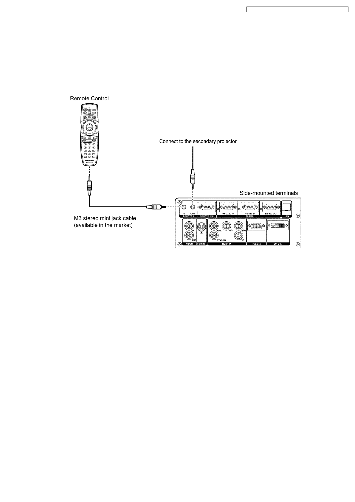
7.1. Connection Example
When multiple main units are connected as part of the system, connect to units with a M3 stereo mini jack cable (sold separately)
to simultaneously control multiple main units with a single remote control through the REMOTE1 IN/OUT terminal. It is effective to
use the wired remote control in the environment in which an obstacle stands in the light path or where devices are susceptible to
outside light.
· Use a two-wire shielded cable with a length of 15 m or less. If the length of the cable exceeds 15 m, the shielding of the cable
may not be sufficient and the remote control may not work.
7.2. Setting Projector ID Number to Remote Control
Every projector has its ID number and the ID number of the controlling projector must be set to the remote control in advance so
that the user can operate the remote control. The ID number of the projector is set to “ALL” on shipping, and use the ID ALL button
of the remote control when using only a single projector.
Procedure of ID setting
Press ID SET, and then within 5 seconds, press the two numeric (0-9) buttons which correspond to the ID number that has been
set for the projector.
· The main unit has its ID number (1-64 or ALL), and set to remote control when the ID number is 1-9 as 01-09. When the
ID number is "ALL", set it with the ID ALL button of the remote control unit.
· Do not press the ID SET button accidentally or carelessly because the ID number on the Remote Control can be set even
when no projector is around.
· If you do not enter the two-digit ID number within 5 seconds after the ID SET button has been pressed, the ID number will
remain at the number that was set before the ID SET button was pressed.
· Your specified ID number is stored in the remote control unit unless another one is specified later. However, the stored ID
will be erased if the batteries of the remote control are left exhausted. When the batteries are replaced, set the same ID
number again.
21
PT-D10000U / PT-D10000E / PT-DW10000U / PT-DW10000E
8 Support for Service
8.1. Supporting Methods
We will support according to the following methods.
Supporting methods Applied parts
Replaced by module or block
Replaced at the manufacturing
department
Replaced by discrete components Other components
K-Module
PC-Module
PF-Module
NN-Module
FH-Module
B/Q-Module (For specified components, supplies them discretely.)
CL-P.C.Board
J-P.C.Board
J2-P.C.Board
J3-P.C.Board
R-P.C.Board
R2-P.C.Board
R3-P.C.Board
L1-P.C.Board
L2-P.C.Board
L3-P.C.Board
L4-P.C.Board
H-P.C.Board
SL-P.C.Board
LH-P.C.Board
LV-P.C.Board
Optical block (Analysis block, Color prism block)
Analysis mirror
Lens mount
Liquid cooling unit
DMD™ block
8.2. Note for Replacement of A-P.C.Board
Transfer the data of the original A-P.C.Board to the new A-P.C.Board using the adjustment software and a personal computer. (If
you cannot transfer the data, remove IC2611, IC2618 and IC2619 from the original board and mount them on the new board.)
* Consult your dealer or Authorized Service Center for the adjustment software.
8.3. Replacement of the lithium battery on the A-P.C.Board
If the lithium battery will be empty, replace it with a new one (CR2032 or equivalent).
Cautions
· Explosion may occur if replacing the battery with an incorrect one.
· Dispose of used batteries according to the instructions.
9 Cautions for Service
9.1. Servicing Methods
· Never unplug the power cord from the outlet, open the circuit breaker, or perform other procedures to cut off the power line
during the operation of any cooling fan.
· Be sure to unplug the power cord from the power outlet before servicing.
Powering off the projector
1. Press the POWER STANDBY "
2. Select "OK" with
The projection of the image stops, and power indicator lamp of the main unit lights up orange. (The cooling fan keeps
running.)
3. Wait until the power indicator lamp of the main unit turns to red (i.e., until the cooling fan stops).
4. Press the "
or button and press the ENTER button. (or press the POWER STANDBY " " button again.)
" marked side of the MAIN POWER switch to remove all power from the projector.
" button.
22
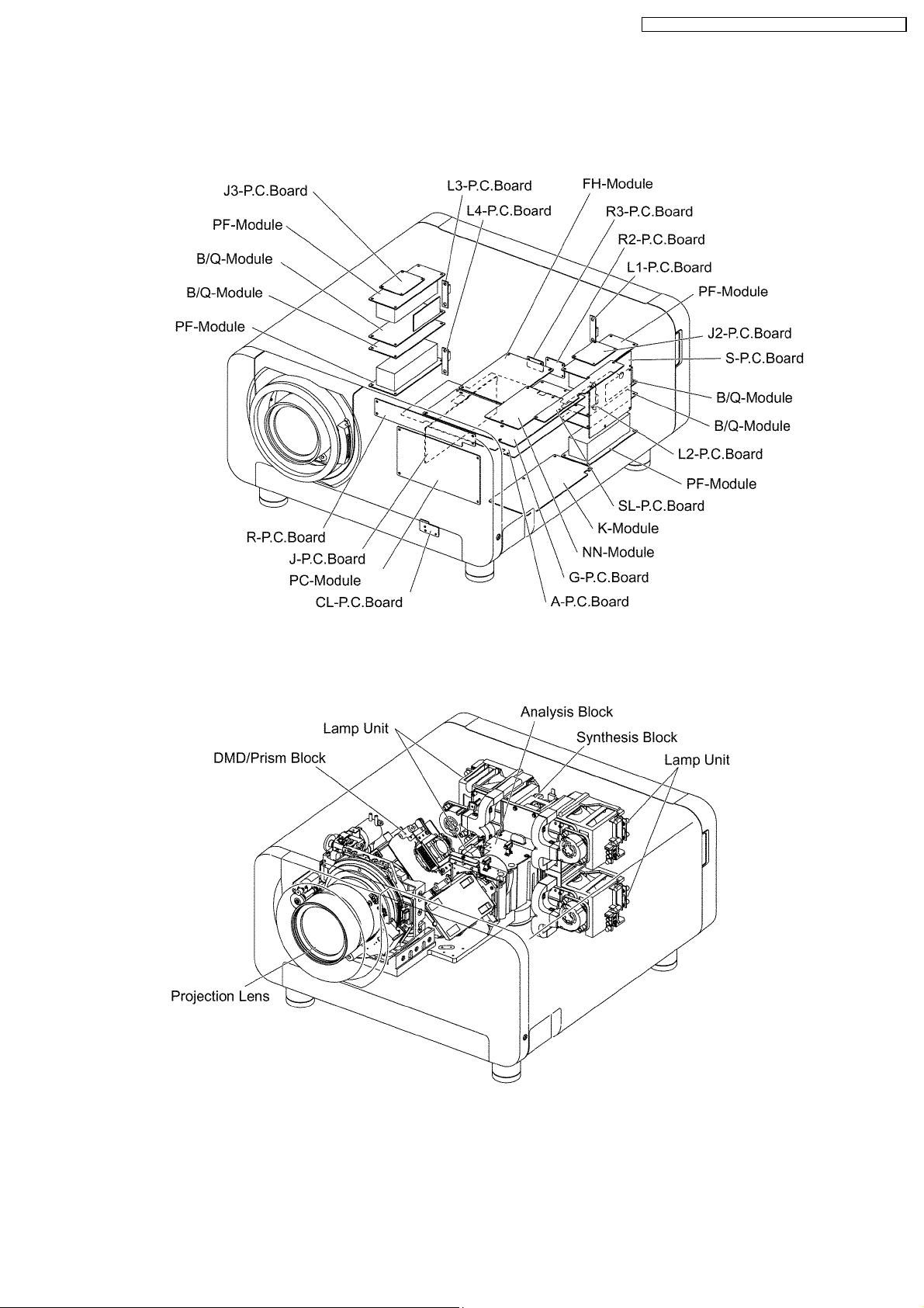
10 Parts Location
10.1. Electrical Parts Location
PT-D10000U / PT-D10000E / PT-DW10000U / PT-DW10000E
10.2. Electromechanical Parts Location
23
PT-D10000U / PT-D10000E / PT-DW10000U / PT-DW10000E
11 Replacement of Lamp Unit
Cautions
· Wait until the lamp is cooled sufficiently before replacing the lamp unit.
· Make sure that all four lamp units are installed.
· Replace of the lamp unit should be carried out by a qualified technician.
11.1. Precautions on Lamp Unit Replacement
Remove the power plug and confirm that the surroundings of the lamp unit have cooled off.
· Be careful when handling a light source lamp. The lamp unit has high internal pressure. If improperly handled, explosion might
result.
· A used lamp unit may burst if it is handled violently.
For disposition of used lamps, request an industrial waste disposal contractor.
· If you continue to use a lamp after the replacement time, the lamp may break.
· Philips screwdriver is necessary when replacing a lamp unit.
Take care not to slip your hand when using a screwdriver.
Attention
· A lamp unit is an optional part. Contact the dealer.
Replacement lamp unit model No.: ET-LAD10000 (single bulb), ET-LAD1000F (4 bulbs)
Rating: 250 W
· Other lamps than specified above cannot be used. Be sure to use the specified lamp.
11.2. Timing of Lamp Unit Replacement
The lamp used for the light source has its due life. The life of light source lamp used in the main unit is 2 000 hours. However, it
may happen that the lamp becomes dead (will not light) by the time of 2 000 hours depending on the characteristics of individual
lamps and working conditions (lamps may reduce their life affected by the times of lighting and the intervals between previous
lighting and next lighting). Therefore, it is strongly recommended for the user to keep a spare bulb. If a lamp unit has not been
replaced after 2 000 hours of operation have elapsed, the lamp will turn off automatically. when the operating time for all of the
lamps reaches 2 000 hours or more, the power will turn off automatically approxmately 10 minutes after it is turned on, and the
projector will switch to standby mode.
24
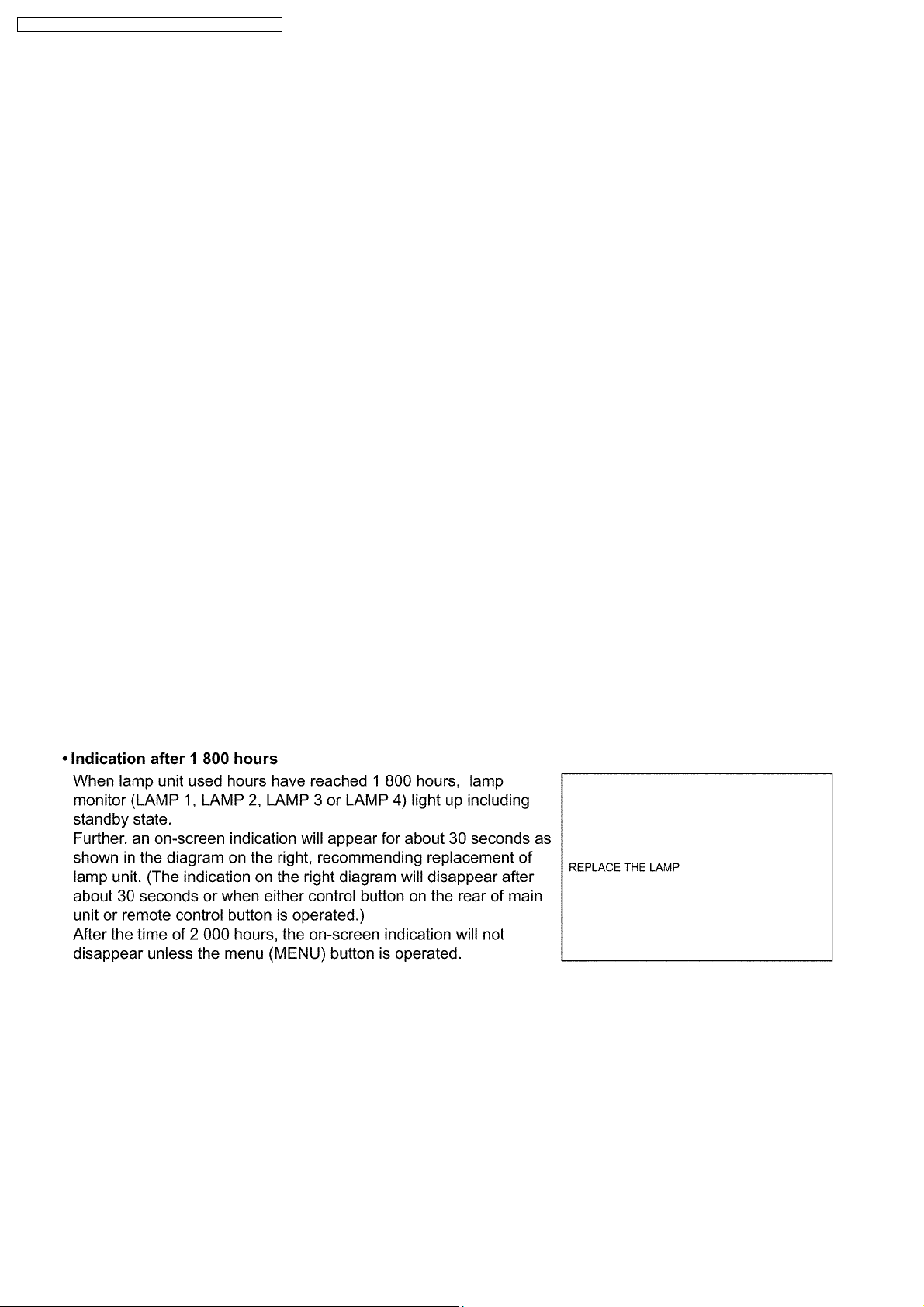
11.3. Indication of Lamp Monitor
PT-D10000U / PT-D10000E / PT-DW10000U / PT-DW10000E
25
PT-D10000U / PT-D10000E / PT-DW10000U / PT-DW10000E
12 Disassembly Instructions
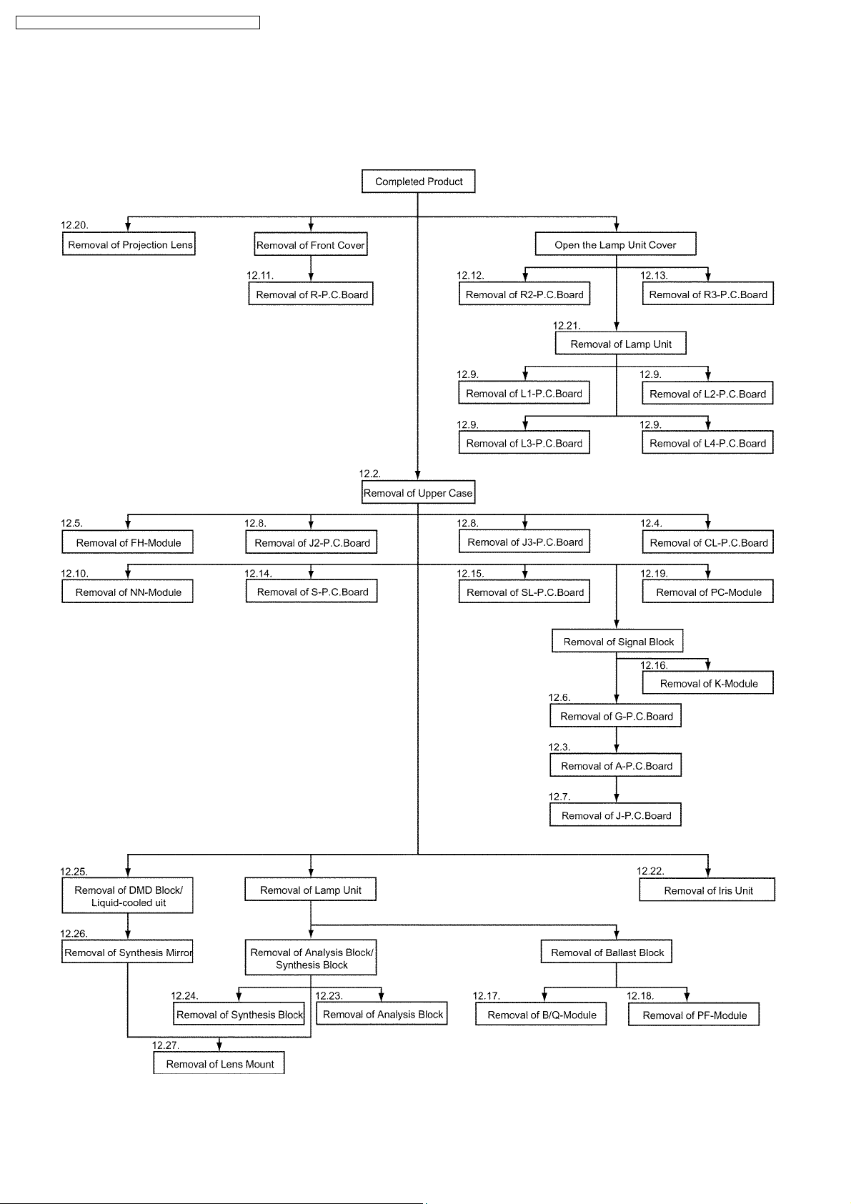
12.1. Flowchart for Disassembly
To assemble, reverse the disassembly procedures.
26
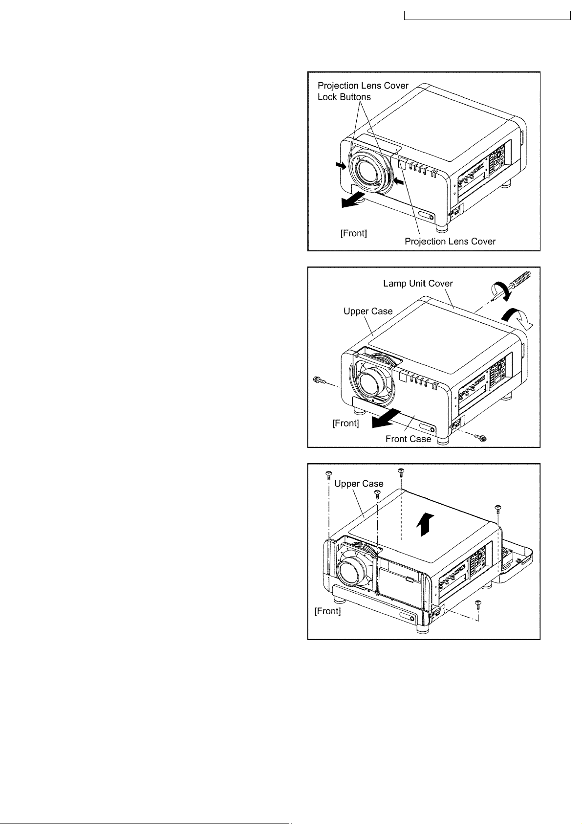
12.2. Removal of Upper Case
(1) While pressing the projection lens cover lock buttons, pull the
cover forward to remove it.
(2) Unscrew the 2 screws and remove the front case.
(3) Loosen the 1 screw until it idles and open the lamp unit cover.
PT-D10000U / PT-D10000E / PT-DW10000U / PT-DW10000E
(4) Unscrew the 5 screws and remove the upper case.
27
PT-D10000U / PT-D10000E / PT-DW10000U / PT-DW10000E
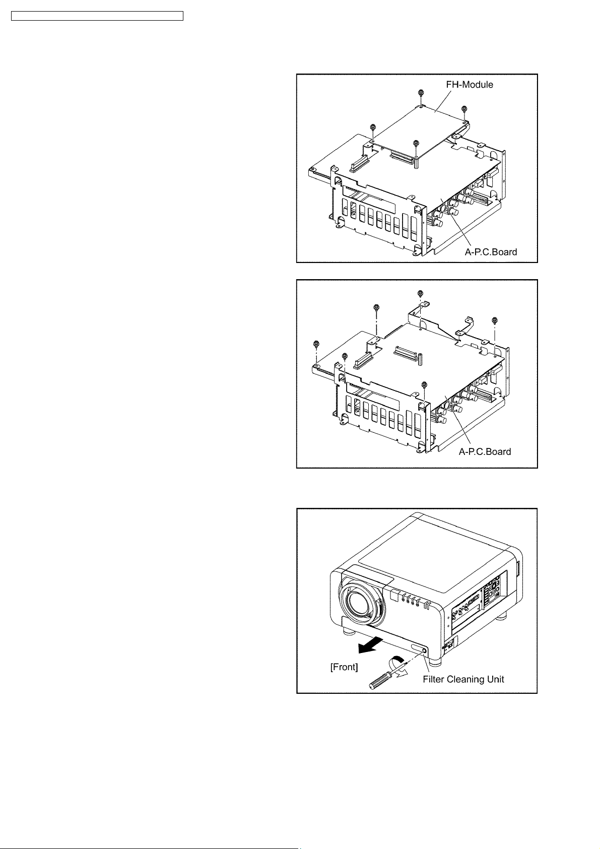
12.3. Removal of A-P.C.Board
(1) Remove the G-P.C.Board according to the section 12.6.
"Removal of G-P.C.Board".
(2) Unscrew the 4 screws and remove the FH-Module.
Note:
· The FH-Module is connected onto the A-P.C.Board with
the connector. Work caref ully when removing it.
(3) Unscrew the 6 screws and remove the A-P.C.Board.
12.4. Removal of CL-P.C.Board
(1) Loosen the 1 screw until it idles and take the filter cleaning unit
out.
28
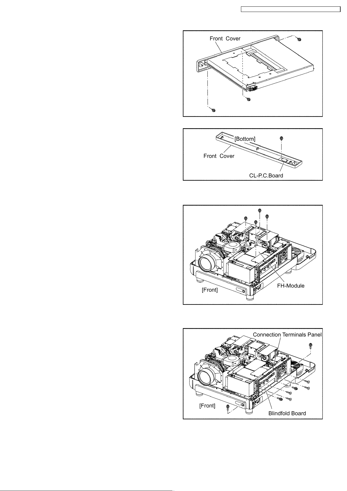
(2) Unscrew the 3 screws and remove the front cover.
(3) Unscrew the 1 screw and remove the CL-P.C.Board.
PT-D10000U / PT-D10000E / PT-DW10000U / PT-DW10000E
12.5. Removal of FH-Module
(1) Remove the upper case according to the section 12.2. "Removal
of Upper Case".
(2) Unscrew the 4 screws and remove the FH-Module.
12.6. Removal of G-P.C.Board
(1) Remove the upper case according to the section 12.2. "Removal
of Upper Case".
(2) Unscrew the 2 screws and remove the blindfold board.
(3) Unscrew the 6 screws and remove the connection terminals
panel with S-P.C.Board and SL-P.C.Board.
29
PT-D10000U / PT-D10000E / PT-DW10000U / PT-DW10000E
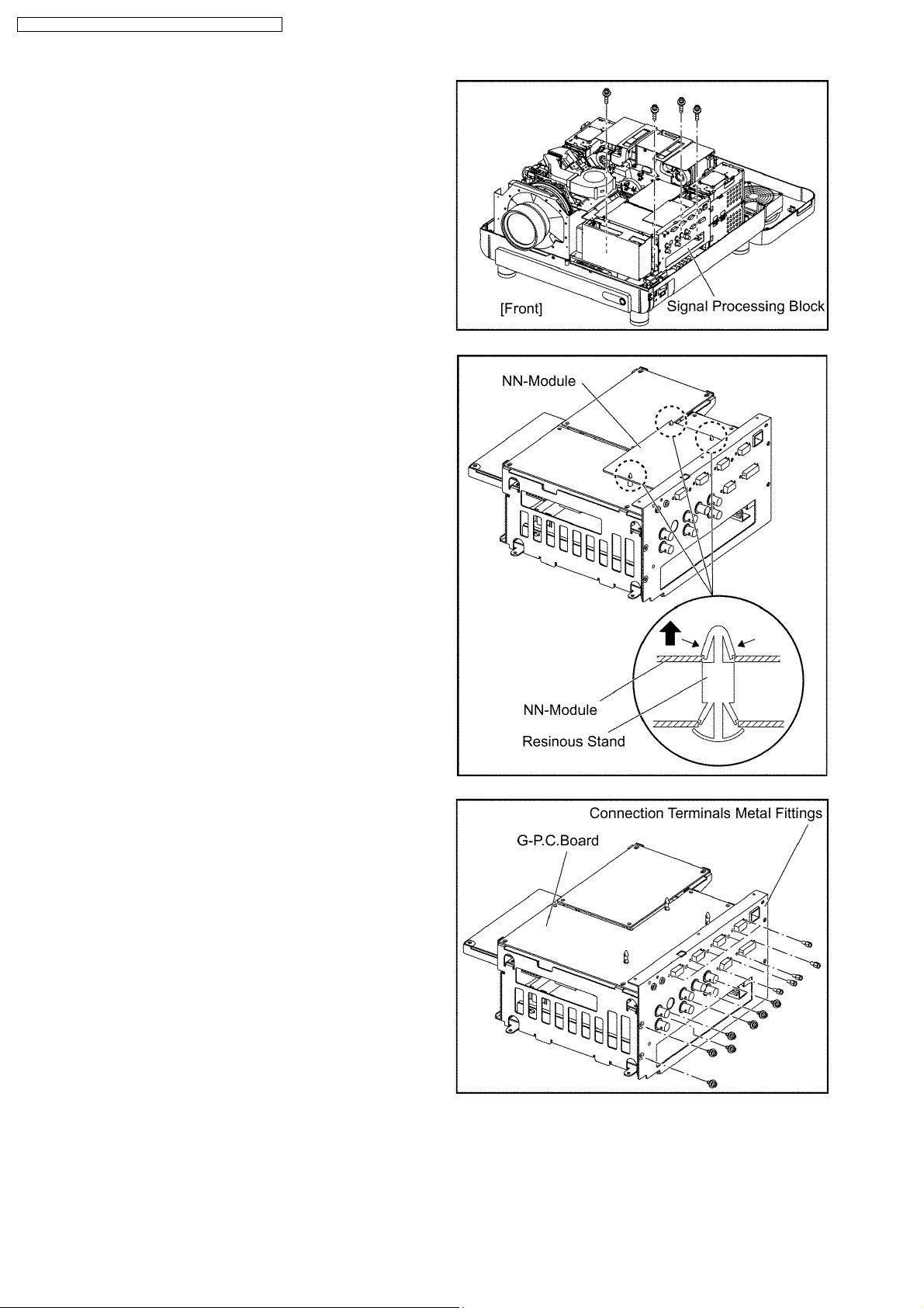
(4) Unscrew the 4 screws and remove the signal processing block.
(5) While pressing to shut each hook of the 3 resinous stands,
remove the NN-Module.
(6) Unscrew the 19 screws and remove the connection terminals
metal fittings.
30
 Loading...