

ORDER NO. MTNC000524A1
B2
Service Manual
Color Video Projection Syste m
d
e
i
f
i
S
m
i
l
p
Simplified Manual
(P4C)
Panasonic
Models
PT-56SX30B FP816
PT-56SX30CB FP816
PT-56D30B GP816
PT-56D30CB GP816
Note: Appearance may
vary depending on model
characteristics.
This Simplified Service Manual is issued to add listed models to the Main Service Manual order No. MTNC000211C1.
(PT-61D30B/CB) A full set of schematics, disassembly procedures, and a complete parts list are included in this
Simplified Manu al. Please file and us e this Simplifi ed Service Manu al together with Ma in Service Ma nual, order No .
MTNC000211C1. (PT-61D30B/CB)
“WARNING! This Service Manu al is desi gned for ex perienced repai r technicia ns only and is not des igned for us e by the g eneral publi c.
It does not contain warnings or cautions to advise non-technical individuals of potential dangers in attempting to service a product.
Products powered by electricity should be se rviced or repaired only by experie nced profes sional tec hnicians . Any attempt to
service or repair the product or products dealt with in this Service Manual by anyone else could result in serious injury or death.”
Chassis
The service technician is required to read and follow the “Safety Precautions” and “Important Safety Notice” in the Main Manual.
Copyright 2000 by M atsus hita Electri c Corpo ration of
America. All rights reserved. Unauthorized copying
®
and distribution is a violation of law.
Important Safety Notice
Special components are used in this projecti on television which a re important for safety. These components are
identified on the schematic diagram by the symbol and printed in BOLD TYPE on the replacement part list. It is
essential that these critic al parts are replac ed with th e manufact urer ’s speci fied repla cement part to prevent x -ray
radiation, shock, fire or other hazards. Do not modify the original design without the manufacturer’s permission.
Safety Precautions
General Guidelines
An
isolation transformer
during the servicing of a PTV whose chassis is not
isolated from AC power line. Use a transformer of
adequate power rating as this protects the technician
from accidents resulting in personal injury from
electrical shocks. It will also protect the PTV from being
damaged by accidental shorting that may occur
during servicing.
When servicing, observe the original lead dress,
especially in the high voltage circuit. Replace all
damaged parts (also parts that show signs of
overheating.)
Always replace protective devices, such as
fishpaper, isolation resistors and capacitors, and
shields after servicing the PTV. Use only
manufacturer ’s recommended rating for fuses, cir cuits
breakers, etc.
High potentials, as high as 32kV, are present when this
PTV is operating. Operation of the PTV without the rear
cover introduc es danger for el ectrical sho ck. Servicin g
should not be performed by anyone who is not
thoroughly familiar with the necessary precautions
when servicing high-voltage equipment.
Extreme care should be prac ticed when handling the
picture tube
due to atmospheric pres s ure. (1 4.7 lb s. per sq . i n.). Do
not nick or scratch the glass or subject it to any undu e
pressure. When handling, use safety goggles and
heavy gloves for protection. Discharge the picture
tube by shorting the anode to chassis ground (not to
the cabinet or to other mounting hardware). When
discharging connect cold ground (i.e. DAG ground
lead) to the anode with a well insulated wire or use a
grounding probe.
. Rough handling may caus e it to implod e
should always be used
X-ray Precautions
The front area (between the projection tube and the
lens) is enclosed by a metal box to ensure positive
safety during normal and abnormal conditions when
checking and repairing. To fully ensure safety, the
following precautions must be observed.
1. Do not remove the lens or metal box.
2. Make sure to turn the power OFF when the le ns is
removed or when checkin g the cleanliness of the
lens.
3. Do not remove the lens or metal box to check the
projection tube for oper ati on by watc hi ng i t di rec tly.
Use a mirror or paper to view the image.
Before returning a serv iced PTV to the owner, the
service technician must thoroughly test the unit to
ensure that is completely safe to operate. Do not use a
line isolation transformer when testing.
Leakage Current Cold Check
Unplug the AC cord and connect a jumper between the
two plug prongs. Press the POWER switch ON.
Measure the re si stance betw e e n th e j um p ere d AC pl ug
and expose metallic parts such as screw heads,
Service Manual
antenna terminals, control shafts, etc. If the exposed
metallic part has a return path to the chassis, the
reading should be between 240kΩ and 5.2MΩ. If the
exposed metallic part does not have a return path to
the chassis, the reading should be infinite.
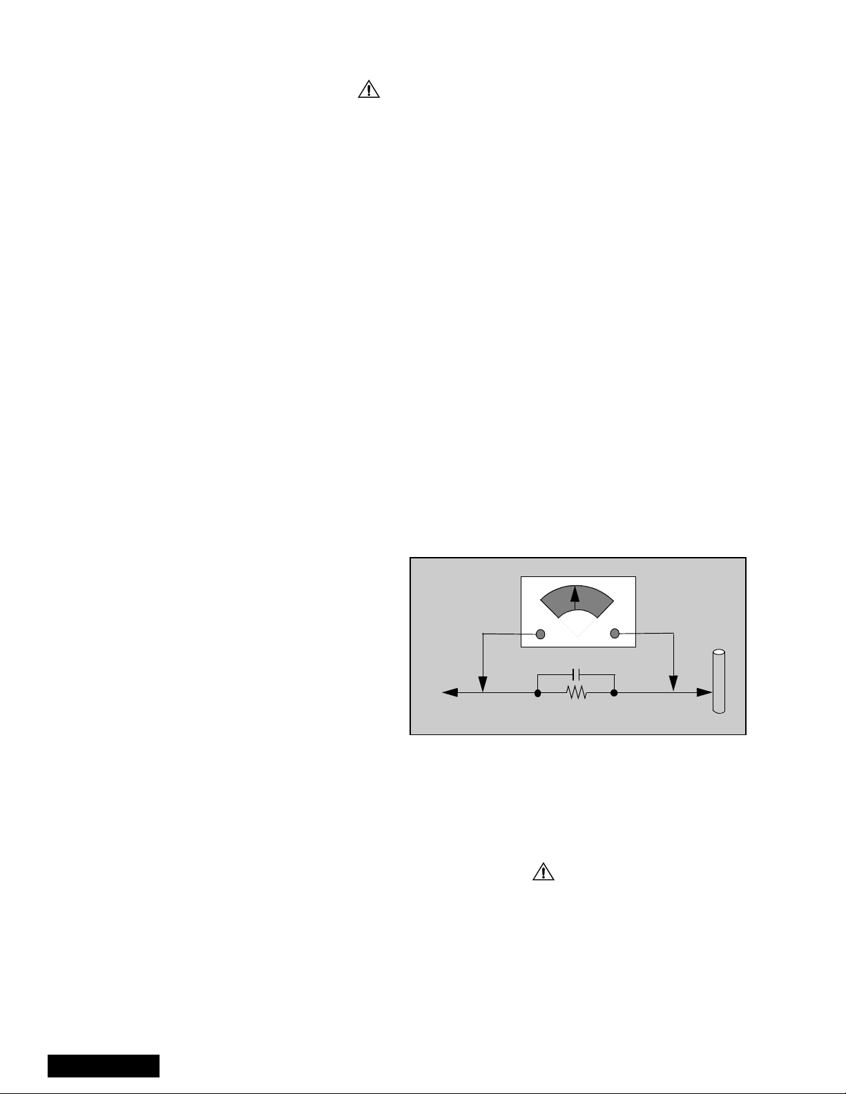
Leakage Current Hot Check (See Figure 1)
Plug the AC cord directly into the AC outlet. Do not use
an isolation transformer during the check.
Connect a 1.5kΩ 10 watt resistor in parallel with a
0.15µF capacitor between and exposed metallic part
and ground. Use earth ground, for example a
water pipe.
Using a DVM with a 1000 ohms/volt sensitivity or
higher, measure the AC potential across the resistor.
Repeat the procedure and measure the voltage
present with all other expose metallic parts.
Verify any potential does not exceed 0.7 5 volt RMS. A
leakage current tester (such a Simpson Model 229,
Sencore Model PR57 or equivalent) may be used in
the above procedure, in which case any current
measure must not exceed 1/2 milliamp. If any
measurement is out of the specified limits, there is a
possibility of a shock hazard and the PTV must be
repaired and rechecked before it is returned to
the customer.
AC VOLTMETER
COLD
WATER
PIPE
(GROUND)
0.15µF
TO INSTRUMENT’S
EXPOSED METAL
PARTS
Figure 1. Hot Check Circuit
1500Ω,10W
Insulation Test
Connect an insulation tester between an exposed
metallic part and AC line.
Apply 1080VAC/60Hz for 1 second. Confirm that the
current measurement is 0.5mA ~ 2.0mA. Repeat test
with other metallic exposed parts.
X-ray Radiation
WARNING: The potential source of X-ray radiation in the
PTV is in the hig h vo ltage section and the pict ure t ube .
Note: It is important to use an accurate, calibrated
high voltage meter.
Set brightness, picture, sharpness and color
controls to Minimum. Apply a all black video signal.
Measure the High Voltage. The high should be 31.5kV
±1.0kV. If the upper limit is out of tolerance, immediate
service and correction is required to insure safe
operation and to prevent the possibility of premature
component failure.
- 2 -
Important Safety Tests
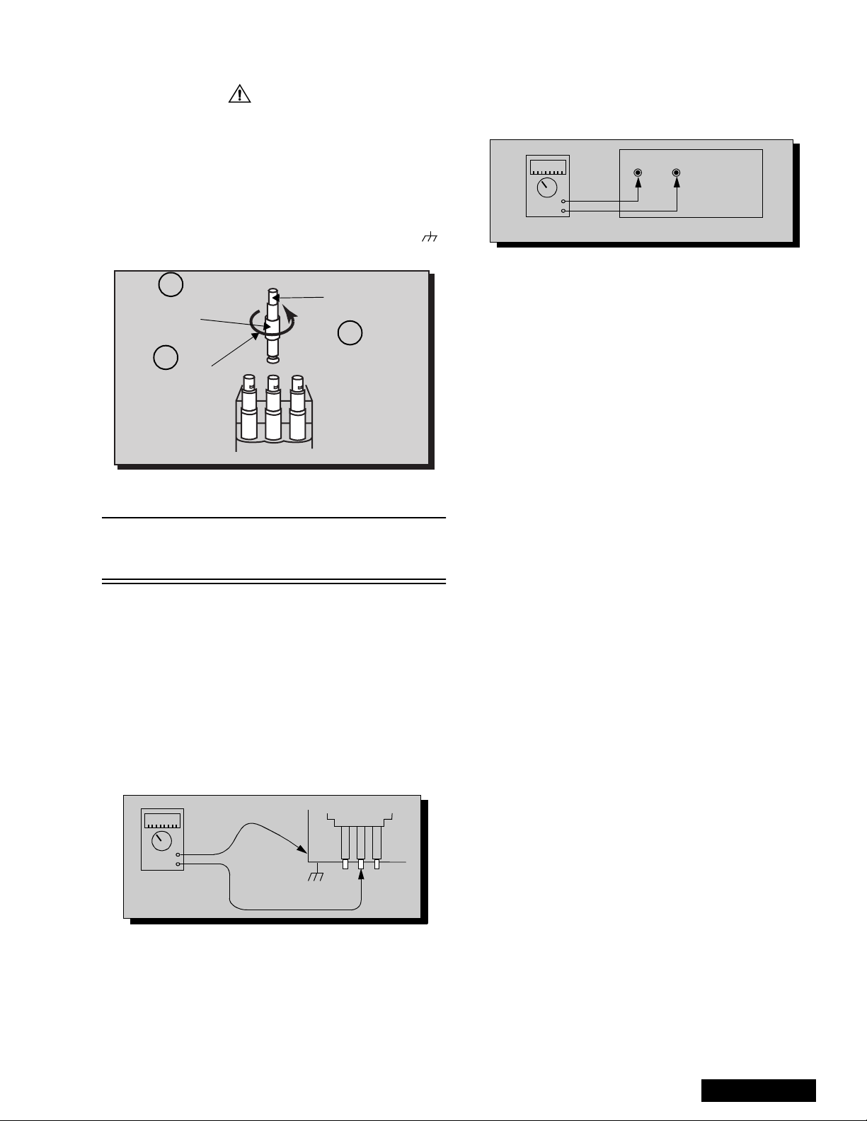
Measuring H.V.
The anode caps are cemented to the CRTs. To gain
access for high v oltage measurement, remove the red
CRT’s anode lead from the flyback transforme r (FBT)
distributor. Grasp the anode lead protective cap at its
bottom and squeeze it against the locking cap body
inside. Rotate 1/4 turn coun ter clockwise and pull the
anode lead sleeve out of the FBT distributor. Connect a
high voltage lead (+) from y our H.V. meter to the FBT
distributor, and the common (-) to cold ground ( ).
(See Figure 2).
1
Grasp protective
Anode lead
rubber cap
3
2
Squeeze & rotate
Discharge to
CRT Chassis
cap counterclockwise
to remove
FBT Distributor
Figure 2. Removal of FBT leads
Note: Reinsert the anode lead into the FBT
distributor until it is tightly and fully seated.
T urn the locking cap clockwise to lock in place.
(EHT) Protector Operation Check
With the cabinet ba ck removed, apply a n ominal 120V
AC to the PTV.
Over Voltage Test
Preparation:
1. Turn PTV “OFF”
2. Connect an NTSC signal generator to the
antenna terminal.
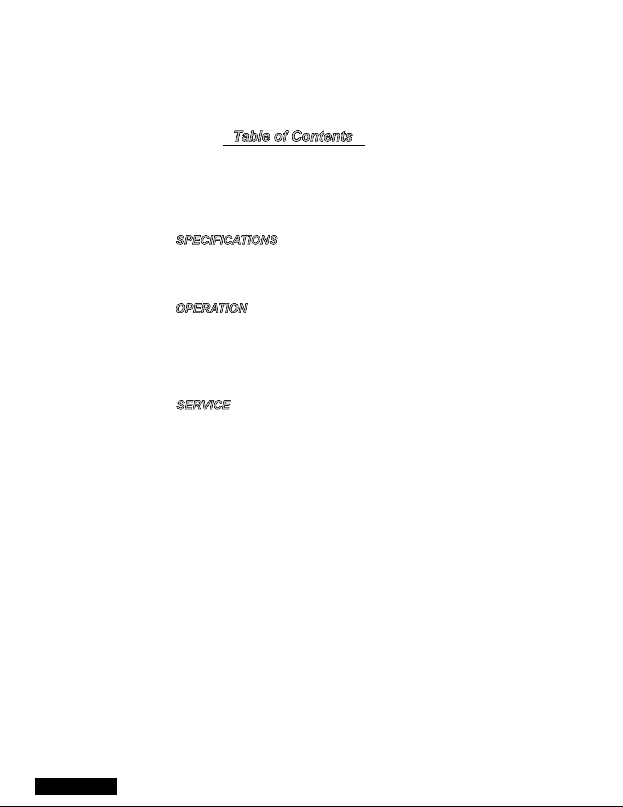
3. Connect DVM (+) TPD4 and ( -) TPD5 on D-Boa rd.
(See Figure 3)
4. Connect a H.V. meter (static type, class 0.1 ) with
high voltage leads to high voltage distributor
on FBT. (See Figure 4)
TPD5 TPD4
-
+
D-Board
DVM
Figure 4. DVM connected to D-Board.
5. Connect the 8 ~ 15 V DC variable power s upply to
(+) TPB10 and (-) TPBGND, on B-Board.
Procedures:
1. Apply a monoscope pattern.
2. Adjust the Picture or Brightness controls so that the
DVM reads 17.5 volts ± 0.5 volts.
3. Increase the variable po wer supply until set turns
off. The set should turn off at 17.5 volts ± 0.5 volts
(DVM) and high voltage less than 35.5kV.
4. If the DVM reading is other than 17.5volt (± 0.5
volts), repeat steps 2 and 3.
5. Turn off the variable supply and confirm that the set
will turn on with the Remote Control.
CRT Protect Circuit
This circuit blanks the CRT in the event that there is a
loss of vertical sweep. The circuit is not adjustable;
however the circuit should be checked each time
service is performed.
To check circuit:
1. Turn the PTV On an select an active channel.
2. Adjust Brightnes s and Picture control s for a visible
picture.
3. On D-Board momentarily connect a shor t-jumper
from TPD2 to TPDGND. The CRT shou ld blank. If
this does not occur, repair must be performed
before returning PTV to customer.
4. Remove short-jumper.
-
+
H.V. METER
FBT Distributor
CRT
CHASSIS
Figure 3. Measuring H.V.
- 3 -
Service Manual
Important Safety Notice . . . . . . . . . . . . . . . . . . .2
Safety Precautions . . . . . . . . . . . . . . . . . .2
Important Safety Tests . . . . . . . . . . . . . . .3
Service Notes. . . . . . . . . . . . . . . . . . . . . . . . . . . .5
PTV Feature Table. . . . . . . . . . . . . . . . . . . . . . . .7
PCB Designation . . . . . . . . . . . . . . . . . . . . . . . . .8
PTV - Location of Controls
PTV Front Control Panel . . . . . . . . . . . . .9
Remote - Location of Controls
EUR511151C . . . . . . . . . . . . . . . . . . . . .10
Board description . . . . . . . . . . . . . . . . . . . . . . .11
B+ Voltages . . . . . . . . . . . . . . . . . . . . . . . . . . . .11
Parts List . . . . . . . . . . . . . . . . . . . . . . . . . . . . . .12
Service Manual
- 4 -
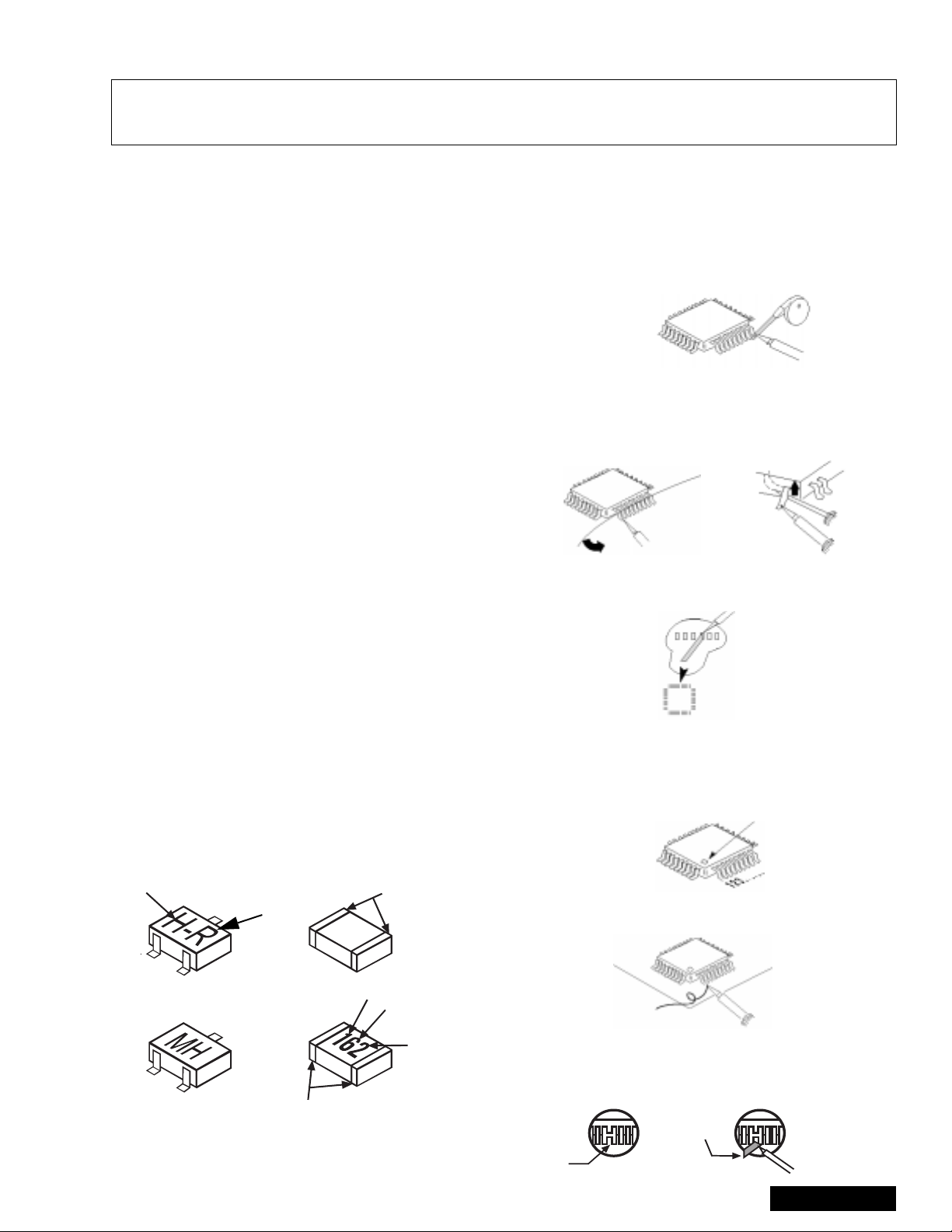
Service Notes
Note: These components are affixed with glue. Be careful not to break or damage any foil under the
component or at the pins of the ICs when removing. Usually applying heat to the component for
a short time while twisting with tweezers will break the component loose.
Leadless Chip Component
(surface mount)
Chip components must be replaced with identical chips
due to critical foil tr ack spacing. There are n o holes in
the board to mount standard transistors or diodes.
Some chip capacitor or resis tor board so lder pads may
have holes through the board, however the hole
diameter limits standard resistor replacement to 1/8
watt. Standard capacitor may also be limited for the
same reason. It is recommended that identical
components be used.
Chip resistor have a three digit numerical resistance
code - 1st and 2nd significant digits and a multiplier.
Example: 162 = 1 60 0 o r 1 .6 kΩ resistor, 0 = 0Ω (jumper).
Chip capacitors generally do not have the value
indicated on the capacitor. The color on the component
indicates the general range of the capaci tance.
Chip transistors are identified by a two let t er c ode . The
first letter indica ted the type an d the second letter, the
grade of transistor.
Chip diodes have a two lette r i den tif icati on c ode as per
the code chart an d are a dual diode pack with either
common anode or common cathode. Check the parts
list for correct diode number.
Component Removal
1. Use solder wick to remove s older from compo nent
end caps or terminal.
2. Without pulling up, carefully twist the component
with tweezers to break the adhesive.
3. Do not reuse removed leadless or chip
components since they are subject to stress
fracture during removal.
Chip Component Installation
1. Put a small amount of solder on the board
soldering pads.
2. Hold the chip component against the soldering
pads with tweezers or with a miniature alligator clip
and apply heat to th e pad area wi th a 30 watts iro n
until solder flows. Do not appl y heat for more than
3 seconds.
TYPE
Chip Components
GRADE
c
c
SOLDER
CAPS
How to Replace Flat-IC
- Required Tools -
• Soldering iron • De-solder braids
• Iron wire or small awl • M agn ifi er
1. Remove the solder from all of the pins of a Fla t-IC
by using a de-solder braid.
De-Solder
Flat-IC
2. Put the iron wire under the pins of the Flat-IC and
pull it in the direction indicated while heating the
pins using a soldering iron. a small awl can be
used instead of the iron wire.
Iron
Wire
Pull
Soldering
Iron
Soldering
Iron
3. Remove the solder from all the pads of the Fla t-IC
by using a de-solder braid.
Soldering
Iron
De-Solder
Braid
Flat IC
4. Position the new Flat-I C in place (app ly the pins of
the Flat-IC to the soldering pads where the pins
need to be soldered). Properly determine the
position of the sold ering pads and pins by correctly
aligning the polarity symbol.
Polarity Symbol
5. Solder all pins to the soldering pads using a fine
tipped soldering iron.
Braid
Awl
b
b
ANODES
MH DIODE
e
e
TRANSISTOR
COMMON
CATHODE
SOLDER
CAPS
CAPACITOR
1ST DIGIT
RESISTOR
2ND DIGIT
MULTIPLIER
=1600 = 1.6k
Solder
Soldering
Iron
6. Check with a magnifier for solder bridge between
the pins or for dry join t between pi ns and sold erin g
pads. To rem ove a solder bridge, use a de-solder
braid as shown in the figure below.
De-Solder
- 5 -
Solder
Braid
Braid
Soldering
Iron
Service Manual

Service Notes (Continued)
IMPORTANT: To protect against possible damage to
the solid state devices due to arcing or static discharge,
make certain that all ground wires and CRT DA G wire
are securely connected.
CAUTION: The power supply circuit is above earth
ground and the chassis cannot be polarized. Use an
isolation transformer when s ervicing the PTV to avoid
damage to the test equipment or to the chassis.
Connect the test equipment to the proper ground (( )
or ( )) when servicing, or incorrect voltages will
be measured.
WARNING: This PTV has been designed to meet or
exceed applicable safety and X-ray radiation protection
as specified by gove rnment a genci es and ind ependen t
testing laboratories.
To maintain original product safety design standards
relative to X-ray radiation and shock and fire hazard,
parts indicated with the s ymbol on the schematic
must be replaced with identi cal parts. Order parts from
the manufacturer’s parts center using the parts
numbers listed in this service manual, or provide the
chassis number and the part reference number.
For optimum performance and readability, all other
parts should be replaced with components of
identical specification.
Service Manual
- 6 -
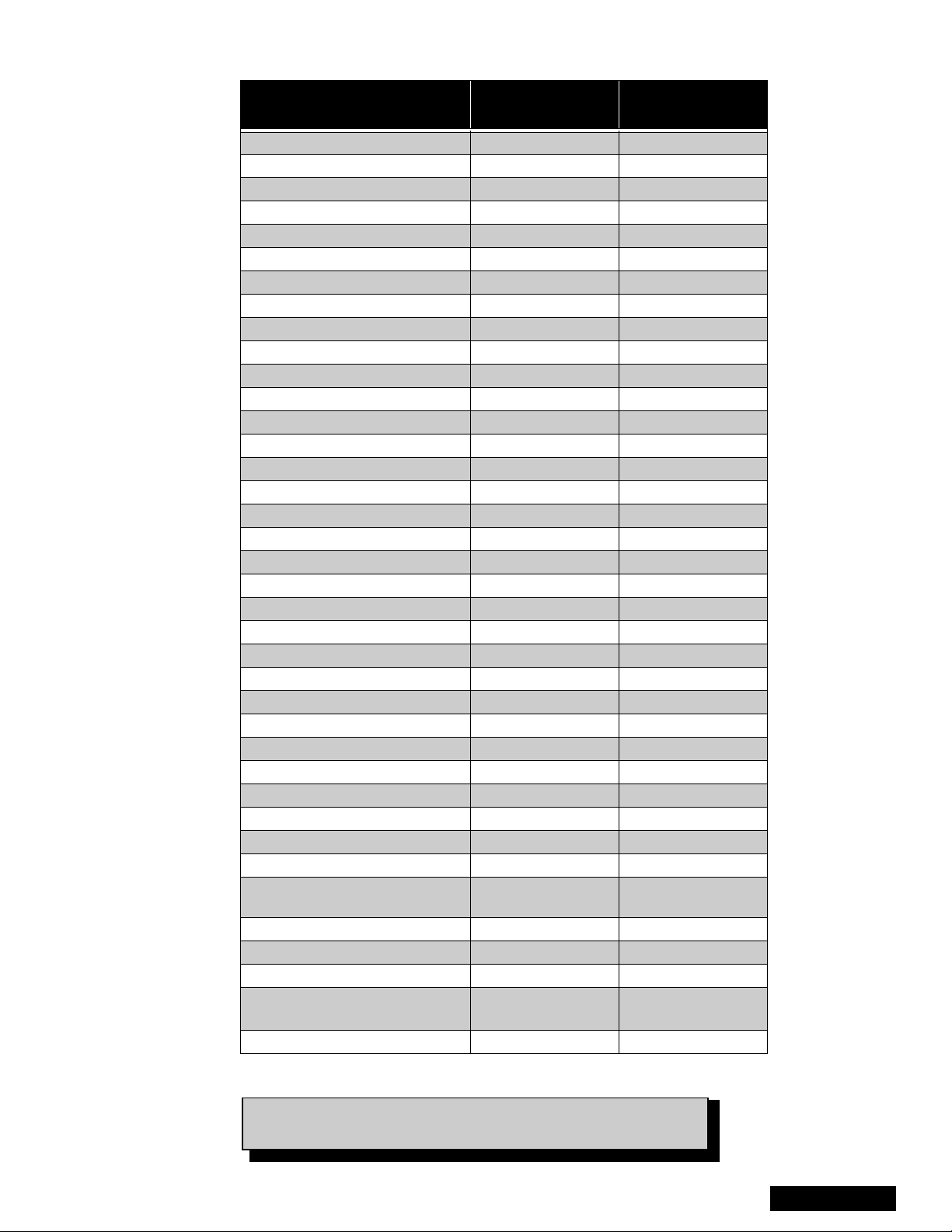
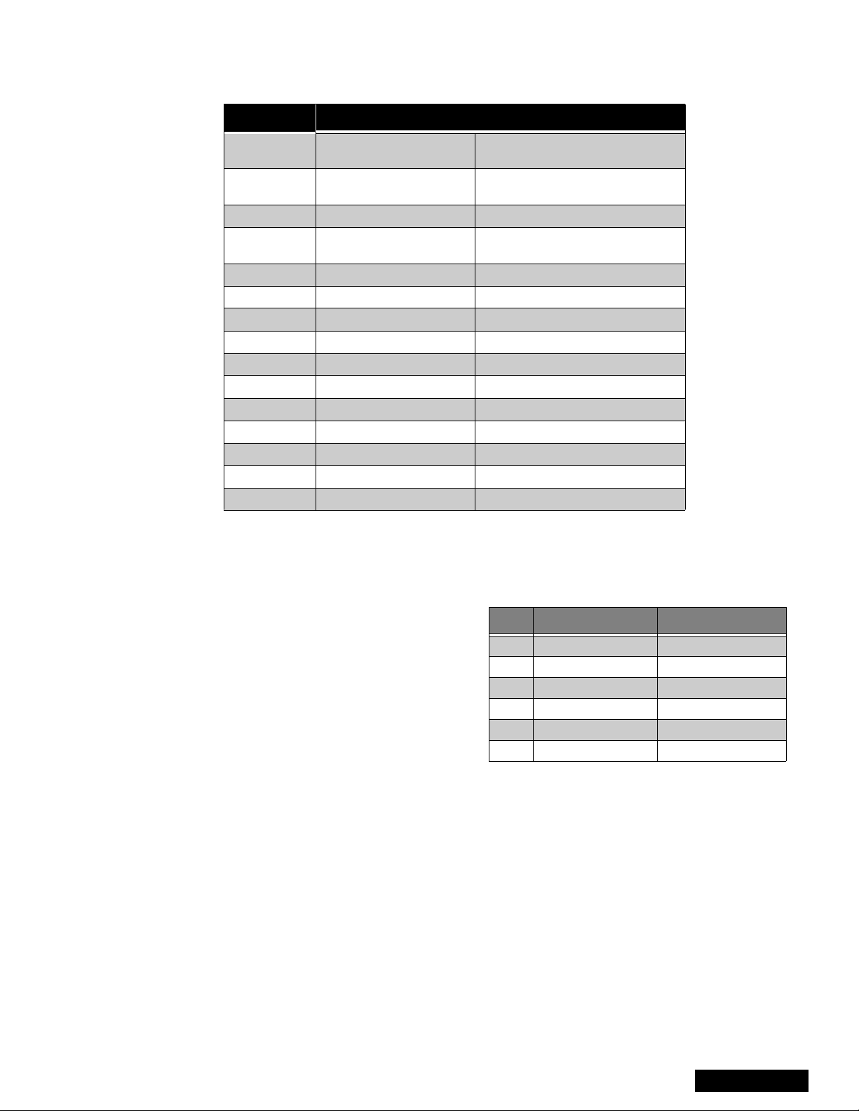
Feature Table
FEATURE
Chassis P4C P4C
Tunning system 144K 144K
# of channels 181 181
Menu language Eng/Span/Fr Eng/Span/Fr
Closed Caption (CC) X X
V-Chip (USA/Canada) X X
2RF X X
Antenna
Picture In Picture (PIP) 2T 2T
Remote control # EUR511151C EUR5111500
Screen protector X X
Comb filter 3DIG Y/C 3DIG
H. edge correction W/ VER W/ VER
Y NR X -VM X X
V/A norm Both Both
Color Temp X -Dyn color/Peak white X X
AIP X -Natural AI X -MTS/SAP/DBX X X
Bass/Bl/Treb control X X
AI sound Simple Simple
Spatializer X X
Built-in audio power 10W/CH (10%) 10W/CH (10%)
# of speakers 2 2
A/V in (rear/front) 4 (3/1) 3(2/1)
Component input 1 1
S-VHS in (rear/front) 2/1 1/0
Audio out Fixed & Variable Fixed & Variable
A/V Prog Out X -Dolby Center Ch In X -Dimensions mm
WxDxH in
Weight (kg/lbs) 116/255.7 116/255.7
Power source (V/Hz) 120V 60Hz 120V 60Hz
Anode voltage 31.5kV ± 1.0kV 31.5kV ± 1.0kV
Video input jack
Audio input jack 500mV RMS 47kΩ 500mV RMS 47kΩ
Input X X
PT-56SX30B
PT-56SX30CB
1196x683x1417
47x26.8x55.68
1V
75Ω, phono
p-p
jack
PT-56D30B
PT-56D30CB
1196x683x1417
47x26.8x55.68
1V
75Ω, phono
p-p
jack
Table 1: Feature Table
Specifications are subject to change without notice or obligation.
Dimensions and weights are approximate.
- 7 -
Service Manual
PCB Designation
BOARD
A-Board TNP2AH021 NIL AA Main chassis
B-Board TNPH0121 AG AG Power supply
C-Board TNPA1513 AB NIL Convergence
D-Board TNPA0609 AB AB Protection circuit
F-Board TNP2AA055 TNP2AA056AA Digital 3-line comb filter
G-Board TNP2AA049 AC NIL Front A/V connections
K-Board TNP2AA050 AC NIL Costumer controls
LB-Board TNPA0784 BA BA Blue CRT drive
LG-Board TNPA0783 BA BA Green CRT drive
LR-Board TNPA0782 BA BA Red CRT drive
N-Board TNP2AA027 AB AB 2nd tuner
R-Board TNPA0615 NIL NIL Remote sensor
PT-56SX30B
PT-56SX30CB
PT-56D30B
PT-56D30CB
BOARD DESCRIPTION
T-Board TNP2AA045 AD AD Line filter
X-Board TNP2AA063 NIL AA A/V inputs
Y-Board TNPA1059 AC AC PIP processing
Table 2: PCB Designation
Note: The C & F-Board (TNPA1513 &
TNP2AA055 & TNP2AA056AA) are
Non-Serviceable. If either board is
defective, replace the board with a
new one, and return the defective
board to the Service Center.
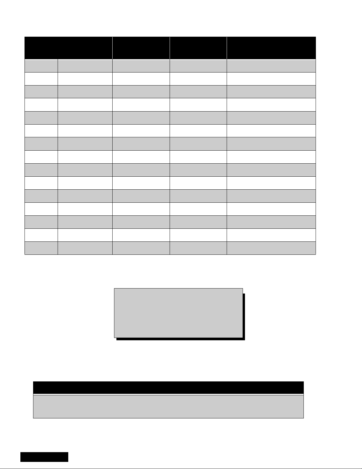
IMPORT ANT
This Simplified Service Manual includes only boards with particular application for the listed
models, for the rest of the schematics and PCBs, with gen eral use in this chassis, refer to
Main Service Manual MTNC000211C1 (PT-61D30B/CB)
Service Manual
- 8 -
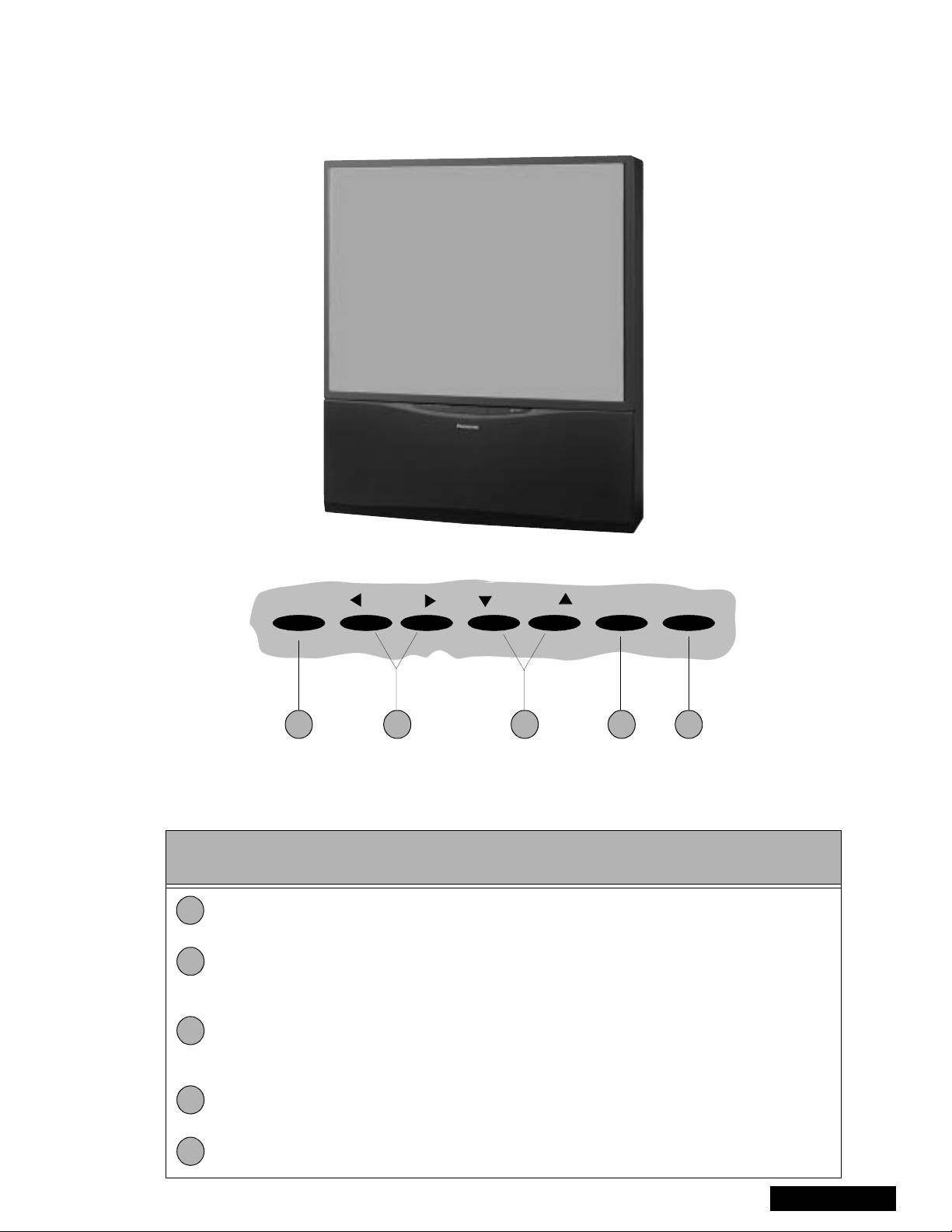
PTV - Location of Controls
Note: Appearance may vary
depending on models
characteristics.
POWER VOLUME CHANNEL ACTION TV/VIDEO
1 2 4 53
Figure 5. Location of Controls PTV
Quick Reference Control Operation
Quick Reference
Control Operation
1
2
3
Power - Press to turn ON or OFF.
Vo lu m e - Press to adjust Sound Le vel, or to adjus t Audio Menus, Video Me nus, and
select operating features when menus are displayed
Channel - Press to s elect programm ed channels. Pres s to highlight desired features
when menus are displayed. Also use to select Cable Converter box channels after
programming Remote Control Infra-red codes (the TV/AUX/CABLE switch must be set
in CABLE position).
4
Action - Press to displ ay Main Menu and access On Screen f eature and Ad justment
Menus.
5
TV/Video - Press to select TV or one of two Video Inputs, for the Main Picture or the
PIP frame (when PIP frame is displayed).
- 9 -
Service Manual
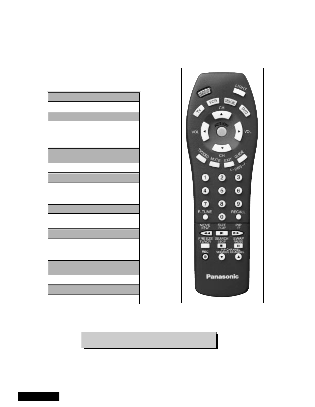
Remote - Location of Controls
POWER Button
Press to turn ON and OFF.
MUTE Button
Press to mute sound.
A second pres s resumes sound.
Press also to access and delete
Closed Caption display.
VCR, DVD, LD/CD, AUX, TV, CBL, DB S &
RCVR Buttons
Component function buttons
VOL (volume) Buttons
Press to adjust TV sound level.
Use with Channel buttons to
navigate in menus.
R-TUNE (Rapid Tune) Button.
Press to switch to the previous
channel.
ACTION Button
Press to display Main Menu and access or
exit On Screen features
and Adjustment Menus.
REW, PLAY, FF, TV/VCR, STOP, PAUSE,
REC & VCR CHANNEL Buttons
Component function buttons.
DBS EXIT& DBS GUIDE Buttons
DBS function buttons.
Figure 6. Location of Controls (Remote)
EUR511151C
Service Manual
For additional information for this rem ote please refer
to the Remote Guide, listed on the parts list.
- 10 -
BOARD DESCRIPTION
BOARD DESCRIPTION
A-Board Main chassis
B-Board Power supply
C-Board Convergence
D-Board Protection circuit
F-Board Comb filter
G-Board A/V connections
K-Board Costumer controls
LB-Board Blue CRT drive
LG-Board Green CRT drive
LR-Board Red CRT drive
N-Board 2nd tuner
R-Board Remote sensor
T-Board Line fil ter
X-Board A/V inputs
Y-Board PIP processing
MPU, Audio Amp, Convergence,
Amp and Volt Regulation
Horizontal Deflection and High
voltage protector
Digital Convergence
EHT protector, over deflection
blanking, Vertical stop blanking
Digital 3-line comb filter
Front A/V connections
Keyboard
2nd tuner processing
Remote control board
VAO,FAO
B+ Voltages Table
Preparation:
Set the following controls
Picture..........................Normal.
Bright ...........................Normal.
Volume.........................Min. (0).
Procedure:
1. Apply a monoscope pattern.
2. Connect the (-) Lead of the Digital Voltmeter to
TPBGND (Cold Ground) on B-Board.
3. Connect the (+) Lead of the Digital Voltmeter to
Test Point (On B-Board) and confirm the B+
Voltages (See Table 3).
No. Test Point Voltage
1 TPB140 138.5±1.0
2 TPB15 15.0
3 TPB7 7.0±0.5
4TP23 23.0
5 TPB23N -23.5±1.0
6 TPB32 16.5
±1.0
±1.0
±1.0
Table 3: B+ Voltages Table
- 11 -
Service Manual

REPLACEMENT PARTS LIST
Models: PT-56D30B, PT- 56D3 0CB, PT -5 6S X30 B & PT- 56 SX3 0CB
Important Safety Notice: Components printed in BOLD TYPE ha ve special characteristics important
for safety. When replacing any of these components use only manufacturer’s specified parts.
REF NO. PART NO. DESCRIPTION
CAPRISTORS
CR2801 EXNG131P365 RES-CAP 130PF/3.6 MEG
CR2802 EXNG131P365 RES-CAP 130PF/3.6 MEG
CAPACITORS
C001 ECA1CM101 CAP,E 100UF/16V
C004 TCUX1H103KBN CAP,C .01UF-K-50V
C005 ECA1CM101 CAP,E 100UF/16V
C006 ECA1HM4R7 CAP,E 4.7UF/50V
C010 ECA1CM101 CAP,E 100UF/16V
C011 ECJ2VC1H101J CAP,C 100PF-J-50V
C012 ECJ2VC1H101J CAP,C 100PF-J-50V
C013 ECA1HM220 CAP, E 22UF /50V
C014 ECA1HM220 CAP,E 22UF/50V
C015 ECJ2VC1H181J CAP,C 180PF-J-50V
C016 ECJ2VF1C105Z CAP,C 1.0UF-Z-16V
C017 ECJ2VF1C105Z CAP,C 1.0UF-Z-16V
C023 ECJ2VC1H181J CAP,C 180PF-J-50V
C024 ECA0JM102 CAP,E 1000UF/6.3V
C027 ECEA1HNR47U CAP,E .47UF-50V
C028 EEANA1E1R0B CAP,E 1.0UF-25V
C029 ECA1HM010 CAP,E 1.0UF/50V
C031 ECJ2VF1H103Z CAP,C .01UF-Z-50V
C034 ECJ2VB1H272K CAP ,C .0027UF-K-50V
C039 ECJ2VC1H220J CAP,C 22PF-J-50V
C040 ECJ2VC1H270J CAP,C 27PF-J-50V
C041 ECA0JM331 CAP,E 330UF/6.3V
C042 TCUX1H103KBN CAP,C .01UF-K-50V
C043 ECJ2VF1H103Z CAP,C .01UF-Z-50V
C045 ECA1CM101 CAP,E 100UF/16V
C046 ECJ2VF1H103Z CAP,C .01UF-Z-50V
PARTS LIST
C047 ECA0JM222 CAP,E 2200UF/6.3V
C048 ECJ2VF1H103Z CAP,C .01UF-Z-50V
C049 ECA1EM101 CAP,E 100UF/25V
C050 ECA1EM471 CAP,E 470UF/25V
C051 EEUFC1E470B CAP,E 47UF-25V
C052 TACCX103T50V CAP,C .01UF/50V
REF NO. PART NO. DESCRIPTION
C053 ECJ2VF1H103Z CAP,C .01UF-Z-50V
C054 TCUX1H103KBN CAP,C .01UF-K-50V
C055 ECJ2VF1H103Z CAP,C .01UF-Z-50V
C056 ECJ2VF1H103Z CAP,C .01UF-Z-50V
C081 ECA1HM010 CAP,E 1.0UF/50V
C101 ECJ2VF1H103Z CAP,C .01UF-Z-50V
C140 ECJ2VC1H270J CAP,C 27PF-J-50V
C301 ECEA1CN470U CA P,E 47UF-16V
C302 ECA1HM010 CAP,E 1.0UF/50V
C304 ECA1HM010 CAP,E 1.0UF/50V
C305 ECJ2VF1H103Z CAP,C .01UF-Z-50V
C306 ECA1HM220 CAP,E 22UF/50V
C307 ECJ2VF1H223Z CAP,C .022UF-Z050V
C308 ECA1HM3R3 CAP,E 3.3UF/50V
C309 ECEA1HN010U CA P,E 1UF/50V
C311 ECJ2VF1H103Z CAP,C .01UF-Z-50V
C312 ECA1HM100 CAP,E 10UF/50V
C313 ECA1VM470 CAP,E 47UF/35V
C314 ECA1CM101 CAP,E 100UF/16V
C315 ECA1EM220 CAP,E 22UF/25V
C316 ECA1HM4R7 CAP,E 4.7UF/50V
C317 ECA1HM4R7 CAP,E 4.7UF/50V
C318 ECJ2VF1H103Z CAP,C .01UF-Z-50V
C319 ECA1HM101 CAP,E 100UF/50V
C320 ECJ2VF1H103Z CAP,C .01UF-Z-50V
C321 ECA1CM101 CAP,E 100UF/16V
C330 ECJ2VC1H101J CAP,C 100PF-J-50V
C351 ECA2EM100 CAP,E 10UF/250V
C353 ECKD2H103PU CAP,C .01UF-P-500V
C354 ECA1CM101 CAP,E 100UF/16V
C356 ECKD3D332KB CAP,C .0033UF-K-2KV
C357 ECQB1H104JM CA P,P .1UF-J-50V
C359 ECKD3D102KB CAP,C .001UF-K-2KV
C360 ECA1CM470 CAP,E 47UF/16V
C361 TACCW1 01T50V CAP,C 100PF/50V
C363 ECKD3D102KB CAP,C .001UF-K-2KV
060-00
- 12 -
Parts List
 Loading...