

Panasonic PT-53TWD64 User Manual
High Definition Projection Television
Operating Instructions
Televisor de Proyección de Alta Definición
Instrucciones de Operación
™
PT-47XD64
PT-53XD64
PT-53TWD64
ATSC CERTIFIED
DIGITAL TELEVISION
*
*The presence of the DTV certification mark indicates that this
product will successfully receive digital television transmissions
that conform to any and all of the video formats described in the
ATSC Digital Television Standard.
TQB2AA0505 40527
PRINTED IN USA
IMPRESO EN EE.UU.
ENGLISH
IMPORTANT SAFETY INSTRUCTIONS
The lightning flash with arrow head
within a triangle is intended to tell the
WARNING
RISK OF ELECTRIC SHOCK
DO NOT OPEN
WARNING: TO REDUCE THE RISK OF ELECTRIC SHOCK DO NOT REMOVE
COVER OR BACK. NO USER-SERVICEABLE PARTS INSIDE. REFER SERVICING
TO QUALIFIED SERVICE PERSONNEL.
The Class II insulation symbol (square within a square) indicates that this product has been evaluated
and tested to comply with Class II insulation requirements.
WARNING: TO REDUCE THE RISK OF FIRE OR ELECTRIC SHOCK, DO NOT EXPOSE THIS
APPARATUS TO RAIN OR MOISTURE.
LIQUIDS, SUCH AS VASES, ON THIS APPARATUS.
DO NOT PLACE ANY OBJECTS FILLED WITH
user that parts inside the product are
a risk of electric shock to persons.
The exclamation point within a triangle
is intended to tell the user that
important operating and servicing
instructions are in the papers with the
appliance.
1. Read these instructions.
2. Keep these instructions.
3. Heed all warnings.
4. Follow all instructions.
5. Do not use this apparatus near water.
6. Clean only with dry cloth.
7. Do not block any ventilation openings. Install in accordance with the manufacturer’s instructions.
8. Do not install near any heat sources such as radiators, heat registers, stoves, or other apparatus (including
amplifiers) that produce heat.
9. Do not defeat the safety purpose of the polarized or grounding type plug. A polarized plug has two blades with
one wider than the other. A grounding type plug has two blades and a third grounding prong. The wide blade
or the third prong are provided for your safety. If the provided plug does not fit into your outlet, consult an electrician for replacement of the obsolete outlet.
10. Protect the power cord from being walked on or pinched particularly at plugs, convenience
receptacles, and the point where they exit from the apparatus.
11. Only use attachments/accessories specified by the manufacturer.
12. Use only with the cart, stand, tripod, bracket or table specified by the manufacturer, or sold
with the apparatus. When a cart is used, use caution when moving the cart/apparatus combination to avoid injury from tip-over.
13. Unplug this apparatus during lightning storms or when unused for long periods of time.
14. Refer all servicing to qualified service personnel. Servicing is required when the apparatus has been damaged in any way, such as power-supply cord or plug is damaged, liquid has been spilled or objects have fallen
into the apparatus, the apparatus has been exposed to rain or moisture, does not operate normally, or has
been dropped.
IMPORTANT INFORMATION
Important Information
FCC CAUTION: ANY CHANGES OR MODIFICATIONS TO THIS PTV RECEIVER NOT EXPRESSLY APPROVED BY
MATSUSHITA ELECTRIC CORPORATION OF AMERICA COULD CAUSE HARMFUL INTERFERENCE,
WHICH WOULD VOID THE USER’S AUTHORITY TO OPERATE THIS EQUIPMENT.
WARNING: AS WITH ANY SMALL OBJECT, SD CARDS CAN BE SWALLOWED BY YOUNG CHILDREN. DO NOT ALLOW
CHILDREN TO HANDLE THE SD CARD.
ENVIRONMENTAL NOTICE:
: SD Logo is a trademark.
Manufactured under license from BBE Sound, Inc.
Licensed by BBE Sound, Inc. under USP4638258, 5510752 and 5736897. BBE and
BBE symbol are registered trademarks of BBE Sound, Inc.
BBE ViVA HD3D (High Definition 3D) Sound provides musically accurate natural 3D
image with Hi-Fi sound. The clarity of the sound is improved by BBE while the width,
depth and height of sound image are expanded by BBE’S proprietary 3D sound process.
BBE ViVA HD3D Sound is compatible with all TV programs including news, music,
dramas, movies, sports and electronic games.
THIS PRODUCT UTILIZES CATHODE RAY TUBES (CRT) AND OTHER COMPONENTS
THAT CONTAIN LEAD. DISPOSAL OF THESE MATERIALS MAY BE REGULATED IN
YOUR COMMUNITY DUE TO ENVIRONMENTAL CONSIDERATIONS. FOR DISPOSAL OR
RECYCLING INFORMATION PLEASE CONTACT YOUR LOCAL AUTHORITIES, OR THE
ELECTRONICS INDUSTRIES ALLIANCE: <HTTP://WWW.EIAE.ORG.>
HDMI, the HDMI logo and High Definition Multimedia Interface are trademarks
or registered trademarks of HDMI Licensing LLC.
is a trademark of Cable Television Laboratories, Inc.
ENGLISH
BBE High Definition Sound restores clarity and presence for better speech intelligibility
High Definition Sound
This product incorporates copyright protection technology that is protected by U.S. patents and other intellectual property rights.
Use of this copyright protection technology must be authorized by Macrovision Corporation, and is intended for home and other
limited viewing uses only unless otherwise authorized by Macrovision. Reverse engineering or disassembly is prohibited.
U.S. Patents Nos. 4,631,603; 4,577,216; 4,819,098; 4,907,093; 6,381,747; and 6,516,132.
and music realism.
Important Information Regarding the use of Video Games, Computers, or Other Fixed Image displays
WARNING: The marking or retained image on the picture tube resulting from viewing fixed image is not an
operating defect and as such is not covered by Warranty.
The projection television is designed to display constantly moving images on the screen. Continuous viewing of stationary
images such as letterbox pictures on standard screen TVs (with top/bottom bars), non-expanded standard (4:3) pictures on wide
screen TVs (with side bars shown on each side of an image), stock market report bars (ticker running at the bottom of the
screen), video game patterns, fixed scoreboards, bright station logos, on-line (Internet) or repetitive computer style patterns
should be limited.
The extended use of fixed image program material can cause permanent picture tube damage, shown as a “shadow image”
viewable on normal programs. This type of irreversible picture tube deterioration can be limited by performing the following
steps:
• Limit the display of fixed image program material to no more than 15% of total viewing time per week.
• Turn the power off when not in use.
1 z
IMPORTANT INFORMATION
Important Information (contd.)
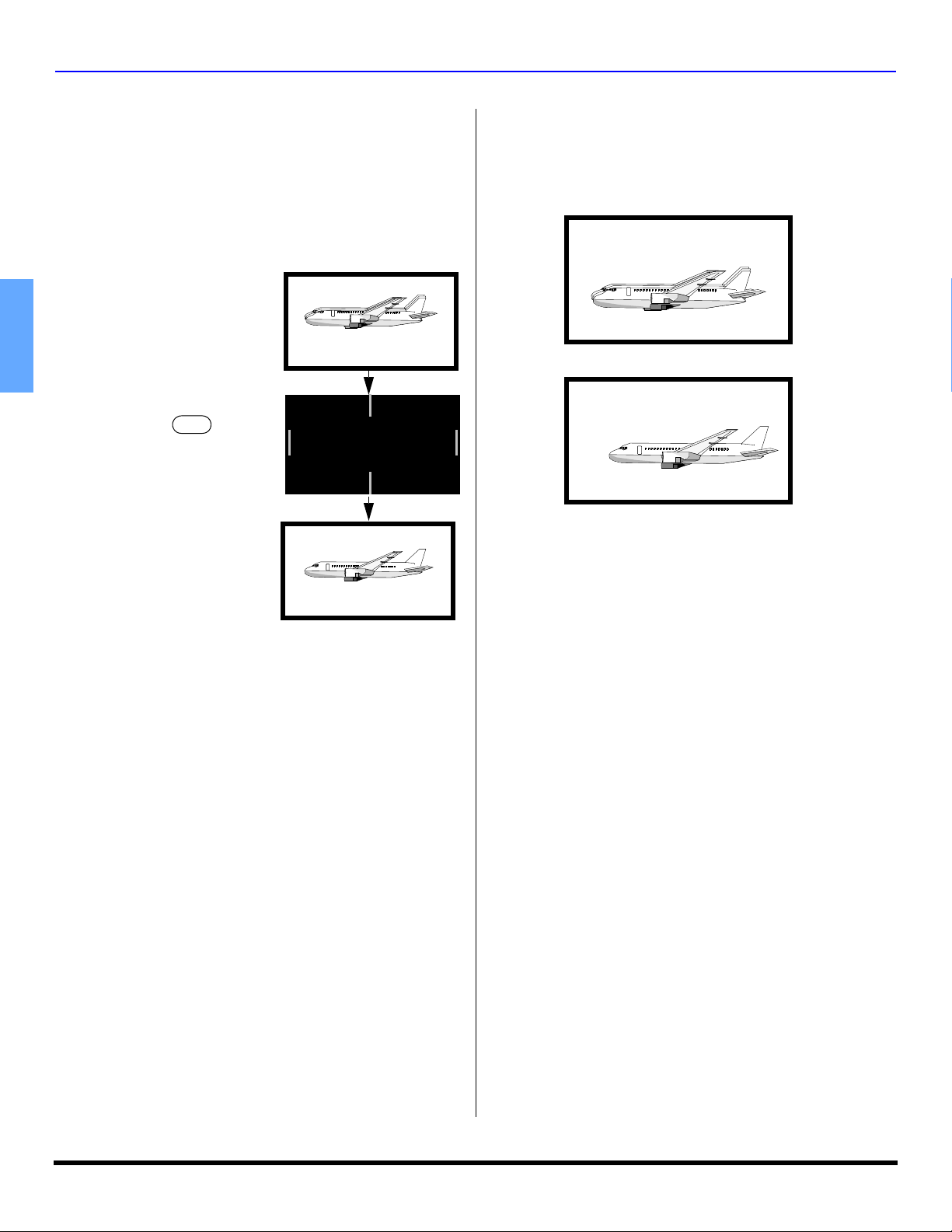
Information Regarding Auto Convergence
This feature is used to automatically adjust convergence. It is
recommended that this feature be used after moving the PTV or
any change of the magnetic field, such as changing PTV location
or adding additional speakers around the PTV.
Note: During auto convergence process the remote control has
no effect.
Normal picture with
convergence problem.
ENGLISH
AUTO CONV
Press the button
on the front control panel.
Note: Do not turn PTV off during
Auto Convergence process.
AUTO CONVERGENCE
IN PROCESS
The following diagram shows examples of a misaligned
image and a properly aligned image. Please refer to
pages 28 and 29 for detailed procedure on how to
adjust convergence manually.
Misconverged image
After auto convergence has
finished the normal picture
will be displayed, with
convergence problem
corrected.
Note: If convergence is not acceptable after auto convergence
is finished, refer to pages 28 and 29 to set convergence
manually.
Information Regarding Convergence
In the projection television, the image is formed by
projecting 3 different color images (red, green and blue)
onto the projection screen. Convergence refers to the
alignment of red, green and blue images on the
projection screen. When these images are properly
aligned (converged), you see a sharp and vibrant color
image. Sometimes, the three images may require
alignment. This is due to the effect of Earth’s magnetic field
on the projection tubes. Normally, adjustment is not
necessary after the initial alignment at the center of the
screen. It is possible to correct the color fringing on other
areas of the screen by using the buttons on the remote
control and by following the on-screen instructions in the
set-up menu. Please converge the images before using the
television for the first time.
Properly aligned image
Note:
• Make sure that the PTV is on for at least 20 minutes
before adjusting convergence, as described on pages 28
and 29.
FCC INFORMATION
This equipment has been tested and found to comply with
the limits for a Class B Digital Device in accordance with
the specifications in Part 15 of the FCC Rules. The limits
are designed to provide reasonable protection against
radio and television interference in a residential installation.
This equipment generates, uses and can radiate radio
frequency energy and, if not installed and used in
accordance with the instructions, may cause harmful
interference to radio communications. However, there is no
guarantee that interference will not occur in a particular
installation.
If this equipment does cause interference to radio or
television reception (which you can determine by turning
the equipment off and on), try to correct the interference by
one or more of the following measures.
• Reorient or relocate the receiving antenna.
• Increase the separation between the equipment and the
receiver.
• Connect the equipment into an outlet on a circuit
different from that to which the receiver is connected.
• Consult the dealer or an experienced radio/TV
technician for help.
2 z

Table of Contents
TABLE OF CONTENTS
Important Information ..................................... 1
Information Regarding The Use Of Video Games
Computers, Or Other Fixed Image Displays............. 1
Information Regarding Auto Convergence ................. 2
Information Regarding Convergence.......................... 2
Congratulations ............................................... 4
Customer Record........................................................ 4
Care and Cleaning...................................................... 4
Specifications.............................................................. 4
Feature Chart.............................................................. 4
Installation........................................................ 5
Television Location ..................................................... 5
Component Connection Cables.................................. 5
AC Power Supply Cord............................................... 5
Cable / Antenna Connection....................................... 5
Remote Control Battery Installation ............................ 5
First Time Setup............................................... 6
Front and Rear View of the High Definition
Projection Television.................................... 7
Optional Equipment Connections.................. 8
VCR Connection ......................................................... 8
CableCARD Connection ............................................. 8
Digital TV - Set-Top Box (DTV-STB) or DVD Player
Connection................................................................ 8
Front Control Panel...................................................... 8
HDMI Input Connection .............................................. 9
Digital Audio Out connection ...................................... 10
Program Out Connection ............................................ 10
Amplifier Connection (Analog) .................................... 10
PIP and SPLIT Operation ............................. 11
PIP Operation ............................................................ 11
SPLIT Operation ........................................................ 11
PIP And Split Operational Buttons ............. 11
TV/Video Button ......................................................... 11
Search Button............................................................. 11
Move Button ............................................................... 12
PIP MIN and PIP MAX Buttons .................................. 12
Freeze Button............................................................. 12
Main Picture Freeze Feature...................................... 12
PIP, Split and Freeze Mode Buttons
Operational Chart .................................................... 12
Special Features of the High Definition
Projection Television ................................ 13
Special Remote Buttons .............................. 14
Remote Control Operation .......................... 15
Programming the Remote Control.............................. 16
Programming Without a Code .................................... 16
Component Codes ..................................................... 16
Operating Components with Remote Control............. 19
Basic Menu Navigation................................. 21
Menu Operations........................................... 22
Picture ........................................................................ 22
Audio .......................................................................... 22
Channel ...................................................................... 23
Photo Viewer™ Operation.......................................... 24
Timer .......................................................................... 26
Set Up ........................................................................ 27
Lock............................................................................ 30
Glossary and Acronyms............................... 33
Troubleshooting Chart ................................. 34
Index............................................................... 36
ENGLISH
Note: The warranty and service center information is located in the back of this manual.
Read these instructions completely before operating television.
Contents are subject to change without notice or obligation.
Copyright 2004 by Matsushita Electric Corporation of America. All rights reserved.
Unauthorized copying and distribution is a violation of law.
3 z
CONGRATULATIONS
Congratulations
Your new High Definition Projection Television (PTV)
features state-of-the-art technology for high quality picture
and sound with complete audio/video connections for your
home theater system. Your PTV is designed to give you
many years of enjoyment. It was thoroughly tested and
tuned at the factory for best performance.
Customer Record
The model and serial number of this product are located on
the back of the TV. You should note the model and serial
number in the space provided and retain as a permanent
record of your purchase. This will aid in identification in the
event of theft or loss. Product registration for U.S. customers
is available at: www.prodreg.com/panasonic.
ENGLISH
Model
Number
Serial
Number
Care and Cleaning
Projection Screen (Turn PTV Off)
The projection screen is a high precision lens system which
has a protective screen. The protective screen is fully
washable with the following precautions:
• Use a mild soap solution or window cleaner and a clean
cloth.
• DO NOT USE ABRASIVE CLEANERS.
• Do not use laundry detergent or automatic dishwasher
soap.
• Do not use alcohol, ammonia, or petroleum based
products.
• Avoid excessive moisture and wipe dry.
• Prevent solution from running into the receiver below.
• Avoid bumping or scraping the screen.
Warning: Do not spray any type of cleaning fluid directly on the
screen.
Cabinet and Remote Control
• For cabinets and remote control, use a soft cloth
dampened with water or a mild detergent solution. Avoid
excessive moisture and wipe dry.
• Do not use benzene, thinner or other petroleum based
products.
Specifications
Specifications are subject to change without notice or
obligation.
Power Source
PT-47XD64 (4.1A)
PT-53XD64 (4.1A)
PT-53TWD64 (4.1A)
Channel Capability ATSC/NTSC
HDMI Input jack Type A
Digital Audio Out jack PCM / Dolby* Digital Fiber Optic
Component Video Inputs
(Y / P
/ PR)
B
Video Input Jacks 1Vp-p, 75 Ohm, Phono Jack Type
Audio Input Jacks 500mV RMS 47K Ohm
Video out jack 1Vp-p, 75 Ohm, Phono Jack Type
Audio Output Jacks 500mV RMS 4.7K Ohm
S-Video Input Jacks S-Video (Y-C) Connector
120V AC, 60Hz
VHF/UHF- 2-69
CATV - 1-135
75 Ohm, Phono Jack Type
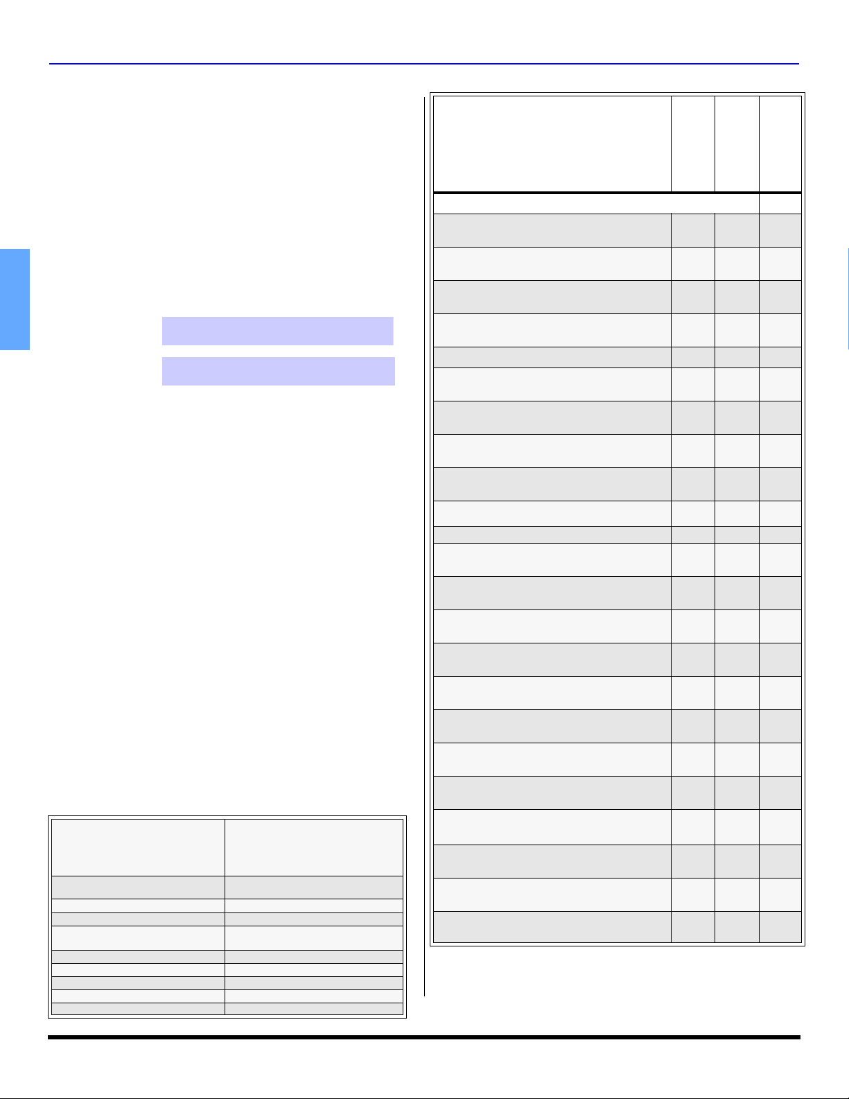
Feature Chart
MODELS
PT-47XD64
FEATURES
ATSC DIGITAL TUNER
PHOTO VIEWER™
CableCARD™ INTERFACE
2 TUNER PIP/SPLIT SCREEN DISPLAY
75 OHM UHF/VHF INPUT
ZOOM ADJUST (SIZE AND POSITION)
PROTECTIVE SCREEN
CLOSED CAPTIONING
V-CHIP CAPABILITY
DIGITAL SCAN RATE
NTSC LINE-DOUBLER
VIDEO NORM
AUDIO NORM
STEREO AND SAP
AI SOUND
BASS/BALANCE/TREBLE
SURROUND
BBE
HDMI/HDCP INPUT
A/V IN (REAR/FRONT)
DIGITAL AUDIO OUT
S-VIDEO INPUTS
COMPONENT VIDEO INPUTS
*Manufactured under license from Dolby Laboratories.
“Dolby” and the double-D symbols are trademarks of Dolby Laboratories.
• • •
• • •
• • •
• • •
2 2 2
• • •
• • •
• • •
• • •
1080i,
540p
540p 540p 540p
• • •
• • •
• • •
• • •
• • •
• • •
• • •
• • •
4
(3/1)4 (3/1)4 (3/1)
• • •
• • •
• • •
PT-53XD64
1080i,
540p
1080i,
540p
PT-53TWD64
4 z

Installation
INSTALLATION
Television Location
This unit can be used as part of an entertainment center.
Consult your dealer for available options.
• Avoid excessive sunlight or bright lights, including
reflections.
• Keep away from excessive heat or moisture. Inadequate
ventilation may cause internal component failure.
• Fluorescent lighting may reduce remote control
transmitting range.
• Keep away from magnetic equipment, including motors,
fans and external speakers.
Component Connection Cables
Shielded audio and video cables should be used between
components. For best results:
• Use 75-ohm coaxial shielded cables.
• Use appropriate input and output connectors, that match
your component connectors.
• Avoid long cables to minimize interference.
AC Power Supply Cord
CAUTION: TO PREVENT ELECTRIC SHOCK,
MATCH WIDE BLADE OF PLUG TO WIDE SLOT
OF AC OUTLET AND FULLY INSERT. DO NOT
USE A PLUG WITH A RECEPTACLE OR OTHER
OUTLET UNLESS THE BLADE CAN BE FULLY INSERTED TO
PREVENT BLADE EXPOSURE.
PROTECT POWER CORDS FROM BEING WALKED ON, ROLLED
OVER, CRIMPED, BENT, OR PINCHED, PARTICULARLY AT PLUGS,
CONVENIENCE RECEPTACLES, AND THE POINT WHERE THEY EXIT
FROM THE APPARATUS.
Polarized plug
Cable / Antenna Connection
For proper reception of analog or digital cable channels, a
cable service connection is required.
Cable Connection
Connect the cable supplied by your local
cable company to ANTENNA (A)
connection on back of television. Select
Cable mode and ANTENNA (A) in SET UP
menu under Program CH (Program
Channels).
Antenna Connection
• For proper reception of digital and analog VHF/
UHF channels, an external antenna is required. For
best reception an outdoor antenna is
recommended.
• Connect home antenna to
either ANT (A) or ANT (B)
connection on back of the
television. Select Antenna
mode for ANTENNA (A) or
(B) in Input Setup under
Program CH in Setup menu.
Note: Cable Mode is preset at the factory. Antenna users must
change to ANTENNA Mode for ANTENNA (A) in the Set
Up menu. If you have both Cable and Antenna, the
Cable must be connected to ANT (A).
Incoming Cable from
Cable Company
75 Ohm ANT A
Incoming Cable from
Home Antenna
External Shelf (mounted on top)
(models PT-47XD64 and PT-53XD64 only)
For your convenience, optional devices such as a Satellite
Receiver, a Cable Box, a DVD player, a VCR or a center channel
speaker can be placed on this shelf.
CAUTION: The weight limit of this shelf must not
exceed 25 lbs.
Remote Control Battery Installation
Use two AA batteries (supplied):
1
1. Remove battery cover by pushing in on the catch while
lifting the cover up.
2. Install batteries by matching (+) and (-) polarity signs in
the compartment.
3. Re-insert the cover and press down the cover until it
snaps shut.
Note: Incorrect installation can cause battery leakage and
corrosion that will damage the Remote Control.
Precautions
• Replace batteries in pairs.
• Do not mix battery types (example: zinc carbon with
alkaline).
• Do not recharge, heat, short circuit, disassemble, or burn
batteries.
• Battery replacement is necessary when the remote
control acts sporadically or stops operating the selected
device.
2 3
+
-
+
-
+
-
+
+
ENGLISH
5 z

FIRST TIME SETUP
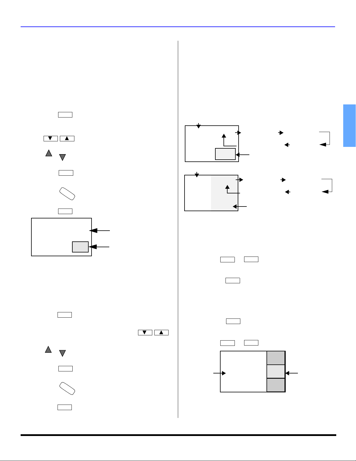
First Time Setup
For your convenience, First Time Set up menu will be
displayed on screen when the set is turned on for the first
time. If needed, follow the menus and procedures
displayed on-screen for setting up the features.
Input Setup
To select the configuration of RF input depending on the
signal source.
Note: No video will be displayed in this setup mode.
Procedure
• Press VOL to select Cable only, Cable/Antenna or
Antenna only.
• Press the OK button to underline your selection.
ENGLISH
First time setup
Input Setup
Auto Scan
Convergence
Setting
Connect Cable to Antenna (A)
Cable only
Change your Input Setup
and press OK
• When the next screen is displayed, press OK button to
start the Auto Scan. All available channels with a signal
will be programmed into memory.
Auto Scan
This feature allows you to selectively auto scan channels.
You can Scan All, Analog only channels or Analog & Digital
channels.
Procedure
• Press OK button to start Auto Scan.
First time setup
Input Setup
Auto Scan
Convergence
Scan All
Antenna (A) Analog
Antenna (A) Analog & Digital
Antenna (B) Analog
Antenna (B) Analog & Digital
SELECT
MENU
to return
OK
EXIT
Convergence
This menu lets you set the green CRT alignment and the center
convergence. Follow the instructions on-screen to perform
convergence. After convergence is performed, press EXIT to
return to normal viewing.
First time setup
Input Setup
Auto Scan
Convergence
Press OK to go to
Convergence setup
AUTO CONVERGENCE
IN PROCESS
SELECT
MENU
to return
OK
EXIT
• After Auto Scan is completed the PTV tunes to the first
channel found during auto scan.
Notes:
• If the EXIT button is pressed at anytime during auto
scan, the First Time Setup menu will be cancelled and
the PTV will tune to analog channel 2 on ANTENNA (A).
• If a CableCARD is present during the First Time Setup
and Antenna (A) is set to cable, Antenna (A) will not be
scanned due to the CableCARD providing the channel
map.
• Auto Scan must be done when you select the input
signal for the first time or whenever you change the
antenna configuration.
6 z
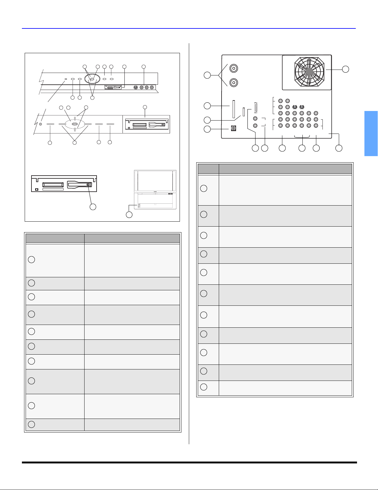
FRONT AND REAR VIEW OF THE HIGH DEFINITION PROJECTION TELEVISION
Front and Rear View of the High Definition Projection Television
Front Panel Rear Panel Jacks
Front Panel for PT-47XD64 and PT-53XD64
5 6
ON/OFF
INDICATOR
POWER
1
3 7
POWER TV/VIDEO MENU AUTO CONV.
VOL
2
1
5&7
VOL
3
CH
O
T
C
U
O
A
/
N
V
K
.
O
CH
5
CH
K
O
VOL
CH
4
TV / VIDEOVOL
2
MENU
SD CARD
6
8 9
S-VIDEO VIDEO 4 L- AUDIO -R
8
Front Panel for PT-53TWD64
Note: The ON/OFF indicator LED (red) will be lit when the
set is on.
SD CARD
SD slot
PC slot
Photo Viewer™
10
9
CH
POWER
VOL
MENU
TV / VIDEOVOL
K
O
CH
PT-53TWD64
1
2
3
4
Item # Description
1
2
ANT A
Cable In
ANT B
CableCARD
INTERFACE
DIGITAL AUDIO OUT
TM
SERVICE
ONLY
HDMI
A/V IN
L
AUDIO IN
R
AUDIO
VIDEO
Y
P
B
P
R
COMPONENT
VIDEO INPUT
5 6 7 8 9
Antenna Inputs
ANT A - Connect Cable Antenna or Terrestrial Antenna to
this input to receive Digital channels.
ANT B - If you have both Cable antenna and Terrestrial
antenna, connect the Terrestrial antenna to ANT B.
CableCARD™ INTERFACE
Insert the CableCARD module from the Cable company to
receive premium digital service.
2
1
S-VIDEO
INPUT1INPUT2INPUT3PROG
OUT
VIDEO
L
R
TO
AUDIO
AMP
10
11
ENGLISH
Feature Description
Toggles power OFF/ON
1
POWER
Note: In case of front panel lock-up or
remote control hang-up, press and hold
POWER button for more than 5 seconds
until the unit resets itself.
2
TV/VIDEO
3
CH and CH
Changes Input source
Tunes to lower or higher channels,
navigate up/down in menus.
Decrease or increase volume, navigate
4
VOL and VOL
5
OK
6
MENU
7
Auto Convergence
8
Photo Viewer™
9
Video 4
left/right in menu, adjust selected feature
Completes channel specification, press to
accepts menu and sub-menu selection.
Display or remove menu or return one
Press this button to start auto
Lets you display JPEG images recorded
on memory cards by a digital camera.
The Photo Viewer™ is located behind the
Analog inputs for external devices
Note: For model PT-53TWD64, Video 4
input is located on the bottom left pillar of
in menu.
step backward in menus.
convergence process.
door marked SD.
the cabinet.
10
11
SERVICE ONLY
3
4
5
Card slot used by a certified service technician only. Do not
insert any memory card into this slot.
DIGITAL AUDIO OUT
5.1 Dolby Digital surround sound optical output.
HDMI (High Definition Multimedia Interface)
Input that accepts uncompressed digital signal and multi
channel digital audio signal.
AUDIO IN
6
Use these audio inputs when DVI devices are connected to
HDMI input using the DVI to HDMI adaptor.
COMPONENT VIDEO (Y-PB-PR) INPUTS
7
8
Use these jacks for connecting devices such as a DVD
player or Set Top Box.
INPUTS 1, 2 and 3
Composite inputs for connecting VCR and other devices.
PROG OUT
9
Terminals that output fixed audio and NTSC composite
video.
TO AUDIO AMP
Analog Audio Output to connect to an analog amplifier
Cooling fan
10
Eject button
Push this button to eject PC card.
7 z
OPTIONAL EQUIPMENT CONNECTIONS
Optional Equipment Connections
Note: The remote control must be programmed with supplied
codes to operate the optional equipment.
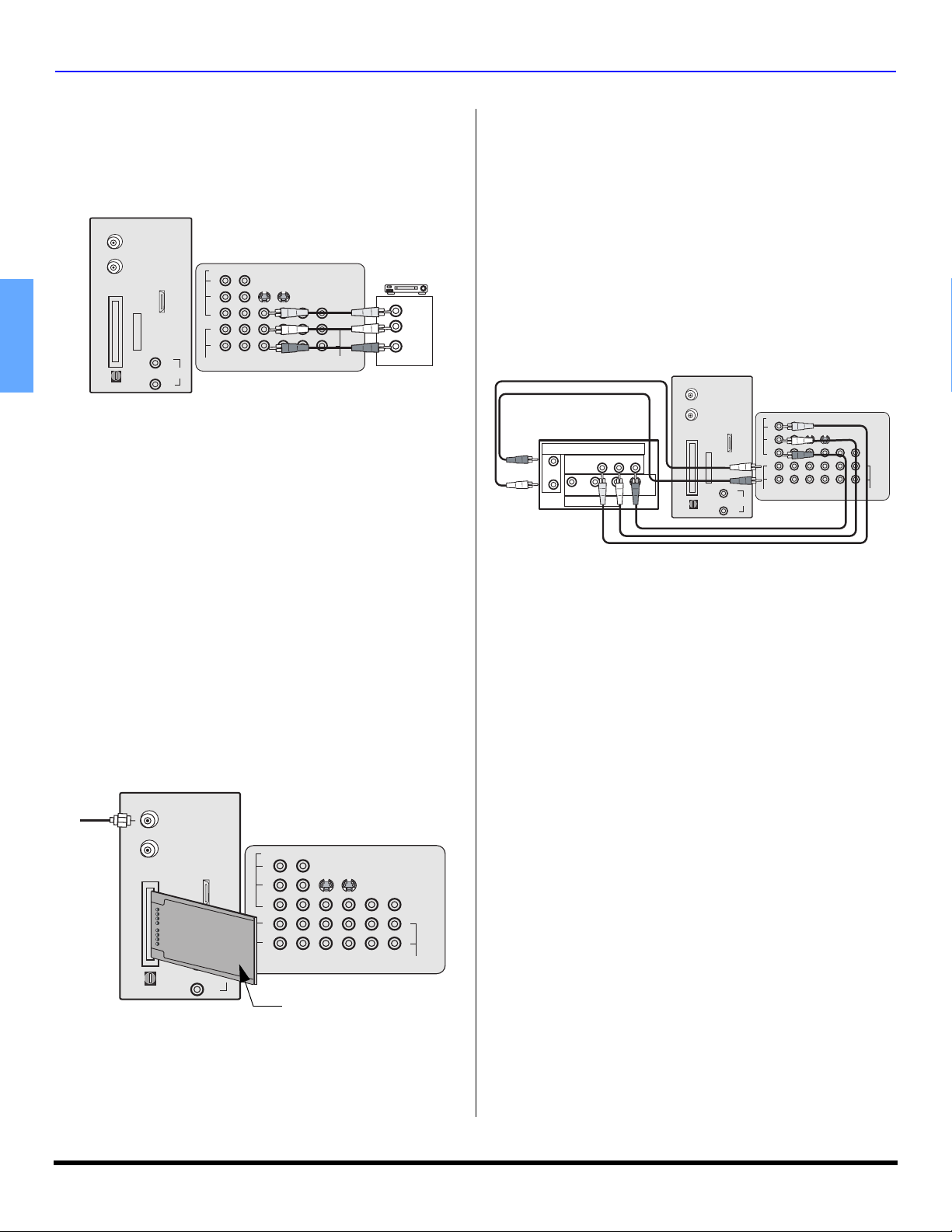
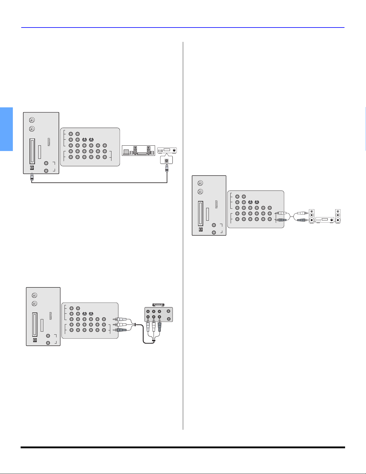
VCR Connection
Follow this diagram when connecting your television to a
VCR only.
ANT A
Cable In
ANT B
TM
CableCARD
INTERFACE
SERVICE
ONLY
ENGLISH
DIGITAL AUDIO OUT
Procedure
• Press the TV/VIDEO button on the remote control to
select the video input (VIDEO 1, VIDEO 2, etc.)
connected to your VCR.
• Begin the video.
CableCARD™ Connection
This module allows you to tune digital and high definition
cable channels through the cable antenna. Consult your
Cable company on the availability of this module.
Note: A Digital Cable Subscription is required. (refer to pg. 29)
Procedure
• Connect the Cable antenna to ANT A/Cable In input on
the back of the PTV.
• Insert the CableCARD module (upper side facing left)
into the CableCARD slot on the back of the PTV.
Notes:
• Left side is the upper side of the DCM cards.
• Do not insert a PCMCIA card into the CableCARD slot.
• Choose Cable mode for Antenna (A) in Input Setup.
• Follow the instructions on screen.
ANT A
Cable In
Incoming
cable
signal
ANT B
CableCARD
INTERFACE
DIGITAL AUDIO OUT
TERMINALS ON BACK OF PROJECTION TELEVISION
VIDEO
AV IN
L
R
TM
I
NSER
CableCARD
Y
P
B
P
R
L
R
AUDIO
HDMI
A/V IN
TT
H
IS END
TM
L
AUDIO IN
2
1
COMPONENT
INPUT1INPUT2INPUT3PROG
VIDEO INPUT
CABLES NOT SUPPLIED
TERMINALS ON BACK OF PROJECTION TELEVISION
VIDEO
Y
P
B
PR
L
R
AUDIO
COMPONENT
VIDEO INPUT
HDMI
AUDIO IN
SERVICE
ONLY
R
S-VIDEO
VIDEO
L
R
TO AUDIO
OUT
AMP
S-VIDEO
2
1
INPUT1INPUT2INPUT3PROG
Left side (upper side)
of card
VIDEO OUT
AUDIO OUT
OUT
VCR
L
R
VIDEO
L
R
PLAY
R
FF
E
W
STOP
TO AUDIO
AMP
Digital TV-Set-Top-Box (DTV-STB) or DVD Player Connection
The television is capable of displaying 1080i, 480p and 480i
signals when connected to a DTV tuner set-top-box (STB) or a
DVD player. In order to view DTV programming, the STB must
be connected to the component video inputs (Y,P
B,PR
) of the
PTV. Select the output of the STB to either 1080i or 480p.
This television also utilizes a progressive scan doubler, which
de-interlaces the NTSC signal and progressively scans the
image. This allows you to sit close to the TV and not see the
thin black horizontal lines (venetian blind effect) associated
with interlaced TV pictures.
Use this diagram to connect a DVD player to the back of your
projection television.
TERMINALS ON BACK OF PROJECTION TELEVISION
ANT A
Cable In
TERMINALS ON BACK OF DTV-STB OR
DVD PLAYER
DIGITAL TV OUTPUT
Y
P
R
B
P
MAIN
VIDEO
L-AUDIO-R
R-AUDIO-L - VIDEO S-VIDEO
NTSC OUTPUT
ANT B
TM
CableCARD
INTERFACE
SERVICE
ONLY
DIGITAL AUDIO OUT
HDMI
AV IN
L
AUDIO IN
R
VIDEO
Y
B
P
P
R
L
R
2
1
AUDIO
COMPONENT
VIDEO INPUT
CABLES NOT SUPPLIED
S-VIDEO
INPUT1INPUT2INPUT3PROG
VIDEO
L
R
TO AUDIO
OUT
AMP
Note: There are two set of three video jacks, Y, PB, and PR.
Separate component color inputs provide luminance and
color separation. Use the L (left) and R (right) audio
inputs.
Front Control Panel
The front control panel can be used to access menus and
switch video mode when the remote control is not available.
second VCR, Camcorder, a video disc player, video game
equipment or DSS equipment can also be connected to the
video inputs. See the optional equipment manual for details
Procedure
• Connect equipment to front Audio/Video input jacks.
• Press TV/VIDEO button to select VIDEO 4 input mode.
Note: For model PT-53TWD64, VIDEO 4 input is
located on the bottom left pillar of the cabinet.
• Operate optional equipment as instructed in the optional
equipment manual.
A
.
Note: If you experience keyboard or remote control function
hang-up when using CableCARD module, unplug the
PTV and plug it back on and try the controls again. If this
condition still exists, please call Panasonic Customer
Call Center for further instructions.
8 z
HDMI (High Definition Multimedia Interface)
input connection
About HDMI
HDMI is the first all digital consumer electronics A/V
interface that supports several uncompressed standard,
enhanced and high definition video format as well as
existing multi-channel audio format. One jack supports both
video and audio information. The HDMI/HDCP
be connected to an EIA/CEA 861
2
compliant consumer
electronic device, such as a set top box or DVD player
equipped with a HDMI or DVI output connection. By
inputting a High-bandwidth Digital Content Protection
(HDCP) high definition picture source to the HDMI terminal
of this PTV, high definition pictures can be displayed on the
screen in their digital form. The HDMI input terminal is not
intended to be used with personal computers. This PTV is
compatible with 1080i, 480p and 480i formats. Select the
output of the connecting to device to match that of the PTV.
Notes:
1. HDMI/HDCP = High Definition Multimedia Interface /
High-Bandwidth Digital Copy Protection.
2. EIA/CEA-861 Profiles compliance covers profiles for
transmission of uncompressed digital video including
high bandwidth digital content protection.
Compatible formats
This PTV is compatible with following formats. Please set
the connecting device to following format.
Video signal
Format No of dots
1080i 1920 x 1080i 59.94 / 60
540p (480p)
720 x 480p
640 x 480p
540p (480i) 720 x 480i 59.94 / 60
Audio signal
When digital audio is included in the HDMI connection,
the compatible sampling frequencies are 48 KHz /
44.1Khz / 32 Khz.
Vertical scanning
frequency (Hz)
59.94 / 60
59.94 / 60
1
input can
OPTIONAL EQUIPMENT CONNECTIONS
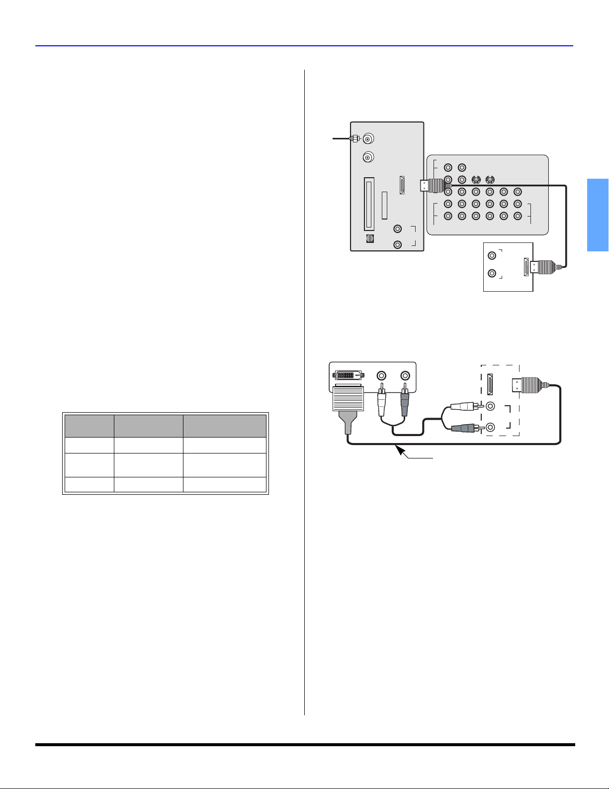
Connection diagram
Follow the diagram below to connect the PTV to a set top box or a
DVD player.
ANT A
Incoming
Cable
Connecting devices with DVI out
EXTERNAL DIGITAL COMPONENT
Procedure
Notes:
Cable In
ANT B
TM
CableCARD
INTERFACE
SERVICE
ONLY
DIGITAL AUDIO OUT
HDMI
TERMINALS ON BACK OF PROJECTION TELEVISION
VIDEO
AV IN
L
AUDIO IN
R
Y
P
B
P
R
L
R
AUDIO
COMPONENT
VIDEO INPUT
CABLES NOT INCLUDED
2
1
INPUT1INPUT2INPUT3PROG
EXTERNAL DIGITAL
COMPONENT
S-VIDEO
VIDEO
L
R
TO AUDIO
OUT
AMP
LR
HDMI
AUDIO OUT
OUT
* The connector on the PTV is HDMI Type A connector.
DVI OUT L- AUDIO OUT - R
HDMI
AV IN
L
AUDIO IN
R
DVI to HDMI adaptor cable
• Connect the HDMI output from the set top box or a DVD
player to the HDMI input on the back of the PTV.
• Press TV/VIDEO button on the remote control to select
HDMI input. The connector on the PTV is HDMI Type A
connector.
• If the external device has DVI output only, use a DVI to
3
HDMI adaptor cable*
to connect to the HDMI jack on
the PTV. Also, connect the Audio Out signal from the
external device (set top box or DVD player) to the Audio
4
jacks below the HDMI input.
In*
• If you cannot display the picture because of your Digital
Set Top Box does not have a Digital Out terminal setting,
use the Component Video Input (or the S-Video Input or
Video Input). In this case, the picture will be displayed as
an analog signal.
*3. HDMI-DVI conversion cable (TY-SCH03DH) available
on Panasonic Website: www.panasonic.com.
*4. Please refer to page 23 for Audio setting detail.
ENGLISH
9 z
OPTIONAL EQUIPMENT CONNECTIONS
Digital Audio Out Connection
Use the diagram below to connect the Digital Audio Output of your
HDTV Projection Television to a Dolby Digital decoder.
Digital Audio Out
Dolby Digital 5.1 channel surround sound delivers digital-quality
sound. Dolby Digital provides five discrete full-bandwidth
channels for front left, front right, center, surround left and
surround right, plus a LFE (Low Frequency Effect) subwoofer
channel. For a full Home Theater sound experience, an external
Dolby Digital decoder and a multichannel amplifier must be
connected to the Digital Audio Out jack on the PTV.
ANT A
Cable In
ANT B
TM
CableCARD
INTERFACE
SERVICE
ENGLISH
ONLY
DIGITAL AUDIO OUT
Procedure
• Connect the Digital Audio cable from the Digital Audio
Note: When ATSC channel is selected, the output from the
TERMINALS ON BACK OF PROJECTION TELEVISION
VIDEO
A/V IN
L
AUDIO IN
R
Y
P
B
P
R
L
R
2
1
AUDIO
COMPONENT
VIDEO INPUT
CABLES NOT SUPPLIED
S-VIDEO
INPUT1INPUT2INPUT3PROG
OUT
VIDEO
L
R
TO AUDIO
AMP
Six channel Speaker system
HDMI
Out jack on the PTV to the Digital Audio In connection on
the Dolby Digital decoder.
Digital Audio Out jack will be Dolby Digital. But, if NTSC
channel is selected, the output will be PCM.
Amplifier
90.7 MHZ
OPTICAL IN
• Program Out signal may not be available when
component input is selected for main picture.
• Program Out signal is available when receiving digital
channel. However, all digital formats are down converted
to composite NTSC video.
• When receiving digital or analog channels signals and
the analog or digital CC is ON, Program Out connector
will output open caption text in the NTSC video picture. If
CC is OFF, only analog CC closed caption code is
passed out the Program Out connector.
• Certain program content output from the Program Out
connector may have the Macrovision signal modification
applied to its signal, preventing VCRs from recording this
video signal.
Amplifier Connection (Analog)
To listen the audio through a separate stereo system,
connect an external audio amplifier TO AUDIO AMP
outputs on back of television.
Note: TO AUDIO AMP terminals cannot be connected directly
to external speakers.
ANT A
Cable In
ANT B
TM
CableCARD
INTERFACE
SERVICE
ONLY
DIGITAL AUDIO OUT
TERMINALS ON BACK OF PROJECTION TELEVISION
VIDEO
A/V IN
L
AUDIO IN
R
AUDIO
Y
P
B
P
R
L
R
1
COMPONENT
VIDEO INPUT
2
INPUT1INPUT2INPUT3PROG
HDMI
S-VIDEO
VIDEO
L
R
TO AUDIO
AMP
CABLES NOT SUPPLIED
OUT
EXTERNAL AMPLIFIER
90.7 MHZ
Program Out Connection (PROG OUT)
You can connect a VCR to the PROG OUT terminal to
record the program you are viewing on-screen. An external
monitor can also be connected to the PROG OUT and TO
AUDIO AMP terminals. Connect the VCR as shown below.
ANT A
Cable In
ANT B
TM
CableCARD
INTERFACE
SERVICE
ONLY
DIGITAL AUDIO OUT
Procedure
• Connect the VCR to PROG OUT and TO AUDIO AMP
terminals
• PROG OUT terminal display is the same as on-screen
display.
• See the VCR instruction manual for further instructions
for recording the program.
Notes:
• This TV contains Video and Audio Outputs for the
purpose of recording television programming to VCR.
Due to license restrictions, if a device (STB, DVD, etc.) is
connected to the HDMI input of the TV, no video or audio
output is allowed.
TERMINALS ON BACK OF PROJECTION TELEVISION
VIDEO
A/V IN
L
AUDIO IN
R
Y
B
P
P
R
L
R
2
1
AUDIO
COMPONENT
VIDEO INPUT
CABLES NOT SUPPLIED
HDMI
S-VIDEO
INPUT1INPUT2INPUT3PROG
VCR
PLAY
R
FF
E
W
STOP
ANT OUT
OUT
VIDEO
L
R
TO AUDIO
OUT
AMP
VIDEO L - AUDIO - R
ANT IN
IN
Audio Adjustments
• Select Speakers Off in Audio Other Adjust menu.
• Set amplifier volume to the preferred level.
10 z
PIP and SPLIT Operation
PIP Operation
This television includes a two-tuner Picture In Picture (PIP)
feature. This allows you to watch two (2) live broadcasts at
the same time with or without an external video source
such as a VCR, cable box, etc.
Note: Only the Analog programming from Antenna (A) and video
Procedure
inputs signal can be viewed in the PIP/SPLIT frame.
• Connect incoming cable to ANT (A) input on back of TV.
• Press to display PIP frame.
PIP
• Select channels for the PIP frame by pressing
PIP CH
DVD/VCR CH
.
• Select channels for the Main picture by pressing
CH
CH
or
or use the remote control numeric keypad.
SWAP
• Press to switch the PIP and MAIN PICTURE
source.
R
• Press to view picture source status.
E
C
PIP
A
L
L
• Press to cancel PIP frame.
Main Picture
PIP AND SPLIT OPERATION
Note: PIP or SPLIT frame cannot display digital channel signal. You
can display digital channel as the Main picture and analog
channel in PIP/SPLIT frame or analog channels in both Main
and PIP/SPLIT frame. Swap is possible when both Main picture
and PIP/SPLIT picture are analog channels or video input
sources.
PIP and Split Operational Buttons
TV/VIDEO Button
Press when PIP or Split frame is displayed to select
desired input mode.
Main Picture
CH #
Main Picture
CH #
COMPONENT1
VIDEO 1/2/3/4
PIP Frame
COMPONENT1
VIDEO 1/2/3/4
SPLIT Frame
Search Button (PIP and Split)
This feature lets you scan through all available analog
channels.
COMPONENT2
HDMI
COMPONENT2
HDMI
ENGLISH
PIP Frame
Note: Audio is from Main Picture only.
Split Operation
This feature lets you watch two different channels side by
side with or without an external video source.
Procedure
SPLIT
• Press to display Split screen.
PIP CH
• Select channels for the Split by pressing .
• Select channels for the Main picture by pressing
CH
or
CH
or use the remote control numeric keypad.
SWAP
• Press to switch the SPLIT SCREEN and MAIN
PICTURE source.
R
• Press to view picture source status.
E
C
A
SPLIT
L
L
• Press to cancel Split screen.
DVD/VCR CH
Procedure
• Press or to display PIP or Split frame.
PIP
SEARCH
OPEN/CLOSE
• Press to display search frames.
Note: When the main picture is ATSC (terrestrial) digital
channel, the search feature is unavailable. Search
feature is available only for analog channels.
SEARCH
OPEN/CLOSE
• Press again to stop search feature. PIP or
Split frame channel will be the last active search frame.
PIP
• Press or to cancel PIP or Split frame
Main Picture
SPLIT
SPLIT
2
3
Search Frames
4
11 z
PIP AND SPLIT OPERATION
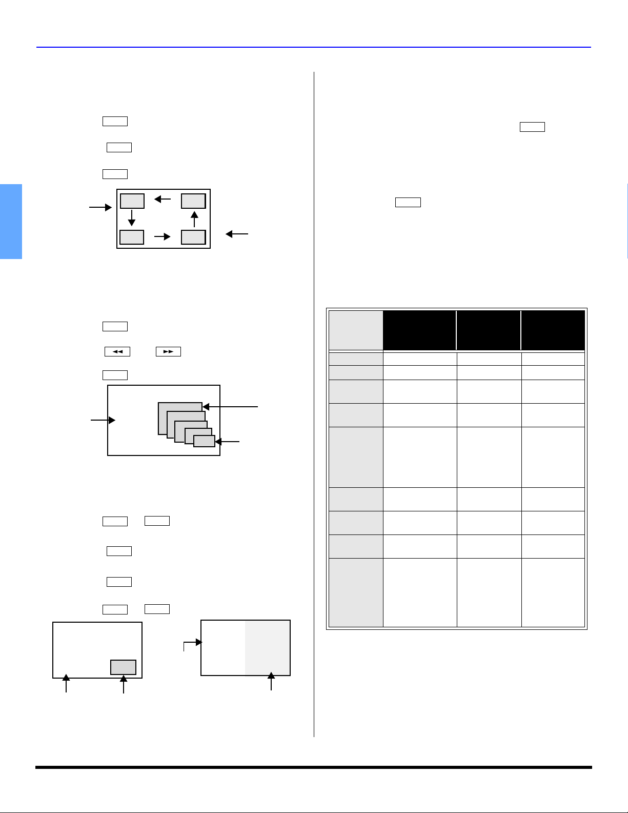
Move Button (PIP only)
This feature is used to move PIP frame to one of four
corners.
Procedure
• Press to display PIP frame.
• Press to position PIP frame to desired corner.
• Press to cancel PIP frame.
Main Picture
PIP
MOVE
PIP
PIP Frame
ENGLISH
PIP MIN and PIP MAX Buttons
While PIP frame is displayed, press PIP MIN or PIP MAX
button to vary the size of PIP frame.
Procedure
• Press to display PIP frame.
• Press or to size PIP frame.
• Press to cancel PIP frame.
Main Picture
Freeze Button (PIP and Split)
This feature is used to stop action in PIP or Split frame.
Procedure
• Press or to display PIP or Split frame
• Press to stop PIP or Split frame action.
• Press again to continue action.
• Press or to cancel PIP frame.
PIP
PIP MIN PIP MAX
PIP
PIP
FREEZE
TV/VCR
FREEZE
TV/VCR
PIP
SPLIT
SPLIT
MIN
MAX
Main Picture Freeze Feature
This feature is used to stop action of the Main Picture and
display it on a Split or PIP freeze frame.
Procedure
FREEZE
TV/VCR
• To stop action for Main picture, press while
PIP or Split frame is not displayed.
• Main Picture freeze will be displayed in a PIP or Split
frame, depending on the selection in the Freeze menu
located in Picture Other ADJ. section (refer to page 20).
FREEZE
TV/VCR
• Press again to cancel Main Picture freeze
frame.
Note: While Main Picture freeze frame is displayed, only
MOVE button is active for PIP, all other PIP and Split
buttons have no effect (see chart).
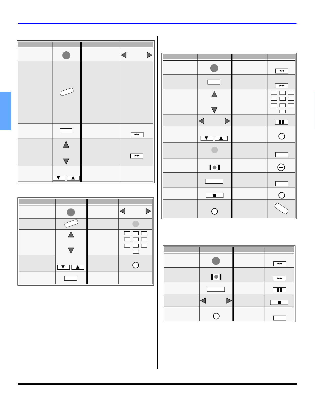
PIP, Split and Freeze Mode Buttons Operational chart
This chart indicates the buttons that are operational with
PIP, Split or Main Picture Freeze mode.
REMOTE
BUTTONS
PIP MODE SPLIT MODE
PIP MIN Size Smaller No Effect No Effect
PIP MAX Size Larger No Effect No Effect
FREEZE
PIP CH
SEARCH
PIP
SPLIT
MOVE
Freeze PIP
frame
Change
Channel
Displays
Search Frame
(not available
when Main
picture is
digital)
Delete PIP
Frame
Displays Split
Frame
Move PIP
Frame
Freeze Split
Frame
Change
Channel
Displays
Search frame
(not available
when Main
picture is
digital)
Displays PIP
frame
Delete Split
frame
No Effect
Swap with
SWAP
Swap with Main
Picture (not
available when
main picture is
digital channel)
Main Picture
(not available
when main
picture is
digital
channel)
MAIN
PICTURE
FREEZE
MODE
Display or
Delete
No Effect
No Effect
No Effect
No Effect
Move PIP
Frame
No Effect
Main Picture
Main Picture
PIP freeze frame
Note: Audio is from Main Picture only.
12 z
Split freeze frame
SPECIAL FEATURES OF THE HIGH DEFINITION PROJECTION TELEVISION
Special Features of the High Definition Projection Television
Channel and Program Tuning
Channel and Program tuning in digital television is different from
current conventional television. In DTV, multiple programs can
exist within a single 6MHZ channel. These channels behave as
sub-channels within a single channel. When tuning to a digital
channel, the HDTV Projection Television will also tune to a
program. The HDTV Projection Television will indicate the channel
and program using the on-screen Channel Banner display.
Note: In order to select channels properly, Auto Scan must be
performed (refer to page 27).
Tuning digital and analog channels
You can tune the digital and analog channels in the following
ways:
Direct tuning (0 - 9 keys) - using the numeric keys on the
Remote control to directly input the Channel number. If
necessary, use the button to enter the program number of
the digital channel.
Channel Up/Down Tuning (CH or CH buttons) - Tunes
to the next or previous available channel or program. The
Channel Up/Down tuning depends upon the surfing mode
(see pg. 21) you have set in the Channel menu.
Rapid Tuning (R-TUNE) - Switches between the last two
channels or programs.
Direct Tuning Method
Follow the procedure below to directly enter the channel number
using the Remote Control numeric keys.
Procedure
• Press the numeric keys on the Remote Control to enter
the Channel number. Press OK button.
• If tuning a digital channel and your channel contains
more than one program, press the button and enter
the program # (1, 2, 3 etc.) using the numeric keys.
Press OK button. The following is an example of tuning
to channel 15-1.
Step Action
1Press 1 1
2Press 5 15
3
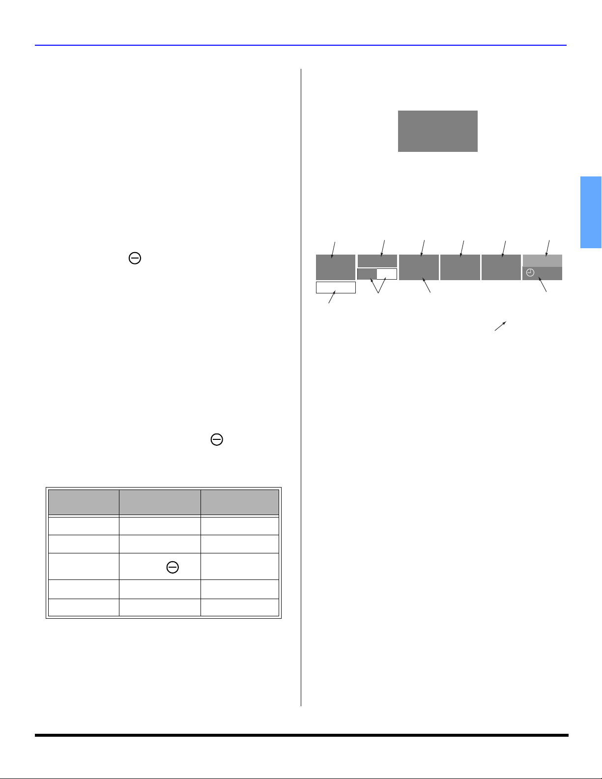
Direct Tuning Example
Channel Banner
Press
Display
15-
Channel Banner: Minimized
The minimized Channel Banner will display the antenna input,
channel number, and the station identification (if available).
A: 15-1
KPBS-HD
Channel Banner: Maximized
Press the RECALL button to display the maximized channel
banner. While the channel banner is displayed, you can add the
channel to Favorite channel list or delete the channel from the
Favorite channel list.
Antenna designation,
Channel and program #
and Station identifier
A: 15-1
KPBS - HD
Add FAV
Add FAV or
Del FAV button
Add Fav / Del Fav feature
This feature lets you add channels to Favorite channel list or
delete channels from Favorite channel list.
Procedure
• Tune the desired the channel to be added or deleted.
• Press the RECALL button to display the Channel
Banner.
• Press the OK button to execute your choice.
Emergency Alert System (EAS) Forced Tuning
If a CableCARD™ module is installed, the cable MSO (multiple
system owner/operator) may provide an Emergency Alert System
message. These messages are intended to alert the general
public of important local or national emergency situations. In the
event of receipt of one of these messages, the HDTV Projection
Television shall immediately tune to the channel as directed by the
EAS message. If the channel has blocked using the parental
control, the parental blocking has priority over the forced tune.
Rating
indication
TV-G
SAPCC
Closed Caption and
SAP indication
Signal Format
1080i
FULL
Program Aspect
Picture mode
setting
VIVID
Audio Track of
digital channel
PIP/SPLIT CH# or
Input information
HDMI
Audio Track 1 of 1 (English)
Clock
12:30 pm
30
Time remaining
in Sleep Timer
ENGLISH
4Press 1 15-1
5 Press OK 15-1
The HDTV Projection Television will tune to channel 15-1.
13 z

SPECIAL REMOTE BUTTONS
Special Remote Buttons
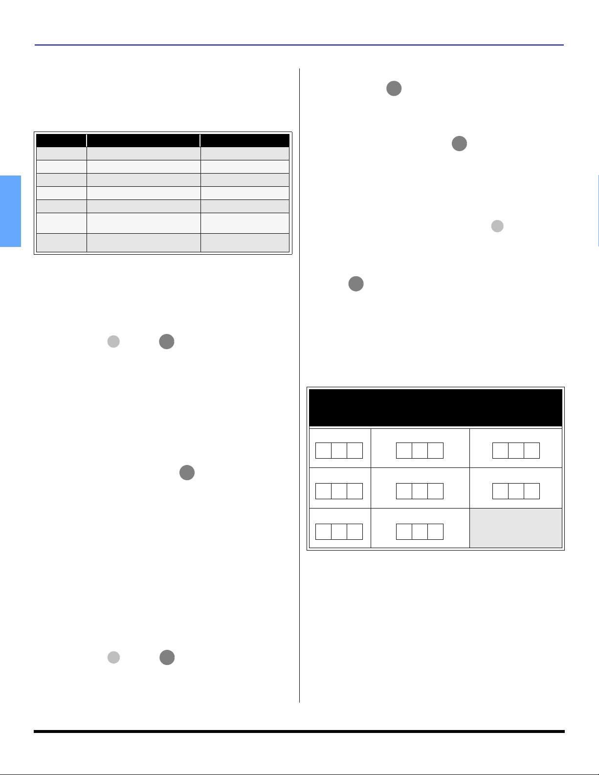
ASPECT Button
Customer Options depending on Input Signal Format
INPUT
SIGNAL
DISPLAY ON SCREEN
1080i 16:9 only No options
480p (16:9) Default to 16:9
480p (4:3) Default to FULL mode.
480i Default to JUST mode
ASPECT BUTTON
OPTIONS
4:3, Full or Zoom (see
below)
4:3, Full or Zoom (see
below)
4:3, Full, Just or
Zoom (see below)
The ASPECT button on the remote control lets you choose
one of four display modes, depending on the formats of the
received signal and your preferences.
ENGLISH
Input Signal
480i or 480p
Input Signal
480i or 480p
ASPECT
4:3
ASPECT
ZOOM
Image on
16:9 Screen Size
4
Image on
16:9 Screen Size
16
This will display a 4:3 picture
at its standard 4:3 size with
gray side bars. (Not
recommended for viewing
4:3 pictures as it may create
3
a permanent image on
screen if displayed for a
prolonged period of time.)
This will expand the 4:3
picture uniformly (width and
height) to full screen width
and then reposition the
picture vertically.
9
(Recommended for letterbox
pictures.)
BBE Button
Press this button to turn BBE VIVA 3D sound feature (available on
PT-53TWD64) or BBE sound feature (available on PT-47XD64
and PT-53XD64) On or Off.
SAP Button
Press this button to select the next audio track (if available) when
receiving a digital channel.
Audio Track 1 of 1 (English)
In analog mode, press this button to cycle through different audio
modes. For example:
• If receiving STEREO, SAP and MONO or receiving
STEREO and MONO only, pressing SAP button,
will toggle the audio as follows:
STEREO SAP MONO
PROG button
When tuning digital channel, press the button to enter the
minor number in a compound channel number.
PROG
MENU button
Press to display the Main menu or return one step backward in
menus.
RECALL button
Press this button to display or remove the channel banner.
R-TUNE Button
Input Signal
480i or 480p
Input Signal
480i
ASPECT
FULL
ASPECT
JUST
Image on
16:9 Screen Size
16
Image on
16:9 Screen Size
16
This will show picture at full
screen size. (Recommended
for anamorphic pictures.)
9
This will stretch the right and
left edges of a 4:3 picture to
fill the screen, The center of
the screen will have aspect
correction applied. The size
9
of the picture will depend on
the original signal.
(Recommended for regular
TV viewing.)
14 z
REMOTE CONTROL OPERATION
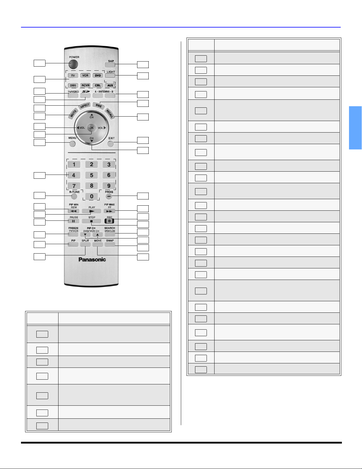
Remote Control Operation
1
2
3
4
5
6
7
8
9
10
11
12
13
14
15
16
17
EUR7627Z10
BUTTON
NUMBER
1
2
3
4
Note: The ON/OFF indicator LED (red) will be lit
Press to select (Component 1or 2), (HDMI),
(Video 1, 2, 3 or 4) input mode or TV mode.
Also press while Photo Viewer™ is displayed to
access Photo Viewer™ set up menu.
Press to select picture size (ratio) to match
5
6
7
Also used for Photo Viewer™ to change aspect
Press to mute sound. Press to display and
Press to adjust TV sound and navigate in
DESCRIPTION
Press to turn ON and OFF.
when set is on.
Press to select remote operation.
Press to access Photo Viewer™.
programming format.
of the image on-screen.
cancel CC (Closed Caption).
menus.
BUTTON
NUMBER
8
18
19
20
21
22
23
24
25
26
27
28
29
30
31
32
9
10
11
12
13
14
15
16
17
18
19
20
21
22
23
24
25
Press to choose menu and sub-menu entry.
Press to display Main Menu or return one step
Press numeric keypad to select any channel or press to
Press to switch to previously viewed channel or input
PIP MIN - While remote is in TV mode, press to
REW - While remote is in VCR or DVD mode, press to
While remote is in VCR or DVD mode, press to play.
While remote is in VCR or DVD mode, press to
FREEZE - While in TV mode, press to stop action in
In analog mode, press to access audio modes (Stereo,
SAP or Mono). In digital mode, press to access next
Press to switch to (A or B) RF antenna input.
Press to display or delete Channel banner.
Press to change channels and navigate in menus.
Press after entering major channel numbers to enter
PIP MAX - While in TV mode, press to increase the PIP
26
FF - While in VCR or DVD mode, press to fast
DESCRIPTION
backward in menus.
enter alphanumeric input in menus.
mode.
decrease the PIP size.
rewind.
pause.
the PIP or Split frame.
TV/VCR - Press to switch to TV or VCR.
Press to display or delete PIP frame.
Press to display or delete Split frame.
audio track.
Press to illuminate remote buttons.
Press to turn BBE OFF or ON.
Press to exit menus.
minor (-) channel numbers.
size.
ENGLISH
forward.
27
28
While remote is in VCR mode, press to record.
While remote is in VCR or DVD mode, press to stop.
SEARCH - Press to scan available channels in
search frames. Press again to delete search frames.
29
30
31
32
OPEN/CLOSE - Press to open or close DVD tray.
Press to change channels for PIP or VCR.
Press to swap Main picture with PIP or Split frame.
While PIP frame is displayed, press to move to one
of four corners.
15 z
REMOTE CONTROL OPERATION
R
R
R
R
Programming The Remote Control
The Universal Remote Control can be programmed to
operate many manufacturers’ components, using the
component function buttons for VCR, DVD, DBS, RCVR or
AUX. Follow the procedures for programming your Remote
Control with or without a code for the component.
Device Operates Default
TV
VCR
DVD/CD
DBS
RCVR
CBL
ENGLISH
AUX
Note: Determine the manufacturer of the component and look
in the table for the code (found on pages 17~18).
TV (Panasonic Only) Panasonic Code
VCR (Preset) Panasonic Code
DVD and CD (Preset) Panasonic Code
DBS STB & CBL STB (Preset) Panasonic DBS Code
Audio Receiver (Preset) Panasonic RCVR Code
Cable (Preset)
Personal Video Recorders,
Cassette and VCR2
Panasonic CABLE
Code
Panasonic Personal
Video Recorder Code
Procedure
1. Confirm that the external component is plugged and
operating.
2. Turn the component off.
3. Press and together, for at least 5
OK
seconds. After 5 seconds, the illuminated mode
(component) buttons will begin to flash. Release the OK
and POWER buttons.
4. Press appropriate component button on the Remote
Control VCR, DVD (CD), DBS, RCVR, CBL or AUX
(PVR or VCR2). The component button will illuminate
steadily and all others will go out.
5. Enter the 3-digit component code using the Remote
Control numeric keypad (0 ~ 9 buttons). The component
button will blink twice.
6. Press the Remote Control to test the component.
If the procedure was successful, the component will
turn on and the component key will blink twice and then
go out.
Note: If the component does not operate with the Remote
Control, repeat steps 3 through 6 using another code.
(Some brands have multiple codes). If an incorrect code
is entered, or if the procedure takes longer than 30
seconds, the programming will fail.
POWE
POWE
Programming Without A Code
This procedure searches all codes and is called the
“sequence method.”
1. Confirm that the external component is plugged in and
on.
2. Turn the component off.
3. Press and
OK
seconds. After 5 seconds, the illuminated mode
(component) buttons will begin to flash. Release the OK
and POWER buttons.
POWE
together, for at least 5
4. Press appropriate component button on the Remote
Control.
POWER
5. Press the button to set the remote control into the
step and set mode.
6. Point the remote control towards the component.
7. Press VOL (the mode key will blink three times), then
POWE
press the Remote Control to test the component.
Continue this process until the proper code is found. If
the procedure was successful, the component will turn
on.
Note: Each time you press the VOL button, make sure that
the component key blinks twice before pressing the
POWER button.
8. Once the device responds, press to store the
OK
code. The mode (component) button will blink twice.
Note: It may take many attempts before the correct code
is found. If you miss a code, press VOL, then press the
POWER
button to test the component.
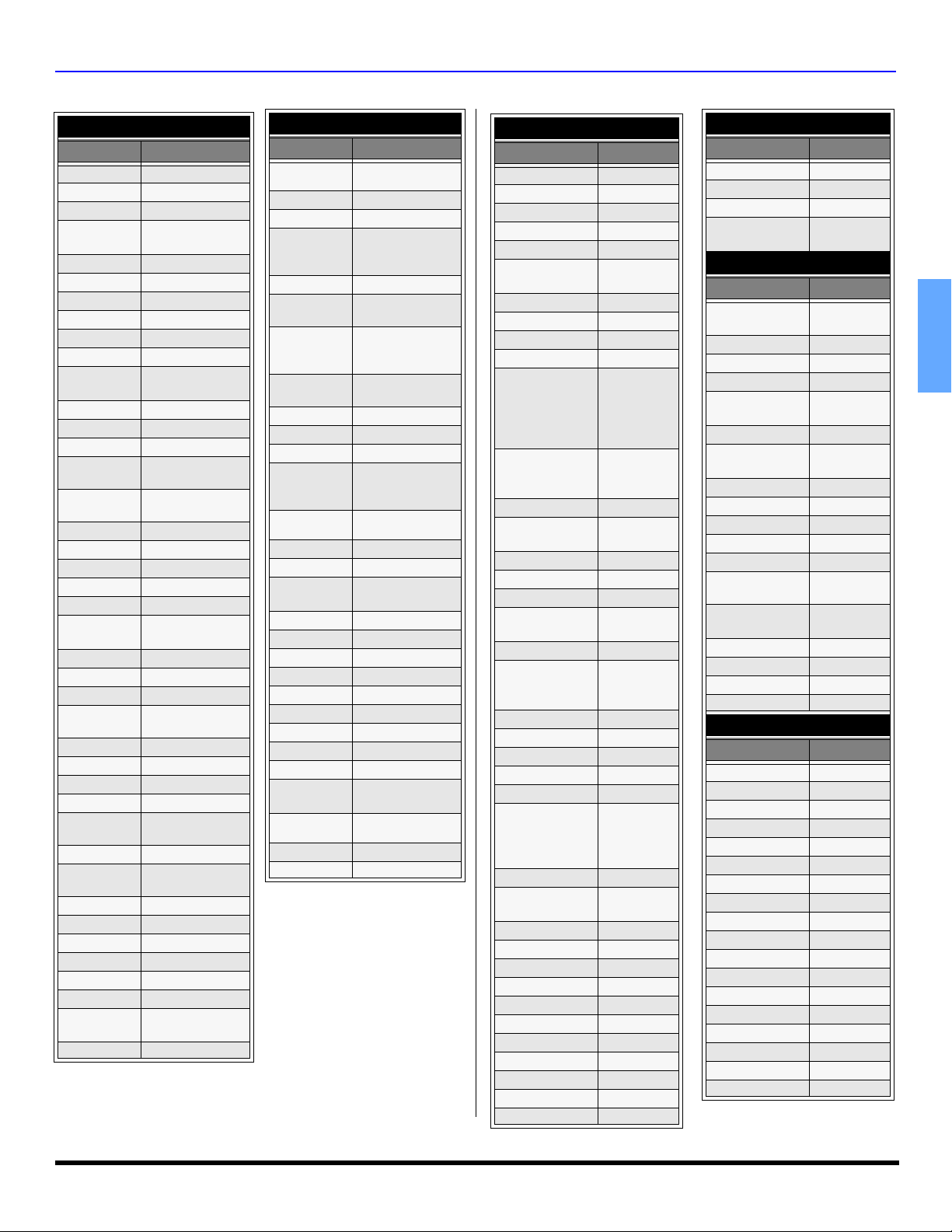
Component Codes
The Universal Remote Control is capable of operating
many component brands after entering a code. Some
components may not operate because the codes are not
available due to limited memory. The Universal Remote
Control does not control all features found in each model.
Write the code numbers from tables in this space.
This will serve as a reference if you need to program
your Remote Control.
VCR DVD DVD (CD)
DBS RECEIVER CABLE
AUX (PVR) AUX (VCR2)
16 z
REMOTE CONTROL OPERATION
Codes For VCR
Brand Code
Admiral
Aiwa
Akai
Audio
Dynamic
Bell & Howell
Broksonic
Canon
CCE
335
332
314, 315, 316, 329
311, 339
305, 313
320, 326
323, 325
343
Citizen 306
Craig
Curtis
Mathes
Daewoo
DBX
Dimensia
Emerson
Fisher
Funai
GE
Goldstar
Gradiente
Hitachi
Instant
Replay
Jensen
JVC
Kenwood
LXI
Magnavox
Marantz
Marta
Memorex
MGA
Minolta
Mitsubishi
Multitech
NEC
Olympic
Optimus
Orion
Panasonic
Penney
Pentax
305, 306, 329
324, 345
301, 324, 343
310, 311, 339
345
303, 319, 320, 325,
326, 343
305, 307, 308, 309,
313
320, 326, 334
324, 333, 345
306
334
300, 323, 345
323, 324
339
310, 311, 334, 339
306, 310, 311, 339
300, 305, 306, 307,
308, 309
323, 324, 331
310, 311, 339
306
309, 324
338, 340, 341, 347,
348
300, 345
338, 340, 341, 347,
348
304, 347
310, 311, 334, 339
323, 324
306, 321, 328, 335
320, 326
321, 322, 323, 324
300, 305, 310, 311,
324, 339, 345
300, 311, 345
Codes For VCR (Contd.)
Brand Code
Philco
Philips
Pioneer
Proscan
Quasar
Radio Shack
RCA
Realistic
Samsung
Sansui
Sanyo
Scott
Sears
Sharp
Shintom
Signature
2000
Singer
Sony
Sylvania
Ta sh ir o
Tatung
Teac
Technics
Te kn ik a
To sh ib a
Vec tor
Research
Wards
Yamaha
Zenith
320, 323, 324, 326,
331, 343
323, 324, 331
323
300, 301, 302, 323,
324, 331, 333, 345,
346
321, 322, 323, 324
305, 309, 324, 333,
336, 340
300, 301, 302, 323,
324, 331, 333, 345,
346
305, 309, 324, 336,
340
302, 304, 333
320, 326, 339, 352
305, 309, 313
301, 302, 304, 309,
320, 326, 338, 340,
347, 348
300, 305, 306, 307,
308
335, 336
317
335
337
328, 329, 330
323, 324, 331
306
310, 311, 339
310, 311, 339
321, 322, 323, 324
324
301, 346
311
306, 309, 335, 336,
344
305, 310, 311, 339
306,344
Codes For Cable Box
Brand Code
ABC 124
Archer 125, 132
Cableview 105, 132
Citizen 105, 122
Curtis 112, 113
Diamond
124, 125,
132
Eagle 129
Eastern 134
GCbrand 105, 132
Gemini 122
111, 119,
General
Instrument/
Jerrold
120, 121,
122, 124,
125, 126,
127
112, 118,
Hamlin
140, 141,
142, 145
Hitachi 103, 124
Macom
Magnavox
103, 104,
105
133
Memorex 130
Movietime 105, 132
Oak
102, 137,
139
Panasonic 109, 110, 114
106, 107,
Philips
128, 129,
130
Pioneer 101, 116
Pulsar 105, 132
Puser 132
RCA 115
Realistic 132
112, 118,
Regal
140, 141,
142, 145,
149
Regency 134
Rembrant
105, 132,
137
Samsung 105
Scientific Atlanta 111, 112, 113
Slmark 101, 105
Sprucer 105, 110
Stargate 105, 110
Te le vi ew 101, 105
Texscan 144
To co m 135
To sh ib a 104
Unika 125, 232
Universal 122, 132
Codes For Cable Box (Contd.)
Brand Code
Videoway 106
Viewstar 129, 130
Zenith 100, 117
Zenith/.Drake
Satellite
100
Codes For DBS
Brand Code
Dish Network
105, 115, 116
(Echostar)
Echostar 105
Express VU 105, 115
G. E . 106
G.I. (General
108
Instrument)
Gradiente 114
Hitachi 103, 111,
112
HNS (Hughes) 103
Magnavox 101, 102
Panasonic 104
Philips 101, 102
Primestar 108
Proscan
106, 109, 110,
113
RCA 106, 109,
110, 113
Sony 107
Star Choice
103, 108
To sh ib a 100
Uniden 101, 102
Codes For DVD
Brand Code
Denon 100
Ferguson 101
JVC 109
Mitsubishi 105
Nordmende 101
Panasonic 100
Philips 103
Pioneer 102
RCA 101
Saba 101
Samsung 110
Sharp 108
Sony 104
Te ch n ic s 100
Thomson 101
To sh ib a 103
Yamaha 100
Zenith 107
ENGLISH
17 z
REMOTE CONTROL OPERATION
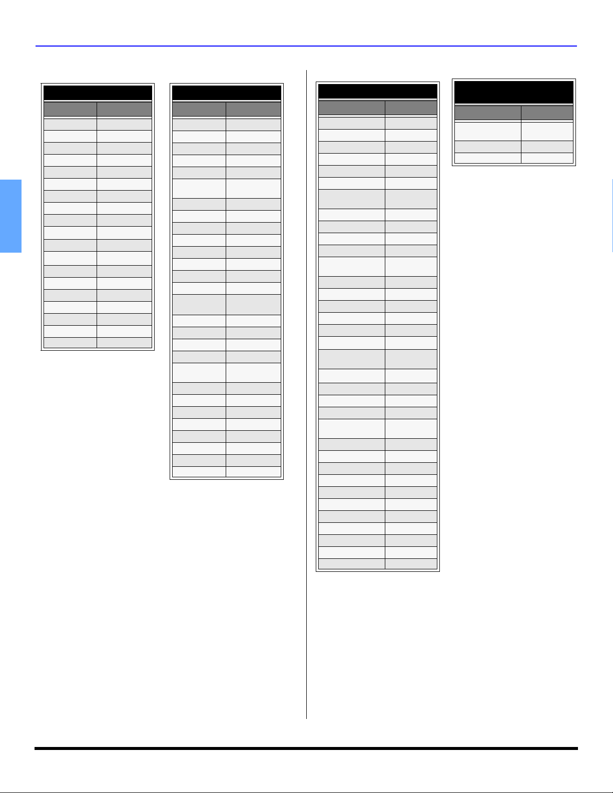
Component Codes (Cont.)
Codes For Cassette Decks
Brand Code
Aiwa
Denon 231
Fisher 203
Jensen 214
JVC 229, 230
Kenwood 200, 207
Marantz 202
Nakamichi 205
Onkyo 208, 209, 213
Panasonic 216, 218
ENGLISH
Philips 222
Pioneer 204
RCA 226, 227, 228
Sansui 205, 210
Sharp 231
Sony 219, 220
Te ac 210, 211, 215
Technics 216, 218
Yam aha 201, 202
223, 224, 225
Codes For Receivers
Brand Code
Admiral 120
Aiwa 125, 126
Denon 134, 135, 136
Fisher 104
Garrard 113
Harman
Kardon
Jensen 129
JVC 132, 133
Kenwood 100, 108
Magnavox 127
Marantz 124
Mclntosh 11 6
Nakamichi 106
Onkyo 109, 114
Optimus
Panasonic 118, 119, 121
Philips 123
Pioneer 105, 107
Quasar 118, 119, 121
RCA
Sansui 103, 111, 139
Sharp 134, 137
Sony 122
Soundesign 138
Te ac 111, 112 , 11 3
Technics 118, 119, 121
Victor 132, 133
Yam aha 101, 102
115, 123
103, 127, 130,
131
103, 105, 127,
130, 131
Codes For CD Players
Brand Code
Admiral 226
Aiwa 233, 235
Carver 229
Denon 242
Emerson 239
Fisher 205
Harman/Kardon
Hitachi 207
Jensen 234
JVC 240, 241, 245
Kardon 223
Kenwood
LXI/Sears 236
Magnavox 229, 232
Marantz 229
McIntosh 221
Nakamichi 210
Onkyo 214, 215
Optimus
Panasonic 224, 225, 227
Philips 229, 230
Pioneer 208
Quasar 224, 225, 227
RCA
Sansui 210, 246
Sanyo 205
Scott 210, 246
Sharp 242, 243
Sherwood 220
Sony 228
Soundesign 244
Te ac 212, 216, 218
Technics 224, 225, 227
Victor 240, 241, 245
Yam aha 202, 203, 204
219, 220,
221, 223
200, 201, 211,
245
208, 218,
220, 222
231, 237,
238, 247
Codes For Personal Video
Recorders
Brand Code
Panasonic Replay
TV
Philips Tivo 102
Sony Tivo 101
100
18 z

Operating Components with Remote Control
POWER
Note: Refer to page 16 for programming Remote Control
procedure.
Operating a VCR
Program the remote control to use with VCR.
TO DO THIS... PRESS TO DO THIS... PRESS
Turn on/off
Select TV Input
mode for VCR
Change Channels
up/down
Change Channels
up/down
Record
Play
Stop
TV/VIDEO
CH
CH
PIP CH
DVD/VCR CH
REC
PLAY
STOP
Rewind the
Tape
Fast Forward
Select a Channel
Pause
Change to TV or
VCR Mode
On screen VCR
Display
PIP MIN
REW
PIP MAX
FF
1 2 3
4 5 6
7 8 9
0
PAU SE
FREEZE
TV/VCR
R
E
C
A
L
L
REMOTE CONTROL OPERATION
Operating a DBS
Program the remote control to use with DBS.
TO DO THIS...
Turn on/off
STB Audio track
Navigation
up/down
STB Change
Channels up/down
STB Aspect
STB Menu
STB Exit
STB program info STB jump
PRESS TO DO THIS... PRESS
POWER
SAP
CH
CH
PIP CH
DVD/VCR CH
E
P
S
A
MENU
EXIT
R
E
C
A
L
T
C
L
Navigation
left/right
STB Action
Select a
Channel
Previous
Channel
STB select
dash channel
STB search
STB M. guide
VOL VOL
OK
1 2 3
4 5 6
7 8 9
0
R-TUNE
PROG
SEARCH
OPEN/CLOSE
PIP
MOVE
ENGLISH
Operating a DVD
Program the remote control to use with DVD
TO DO THIS... PRESS TO DO THIS... PRESS
Turn on/off Skip search<<
POWER
Navigation
left/right
Navigation
up/down
Ch -/+
Record
Play
Stop
Open/Close
Select TV input
for DVD
VOL VOL
CH
CH
PIP CH
DVD/VCR CH
REC
PLAY
STOP
SEARCH
OPEN/CLOSE
TV/VIDEO
Skip search>>
Select chapter
Still/Pause
Select
DVD Display
Menu
Title
PIP MIN
REW
PIP MAX
FF
1 2 3
4 5 6
7 8 9
PAU SE
OK
R
E
C
MENU
R-TUNE
STB FAV
STB Record
SPLIT
REC
Select TV
input for DBS
Change to TV
or SAT Mode
TV/VIDEO
FREEZE
TV/VCR
Operating a CD
Program the remote control to use with CD.
TO DO THIS...
Turn on/off Play
0
A
L
L
Time format Select Tracks
Next/previous
track
Random / repeat
Search FF
Stop
PRESS TO DO THIS... PRESS
POWER
R
E
C
A
L
L
CH
Search Rew
1 2 3
4 5 6
7 8 9
PIP MIN
CH
PIP CH
DVD/VCR CH
PIP MAX
FF
STOP
Next disk
Still/pause
Open/Close
R-TUNE
PAU SE
SEARCH
OPEN/CLOSE
PLAY
0
REW
19 z
REMOTE CONTROL OPERATION
Operating a Receiver
Program the remote control to operate audio receiver.
TO DO THIS... PRESS TO DO THIS... PRESS
Turn on/off Vol ume +/-
Audio Mute
ENGLISH
Input Switch Surround -
Tuner +/- Surround +
Center-/+
Operating a CABLE BOX
Program the remote control to use with Cable Box.
TO DO THIS... PRESS TO DO THIS... PRESS
Turn on/off
POWER
E
T
U
M
TV/VIDEO
CH
CH
PIP CH
DVD/VCR CH
POWER
To select AV input
or Components
Vol ume
up/down
VOL VOL
Press Remote
numeric keypad
AVI P r es s 1
AV2 P res s 2
AV3 P res s 3
AV4 P res s 4
CD Press 5
TUNER Press 6
PHONO Press 7
TAPE Press 8
AUX Press 9
PIP MIN
REW
PIP MAX
FF
VOL VOL
Operating a PVR (Personal Video Recorder)
To operate a PVR, the remote control must be in AUX
mode and be programmed with the appropriate code for
your equipment.
TO DO THIS... PRESS TO DO THIS... PRESS
Turn on/off Rewind
POWER
Select TV/VCR Fast Forward
PVR up/down Select a Channel
PVR left/right Pause
Change
Channels
TV/VIDEO
CH
CH
VOL VOL
PIP CH
DVD/VCR CH
Replay zones
up/down
PVR select Instant replay
Record
Play
Stop
Menu
OK
REC
PLAY
STOP
MENU
Return to live
Quick skip
Exit
Enter
PIP MIN
REW
PIP MAX
FF
1 2 3
4 5 6
7 8 9
0
PAUSE
R-TUNE
FREEZE
TV/VCR
PROG
SEARCH
OPEN/CLOSE
EXIT
R
E
C
A
L
L
E
Audio Mute Enter
Change
Channels
up/down
Change Channels
up/down
Input Switch
T
U
M
CH
CH
PIP CH
DVD/VCR CH
TV/VIDEO
Select a
Channel
Previous
Channel
OK
1 2 3
4 5 6
7 8 9
0
R-TUNE
Operating a Cassette Deck
To operate a cassette deck, the remote control must be in
AUX mode and be programmed with the appropriate code
for your equipment.
TO DO THIS... PRESS TO DO THIS... PRESS
Turn on/off Rewind
POWER
Record
Play
Receiver Volume
Up/Down
Deck A/B
REC
PLAY
VOL VOL
R-TUNE
Fast Forward
Pause
Stop
Open/Close
PIP MIN
REW
PIP MAX
FF
PAUSE
STOP
SEARCH
OPEN/CLOSE
20 z
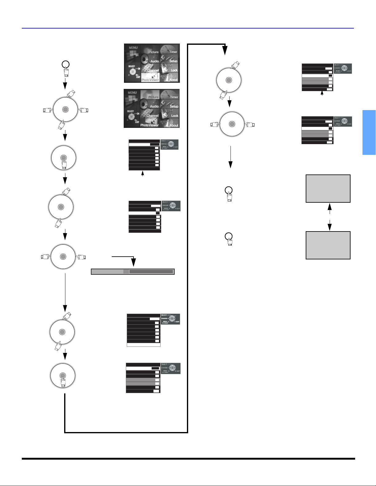
Basic Menu Navigation
BASIC MENU NAVIGATION
Press
MENU
to display the
Main Menu.
CH
VOL VOL
OK
Press
Press
Press to select desired
Press
VOL VOL
CH
VOL VOL
OK
CH
VOL VOL
OK
CH
CH
OK
CH
CH
CH
to select
the desired
icon.
to enter the submenu field.
sub-menu
feature.
to adjust or set desired sub-menu
feature.
Tint 31
Picture
Pic Mode
Color
Tint
Brightness
Picture
Sharpness
Normal
Other Adjust
Vivid
31
31
31
63
41
Set
sub Menu
Field
Picture
Pic Mode
Color
Tint
Brightness
Picture
Sharpness
Normal
Other Adjust
- - - - - - - - - - - - - - - l - - - - - - - - - - - - - - -
Vivid
31
31
31
63
41
Set
Press to select desired
Press
CH
VOL VOL
OK
CH
VOL VOL
sub-menu.
CH
OK
CH
to adjust or
select desired
sub-menu.
Note: To EXIT menus.
Press
MENUMENU
repeatedly until normal
picture is displayed.
or
Press
EXIT
to return to normal
picture.
Other Adjust
Color Temp
Natural Color
Video NR
3D Y/C Filter
Color Matrix
VM
Freeze
Cool
On
Off
Off
SD
Off
Split
sub sub- Menu
Field
Other Adjust
Color Temp
Natural Color
Video NR
3D Y/C Filter
Color Matrix
VM
Freeze
Cool
On
On
Off
SD
Off
Split
NORMAL PICTURE
ENGLISH
Note: For sub -menu with OTHER ADJ.
Press to select Other
Press
CH
VOL VOL
OK
CH
CH
VOL VOL
OK
CH
Adj.
to access
Other Adj.
sub-menu.
Picture
Pic Mode
Color
Tint
Brightness
Picture
Sharpness
Normal
Other Adjust
Other Adjust
Color Temp
Natural Color
Video NR
3D Y/C Filter
Color Matrix
VM
Freeze
Vivid
OK
31
31
31
63
41
Set
Cool
On
Off
Off
SD
Off
Split
21 z
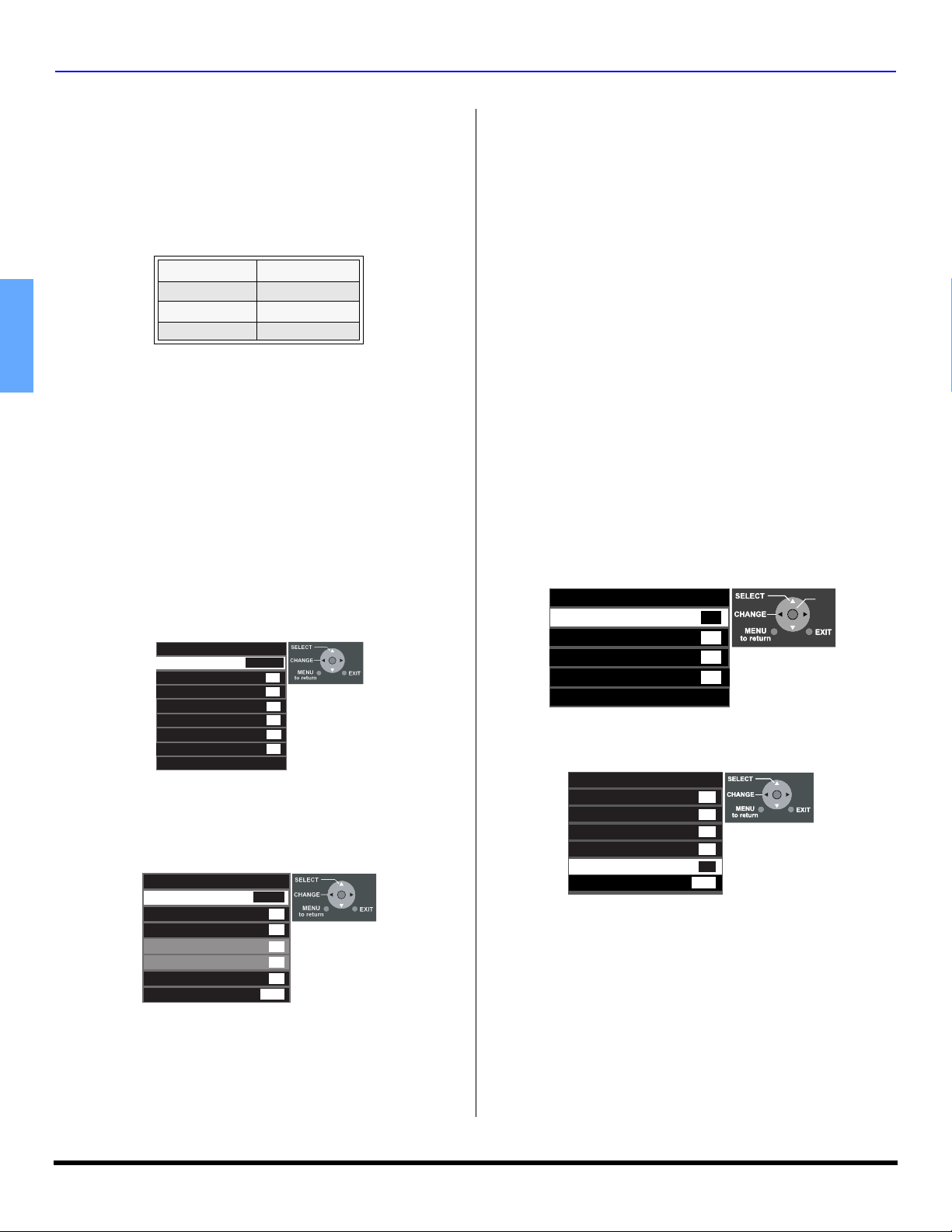
MENU OPERATIONS
Menu Operations
PICTURE
Note: While sub-menu features are highlighted, press VOL
or VOL to adjust or activate.
PIC MODE - Lets you choose one of three pre-set
Picture Modes that best suits the program you are
viewing. Selecting this feature will also affect Color
Temperature setting.
PIC MODE-COLOR TEMP DEFAULT SETTINGS
PIC MODE COLOR TEMP
VIVID COOL
STANDARD NORMAL
CINEMA WA RM
Note: Each mode has its own picture settings (Color, Tint, Brightness,
ENGLISH
COLOR - Adjusts desired color intensity.
TINT - Adjusts natural flesh tones.
BRIGHTNESS - Adjusts dark areas of picture.
PICTURE - Adjusts white areas of picture.
SHARPNESS - Adjusts clarity of outline detail.
NORMAL - Reset each PIC Mode adjustments to
Other Adjust
Highlight OTHER ADJ. and press OK button to display the
sub sub-menu.
Note: While sub sub-menu features are highlighted, press
Picture and Sharpness) and Color Temp. settings.
• VIVID - This is the default mode, It provides
enhanced picture contrast and sharpness for
viewing in a well-lit room.
• STANDARD - Recommended for normal viewing
conditions with subdued room lighting.
• CINEMA - Select this mode for watching movies in
a darkened room. It provides a soft, film-like
picture.
factory default settings.
Picture
Pic Mode
Color
Tint
Brightness
Picture
Sharpness
Normal
Other Adjust
VOL or VOL to select or activate.
Other Adjust
Color Temp
Natural Color
Video NR
3D Y/C Filter
Color Matrix
VM
Freeze
• COLOR TEMP (temperature) - To increase or decrease
WARM (red) and COOL (blue) colors to suit personal
preferences.
• NATURAL COLOR - To increase the color reproduction
range with natural color gradation and highly delicate
hues.
• VIDEO NR - Reduces noise in the channel, commonly
called snow.
Vivid
31
31
31
63
41
Set
Cool
On
Off
Off
SD
Off
Split
• 3D Y/C FILTER - Minimizes noise and cross color in the
picture (not selectable when receiving digital signal).
• COLOR MATRIX - Available only with 480p signal.
Select HD or SD to automatically adjust color
parameters for HD (high definition) and SD (standard
definition). This feature is not selectable when viewing
regular TV (NTSC) program.
Note: When viewing a non-standard DTV signal
format, you can change color parameters
manually for the best picture quality.
• VM (VELOCITY MODULATION)-To increase picture
sharpness and provides crisp white to black transitions
• FREEZE - This feature is used to freeze main picture
and display it in a PIP or SPLIT frame, when the
FREEZE button on the remote control is pressed. Press
FREEZE again to delete frame.
Note: SWAP, SIZE, SEARCH, PIP MIN and PIP MAX buttons are not
functional in this mode.
AUDIO
Note: While sub-menu features are highlighted, press VOL
or VOL to adjust or activate.
BASS - Increase or decrease the bass response.
TREBLE - Increase or decrease the treble response.
BALANCE - Emphasize the left/right speaker volume.
NORMAL - Reset BASS, TREBLE and BALANCE
adjustments to factory default settings.
Audio
Bass
Treble
Balance
Normal
Other Adjust
7
8
31
No
Other Adjust
Note: While sub sub-menu features are highlighted, press VOL
to adjust or activate.
Other Adjust
AI Sound
BBE VIVA
BBE
Surround
Speakers
HDMI In
• AI SOUND - Equalize overall volume levels across all
channels. (AI sound is not available in VIDEO mode).
• BBE VIVA 3D - BBE VIVA provides a musically accurate
natural 3D image with hi-fi sound. The clarity of the
sound is improved by BBE while the width, depth and
height of the sound image are expanded by BBE's
proprietary 3D sound processing. BBE VIVA is
compatible with all TV programs including news, music,
dramas, movies and sports as well as electronic games.
BBE VIVA enhances the surround sound effect, while
maintaining the clarity of dialogue.
Note: BBE VIVA 3D is available in model PT-53TWD64 only.
• BBE
- BBE High Definition Sound restores clarity and
®
presence for better speech intelligibility and musical
realism.
Off
Off
Off
Off
On
Auto
OK
22 z
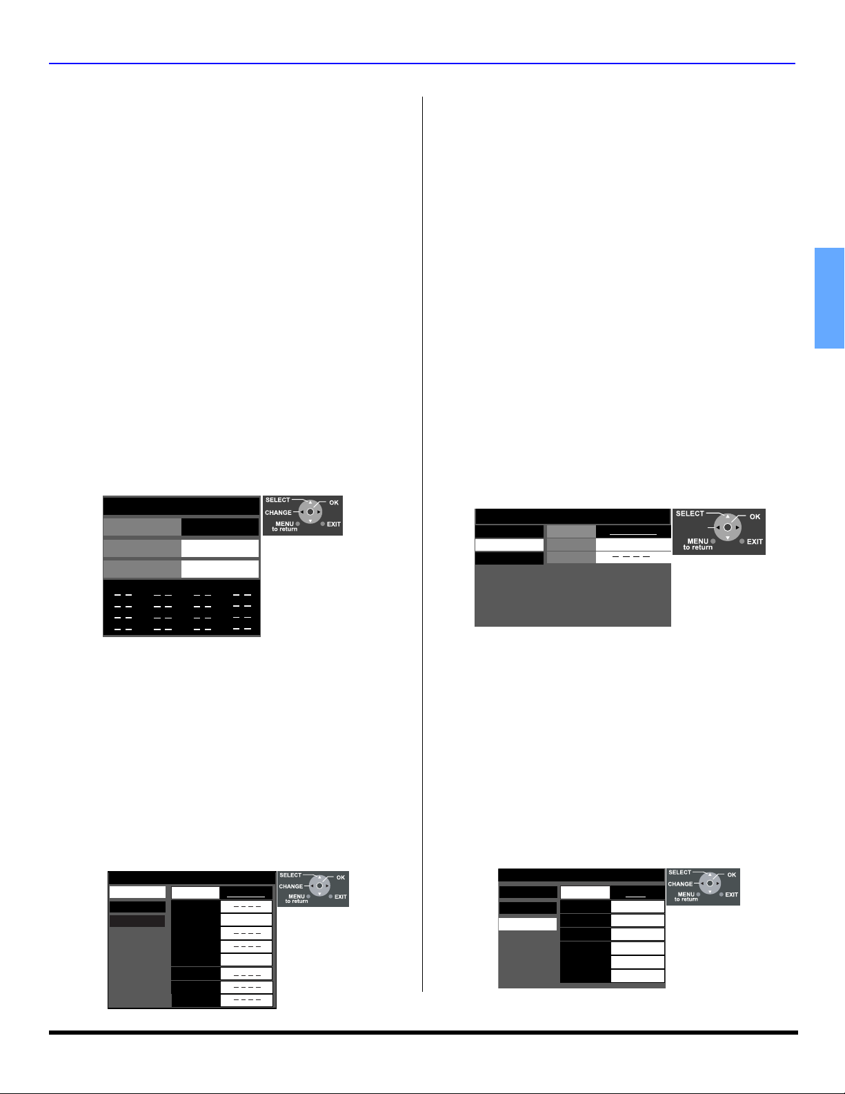
AUDIO (cont.)
Other Adjust (cont.)
• SURROUND - Enhances audio response when listening
to stereo.
• SPEAKERS - This feature is used to turn TV speakers
ON or OFF.
• On - TV speakers operate normally.
• Off - TV speakers off.
• HDMI In - When using HDMI, this feature will let you
switch between Analog Input and Digital Input.
• Auto - Automatically selects Analog / Digital signal.
• Digital - Selects Digital audio signal received via the
HDMI terminal.
• Analog - Selects Analog audio signal received via
the RCA terminals.
CHANNEL
Favorite - Allows you to create Favorite channel list from
Antenna (A) or Antenna (B).
Surf Mode - Select FAVORITE or ALL CHANNELS
with remote control
button.
RF Input - Select Antenna (A) or Antenna (B).
Channel - Use the remote control
select desired channels, then press the OK button to
add. To delete channel, press OK again while channel
number is displayed.
Favorite
Surf Mode
RF Input
Channel
The maximum is 16 favorite channels
VOL or VOL , then press the OK
VOL or VOL to
Favorites
_______
Antenna (A)
A 1
MENU OPERATIONS
Note: To delete a channel number, while highlighted
press VOL repeatedly until all numbers are
removed, then press OK button.
Manual Labels - To enter numbers and captions
manually.
Procedure
• Press OK button while Manual Labels is selected to
select RF Input, then press VOL or VOL to
select Antenna (A) or Antenna (B).
Note: Only input with signal will be selectable.
•Press OK button to underline your selection.
• Press CH to select Channel, then press VOL
or VOL to select available channel number.
• Press CH to select CAPTION.
• Press VOL to select first character position, then
press CH or CH to select character (refer to
your local TV guide for labeling channels).
• Repeat until all characters are added, up to (7)
characters can be added for each channel.
•Press OK button to underline your selection.
Note: To delete the Channel Caption, highlight the first
character and press CH or CH until no character is
displayed. Move to the next character and repeat the
process. After all characters have been deleted, press
OK to enter the choice.
Captions
Preset Labels
Manual Labels
Input Labels
RF input
Channel
Caption
Antenna (A)
15-1
CHANGE
ENGLISH
Captions - To enter preset and manual labels to desired
stations. Also to enter input label to video inputs.
Preset Labels - To enter channel numbers for popular
TV stations.
Procedure
• Press OK button while Preset Labels is selected to
select RF Input, then press VOL or VOL to
select Antenna (A) or Antenna (B).
Note: Only input with signal will be selectable.
•Press OK button to underline your selection.
• Press CH to select desired preset caption.
• Then use the remote numeric keypad to select
desired channel (refer to your local TV guide).
• Press OK to enter the selection.
Captions
Preset Labels
Manual Labels
Input Labels
RF Input
ABC
CBS
FOX
NBC
PBS
CNN
ESPN
HBO
Antenna A)
12-1
15-1
Input Labels - To label video input connections for
onscreen display.
Procedure
• Press OK button while Input Labels is selected to
select COMPONENT 1, then press VOL or
VOL to select preset INPUT LABEL for
component 1.
• Press OK to underline your selection.
• Press CH to select another input, then repeat
procedure for adding more labels to inputs.
Notes:
• To delete Input labels, select desired input, then
press VOL or VOL until no label is
displayed.
• Press OK button to enter your selection.
Captions
Preset Labels
Manual Labels
Input Labels
Component 1
Component 2
HDMI
Video1
Video2
Video3
Video4
DBS
SKIP
DVD
VCR
23 z

MENU OPERATIONS
Photo Viewer™ Operation
Photo Viewer™ lets you display JPEG images recorded by digital
camera on SD card or other types of memory card when it is
inserted in the proper card slot.
SD CARD
SD Card slot
PCMCIA card slot
Notes:
• Photo Viewer™ can only show still images recorded by
Digital Still Camera with DCF and EXIF standard JPEG
file.
• Other types of Memory cards can be inserted into the
PCMCIA card slot by using the appropriate Card
ENGLISH
adaptor.
• Memory cards are not supplied with this television.
Compatible memory cards that can be viewed with
Photo Viewer™
Card type Maximum Size
SD, MMC (Multi Media Card),
Smart Media*, Compact Flash*
Memory Stick*, xD-Picture Card*
Flash ATA*, Memory Stick Pro*
*These cards require standard
PCMCIA adaptor. (Some PC card
adaptor will not be compatible).
Note: Photo Viewer™ is not
compatible with card type hard disk
(Micro Drive, Mobile type hard
disk, etc.)
SD - 512MB, MMC - 64MB
xD-Picture Card - 128MB
Memory Stick Pro - 1GB
Inserting and Removing SD or PCMCIA card
WARNING: As with any small object, SD cards can be
swallowed by young children. Do not allow
children to handle the SD card. Please remove
the SD card immediately after use.
Procedure
SD card - Push in the SD card into the SD card slot until it is
clicked in. Press again on the card to remove it.
PCMCIA card - Push in the card firmly until it is seated. To
release the card, press the release button on the right side of
the card slot. Before inserting or removing the PCMCIA card,
make sure that the TV is turned Off. Otherwise, it may
damage the unit. Do not insert anything other than the
PCMCIA card.
Information Regarding memory cards
• Memory cards must be formatted with FAT12 or FAT16 in
order to be viewed on TV. If the card is not formatted, it may
cause incompatibility with certain memory card adaptors. If
this happens, reformat the card using your digital camera.
Refer to your camera manual for more information.
Note: Reformatting the card will erase the images stored in
it.
Basic Operation
Insert either the SD card or the PCMCIA card into the appropriate
slot. The video disappears from the screen while the Photo
Viewer™ access the information from the card. After accessing
the images from the card, a thumbnail screen is displayed onscreen. Use the navigation keys to select the desired thumbnail
PCMCIA card
eject button
Smart Media - 128MB,
Compact Flash - 1 GB
Memory Stick - 128MB
Flash ATA - 128 MB
and press OK button to display the image on-screen. Use VOL
or VOL to select the previous or next picture. Press EXIT
button to exit Photo Viewer™ mode.
Photo Viewer™ - Thumbnail mode
The thumbnail screen is the initial entry screen from the main
menu. It shows the total number of images on the card, Filename
(folder number and the number of the thumbnail that is
highlighted), the date the picture was taken and the pixel
(resolution) of the picture.
Procedure
• Press MENU button to display the Main menu.
• Highlight Photo Viewer™ Icon using the navigation (Left/
Right/Up/Down) keys.
• Press OK button to display the thumbnail screen.
Note: It may take long time to display the thumbnail if there are lots of
files or if the file size is big.
• Select the desired thumbnail image by using the
Left/Right/Up/Down navigation keys.
• Press OK button to start the Single Picture View mode.
• Change the picture by pressing VOL or VOL keys.
• Rotate the picture if necessary, by using the CH or
CH keys.
Notes:
• Maximum number of folders that can be displayed: 100.
• Maximum file size: 3000. Any folder of files larger than
the specified size, will not be displayed.
• Picture resolution: Compatible in the range 64x64 8192 x 8192 (sub-sampling 4:2:2 or 4:2:0)
• If the image is imported from a PC, it must follow the
EXIF (Exchangeable image file format) 2.0, 2.1, 2.2 in
addition to the DCF (design rule for Camera File system)
format, or it will not be displayed.
• If the JPEG is modified using a PC, it will not be
displayed on TV.
• The Photo Viewer™ cannot display Motion JPEG and
still image not DCF formatted (i.e. TIFF, BMP).
• If the file is partially corrupted, it may be shown in lower
resolution.
• If both SD card and PCMCIA card is inserted at the
same time, SD card has the priority. Otherwise, the card
inserted later will have priority.
• Do not remove the SD card or PCMCIA card while Photo
Viewer™ is accessing the information (when the card
icon is flashing). Such action may damage the memory
card or the unit itself.
24 z

Photo Viewer™ Operations (Cont.)
Photo Viewer™ Setup Menu
This menu allows you to customize features in the Photo
Viewer™ Setup menu.
Procedure
• Highlight Photo Viewer™ icon and press OK button to
display the thumbnail screen.
• Press the SD button on the remote control to display the
Setup screen.
•Use the CH, VOL or VOL keys to navigate in
the setup menu.
100-001 0001/0066
EXIT
Return
5Sec
Left
OK
: 07/04/2002
: 1600 x 2000
Setup Menu
Slide Show Start
Interval
Sequence Order
Repeat OFF
Rotate
Card SD
SELECT
CHANGE
Date
Pixel
Slide Show - Allows you to start the slide show by pressing
the OK button while Start is highlighted. Press OK button to
stop the Slide Show.
Note: When you are in the Slide Show mode, you can change
the Aspect of the image on screen by pressing the
ASPECT button on the remote control.
Interval - Allows you to change the length of time that a slide
is being displayed on screen. Available settings are: 5sec,
10sec, 15sec, 30sec, 60sec, 90sec and 10 minutes.
Sequence - Select either Order or Random.
Repeat - Select Off or On.
Note: After setting Interval, Sequence or Repeat, press CH
button to select Start, then press OK to start the Slide
Show.
Rotate - Allows you to rotate the image.
Zoom - Lets you select the magnification of the Single Slide
display.
Procedure
• While in the Single Slide display mode, press SD button
to display Photo Viewer™ Setup Menu. Zoom option will
be displayed in the Setup Menu.
• Highlight Zoom and press OK button.
• Press VOL or VOL button to select To Fit, x2 or x4.
• Press OK button. To move the image in the picture
frame, press the navigation buttons.
• Press OK to view the slide in normal magnification.
Card - Select either SD or PC when both cards are inserted in
the slots.
MENU OPERATIONS
Following are some of the error messages that may be displayed
on-screen when certain conditions are not met or exceeds the
Photo Viewer™ specifications.
Error condition
When inserting Card
If the JPEG file is corrupted
and cannot be decoded.
If the card is not formatted with
FAT 12 or FAT 16 or if it is not
DCF standard.
If thumbnail and main picture
cannot be shown
Over 3000 image files
Resolution over
If incompatible card is inserted This type of card is not supported.
Photo Viewer™ Troubleshooting
Symptoms Solutions
Cannot read the content of
the card
PC card cannot be ejected
Poor picture quality
Long time to display
Notes:
• If thumbnail screen or a single slide image is displayed
for longer than 10 minutes, Image shift (refer to page 26)
feature will be activated to prevent image retention. The
image on-screen will zoom-in and zoom-out in 4 (four)
steps.To exit this mode, press OK button or select
another slide or press any button.
• During the Slide show, the Image shift feature will
activate if the image is displayed longer than 5 (five)
minutes. The image will be shifted horizontally (left or
right) in minute increments. Image shift feature will not
activate, if it is turned Off.
Error messages
Error messages displayed
No card or Card is not inserted
correctly
This type of image is not supported.
This type of format is not supported.
This icon will appear where
thumbnail image will.
Photo Viewer™ cannot support over
3000 JPEG files.
Photo Viewer™ cannot support over
8192 x 8192 pixels.
A ) No t c o m p at i b l e fo r m a t . Mu s t b e
formatted with FAT 12 or FAT 16.
B) The extension is not “JPG”.
Photo Viewer™ can display EXIF
standard JPEG file, and JPEG
file which is not EXIF standard
cannot be shown.
C) The folders not under DCF
standard.
Push the card all the way in, and
eject.
If the main image cannot be read
(the file is partially corrupted), the
Photo viewer™ will read the
thumbnail. Please confirm the
format of the image.
It will take long time to display, if
there are lots of images or if the file
size is big.
on-screen
ENGLISH
25 z
 Loading...