

Panasonic PT-53TWD63, PT-56TWD63, PT-53WXD63, PT-47WXD63 Operating Instructions Manual
l
High Definition Projection Television
Operating Instructions
TM
DO[°o=v!
DIGITAL
ATSC CERTIFIED *
DIGITAL TELEVISION
I I ....
I
U
PT-47WXD63
PT-53WXD63
PT-53TWD63
PT-56TWD63
%he presenoe of the DTV _-eftfl_tlOll mark iiidlOates that this
prOdLIGtwill SLI_SSfUI|y _reo_lVe digital teJevisio[i tfa[is[lllSSIO[is
that conform to any" and all of the video formats descrub_d ill the
/_.q-SCDigital Television Standard
TQB2AA0474
PRINTED IN USA
IMPRESO EN EE.UU.
30728
The lightning flash with arrow head
within a triangle is intended to tell the
user that parts inside the product are
a risk of electdc shock to persons.
The exclamation point within a triangle
is intended to teU the user that
important operating and servicing
instructions are in the papers with the
appliance
WARNING: To reduce the risk of fire or electric shock do not expose this apparatus to rain or
mo sture and objects fied w th qu ds, such as vases, shou d not be paced on th s
apparatus.
The Class 11insulation symbol (square within a square) indicates that this product has been evaluated
and tested to comply with Class II insulation requirements.
FCC CAUTION: ANY CHANGES OR MODIFICATIONS TO THIS PTV RECEIVER NOT EXPRESSLY
APPROVED BY MATSUSHITA ELECTRIC CORPORATION OF AMERICA COULD CAUSE
HARMFUL INTERFERENCE, WHICH WOULD VOID THE USER'S AUTHORITY TO
OPERATE THIS EQUIPMENT.
WARNING: AS WITH ANY SMALL OBJECT, SD CARDS CAN BE SWALLOWED BY YOUNG CHILDREN. DO]
NOT ALLOW CHILDREN TO HANDLE THE SD CARD.
]
ENVIRONMENTAL NOTICE: THIS PRODUCT UTILIZES CATHODE RAY TUBES (CRT) AND OTHER]
COMPONENTS THAT CONTAIN LEAD. DISPOSAL OF THESE MATERIALSI
MAY BE REGULATED IN YOUR COMMUNITY DUE TO ENVIRONMENTAL|
CONSIDERATIONS. FOR DISPOSAL OR RECYCLING INFORMATION|
PLEASE CONTACT YOUR LOCAL AUTHORITIES, OR THE ELECTRONICS
INDUSTRIES ALLIANCE: <HTTP://WWW.EIAE.ORG.> J
HDMI, the HDMI logo and High Definition Multimedia Interface are
trademarks or registered trademarks of HDMI Licensing LLC.
__:SD Logo is a trademark.
ViVA Manufacturedunder,icensefromBOESound,,no,
I_BE® HD3D Sound Licensed by BBE Sound, Inc. under USP4638258, 4482866, 5510752 and
m_lL_ In05736897 BBE and BBE symbol are registered trademarks of BBE Sound,
High Definition Sound
This product incorporates copyright protection technology that is protected by U.S. patents and other
intellectual property rights. Use of this copyright protection technology must be authorized by
Macrovision Corporation, and is intended for home and other limited viewing uses only unless
otherwise authorized by Macrovision. Reverse engineering or disassembly is prohibited.
U.S. Patents Nos. 4,631,603; 4,577,216; 4,819,098; 4,907,093; 6,381,747; and 6,516,132.
Read these instructions completely before operating television.
Contents are subject to change without notice or obligation.
Copyright 2003 by Matsushita Electric Corporation of America. All rightsreserved.
Unauthorized copyingand distribution is a violation of law.
Information Regarding Convergence
In the projection television, the image is formed by
projecting 3 different color images (red, green and blue)
onto the projection screen. Convergence refers to the
alignment of red, green and blue images on the
projection screen. When these images are properly
aligned (converged), you see a sharp and vibrant color
image. Sometimes, the three images may require
alignment. This is due to the effect of earth's magnetic field
on the projection tubes. Normally, adjustment is not
necessary after the initial alignment at the center of the
screen. It is possible to correct the color fringing on other
areas of the screen by using the buttons on the remote
control and by following the on-screen instructions in the
set-up menu. Please converge the images before using the
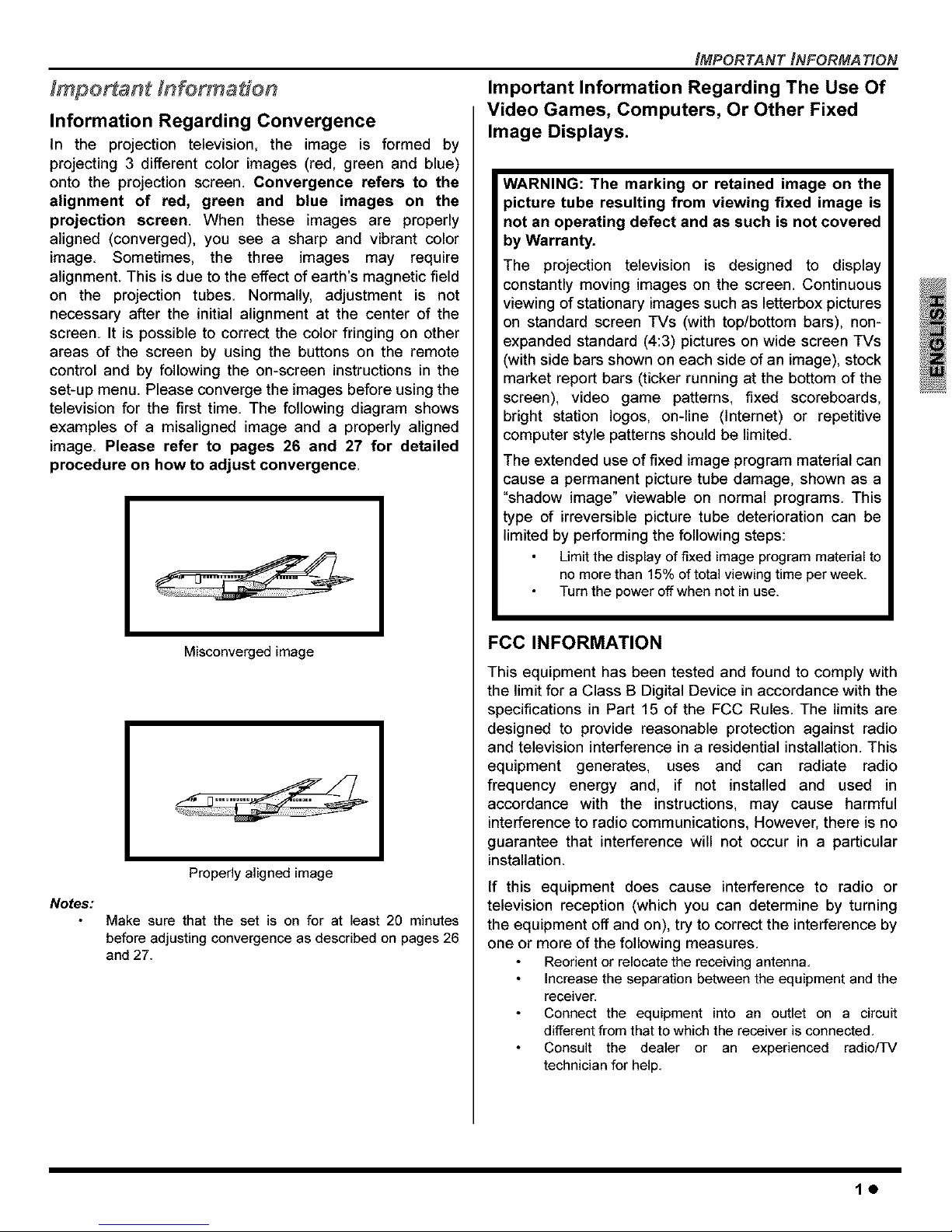
television for the first time. The following diagram shows
examples of a misaligned image and a properly aligned
image. Please refer to pages 26 and 27 for detailed
procedure on how to adjust convergence.
Miscenverged image
Notes:
Properly aligned image
Make sure that the set is on for at least 20 minutes
before adjusting convergence as described on pages 26
and 27.
IMPORTANT INFORMATION
Important Information Regarding The Use Of
Video Games, Computers, Or Other Fixed
Image Displays.
WARNING: The marking or retained image on the
picture tube resulting from viewing fixed image is
not an operating defect and as such is not covered
by Warranty.
The projection television is designed to display
constantly moving images on the screen. Continuous
viewing of stationary images such as letterbox pictures
on standard screen TVs (with top/bottom bars), non-
expanded standard (4:3) pictures on wide screen TVs
(with side bars shown on each side of an image), stock
market report bars (ticker running at the bottom of the
screen), video game patterns, fixed scoreboards,
bright station Iogos, on-line (lnternet) or repetitive
computer style patterns should be limited.
The extended use of fixed image program material can
cause a permanent picture tube damage, shown as a
"shadow image" viewable on normal programs. This
type of irreversible picture tube deterioration can be
limited by performing the following steps:
Limit thedisplay offixed image program material to
no morethan 15%of total viewing time perweek.
Turnthe poweroffwhen not in use.
FCC INFORMATION
This equipment has been tested and found to comply with
the limit for a Class B Digital Device in accordance with the
specifications in Part 15 of the FCC Rules. The limits are
designed to provide reasonable protection against radio
and television interference in a residential installation. This
equipment generates, uses and can radiate radio
frequency energy and, if not installed and used in
accordance with the instructions, may cause harmful
interference to radio communications, However, there is no
guarantee that interference will not occur in a particular
installation.
if this equipment does cause interference to radio or
television reception (which you can determine by turning
the equipment off and on), try to correct the interference by
one or more of the following measures.
Reorient or relocate the receiving antenna.
Increase the separation between the equipment and the
receiver.
Connect the equipment into an outlet on a circuit
different from that to which the receiver is connected.
Consult the dealer or an experienced radio/TV
technician for help.
10
TABLE OF CONTENTS
Important Information ..................................... 1
Information Regarding Convergence ............. 1
Information Regarding The Use Of Video Games
Computers, Or Other Fixed Image Displays ............ 1
Congratulations ............................................... 3
Customer Record ........................................................ 3
Care and Cleaning ...................................................... 3
Specifications .............................................................. 3
Feature Chart .............................................................. 3
Installation ........................................................ 4
Television Location ..................................................... 4
Component Connection Cables .................................. 4
AC Power Supply Cord ............................................... 4
Cable / Antenna Connection ....................................... 4
First Time Setup ......................................................... 4
Front and Rear View of the High Definition
Projection Television .................................... 5
Optional Equipment Connections .................. 6
VCR Connection ......................................................... 6
Digital Cable Module Connection ............................... 6
Digital TV- Set-Top Box (DTV-STB) or DVD Players 6
Front Control Panel ...................................................... 6
HDMI Input Connection ..............................................7
DigitalAudioOut connection......................................8
Program Out Connection............................................8
AmplifierConnection(Analog)....................................8
PIP Operation ...................................................9
PIP Operation ............................................................ 9
Split Operation ............................................................ 9
PIP And Split Operational Buttons ................. 9
TVNideo Button ......................................................... 9
Search Button ............................................................. 9
Move Button ............................................................... 9
PIP MIN and PIP MAX Buttons .................................. 10
Freeze Button ............................................................. 10
Main Picture Freeze Feature ...................................... 10
PIP, Split and Freeze Mode Buttons
Operational Chart .................................................... 10
Special Feature of the High Definition
Projection Television ................................ 11
Special Remote Buttons .............................. 12
Remote Control Operation .......................... 13
Operating Components with Remote Control ............. 14
Programming the Remote .......................................... 16
Programming Without a Code .................................... 16
Component Codes .....................................................16
Basic Menu Navigation.................................19
Menu Operations ...........................................20
Picture ........................................................................ 20
Audio .......................................................................... 20
Channel ...................................................................... 21
Photo Viewer TM Operation .......................................... 22
Timer .......................................................................... 24
Set Up ........................................................................ 25
Lock ............................................................................ 28
Glossary and Acronyms ............................... 31
Troubleshooting Chart ................................. 32
Index ............................................................... 34
20
Your new High Definition Projection Television (PTV)
features state-of-the-art technology for high quality picture
and sound with complete audio/video connections for your
home theater system. Your PTV is designed to give you
many years of enjoyment. It was thoroughly tested and
tuned at the factory for best performance.
Customer Record
The model and serial number of this product are located on
the back of the TV, You should note the model and serial
number in the space provided and retain as a permanent
record of your purchase. This will aid in identification in the
event of theft or loss, Product registration for U.S, customers
is available at: www.prodreg.com/panasonic.
Model
Number
Serial
Number
Care and Cleaning
Projection Screen (Turn PTV Off)
The projection screen is a high precision lens system which
has a protective screen. The protective screen is fully
washable with the following precautions:
Use a mild soap solution orwindowcleaner and a clean
cloth.
DO NOT USEABRASIVE CLEANERS,
Do not use laundry detergent or automatic dishwasher
soap.
Do not use alcohol, ammonia, or petroleum based
products.
Avoid excessive moisture andwipe dry,
Prevent solutionfrom running into the receiver below.
Avoid bumping or scraping the screen,
Note: Do not spray any type of cleaning fluid directly on the
screen,
Cabinet and Remote Control
For cabinets and remote control, use a soft cloth
dampened with water or a milddetergent solution. Avoid
excessive moisture and wipe dry,
Do not use benzene, thinner or other petroleum based
products.
Specifications
Specifications are subject to change without notice or
obligation.
.ow ,sou,ce
PT-47WXD63 (4_1A)
PT-53WXO63 (4;1A)
PT-53TWD63 (4,1A)
P'r_6_D63 (4 !A) .
HDMI Input jack TypeA
!gita! Audio Out jac_ PCM / Do!by* Digital Fiber Optic
Component !nputs _Y ] PB/PR)75 Ohm; PhonQ Ja_kType
ideo Input , 1Vp-p, 75 Ohm, Phono Jac_Type
Audio Input Jacks I 500rnV RMS 47K Ohrn
!dad out jack , 1Vb - ack Type
Audio Output Jacks . 500mV RMS_:TK Ohm
S-Video Input Jacks I -Video (Y-C) Connector
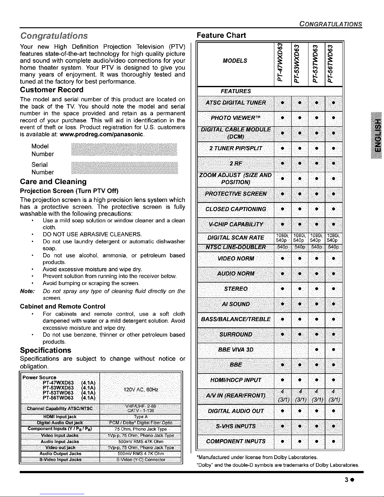
Feature Chart
MODELS
FEATURES
CONGRA TULA TIONS
PHOTO VIEWER_
ZOOM ADJUS _ (SIZE AND
POSITIO N)
DiGiTAL SCANRATE
VIDEONORM
STEREO
BASS/BALANCE/TREBLE
BBE vIvA 3D
HDMI/HDCP iNPuT
DIGITAL AUDIO OUT
COMPONENTINPUTS
*Manufactured under license from Dolby Laboratories.
"Dolby" and the double-D symbols are trademarks of Dolby Laboratories.
30
INS TALLA TION
Television Location
This unit can be used as part of an entertainment center
Consult your dealer for available options
Avoid excessive sunlight or bright lights, including
reflections.
Keep away from excessive heat or moisture. Inadequate
ventilation may cause internal component failure.
Fluorescent lighting may reduce remote control
transmitting range.
Keep away from magnetic equipment, including motors,
fans and external speakers.
Component Connection Cables
Shielded audio and video cables should be used between
components. For best results:
Use 75-ohm coaxial shielded cables.
Use appropriate input and output connectors, that match
your component connectors.
Avoid long cables to minimize interference.
AC Power Supply Cord
CAUTION: TO PREVENT ELECTRIC SHOCK,
MATCH WIDE BLADE OF PLUG TO WIDE SLOT
OF AC OUTLET AND FULLY INSERT. DO NOT Polarizedplug
USE A PLUG WITH A RECEPTACLE OR OTHER
OUTLET UNLESS THE BLADE CAN BE FULLY INSERTED TO
PREVENT BLADE EXPOSURE.
PROTECT POWER CORDS FROM BEING WALKED ON, ROLLED
OVER, CRIMPED, BENT, OR PINCHED, PARTICULARLY AT PLUGS,
CONVENIENCE RECEPTACLES,AND THE POINT WHERE THEY EXIT
FROM THE APPARATUS.
Cable / Antenna Connection
For proper reception of analog or digital cable channels, a
cable service connection is required.
Cable Connection Incoming Cable from
Cable Company
Connect the cable supplied by your local
cable company to ANTENNA (A)
connection on back of television. Select
Cable mode and ANTENNA (A) in SET UP
menu under Program CH (Program
Channels).
Antenna Connection
Note:
75 Ohm ANT A
For proper reception of digital and analog VHF/
UHF channels, an external antenna is required. For
best reception an outdoor antenna is
recommended.
Connect home antenna to IncomingCablefrom
either ANT (A) or ANT (B) HomeAntenna
connection on back of the
television. Select Antenna _"
mode for ANTENNA (A) or
(B) in Input Setup under
Program CH in Setup menu.
Cable Mode is preset at the factor_ Antenna users must
change to ANTENNA Mode for ANTENNA (A) in the Set
Up menu. If you have both Cable and Antenna, the
Cable must be connected to ANT (A).
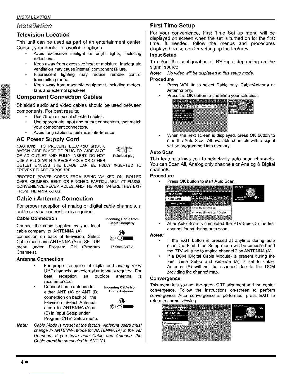
First Time Setup
For your convenience, First Time Set up menu will be
displayed on screen when the set is turned on for the first
time. If needed, follow the menus and procedures
displayed on-screen for setting up the features.
Input Setup
To select the configuration of RF input depending on the
signal source.
Note: No video will be displayed in this setup mode.
Procedure
Press VOL b" to select Cable only, Cable/Antenna or
Antenna only.
Press the OK button to underline your selection.
Cab_ o_ly
When the next screen is displayed, press OK button to
start the Auto Scan. All available channels with a signal
will be programmed into memory.
Auto Scan
This feature allows you to selectively auto scan channels.
You can Scan All, Analog only channels or Analog & Digital
channels.
Procedure
Press OK button to start Auto Scan,
Auto Scan
Notes:
After Auto Scan is completed the PTV tunes to the first
channel found during auto scan.
If the EXIT button is pressed at anytime during auto
scan, the First Time Setup menu will be cancelled and
the PTV will tune to analog channel 2 on ANTENNA (A).
If a DCM (Digital Cable Module) is present during the
First Time Setup and Antenna (A) is set to cable,
Antenna (A) will not be scanned due to the DCM
providing the channel map.
Convergence
This menu lets you set the green CRT alignment and the center
convergence, Follow the instructions on-screen to perform
convergence, After convergence is performed, press EXIT to
return to normal viewing,
40
FRONT AND REAR VIEW OF THE HIGH DEFiNiTION PROJECTION TELEWSfON
Front and Rear View of the High Definition Projection Television
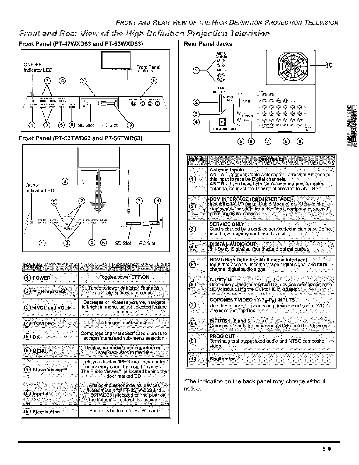
Front Panel (PT-47WXD63 and PT-53WXD63)
O N_(OaFFLED c_ I ;°ntnrto,Fane
(_SD Slot PC Slot_
Front Panel (PT-53TWD63 and PT-56TWD63)
ON/OFF
indicator LED
SD Slot PC Slot
O P0WER. Togg!eSpoweroFFioN
Decrease 0r iacrease va!umel navigate
left/right in menu ad ust seected feature
, in menu
completes channel spe_if!cati0#; press to
accepts menu and sub-menu selection:
Lets yOUdisplay JPEG images recorded
i _ On r:nem0_ Cards by a digita Carneta:
photo v!ewer The Phet0 viewer_ is !oCated behind the
• door marked SD
(_) Ejec_ 6_eon, this button to eect Pc cara:
Rear Panel Jacks
Q--
Q--
Q--
ANT A
Cable I_
/@
ANT B
,,@
[}CM
INTERFACE HDMi _InLQ
L,-,© © © © © ©.......
A B F ©©©©©©'q
5 55
Antenna InPuts
ANT A- Connect Cable Antenna or Terrestrial Antenna to
@ thiS input to receive Digital channe s
ANTB_ !f yOUhave both Cable antenna and Terrestrial
antenna connect the Terrestrial antennato ANT B.
I SERVICE 0NLY
Card SlOtUS_ bYa _rtified ee_i_ technician 0n!y. DO not
! insert any memory card into this slot
HDM! (High DefinitiQn Mu!timedia !nterfaee)
!nput that accepts uncompressed digitaI signa! and multi
, channel digital audio signaL
' CoPONENT VIDE0 (y;PB-PR) INPUTS
use these aCkS for connecting dev cOSSUCh as aDVD
. P!aye[ 0r Set TOp BOX.
*The indication on the back panel may change without
notice.
50
OPTIONAL eQUIPMENT CONNECTIONS
Optional Equipment Connections
Note: The remote control must be programmed with supplied
codes to operate the optional equipment.
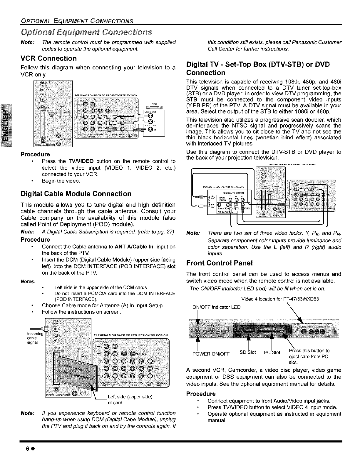
VCR Connection
Follow this diagram when connecting your television to a
VCR only.
Procedure
Press the "rVNIDEO button on the remote control to
select the video input (VIDEO 1, VIDEO 2, etc.)
connected to your VCR.
Begin the video.
Digital Cable Module Connection
This module allows you to tune digital and high definition
cable channels through the cable antenna. Consult your
Cable company on the availability of this module (also
called Point of Deployment (POD) module).
Note: A Digital Cable Subscription is required. (refer to pg. 27)
Procedure
Connect the Cable antenna to ANT A/Cable In input on
the back ofthe PTV.
Insert the DCM (Digital Cable Module) (upper side facing
left) into the DCM INTERFACE (POD INTERFACE) slot
on the back of the PTV.
Notes:
Left side is the upper side of the DCM cards.
Do not insert a PCMCIA card into the DCM INTERFACE
(POD INTERFACE).
Choose Cable mode for Antenna (A) in Input Setup.
Follow the instructions on screen.
cable
signal
Note:
Left side (upper side)
of card
If you expedence keyboard or remote control function
hang-up when using DCM (Digital Cabe Module), unplug
the PTV and plug it back on and try the controls again. If
this condition still exists, please call Panasonic Customer
Call Center for further instructions.
Digital TV - Set-Top Box (DTV-STB) or DVD
Connection
This television is capable of receiving 1080i, 480p, and 480i
DTV signals when connected to a DTV tuner set-top-box
(STB) or a DVD player. In order to view DTV programming, the
STB must be connected to the component video inputs
(Y,PB,PR) of the PTV. A DTV signal must be available in your
area. Select the output of the STB to either 1080i or 480p.
This television also utilizes a progressive scan doubler, which
de-interlaces the NTSC signal and progressively scans the
image. This allows you to sit close to the TV and not see the
thin black horizontal lines (venetian blind effect) associated
with interlaced TV pictures.
Use this diagram to connect the DTV-STB or DVD player to
the back of your projection television.
_r_,s _ SACK_ _ROaECvIO.__,_W=O.
V_DE°
IDEC
........ i
Note: There are two set of three video lacks, Y, PB, and PR.
Separate component color inputs provide luminance and
color separation. Use the L (left) and R (right) audio
inputs.
Front Control Panel
The front control panel can be used to access menus and
switch video mode when the remote control is not available.
TheON/OFF indicator LED (red) will be lit when set is on.
Video 4 location for PT-47/53WXD63
ON/OFF Indicator LED
POWER ON/OFF SD Slot PC
eject card from PC
slot.
A second VCR, Camcorder, a video disc player, video game
equipment or DSS equipment can also be connected to the
video inputs. See the optional equipment manual for details.
Procedure
Connect equipment to front AudioNideo inputjacks.
Press TVNIDEO button to select VIDEO 4 input mode.
Operate optional equipment as instructed in equipment
manual.
60
HDMI (High Definition Multimedia Interface)
input connection
About HDMI
HDMI is the first all digital consumer electronics AN
interface that supports several uncompressed standard,
enhanced and high definition video format as well as
existing multi-channel audio format. One jack supports both
video and audio information. The HDMI/HDCP 1 input can
be connected to an EiA/CEA 8612 compliant consumer
electronic device, such as a set top box or DVD player
equipped with a HDMI or DVI output connection. By
inputting a High-bandwidth Digital Content Protection
(HDCP) high definition picture source to the HDMI terminal
of this PTV, high definition pictures can be displayed on the
screen in their digital form. The HDMI input terminal is not
intended to be used with personal computers. This PTV is
compatible with 1080i, 480p and 480i formats. Select the
output of the connecting to device to match that of the PTV.
Notes:
1. HDMI/HDCP = High Definition Multimedia Interface /
High-Bandwidth Digital Copy Protection.
2. EiA]CEA-861 Profiles compliance covers profiles for
transmission of uncompressed digital video including
high bandwidth digital content protection.
Compatible formats
This PTV is compatible with following formats. Please set
the connecting device to following format.
Video signal
1080i
540p (480p)
540p (480i)
Audio signal
1920 x 1080i 59.94/60
720 x 480p 59.94/60
640 x480p 59.94/60
720 x 480i 59.94/60
When digital audio is included in the HDMI connection,
the compatible sampling frequencies are 48 KHz /
44.1Khz / 32 Khz.
OPTIONAL eQUiPMENT CONNECTIONS
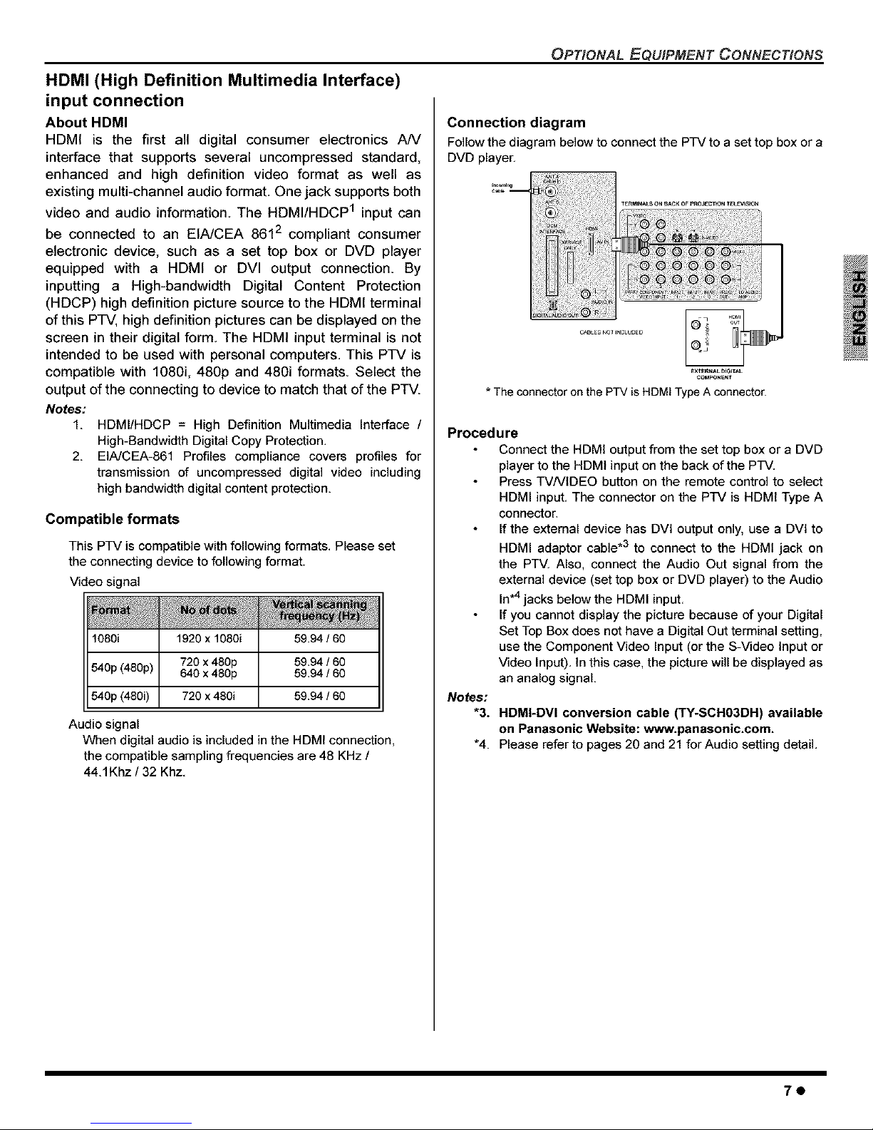
Connection diagram
Follow the diagram below to connect the PTV to a set top box or a
DVD player.
:11
CABLES NO1 _NCLL_ED
EXI_NAL [) JGITAL
COMPON_t
* The connector on the PTV is HDMI Type A connector.
Procedure
Connect the HDMI output from the set top box or a DVD
player to the HDMI input on the back of the PTV.
Press TVNIDEO button on the remote control to select
HDMI input. The connector on the PTV is HDMI Type A
connector.
If the external device has DVI output only, use a DVI to
HDMI adaptor cable .3 to connect to the HDMI jack on
the PTV. Also, connect the Audio Out signal from the
external device (set top box or DVD player) to the Audio
In.4 jacks below the HDMI input.
If you cannot display the picture because of your Digital
Set Top Box does not have a Digital Out terminal setting,
use the Component Video Input (or the S-Video input or
Video Input). In this case, the picture will be displayed as
an analog signal.
Notes:
"3.
"4.
HDMI-DVI conversion cable (TY-SCH03DH) available
on Panasonic Website: www.panasonic.com.
Please refer to pages 20 and 21 for Audio setting detail,
70
OP_ONAL eQUIPMENT CONNEC_ONS
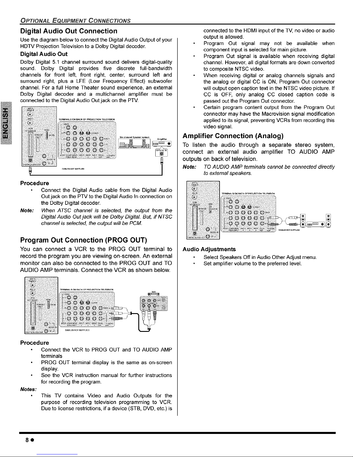
Digital Audio Out Connection
Use the diagram below to connect the Digital Audio Output of your
HDTV Projection Television to a Dolby Digital decoder.
Digital Audio Out
Dolby Digital 5,1 channel surround sound delivers digital-quality
sound, Dolby Digital provides five discrete full-bandwidth
channels for front left, front right, center, surround left and
surround right, plus a LFE (Low Frequency Effect) subwoofer
channel For a full Home Theater sound experience, an external
Dolby Digital decoder and a multichannel amplifier must be
connected to the Digital Audio Out jack on the PTV,
Procedure
Connect the Digital Audio cable from the Digital Audio
Out jack on the PTV to the Digital Audio In connection on
the Dolby Digital decoder.
Note: When ATSC channel is selected, the output from the
Digital Audio Out jack will be Dolby Digital. But, if NTSC
channel is selected, the output will be PCM.
Program Out Connection (PROG OUT)
You can connect a VCR to the PROG OUT terminal to
record the program you are viewing on-screen. An external
monitor can also be connected to the PROG OUT and TO
AUDIO AMP terminals Connect the VCR as shown below
Procedure
Connect the VCR to PROG OUT and TO AUDIO AMP
terminals
PROG OUT terminal display is the same as on-screen
display.
See the VCR instruction manual for further instructions
for recording the program.
Notes:
This TV contains Video and Audio Outputs for the
purpose of recording television programming to VCR.
Due to license restrictions, ifa device (STB, DVD, etc.) is
connected to the HDMI input of the TV, no video or audio
output is allowed.
Program Out signal may not be available when
component input is selected for main picture.
Program Out signal is available when receiving digital
channel. However, all digital formats are down converted
to composite NTSC video.
When receiving digital or analog channels signals and
the analog or digital CC is ON, Program Out connector
will output open caption text in the NTSC video picture. If
CC is OFF, only analog CC closed capfion code is
passed out the Program Out connector.
Certain program content output from the Program Out
connector may have the Macrovision signal modification
applied to its signal, preventing VCRs from recording this
video signal.
Amplifier Connection (Analog)
To listen the audio through a separate stereo system,
connect an external audio amplifier TO AUDIO AMP
outputs on back of television.
Note: TO AUDIO AMP tetTninals cannot be connected directly
to external speakers.
Audio Adjustments
Select Speakers Off in Audio Other Adjust menu.
Set amplifier volume to the preferred level.
80
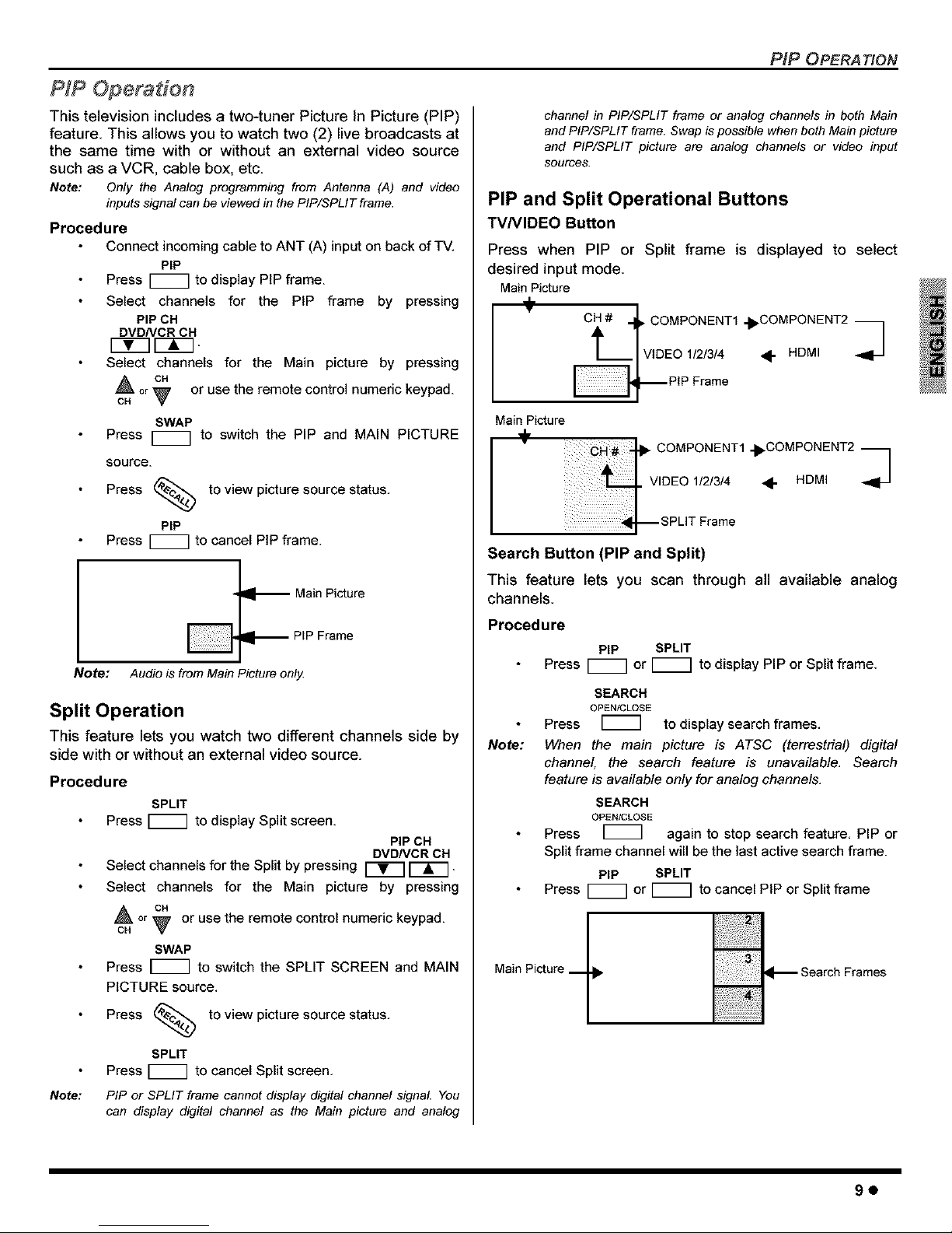
PIP Operation
This television includes a two-tuner Picture In Picture (PIP)
feature. This allows you to watch two (2) live broadcasts at
the same time with or without an external video source
such as a VCR, cable box, etc.
Note: Only the Analog programming from Antenna (A) and video
inputssignal can be viewed in the PIP/SPLIT frame.
Procedure
Connect incoming cable to ANT (A) input on back of TV.
PIP
Press _ to display PIP frame.
Select channels for the PIP frame by pressing
PIP OH
DVDNCR OH
Select channels for the Main picture by pressing
or or use the remote control numeric keypad.
SWAP
Press _ to switch the PIP and MAIN PICTURE
source.
Press _--_ to view picture source status.
PIP
Press _ to cancel PIP frame.
Main Picture
PiP Frame
Note: Audio is from Main Picture only
Split Operation
This feature lets you watch two different channels side by
side with or without an external video source.
Procedure
SPLIT
Press i'm] to display Split screen.
Note:
PIP CH
DVDNCR CH
Select channels for the Split by pressing _ I---_'--] -
Select channels for the Main picture by pressing
or _ or use the remote control numeric keypad.
CH
SWAP
Press _ to switch the SPLIT SCREEN and MAIN
PICTURE source.
Press _.) to view picture source status.
SPLIT
Press _ to cancel Split screen.
PIP or SPLIT frame cannot display digital channel signal You
can display digital channel as the Main picture and analog
PiP OPERA TION
channel in PIP/SPLIT frame or analog channels in both Main
and PIP/SPLIT frame. Swap is possible when both Main picture
and PIP/SPLIT picture are analog channels or video input
sources.
PIP and Split Operational Buttons
TVNIDEO Button
Press when PIP or Split frame is displayed to select
desired input mode.
Main Picture
÷
CH # ,,_ COMPONENT1 _ I
i___._1_] VIDEO "I_COMPONENT2
1121314
<-
HDMI
_PIP Frame
Main Picture
COMPONENTI-I_COMPONENT2 _
VIDEOI/_3/4 <1" HDMI
Search Button (PIP and Split)
This feature lets you scan through all available analog
channels.
Procedure
PIP SPLIT
Press _ or _ to display PIP or Split frame,
Note:
SEARCH
OPEN/CLOSE
Press to display search frames,
When the main picture is ATSC (terrestrial) digital
channel the search feature is unavailable, Search
feature is available onJ/ for analog channels,
SEARCH
OPEN/CLOSE
Press again to stop search feature, PIP or
Split frame channel will be the last active search frame.
PIP SPLIT
Press _ or _ to cancel PIP or Split frame
Main Picture ___
90
PIP OPERA TION
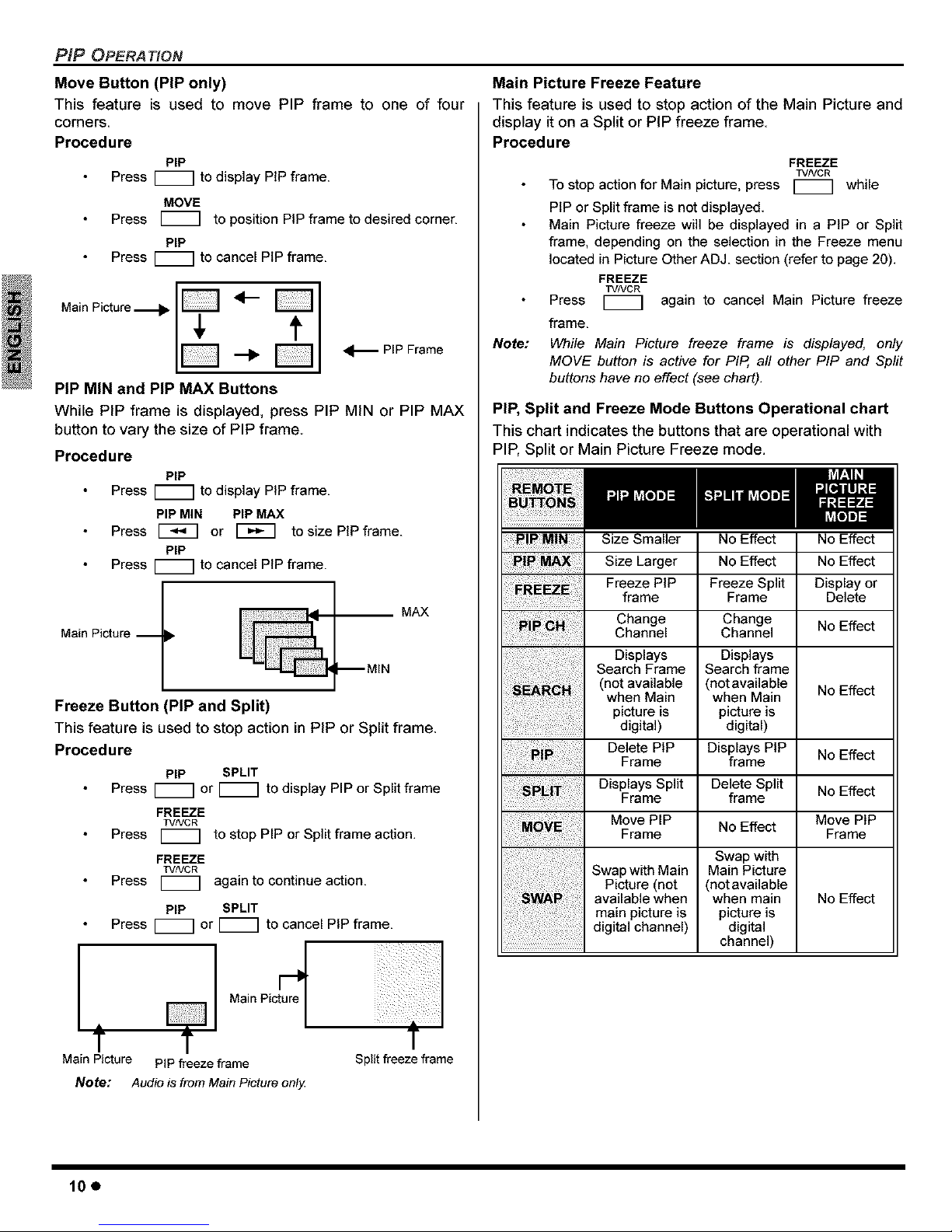
Move Button (PIP only)
This feature is used to move PIP frame to one of four
corners.
Procedure
PIP
Press _ to display PiP frame.
MOVE
Press _ to position PiP frame to desired corner.
PIP
Press r_] to cancel PIP frame.
_._ PIP Frame
PIP MIN and PIP MAX Buttons
While PIP frame is displayed, press PIP MIN or PIP MAX
button to vary the size of PIP frame
Procedure
PIP
Press r_] to display PiP frame.
PIP MIN PIP MAX
Press [_ or _ to size PIP frame.
PIP
Press _ to cancel PIP frame.
MAX
Main Picture -- •
Freeze Button i PIP and Split)
This feature is used to stop action in PIP or Split frame.
Procedure
PIP SPLIT
Press _ or r_] to display PIP or Split frame
FREEZE
TVNCR
Press I_ to stop PIP or Split frame action.
FREEZE
TVNCR
Press again to continue action.
PiP SPLIT
Press I_ or I_ to cancel PIP frame.
Main Picture PIP freeze frame
Note: Audio is from Main Picture only
Split freeze frame
Main Picture Freeze Feature
This feature is used to stop action of the Main Picture and
display it on a Split or PiP freeze frame
Procedure
Note:
FREEZE
TVNCR
To stop action for Main picture, press _ while
PIP or Split frame is not displayed.
Main Picture freeze will be displayed in a PiP or Split
frame, depending on the selection in the Freeze menu
located in Picture Other ADJ. section (refer to page 20).
FREEZE
TVNCR
Press again to cancel Main Picture freeze
frame.
While Main Picture freeze frame is displayed, only
MOVE button is active for PIP, all other PIP and Sprit
buttons have no effect (see chart).
PIP, Split and Freeze Mode Buttons Operational chart
This chart indicates the buttons that are operational with
PIP, Split or Main Picture Freeze mode.
PIP M!N Size Smaller No Effect No Effect
Size Larger No Effect No Effect
Freeze PIP Freeze Split Display or
frame Frame Delete
Change Change
Channel Channel No Effect
SearchDisplaysFrame SearchDisplaysframe
(not available (not available
No Effect
when Main when Main
picture is picture is
digital) digital)
Delete PIP Displays PIP No Effect
Frame frame
Displays Split Delete Split No Effect
Frame frame
Move PIP No Effect Move PIP
Frame Frame
Swap with Main Main PictureSwap with
Picture (not (not available
available when when main No Effect
main picture is picture is
digital channel) digital
channel)
10e
SPECIAL FEATURES OF THE HIGH DEFINITION PROJECTION TELEVISION
Special Features of the HLgh Definition Projection Television
Channel and Program Tuning
Channel and Program tuning in digital television is different from
current conventional television. In DTV, up to six (6) multiple
programs can exist within a single 6MHZ channel. These
channels behave as sub-channels within a single channel. When
tuning to a digital channel, the HDTV Projection Television will
also tune to a program. The HDTV Projection Television will
indicate the channel and program using the on-screen Channel
Banner display.
Note: In order to select channels properly, Auto Scan must be
perormed ( refer to page 25).
Tuning digital and analog channels
You can tune the digital and analog channels in the following
ways:
O Direct tuning (0 - 9 keys) - using the numeric keys on the
Remote control to directly input the Channel number. If
the e button to enter the program number ofnecessary,
use
the digital channel.
O Channel Up/Down Tuning (CH • or CH • buttons) - Tunes
to the next or previous available channel or program. The
Channel Up/Down tuning depends upon the surfing mode
(see pg. 21) you have set in the Channel menu.
O Rapid Tuning (R-TUNE) - Switches between the last two
channels or programs.
Direct Tuning Method
Follow the procedure below to directly enter the channel number
using the Remote Control numeric keys.
Procedure
Press the numeric keys on the Remote Control to enter
the Channel number. Press OK button.
If tuning a digital channel and your channel contains
more than one program, press the E) button and enter
the program # (1, 2, 3 etc.) using the numeric keys.
Press OK button. The following is an example of tuning
to channel 15-1.
Direct Tuning Example
1 Press 1 1
2 Press 5 15
3 Press _ 15-
4 Press 1 15-1
5 Press OK 15-1
The HDTV Projection Television will tune to channel 15-1.
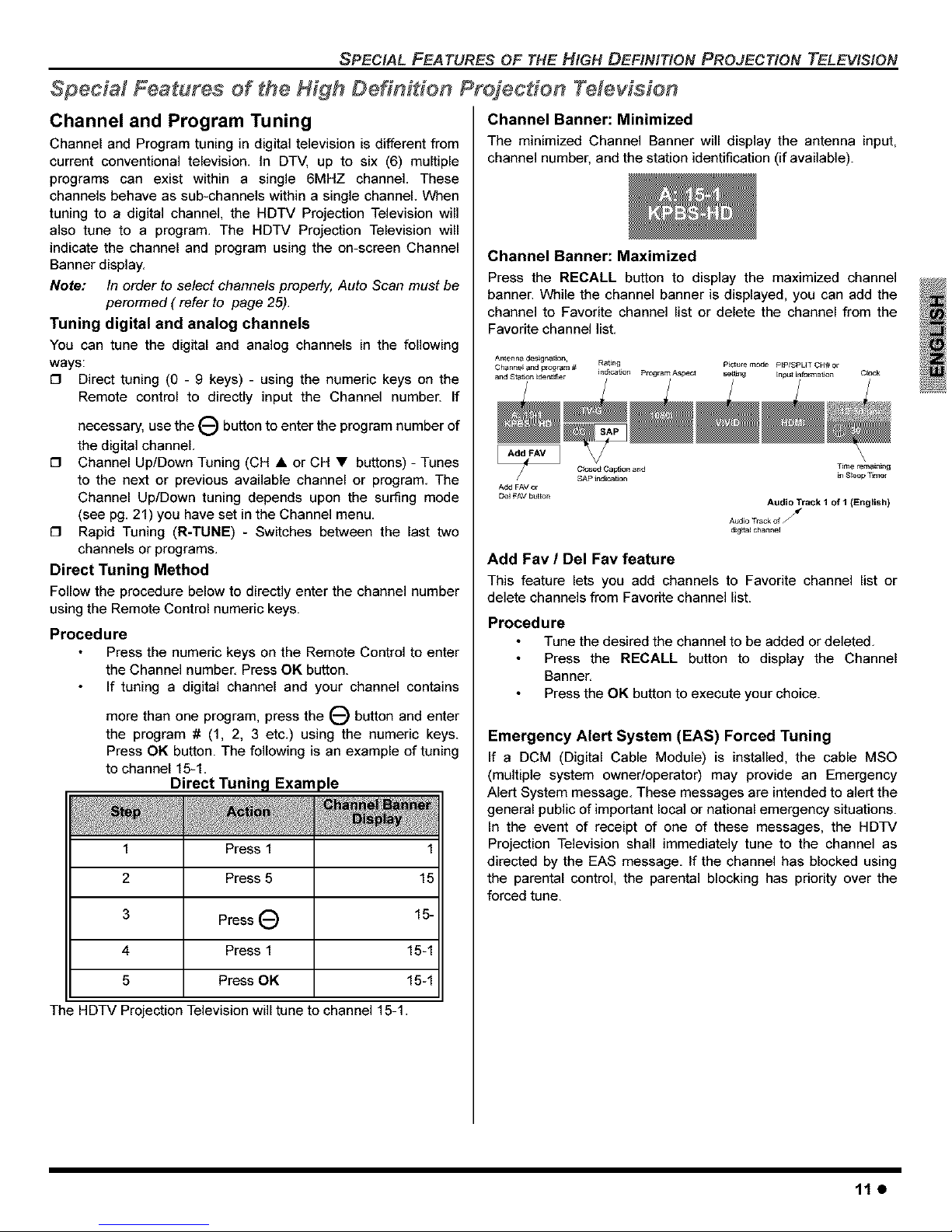
Channel Banner: Minimized
The minimized Channel Banner will display the antenna input,
channel number, and the station identification (if available).
Channel Banner: Maximized
Press the RECALL button to display the maximized channel
banner. While the channel banner is displayed, you can add the
channel to Favorite channel list or delete the channel from the
Favorite channel list.
Audio Track I of I (English)
Audio TrackofJ
dig_l cha_nel
Add Fav / Del Fav feature
This feature lets you add channels to Favorite channel list or
delete channels from Favorite channel list.
Procedure
Tune the desired the channel to be added or deleted.
Press the RECALL button to display the Channel
Banner.
Press the OK button to execute your choice.
Emergency Alert System (EAS) Forced Tuning
If a DCM (Digital Cable Module) is installed, the cable MSO
(multiple system owner/operator) may provide an Emergency
Alert System message. These messages are intended to alert the
general public of important local or national emergency situations.
In the event of receipt of one of these messages, the HDTV
Projection Television shall immediately tune to the channel as
directed by the EAS message. If the channel has blocked using
the parental control, the parental blocking has priority over the
forced tune.
11e
 Loading...