

Panasonic PT-52LCX65-K, PT-44LCX65-K, PT-61LCX65-K, PT-52LCX15K Operating Instructions Manual
LSQT0961 C
Multimedia Projection HDTV
Operating Instructions
PT-44LCX65-K/
PT-52LCX65-K/
PT-61LCX65-K
Models No.
Before connecting, operating or adjusting this product, please read the instructions completely.
Please keep this manual for future reference.
This operating instruction book is designed for use with models PT-44LCX65-K, PT-52LCX65-K and
PT-61LCX65-K. Illustrations in this manual show the PT-52LCX65-K.
* The presence of the DTV certification mark indicates that this product will successfully
receive digital television transmissions that conform to any and all of the video formats
described in the ATSC Digital Television Standard.
ATSC CERTIFIED *
DIGITAL TELEVISION
2
1) Read these instructions before using, connecting or adjusting this product.
2) Keep these instructions for future reference.
3) Heed all warnings on the product and in this Operating Instructions manual.
4) Follow all instructions carefully.
5) Do not use this apparatus near water. For example, near a bathtub, washbowl, kitchen sink, or laundry tub, in
a wet basement or near a swimming pool, and the like. Do not place objects filled with water, such as a vase or
the like, on top of this unit.
6) Clean only with a dry cloth. Do not use liquid cleaners or aerosol cleaners.
7) Do not block any ventilation openings. Install in accordance with the manufacturer’s instructions.
Openings in the cabinet are provided for ventilation to ensure reliable operation and to protect it from
overheating. Never block openings by placing the product on a bed, sofa or similar surfaces.
8) Do not install near any heat source such as radiators, heat registers, stoves, or other apparatus
(including amplifiers) that produces heat. Do not install in a built-in installation such as a bookcase or rack,
unless proper ventilation is provided or the manufacturer’s instructions have been adhered to.
9) Do not defeat the safety purpose of the polarized or grounding-type plug. A polarized plug has two
blades with one wider than the other. A grounding type plug has two blades and a third grounding
prong. The wide blade or the third prong are provided for your safety. If the provided plug does not fit
into your outlet, consult an electrician for replacement of the obsolete outlet.
10) Protect the power cord from being walked on or pinched particularly at plugs, convenience receptacles,
and the point where they exit from the apparatus.
11) Only use attachments/accessories specified by the manufacturer.
12) Use only with the cart, stand, tripod, bracket, or table specified by the manufacturer, or
sold with the apparatus. When a cart is used, use caution when moving the cart/apparatus
combination to avoid injury from tip-over.
13) Unplug this apparatus during lightning storms or when unused for long periods of time.
14) Refer all servicing to qualified service personnel. Servicing is required when the apparatus has been
damaged in any way, such as power-supply cord or plug is damaged, liquid has been spilled or objects
have fallen into the apparatus, the apparatus has been exposed to rain or moisture, does not operate
normally, or has been dropped.
15) Because the temperature of the lamp unit is elevated immediately after its use, a direct touch to it may cause
burns. Replace the lamp unit only after it has cooled.
Note to CATV System Installer:
This reminder is provided to call the CATV system installer’s attention to Article 820-40 of the NEC that provides
guidelines for proper grounding and, in particular, specifies that the cable ground shall be connected to the grounding
system of the building, as close to the point of cable entry as practical.
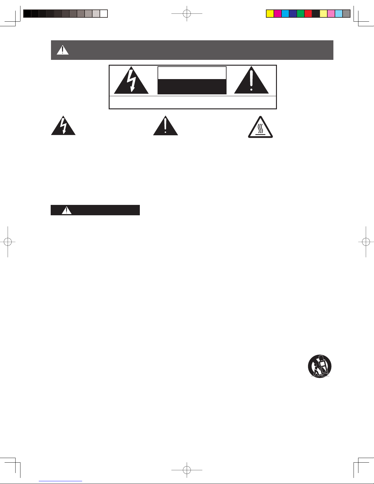
WARNING: To reduce the risk of electric shock, do not remove cover or back. No
user-serviceable parts inside. Refer servicing to qualified service personnel.
CAUTION
RISK OF ELECTRIC SHOCK
DO NOT OPEN
This symbol warns the
user that uninsulated
voltage within the unit may
have sufficient magnitude
to cause electric shock.
Therefore, it is dangerous
to make any kind of
contact with any inside part
of this unit.
This symbol alerts the
user that important
literature concerning
the operation and
maintenance of this unit
has been included.
Therefore, it should be
read carefully in order to
avoid any problems.
The pictorial
representation of a hot
surface within a triangle
is intended to tell the
user that parts inside the
product are a risk of burns
to persons.
WARNING
To reduce the risk of electric shock, fire, injury to persons or damage to this product:
IMPORTANT SAFETY INSTRUCTIONS
3
Getting Start ed
The Lamp is a consumable item and has a limited life.
The lamp should be changed as soon as possible once the lamp warning message appears. (See page 66.)
If the lamp is damaged, please contact your nearest dealer.
Due to the characteristics and use conditions of in di vid u al lamps, the lamp may cease to light before the
stated lamp life.
Influences of fre quent light ing, continuous light use for over 24 hours, the number of times lit, the length of
time between lightings, etc. may shorten lamp life.
(Because of this, we recommend having a replacement lamp on hand.)
Trademarks
• VGA and XGA are trademarks of International Business Machines Corporation.
• Macintosh is a registered trademark of Apple Computer, USA.
• SVGA is trademark of the Video Electronics Standard Association.
Even if no special notation has been made of company or product trademarks, these trademarks have been fully respected.
• Equipped with -TV Noise Reduction for true MTS reproduction. -TV Noise Reduction is required for good stereo
separation and audio fidelity. is a registered trademark, and is licensed by Technology Licensing.
• CableCARDTM is a trademark of Cable Television Laboratories, Inc.
WARNING
AS WITH ANY SMALL OBJECT, SD CARDS CAN BE SWALLOWED BY YOUNG CHILDREN. DO NOT ALLOW
CHILDREN TO HANDLE THE SD CARD.
CAUTION
HDMI, the HDMI logo and
High Definition Multimedia
Interface are trademarks or
registered trademarks of HDMI
Licensing LLC.
SD Logo is a trademark.
(1) This Projection Display is intended to be used with the following TV stand: model TY-44LC65C-K for the
PT-44LCX65-K, TY-52LC65C-K for the PT-52LCX65-K, and TY-61LC65C-K for the PT-61LCX65-K. Use with other
stands may result in the Projection Display becoming unstable, possibly causing injury.
(2) This Projection Display should not be exposed to direct sunlight, extreme temperatures or moisture, as this can
result in serious irreparable damage.
Manufactured under license from BBE Sound, Inc.
Licensed by BBE Sound, Inc. under USP5510752
and 5736897. BBE and BBE symbol are registered
trademarks of BBE Sound, Inc.
U.S. Patent Nos. 4,631,603; 4,577,216; 4,819,098; 4,907,093; 6,381,747; and 6,516,132.
This product incorporates copyright protection technology that is protected by U.S. patents and other intellectual
property rights. Use of this copyright protection technology must be authorized by Macrovision, and is intended
for home and other limited viewing uses only unless otherwise authorized by Macrovision. Reverse engineering
or disassembly is prohibited.
Manufactured under license from Dolby
Laboratories. Dolby and the double-D symbol
are trademarks of Dolby Laboratories.
IMPORTANT SAFETY INSTRUCTIONS (CONTINUED)
License description: To view the license information for software used in this product, press the Menu button and
select “Setup”→“About”→“License”. (See page 57).
Note:
• Do not allow a still picture to be displayed for an extended period, as this can cause a permanent afterimage to remain on this
unit. Examples of still pictures include logos, video games, computer images, teletext and images displayed in 4:3 mode.
WARNING
TO REDUCE THE RISK OF FIRE OR ELECTRIC SHOCK, DO NOT EXPOSE THIS EQUIPMENT TO RAIN OR
MOISTURE. DO NOT PLACE OBJECTS FILLED WITH WATER, SUCH AS A VASE OR THE LIKE, ON TOP OF
THIS APPARATUS.
4
Welcome to the Panasonic family of customers. We hope that you will have many years of enjoyment from your new
Projection Display.
To obtain maximum benefit from your set, please read these Instructions before making any adjustments, and retain
them for future reference.
Retain your purchase receipt also, and record the serial number of your set in the space provided on the rear cover
of these instructions.
The ClassⅡ insulation symbol (square within a square) indicates that this product has been evaluated
and tested to comply with ClassⅡ insulation requirements.
Dear Panasonic Customer
5
Getting Start ed
To
Start !
Use
Now !
Enjoy
More !
Other
Information !
IMPORTANT SAFETY INSTRUCTIONS ...............................................2
Before Using ..............................................................................................6
Location of Controls .................................................................................9
Installation ................................................................................................12
Power ON / OFF .......................................................................................24
Basic Menu Navigation ...........................................................................26
Tuning channels ......................................................................................28
Projection Display operation ..................................................................32
ASPECT Controls ....................................................................................36
Split screen ..............................................................................................37
Picture Adjustments................................................................................39
Audio Adjustments ..................................................................................42
Sleep Timer Feature ................................................................................44
Lock Feature ............................................................................................45
Photo Viewer ............................................................................................49
Setup Features ........................................................................................54
Remote Control Quick Reference Guide (Operating peripheral equipment)
......58
Warning Indicators ..................................................................................65
Replacing the lamp unit ..........................................................................66
Troubleshooting ......................................................................................68
Specifications ..........................................................................................69
Cleaning ...................................................................................................70
Limited Warranty / Servicentre List .......................................................71
Other Information ....................................................................................72
Index .........................................................................................................79
Table of Contents
Getting Start ed Basic Operation InformationAdvanced Op er a tion
6
Accessories
1. Remote Control (EUR7627Z70)
2. Batteries 2 “AA”
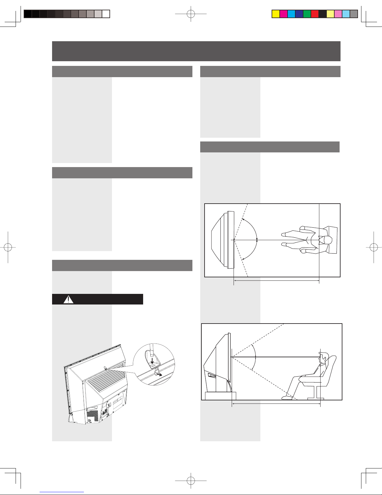
Viewing position
<Side view>
<Top view>
To optimize your viewing comfort, please follow the
viewing guidelines shown in the diagrams below.
If viewing for an extended period of time, sit as far back
from the screen as possible.
70º
At least
1.6 m (PT-44LCX65-K) /
1.8 m (PT-52LCX65-K) /
2.2 m (PT-61LCX65-K).
70º
30º
30º
Receiver Location
Locate for comfortable viewing. Avoid placing where
sunlight or other bright light (including reflections) will fall
on the screen.
Use of some types of fluorescent lighting can reduce
Remote Control transmitter range.
Adequate ventilation is essential to prevent internal
component failure. Keep away from areas of excessive
heat or moisture.
Optional External Equipment
The Video / Audio connection between components can
be made with shielded video and audio cables. For best
performance, video cables should utilize 75 Ω coaxial
shielded cables. Cables are available from your dealer
or electronic supply house.
Before you purchase any cables, be sure you know
what type of output and input connectors your various
com po nents require. Also determine the length of cable
you’ll need.
Safety Precaution
Please take safety precautions to prevent the unit from
falling over.
WARNING
The unit may tip or fall if not situated on a stable
surface, if pushed or during an earthquake. Use
a strong rope or chain (not included) to fasten the
Projection Display firmly to a strong wall support.
Before Using
At least
1.6 m (PT-44LCX65-K) /
1.8 m (PT-52LCX65-K) /
2.2 m (PT-61LCX65-K).
7
Getting Start ed
Emergency Alert System ( EAS)
Forced Tuning
If a CableCARDTM is installed, the cable MSO
(multiple system owner/operator) may provide an
Emergency Alert System message. These messages
are intended to alert the general public of important
local or national emergency situations. In the event
of receipt of one of these messages, the Projection
Display shall immediately tune to the channel as
directed by the EAS message. If the channel has
been blocked using the parental control, the parental
blocking has priority over the forced tune.
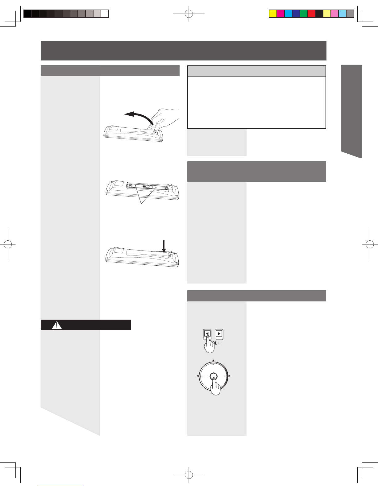
Requires two AA batteries (supplied).
2. Install the batteries as shown in the battery
compartment.
(Polarity + or - must match the markings in the
compartment).
Two AA size
Remote Control Battery Installation
CAUTION
1. While pressing in on the catch, open cover in
direction of arrow.
3. Press cover in direction of arrow until it snaps
shut.
Incorrect battery installation can cause the batteries to
leak, leading to personal injury and/or damage to the
remote control.
Observe the following precautions:
1. Batteries should always be replaced as a pair.
Always use new batteries when replacing the old
set.
2. Do not combine a used battery with a new one.
3. Do not mix battery types (example: “Zinc Carbon”
with “Alkaline”).
4. Do not attempt to charge, short-circuit, disassemble,
heat or burn used batteries.
5. Battery replacement is necessary when the remote
control acts sporadically or stops operating the
Projection Display set.
Helpful Hints:
(1) For frequent remote control users, replace old
batteries with Alkaline batteries for longer battery
life.
(2) Whenever you remove the batteries, you may
need to reset the remote control infrared
codes. We rec om mend that you record the code
on pages 58-59, prior to setting up the remote.
Reset All Memory Functions
Use when moving unit to a new location, or First Time
Setup needs to be redone.
Press the VOL- button on the unit
and OK button on the Remote
control at the same time for more
than 3 seconds. When reset is done,
power shuts off automatically.
CH
CH
VOL VOL
OK

8
CC (Closed Captioning)
EAS (Emergency Alert System)
OSD (On-Screen Display)
MSO (Multiple system owner/operator)
Dolby Digital
This is a method of coding digital signals developed by
Dolby Laboratories. Apart from stereo (2-channel) audio,
these signals can also be multichannel audio. A large
amount of audio information can be recorded on one
disc using this method.
PCM (pulse code modulation)
These are uncompressed digital signals, similar to those
found on CDs.
DTV (Digital Television)
Name of the process whereby television picture and
sound signals are changed to digital code for receiving
and transmitting.
HDTV (High Definition Television)
Television with improved picture quality by increasing
vertical and horizontal resolution.
Glossary and Acronyms
ATSC (Advanced Television Systems Committee)
Standardization body that developed the Digital
Television Terrestrial formats.
HDMI (High Definition Multimedia Interface)
Interface that supports every uncompressed digital
format as well as all existing multi-channel audio format
on a single cable.
JPEG (Joint Photographic Experts Group)
A system used for compressing/decoding color still
pictures.
MPAA (Motion Picture Association of America)
Guild governing rating assignments to movies.
NTSC (National Television Systems Committee)
Standardization body that developed the Analog
Television Terrestrial formats.
Password
A four (4) digit code a user must provide in order to
perform a function.
CableCARD
TM
A module that is required to receive premium digital
services through the cable input.
Before Using (continued)
9
Getting Start ed
Note:
• This section describes TV mode only. For other modes, see
pages 58-64.
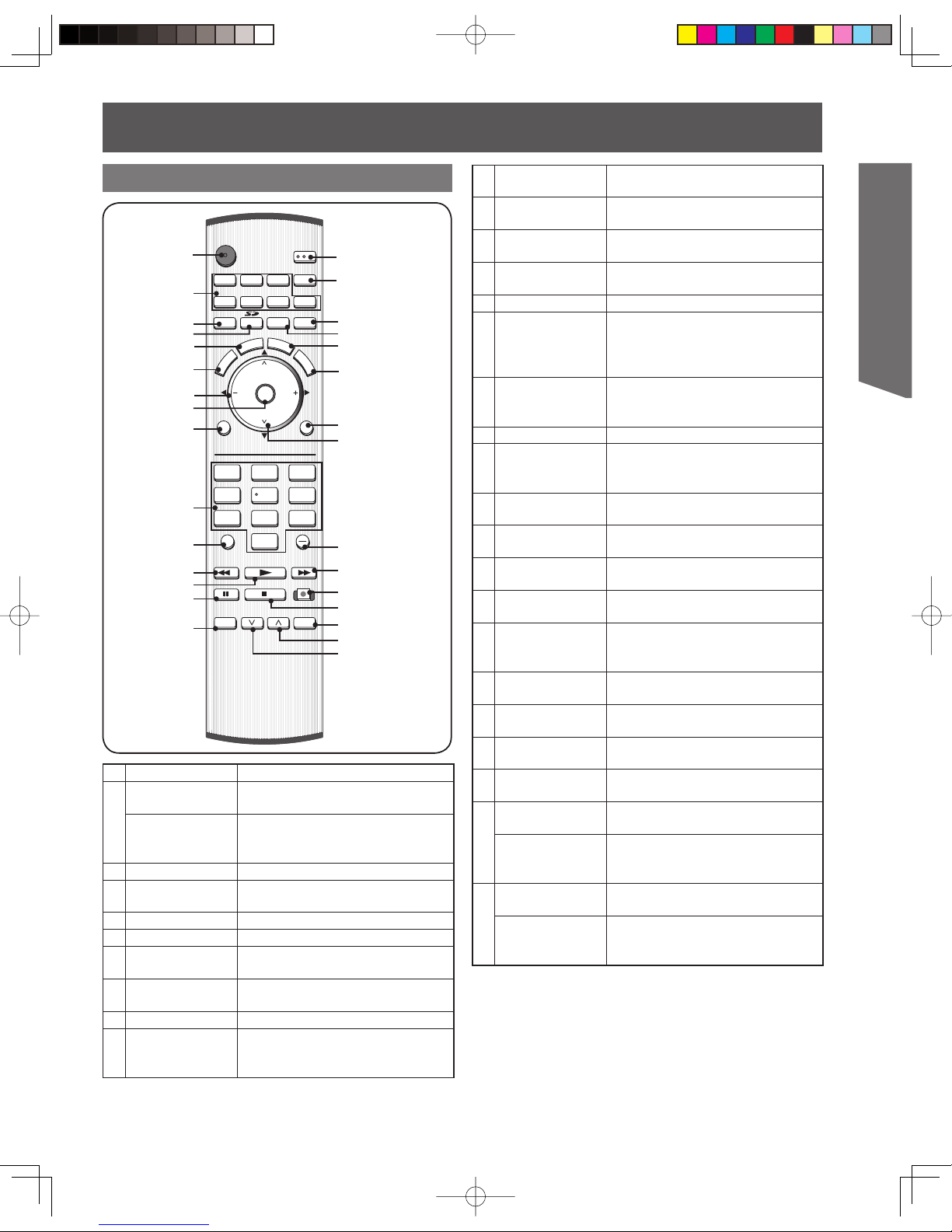
Illuminated Remote Control
POWER
SAP
LIGHT
MENU
123
4
5
6
7809
RETURN
CH
CH
VOL VOL
R-TUNE
REW
TV/VCR
SPLIT SWAP
DVD/VCR CH
OPEN/CLOSE
PLAY
PAUS E STO P REC
FF
PROG
TV/VIDEO
SLEEP EXIT
TV VCR DVD
DTV RCVR
DBS/CBL
AUX
OK
M
U
T
E
A
S
P
E
C
T
F
A
V
O
R
I
T
E
R
E
C
A
L
L
1
2
3
4
5
6
7
8
9
10
11
12
13
14
15
16
17
18
20
21
22
24
25
26
27
28
29
23
19
30
Location of Controls
1
POWER Press to turn ON and OFF.
2
TV
Sets the remote to communicate
with television or digital television.
VCR, DVD,
DTV, RCVR,
DBS/CBL, AUX
Sets the remote to communicate
with other devices.
3
TV/VIDEO Changes Input source.
4
SD
Accesses the Photo Viewer
feature.
5
ASPECT Changes display aspect ratio.
6
MUTE Press to mute sound.
7
VOL -+ / ◄►
Press to adjust TV sound and
navigate in menus.
8
OK
Press to select menu and submenu items.
9
MENU Press to display Main Menu.
10
Number
Press numeric keypad to select
any channel or press to enter
alphanumeric input in menus.
11
R-TUNE
Press to switch to previously
viewed channel or input modes.
12
REW
While remote is in VCR or DVD
mode, press to rewind.
13
PLAY
While remote is in VCR or DVD
mode, press to play.
14
PAUSE
While remote is in VCR or DVD
mode, press to pause.
15
TV/VCR Press to switch to TV or VCR.
16
SAP
In analog mode, press to access
audio modes (Stereo, SAP or
Mono). In digital mode, press to
access next audio track.
17
LIGHT
Lights all buttons. The selected
mode button (TV, VCR, etc.)
flashes.
18
EXIT Press to exit menus.
19
SLEEP
Press to set unit to shut itself off
after a preselected amount of
time.
20
FAVORITE
Press to operate the Favorite
channel list function.
21
RECALL
Press to display or delete Channel
banner.
22
RETURN
Press to return one step
backward in menus
23
CH
<
>
/ ▲▼
Press to change channels and
navigate in menus.
24
PROG
Press after entering major channel
numbers to enter minor (-)
channel numbers.
25
FF
While remote is in VCR or DVD
mode, press to fast forward.
26
REC
While remote is in VCR mode,
press to record.
27
STOP
While remote is in VCR or DVD
mode, press to stop.
28
OPEN/CLOSE
While remote is in DVD mode,
press to open or close DVD tray.
29
SWAP
Press to swap Main screen with
Split screen.
DVD/VCR CH
<
While remote is in VCR or DVD
mode, press to change channels
for DVD or VCR.
30
SPLIT
Press to display or delete Split
screen.
DVD/VCR CH
>
While remote is in VCR or DVD
mode, press to change channels
for DVD or VCR.
10
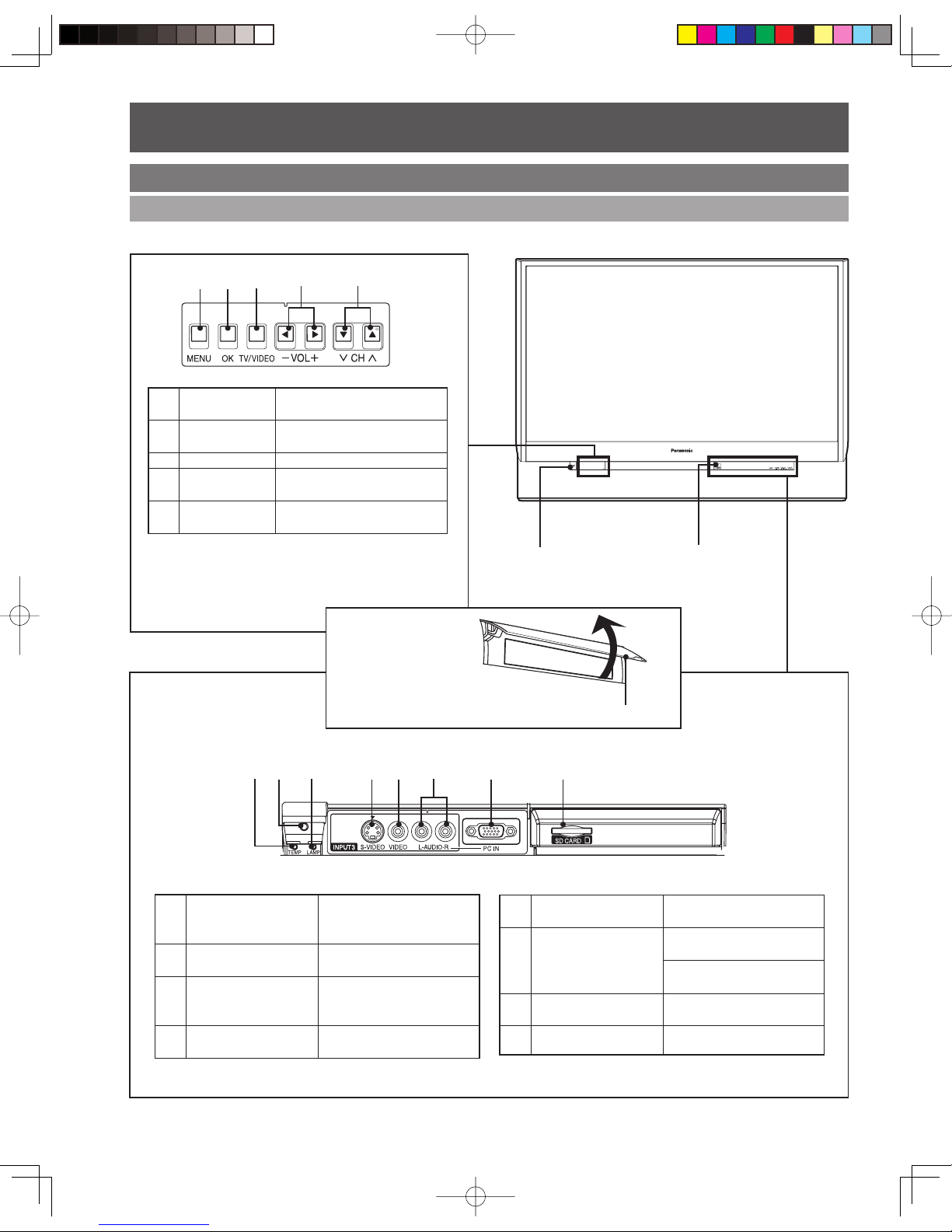
Controls and Terminals on the Projection Display
Front View <Model PT-52LCX65-K unit shown>
1
MENU
Press to display Main
Menu.
2
OK
Press to select menu and
sub-menu items.
3
TV/VIDEO Changes Input source.
4
VOL -+ / ◄►
Press to adjust TV sound
and navigate in menus.
5
CH
<
>
/ ▲▼
Press to change channels
and navigate in menus.
12 3 4 5
1
TEMP indicator
Lights up when
temperature inside unit is
abnormal. (P. 65)
2
Remote Control
Sensor
Receives infrared signal
from Remote Control.
3
LAMP indicator
Lights up when the lamp
unit is malfunctioning. (P.
65)
4
S-Video Input
Connector 3
Connect from other
component. (Video 3)
5
Video Input
Connector 3
Connect from other
component. (Video 3)
6
Audio Input
Connector (Shared
with both Video 3
and PC)
Connect from other
component. (Video 3)
Connect from PC. (PC)
7
PC (RGB) Input
Connector
Connect from PC. (PC)
8
SD CARD Slot Insert SD Card.
12 3 45 68
POWER button /
POWER indicator
Location of Controls (continued)
Remote Control
Sensor
Note:
• Buttons listed above operate the same as remote
control buttons of the same name.
7
Open
Using your finger,
slide Cover in
direction of arrow to
open.
Cover
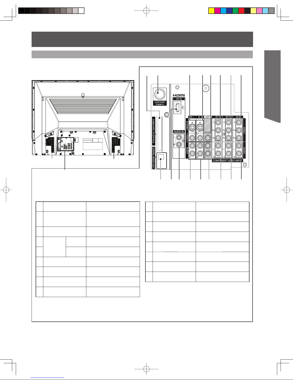
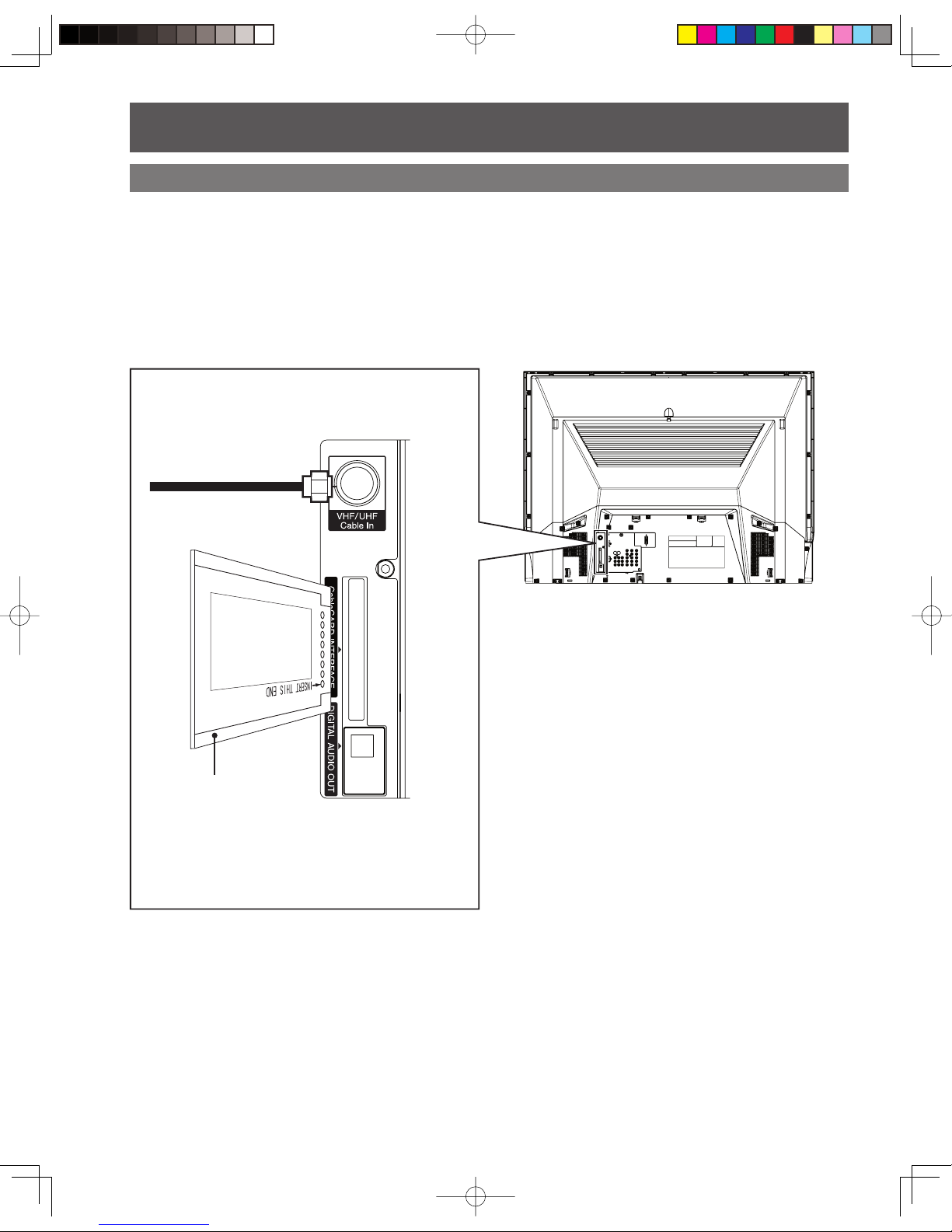
11
Getting Start ed
Vent
Notes:
• Make sure the vents are not blocked. (This could cause damage.)
• Indication on the back panel may change without notice.
Vent
1
CableCARD™
INTERFACE
Insert CableCARD™.
2
VHF/UHF Cable In
Input terminal for an
antenna or cable box
signal.
3
DIGITAL AUDIO
OUT
Output audio signal
(Digital)
4
HDMI
Input
Terminal
Audio/
Video
Connect from other
component. (HDMI)
5
Audio
Connect from other
component. (HDMI)
6
S-Video/Video Input
Connector 1
Connect from other
component. (Video 1)
7
Audio Input
Connector 1
Connect from other
component. (Video 1)
8
S-Video/Video Input
Connector 2
Connect from other
component. (Video 2)
9
Audio Input
Connector 2
Connect from other
component. (Video 2)
12
345
6 8 12 14 16
7 9 13 15 17
10
Video Out
Connector
Output video signal
11
Audio Out
Connector
Output audio signal
(Analog)
12
Component Video
Input Connector 1
Connect from other
component. (Component 1)
13
Audio Input
Connector 1
Connect from other
component. (Component 1)
14
Component Video
Input Connector 2
Connect from other
component. (Component 2)
15
Audio Input
Connector 2
Connect from other
component. (Component 2)
16
Component Video
Input Connector 3
Connect from other
component. (Component 3)
17
Audio Input
Connector 3
Connect from other
component. (Component 3)
10
11
Rear View <Model PT-52LCX65-K unit shown>
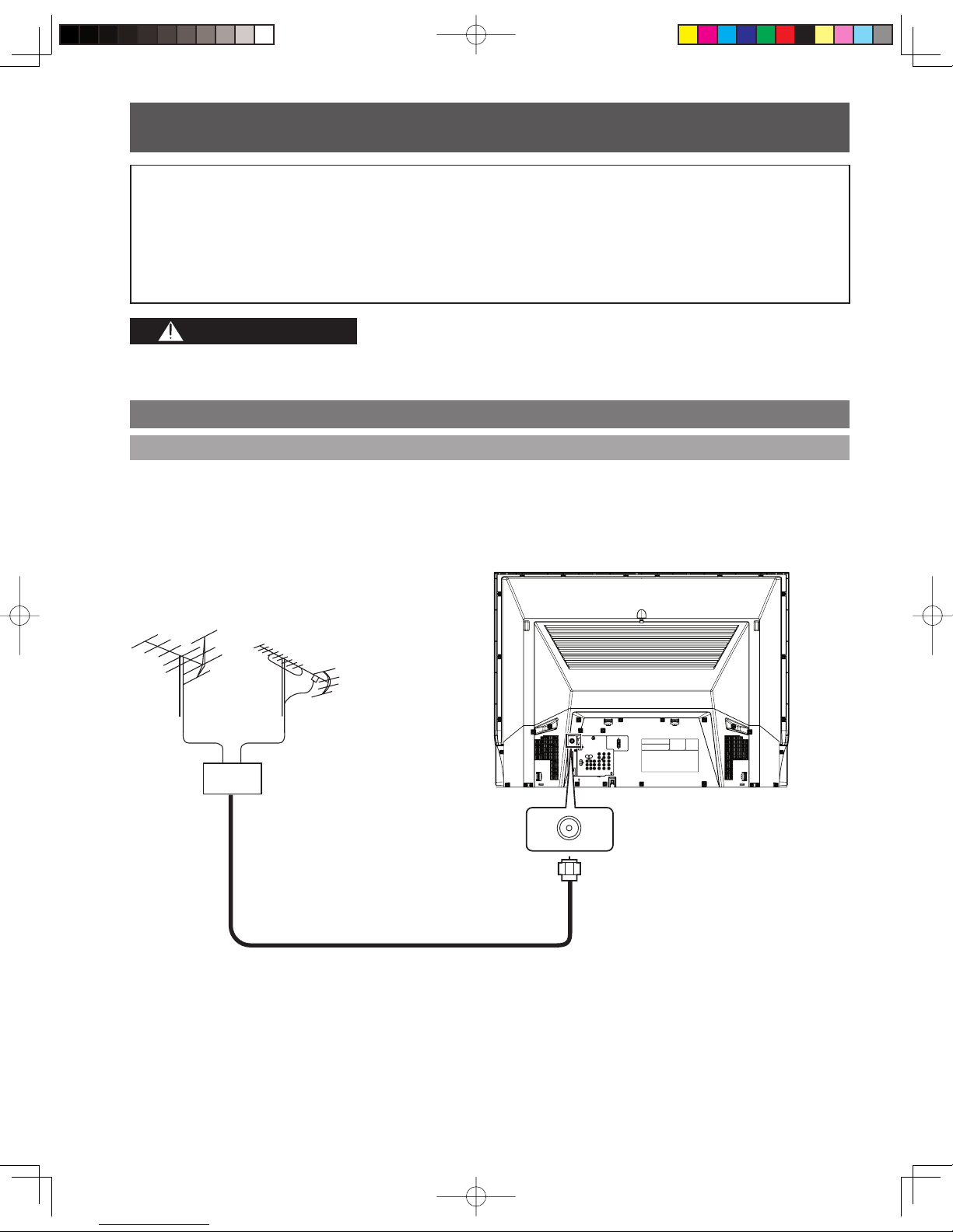
12
Antenna Connection
VHF/UHF Cable In terminal on the
back of the Projection Display
Connecting the Antenna / Cable to the RF IN Terminal
When using “Nut type” RF coaxial cable, tighten with fingers only. Overtightening may damage terminal.
• Turn off the power supply for all com po nents before making any connections.
• If the cables necessary for connecting a component to the system are not included with the component or available as an
option, you may need to fashion a cable to suit the component concerned.
• Read the instruction manual for each system component care ful ly before connecting it.
• If there is a lot of jitter in the video signal input from the video source, the picture on the screen may flicker. In this case, it will
be necessary to connect a TBC (time base corrector).
Notes on con nec tions
CAUTION
Mixer
Installation
For proper reception of digital and analog VHF/UHF channels, an external antenna is required. For best reception, an
outdoor antenna is recommended.
VHF Antenna UHF Antenna
RF Coaxial Cable
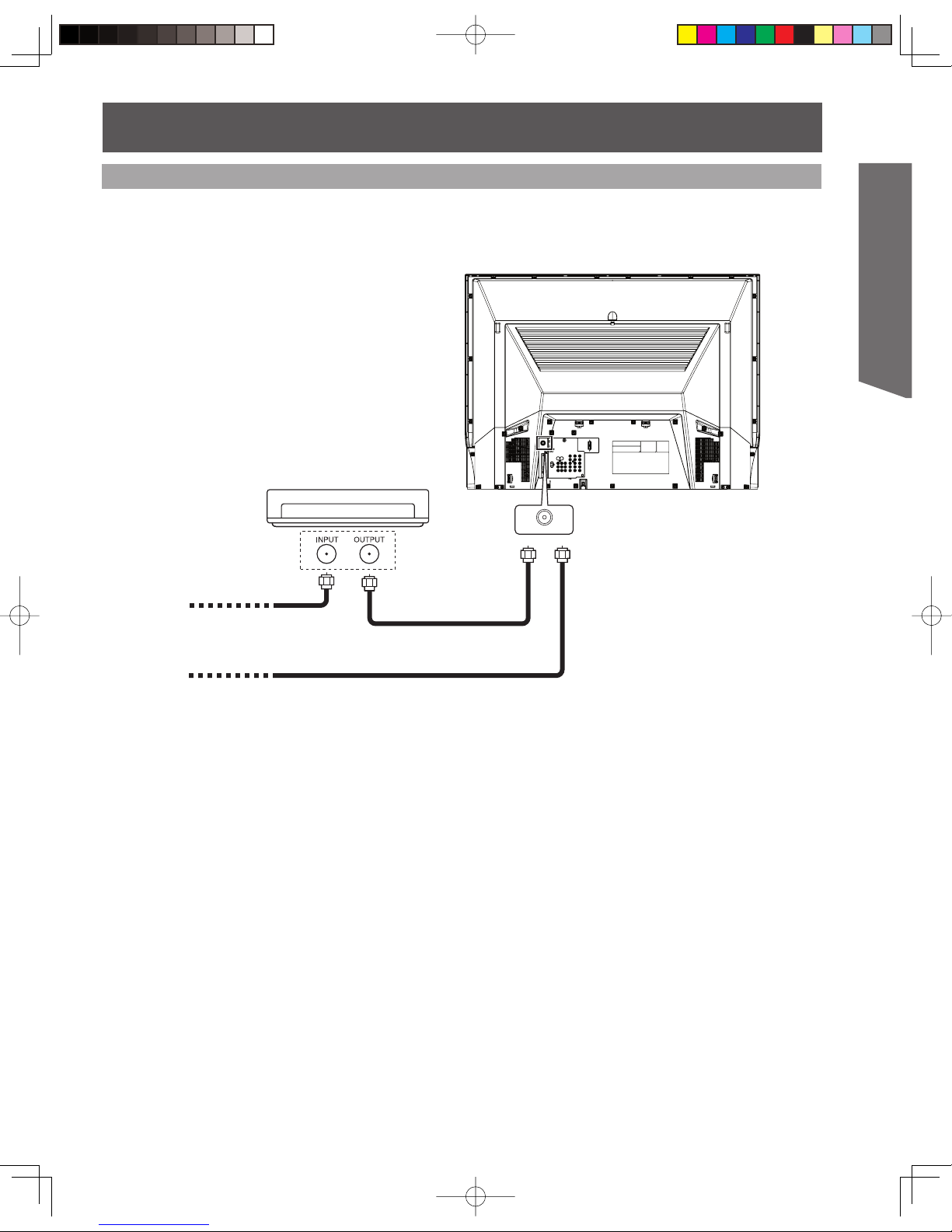
13
Getting Start ed
For proper reception of analog or digital cable channels, a cable service connection is required.
Cable Connection
Cable Box
Terminal on the back of the
Cable Box
In from cable
Connect the cable from the antenna or
cable system to the VHF/UHF Cable In
terminal on the back of the Projection
Display.
Or
In from cable
Use this confi guration when connecting the projection display to a cable TV system.
Notes:
• Certain cable systems offset some channels to reduce interference or have Premium (scrambled) channels. A cable converter
box may be required for proper reception. Check with your local cable company for its compatibility requirements.
• For reception of cable channels, connect the cable supplied by your local cable company.
14
CableCARDTM Connection
This module (also called Point of Deployment (POD) module or Digital Cable Module (DCM)) allows you to
tune digital and high definition cable channels through the cable antenna. Contact your local cable company
for information regarding the availability and costs of CableCARDTM related services.
Notes:
• A Digital Cable Subscription is required.
• Do not insert a PC card into the CableCARDTM INTERFACE.
• Follow the instructions on screen.
In from cable
1 Connect the cable antenna to the VHF/UHF Cable input on the back of the unit.
2 Insert the CableCARD
TM
(label side facing left) into the CableCARDTM INTERFACE on the back of the unit.
If you experience keyboard or remote control function hang-up when using CableCARDTM, unplug the unit and plug it
back in and try the controls again. If this condition still exists, please call Panasonic Customer Call Center for further
instructions.
CableCARD
TM
Installation (continued)
15
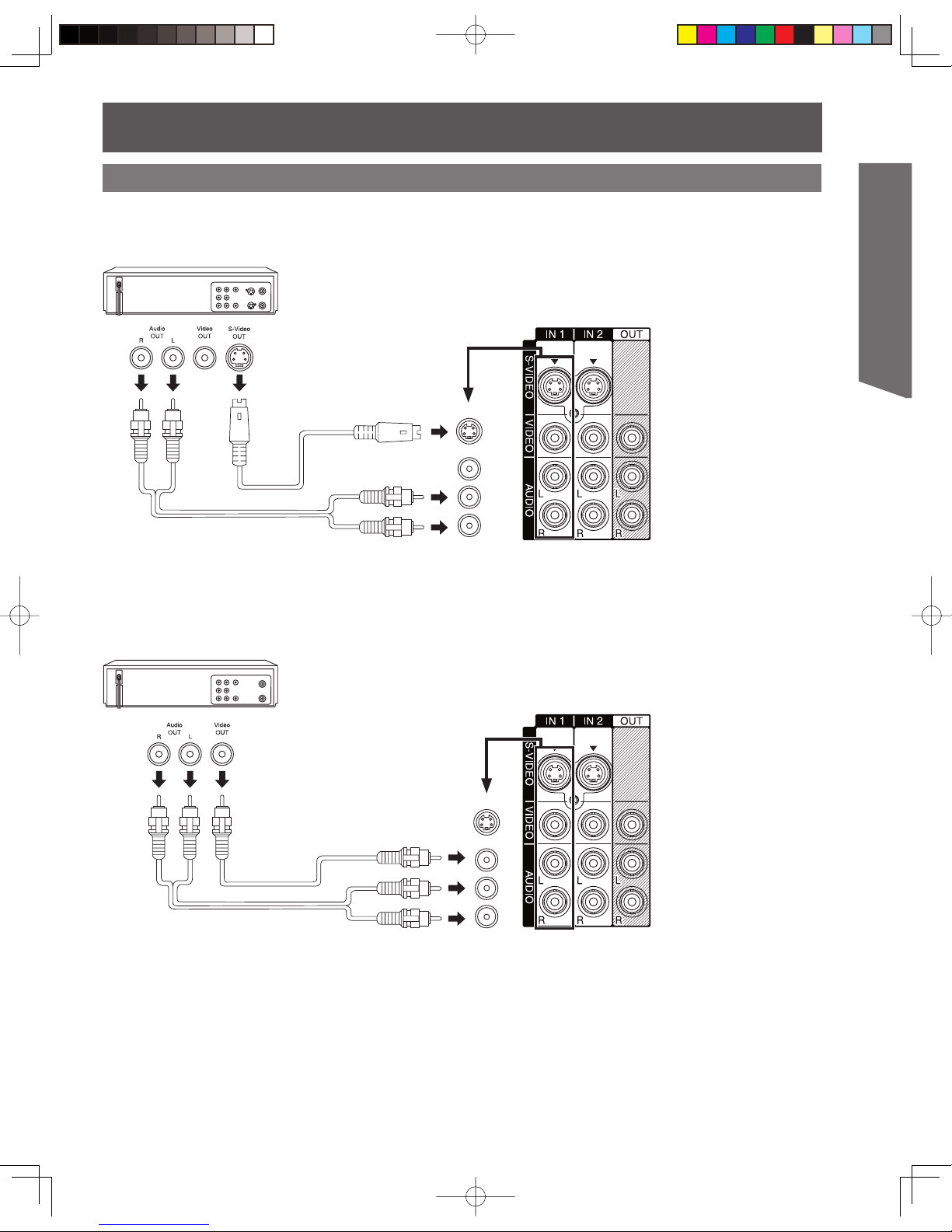
Getting Start ed
How to connect to Input Terminals 1, 2 and 3
Connect a VCR or other peripheral equipment
Similar connections are available at input terminals 1-3.
(PP. 10-11)
Notes:
• Input 3 is located on the front of the unit. (P. 10)
• Select the desired VIDEO input position by pressing the TV/VIDEO button. (P. 32)
• When connecting video cables, priority is given to the S-Video cable when the S-Video input terminal and the video input
terminal are connected at the same time.
Similar connections are available at input terminals 1-3.
(PP. 10-11)
(S-VHS VCR)
S-VIDEO
AUDIO
(VHS VCR)
VIDEO
AUDIO
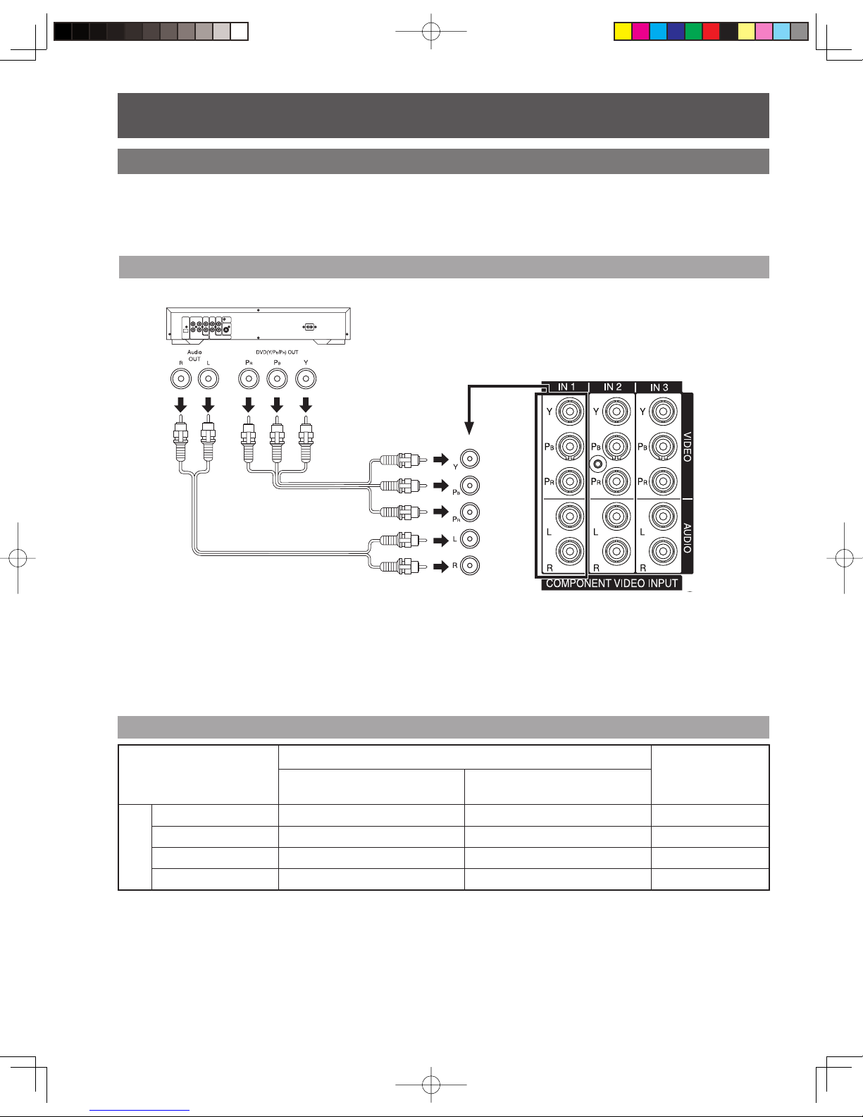
16
How to con nect the COMPONENT VIDEO Input Terminals
Notes:
• Select the desired COMPONENT VIDEO INPUT position by pressing the TV/VIDEO button. (P. 32)
• Component video signals that will be recognized are 480i, 480p, 720p, and 1080i.
Because each Y, PB, and PR signal is input independently, the Component signal allows for more accurate
color reproduction.
Please refer to the operating instructions for the jack configuration, of the DVD Player or other device, to be
connected to this unit.
DVD Player
COMPONENT VIDEO
AUDIO
Mode type
Signal data
Information menu
display
No. of dots
(H × V)
Vertical frequency
(Hz)
DTV Format
Signals
480i 720 × 480 59.94/60.00 480i
480p
720 × 480 59.94/60.00 480p
720p 1 280 × 720
59.94/60.00 720p
* 1080i 1 920 × 1 080
59.94/60.00 1080i
Component Signals (Y, PB, PR) that can be Input
Note:
• Input signals, other than those listed with a * mark, will give you a beautiful, stable picture.
Connecting a DVD Player to COMPONENT VIDEO IN
Installation (continued)
Similar connections are available at the COMPONENT VIDEO INPUT Terminals 1-3.
(PP. 10-11)
* Signal will be compressed to fit the display.
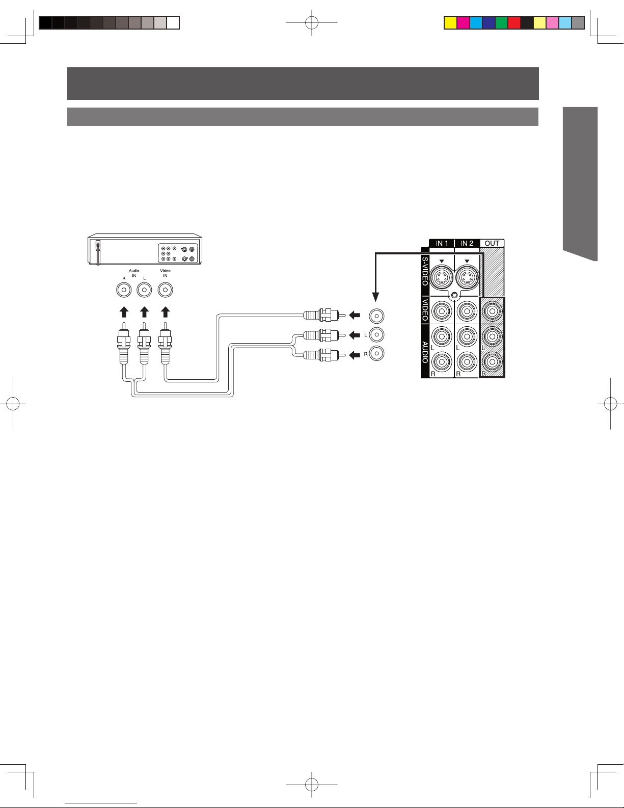
17
Getting Start ed
How to connect the AV OUT Terminals
Recording Equipment
(S-VHS /VHS VCR)
VIDEO
AUDIO
You can connect a VCR to the AV OUT terminal to record the program you are viewing on-screen. An
external monitor can also be connected to the AV OUT terminals. Connect the VCR as shown below.
Notes:
• This unit contains Video and Audio Outputs for the purpose of recording television programming to VCR. Due to license
restrictions, if a device (STB, DVD, etc.) is connected to the HDMI input of the unit, no video or audio output is allowed.
• AV Out signal is available when receiving digital channel. However, all formats will be down converted to NTSC.
• Never connect the VIDEO IN and OUT terminals to the same video recorder, as this could cause incorrect operation.
• Even if unit is in Split mode, OUT terminals only output the main picture and sound signals. A sub-picture, etc., will not be output.
• AV terminals will not output Y, PB, PR, PC/HDMI IN or SD card signals.
• Certain program content output from the AV Out connector may have the Macrovision signal modification applied to its signal,
preventing VCRs from recording this video signal.
18
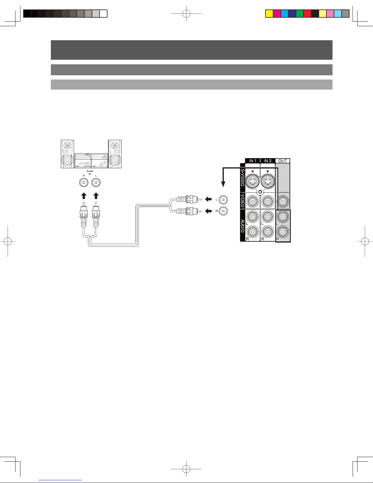
How to connect the Amplifier
Analog Audio Out
Stereo System
(A Stereo Amplifier and Speakers)
AUDIO
To listen to the audio through a separate stereo system, connect an external audio amplifier to AUDIO OUT
on back of unit.
Notes:
• AUDIO OUT terminals cannot be connected directly to external speakers.
• Analog Audio output terminals will not output HDMI Audio signals.
Audio Adjustments
• Select Speakers Off in Other Adjust menu under Audio menu. (See page 43.)
• Set amplifier volume to the preferred level.
Installation (continued)
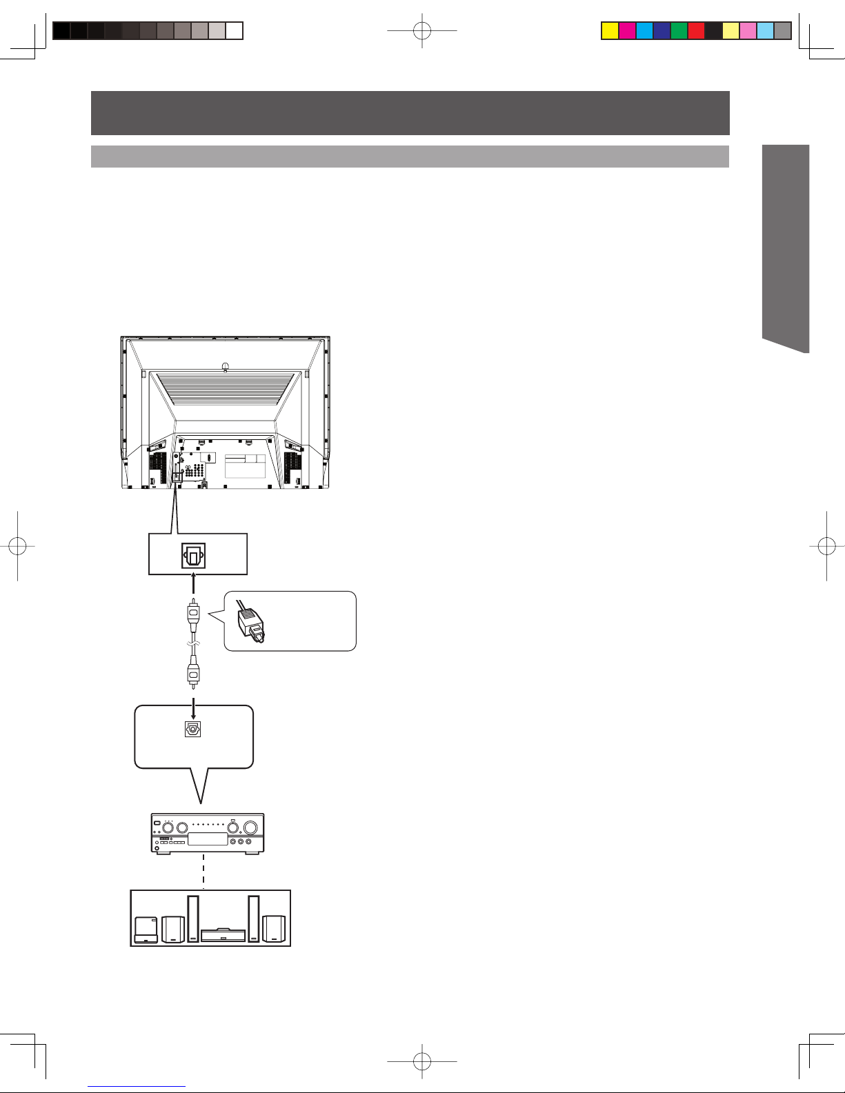
19
Getting Start ed
/04)#!,
Firmly connect
the cable to
the connector.
Connect three or
more speakers for
surround sound.
Speakers (example)
Use the diagram below to connect the Digital Audio Output of your Projection Display to a Dolby Digital
decoder.
Dolby Digital 5.1 channel surround sound delivers digital-quality sound. Dolby Digital provides five discrete
full-bandwidth channels for front left, front right, center, surround left and surround right, plus a LFE (Low Frequency
Effect) subwoofer channel, For a full Home Theater sound experience, an external Dolby Digital decoder and a
multichannel amplifier must be connected to the Digital Audio Out jack on the unit.
Procedure
Connect the Digital Audio cable from the Digital Audio
Out jack on the unit to the Digital Audio In connection on
the Dolby Digital decoder.
Notes:
• When ATSC channel is selected, the output from the Digital
Audio Out jack will be Dolby Digital. But, if NTSC channel is
selected, the output will be PCM.
• Depending on your DVD player and DVD-Audio software the
copyright protection function may operate and disable optical
output.
Digital Audio Out
Amplifier with built in Dolby
Digital decoders.
20
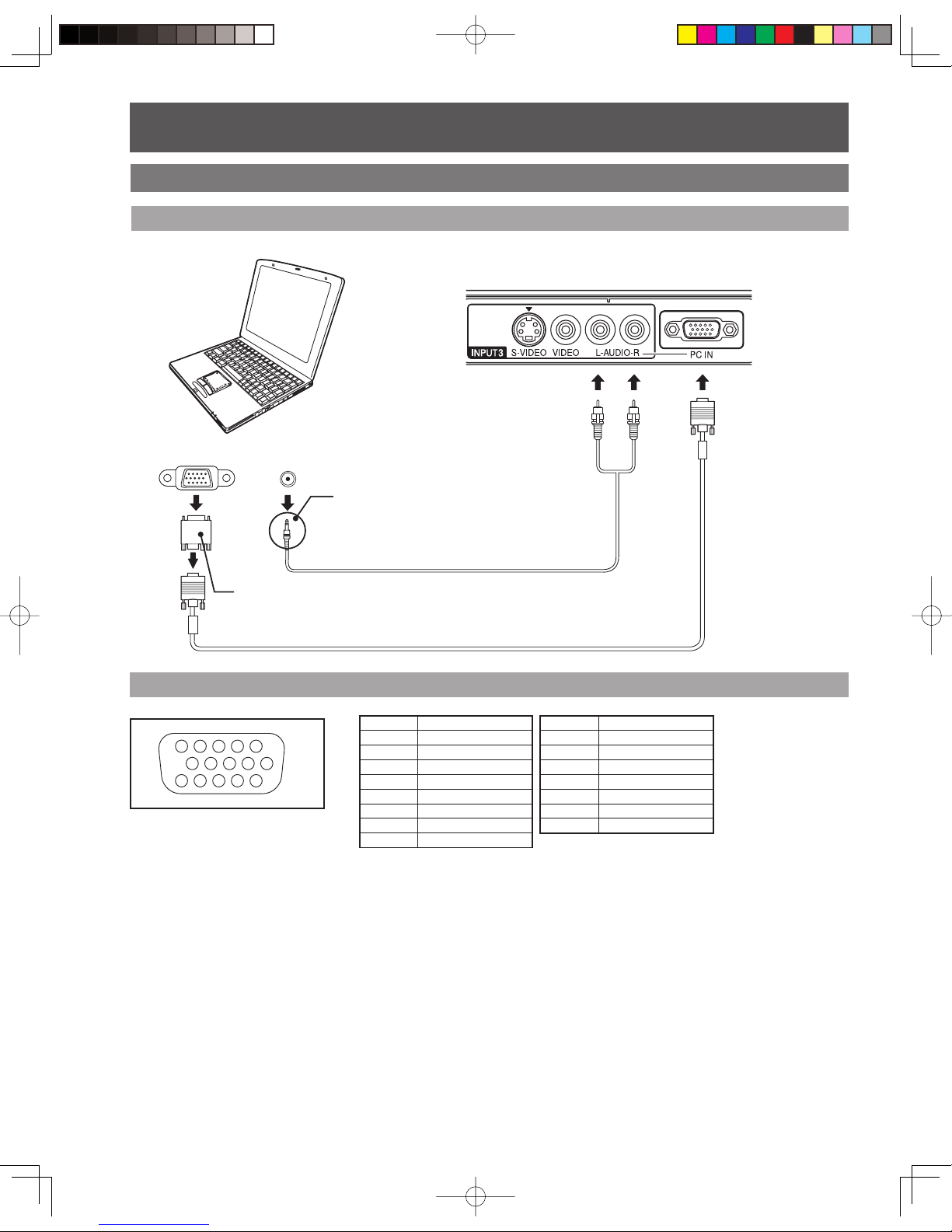
RGB OUT AUDIO OUT
COMPUTER
How to connect the PC IN Terminals
Notes:
• Some PC models cannot be connected to the set. A conversion adapter is required to use the RGB cable (D-SUB 15P) (Not
included) to connect a Macintosh computer to the set. There is no need to use an adapter for computers with PC / AT compatible
D-SUB 15P terminal.
• The computer shown in the illustration is for example purposes only. Additional equipment and cables shown are not supplied
with this set.
• The picture will become dark if a PC signal with a vertical scanning frequency of 62 Hz is input. To obtain the optimum picture
quality with the Projection Display, a vertical scanning frequency of 60 Hz is recommended.
• Do not set the horizontal and vertical scanning frequencies for PC signals which are above or below the specified frequency
range.
• Select the desired PC input position by pressing the TV/VIDEO button. (P. 32)
• AUDIO IN is shared with VIDEO 3 input.
Pin No. Signal name
1R
2G
3B
4NC
5NC
6 Ground for R
7 Ground for G
8 Ground for B
1
67839
45
10
15 14 13 12 11
2
NC: Not connected
Pin No. Signal name
9NC
10 Ground
11 NC
12 NC
13 HD/CSYNC
14 VD
15 NC
Audio cable
(M3 stereo mini pin-PIN cable)
Connect a cable which matches the audio
output terminal on the computer.
Conversion adapter
(If necessary)
RGB cable (D-SUB 15P) (Not included)
PC IN Terminal (D-SUB 15P) Pin Layouts
Connection port view
Connecting a PC to PC IN
Installation (continued)
21
Getting Start ed
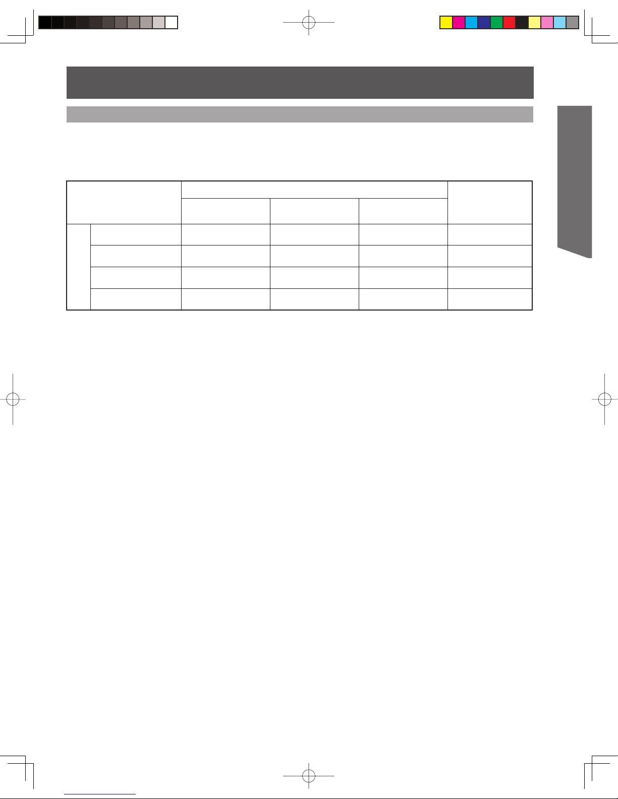
RGB signals that can be input
The table below lists the different types of RGB signals that can be input.
If a signal which differs greatly from the types listed below is input, the picture may not be displayed
correctly, or a black background may be displayed. In this case, “signal” will flash on-screen for about 5
seconds.
Notes:
• Input signals, other than those listed with a * mark, will give you a beautiful, stable picture.
• The D-SUB15P connector can accept RGB (H-V sync separate).
• When an external video processor/scaler is used, it must have RGB (H-V sync separate) output.
Mode type
Signal data
Information menu
display
No. of dots
(H × V)
Horizontal frequency
(kHz)
Vertical frequency
(Hz)
Personal Computer
Signals
VGA400 (70 Hz) 640 × 400 31.47 70.08 VGA400
VGA480 (60 Hz) 640 × 480 31.47 59.94 VGA
SVGA (60 Hz) 800 × 600 37.88 60.32 SVGA
* XGA (60 Hz) 1 024 × 768 48.36 60.00 XGA
* Signal will be compressed to fit the display.
22
AUDIO OUT
HDMI OUT
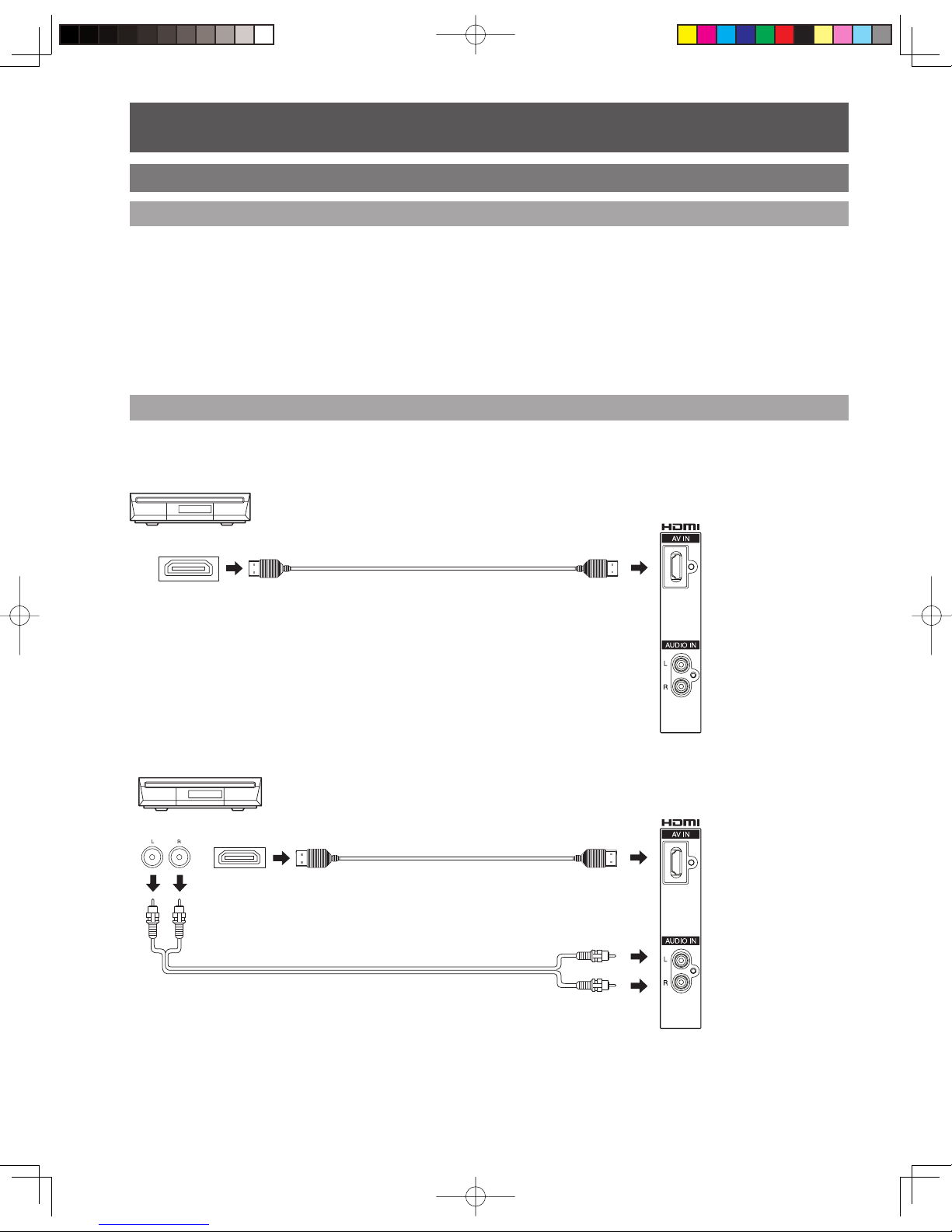
How to connect the HDMI input terminal
HDMI OUT
The connector on the unit is an HDMI
Type A connector.
The connector on the unit is an HDMI
Type A connector.
HDMI is the first all digital consumer electronics A/V interface that supports several uncompressed standards,
enhanced and high definition video formats as well as all existing multi-channel audio formats. One jack supports
both video and audio information. The HDMI/HDCP*
1
input can be connected to an EIA/CEA 861/861B*2 compliant
consumer electronic device, such as a set top box or DVD player equipped with a HDMI output connection. By
inputting a High-bandwidth Digital Content Protection (HDCP) high definition picture source to the HDMI terminal of
this unit, high definition pictures can be displayed on the screen in their digital form. The HDMI input terminal is not
intended to be used with personal computers. This unit is compatible with
1080i, 720p, 480p and 480i formats. Select
the output of the connected device to match that of the unit.
Notes:
*1
HDMI/HDCP = High Definition Multimedia Interface / High-Bandwidth Digital Copy Protection.
*2
EIA/CEA-861/861B Profiles compliance covers profiles for transmission of uncompressed digital video including high bandwidth
digital content protection.
Follow the diagram below to connect the unit to a set top box or a DVD player.
Set top box
Set top box
When the audio signal is digital.
When the audio signal is analog.
About HDMI
Connection diagram
Installation (continued)
23
Getting Start ed
By inputting a High-bandwidth Digital Content Protection high-definition picture source to the HDMI IN terminal of this
Projection Display, high-definition pictures can be displayed on the screen in their digital form. (This terminal is for
use with HDMI equipped DVD players, Set top boxes and D-VHS machines.)
Notes:
• Select the HDMI input position by pressing the TV/VIDEO button. (P. 32)
• The HDMI IN terminal can only be used with 1080i, 720p, 480p and 480i picture signals.
• If there is no audio, check if the source equipment has PCM output. If not, please use analog connections.
• Be sure HDMI is securely connected. If not, picture noise and/or incorrect picture display may result.
• With HDMI connection, depending on the signal, the picture may be displayed with unnatural colors (as if red and blue are
reversed). Refer to “Color Corr.” on page 41.
Procedure
When digital audio is included in the HDMI connection, the compatible sampling frequencies are 48 kHz/44.1 kHz/
32 kHz. Refer to “HDMI In” on page 43.
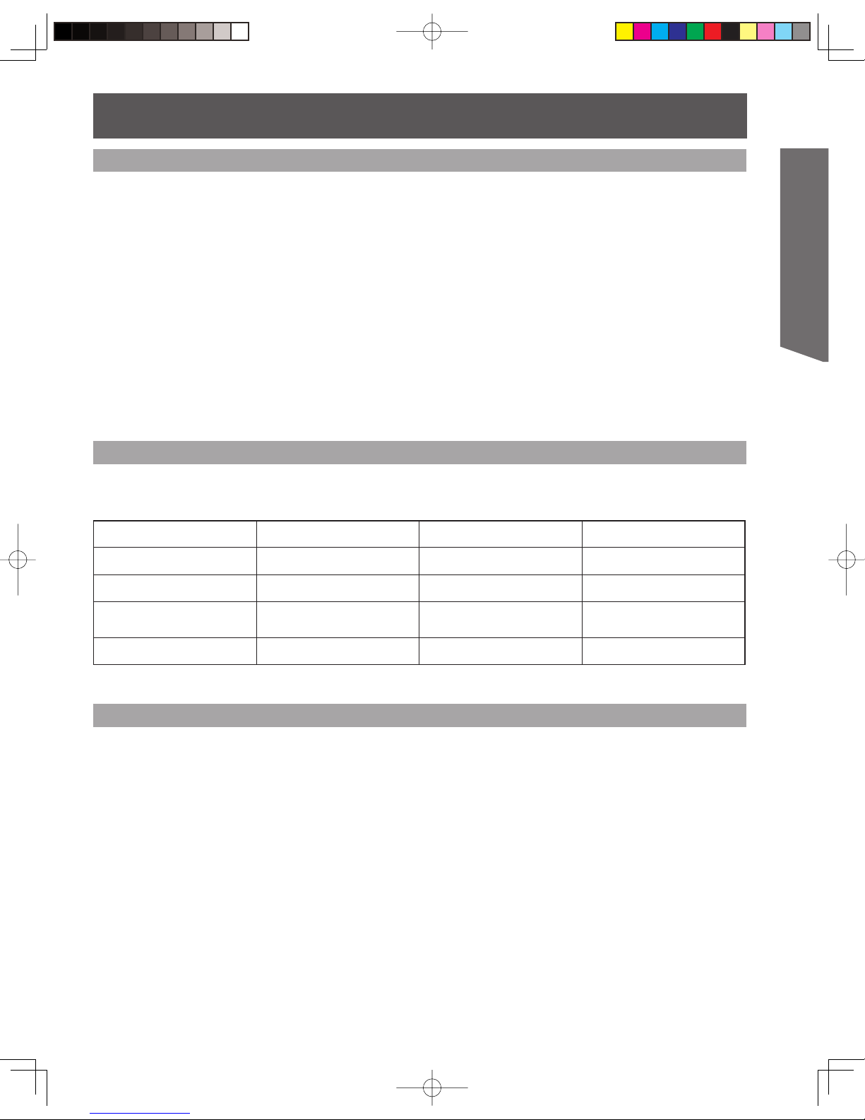
Video Signal:
The Projection Display is compatible with following formats. Please set the connected device to one of the following
formats.
Display mode No. of dots
Vertical scanning frequency
(Hz)
Information menu display
1080i 1920 × 1080 59.94 / 60 1080i
720p 1280 × 720 59.94 / 60 720p
480p
720 × 480
640 × 480
59.94 / 60
59.94 / 60
480p
480i 720 × 480 59.94 / 60 480i
• If you cannot display the picture because your Digital Set Top Box does not have a Digital Out terminal setting, use the
Component Video Input (or the S-Video Input or Video Input). In this case, the picture will be displayed as an analog signal.
2 Press TV/VIDEO to select HDMI input.
1 Connect the HDMI output from the set top box or a DVD player to the HDMI input on the back of the unit.
Compatible formats
Audio signal ( PCM)
24
POWER
SAP
LIGHT
MENU
123
4
5
6
7809
RETURN
CH
CH
VOL VOL
R-TUNE
REW
TV/VCR
SPLIT SWAP
DVD/VCR CH
OPEN/CLOSE
PLAY
PAUS E STOP REC
FF
PROG
TV/VIDEO
SLEEP EXIT
TV VCR DVD
DTV RCVR
DBS/CBL
AUX
OK
M
U
T
E
A
S
P
E
C
T
F
A
V
O
R
I
T
E
R
E
C
A
L
L
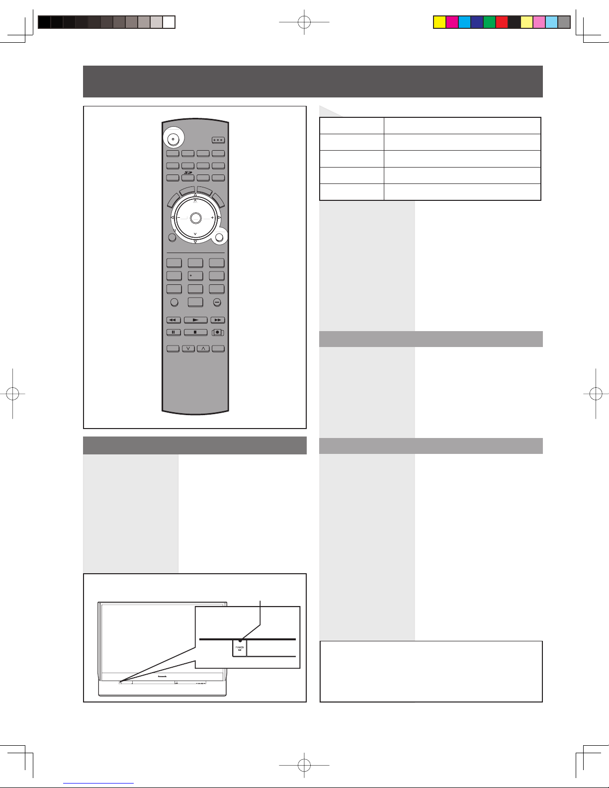
Always be sure to follow the procedure given below to
turn the Projection Display power ON and OFF.
• The lamp cooling fan will continue to operate for
approximately 1 minute after the power is turned off. During
this time
, the POWER indicator will blink Red.
Press POWER on Projection Display or Remote Control
to turn power on.
The Power Indicator blinks Green for about 20 seconds
and then turns solid Green.
The Power Indicator
Notes:
• If the POWER button is accidentally turned off during use,
after power is turned back on, it may take a short period
before the lamp automatically comes on.
• After the unit is turned on, maximum picture brightness will be
achieved in 5-10 minutes. This is normal.
• This unit consumes approx. 0.3 W (15W when CableCARDTM
is inserted.)
in OFF condition when plugged into an AC outlet.
Press POWER on Projection Display or Remote Control
to turn power off.
Note:
• When the power cord is disconnected, the internal cooling
fan stops op er at ing. In this case, the lamp will be insufficiently
cooled and will take a while to turn ON again.
Power ON
Power OFF
The Power Indicator blinks Red for about 1 minute and
then LED turns off.
Turning the Power ON and OFF
LED ACTION
Off Power – OFF
Red (blinking)
Power – OFF (Now cooling)
Green Power – ON
Green (blinking) Power – ON (Preparing to light lamp)
Power shuts off after a Black Screen is displayed for a
few seconds.
Note:
• If the POWER button is pressed during the Black Screen
display, Power is turned back on.
Do not disconnect the power cord from the outlet
and do not open the circuit breaker (unless
necessary) while the cooling fan is still operating. Do
not disconnect the power cord from the power outlet
while the power indicator blinks Red.
POWE
R
Power ON / OFF
Auto shut off
To extend lamp life, if there is no signal to the
set’s tuner for 5 minutes, the lamp will shut off
automatically.
POWER button/
POWER indicator
U
RETURN
CH
CH
V
OL VOL
O
K
25
Basic Operation
For your convenience, First Time Set up menu will
be displayed on screen when the set is turned on
for the first time. If needed, follow the menus and
procedures displayed on-screen for setting up the
features.
Auto program
You can scan All (Analog and Digital) channels. If
needed, follow the menus and procedures displayed
on-screen for setting up the features. You can also make
the settings in Setup menu.
Notes:
• After “Auto program” is completed the unit tunes to the first
channel found during “Auto program”.
• If setup is incomplete, check connection of Antenna/Cable to
the RF IN Terminal, then try “Auto program” again. (p. 29).
• “Auto program” must be done when you select the input
signal for the first time or whenever you change the antenna
configuration.
• Depending on conditions, “Auto program” may take a while.
First Time Setup
Language
The language of the on-screen display is set to English
as the factory setting.
You can select English, Spanish or French as the
on-screen display language.
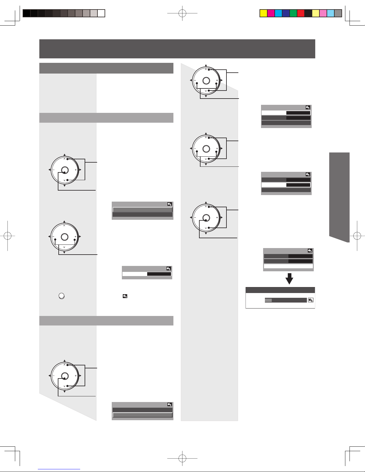
Press to select “Language”.
First time setup
Language
Auto program
Language
Language ◄ English►
Press to display Language
screen.
1
CH
CH
VOL VOL
OK
CH
CH
VOL VOL
OK
Press to select “English,”
“Español” or “Français”.
2
3
Press to go to previous screen.
Or, select
icon, then press
OK for same results.
Auto program
ANT In ◄ Cable ►
Mode All
Start scan
Press to select “ANT In”.
Press to select “Cable” or
“Antenna”.
2
CH
CH
VOL VOL
OK
Press to select Mode.
Press to select “All” or
“Analog”.
3
Auto program
ANT In Cable
Mode ◄ All ►
Start scan
CH
CH
VOL VOL
OK
CH
CH
VOL VOL
OK
4
Press to select “Start scan”.
Press to start.
Channels available for
reception will be set
automatically.
Auto program
ANT In Cable
Mode All
Start scan
Now scanning analog channel ...
Progress
5
RETURN
After Auto Program is complete, the unit will return
to Manual Program mode. To place the channels
that were located by auto scan in memory, move the
cursor to “Apply” and press OK.(pp. 30-31).
If OK is not pressed after selecting OK, the channels
will not be memorized.
First time setup
Language
Auto program
Press to select “Auto program”.
Press to display Auto program
screen.
1
CH
CH
VOL VOL
OK
26
POWER
SAP
LIGHT
MENU
123
4
5
6
7809
RETURN
CH
CH
VOL VOL
R-TUNE
REW
TV/VCR
SPLIT SWAP
DVD/VCR CH
OPEN/CLOSE
PLAY
PAUS E STOP REC
FF
PROG
TV/VIDEO
SLEEP EXIT
TV VCR DVD
DTV RCVR
DBS/CBL
AUX
OK
M
U
T
E
A
S
P
E
C
T
F
A
V
O
R
I
T
E
R
E
C
A
L
L
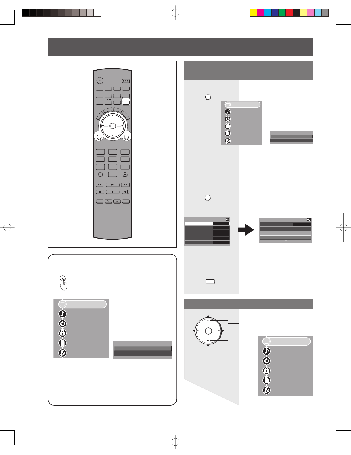
Pressing MENU displays the Main
Menu screen.
Press to select the desired
icon.
Press to return to previous level menu.
Press
EXIT
MENU
RETURN
Press to display Main menu.
Picture
Audio
Timer
Lock
Memory Card
Setup
Picture
Color Temp Normal
PC Adjust
Other Adjust
Adv. Adjust
Example:
If RETURN is pressed from Adv. Adjust Menu:
Adv. Adjust
Normal No
Gamma Adj. Full
Blk. Extension +10
R Level +10
G Level +10
B Level +10
Picture
Audio
Timer
Lock
Memory Card
Setup
Button operation during
Menu display (Menu navigation)
to exit menu.
Basic Menu Navigation
Example of a procedure
Depending on the signal being input, some
items may or may not be adjustable and some
functions may or may not be available.
Note:
• While Main Menu (only) is displayed, pressing MENU will exit
the menu screen.
MENU
Picture
Audio
Timer
Lock
Memory Card
Setup
Return to normal picture.
Return to previous level menu.
Return to Main Menu.
CH
CH
VOL VOL
OK
1
EXIT
MENU
R
ETUR
N
CH
CH
V
OL VOL
O
K
Menu
Picture
Audio
(PC input menu)
Menu
Picture
Audio
(PC input menu)
27
Basic Operation
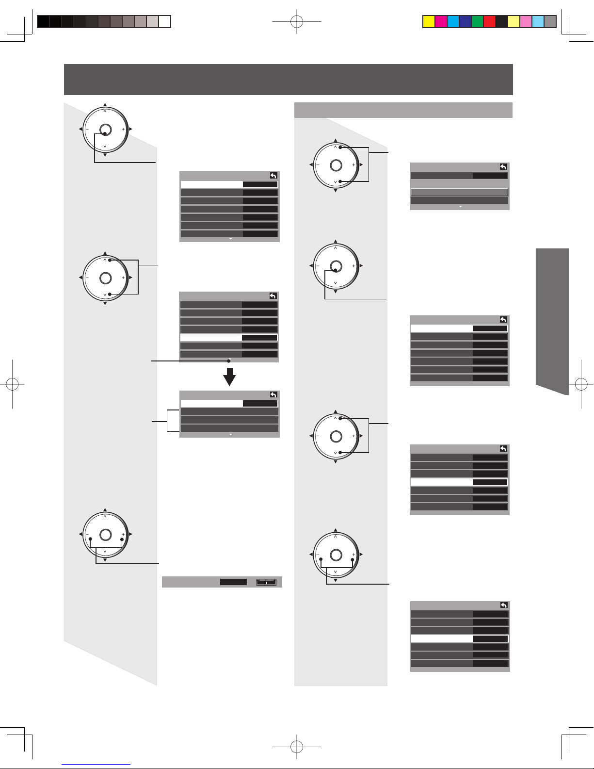
Picture
Normal No
Pic. Mode Vivid
Picture +10
Brightness +10
Color +10
Tint +10
Sharpness +10
Picture
Normal No
Pic. Mode Vivid
Picture +10
Brightness +10
Color +10
Tint +10
Sharpness +10
Press to enter the menu.
Press to select desired menu
item.
Press to adjust or set desired
menu item.
Other Adjust sub-menu.
Press to select Other Adjust.
Press to access Other Adjust
sub-menu.
Press to select desired
sub-menu items.
Press to adjust or set desired
menu item.
Color +5
Sub Menu Field
Next Icon
Other Adjust
Video NR On
3D Y/C Filter On
Color Matrix SD
MPEG NR On
Black Level Light
3D I/P On
Color Corr. On
Other Adjust
Video NR On
3D Y/C Filter On
Color Matrix SD
MPEG NR On
Black Level Light
3D I/P On
Color Corr. On
Other Adjust
Video NR On
3D Y/C Filter On
Color Matrix SD
MPEG NR Off
Black Level Light
3D I/P On
Color Corr. On
Picture
Color Temp Normal
PC Adjust
Other Adjust
Adv. Adjust
Picture
Color Temp Normal
PC Adjust
Other Adjust
Adv. Adjust
A Next Icon means there are more menu items
to view.
CH
CH
VOL VOL
OK
CH
CH
VOL VOL
OK
CH
CH
VOL VOL
OK
CH
CH
VOL VOL
OK
CH
CH
VOL VOL
OK
CH
CH
VOL VOL
OK
CH
CH
VOL VOL
OK
2
3
4
5
6
7
8
28
POWER
SAP
LIGHT
MENU
123
4
5
6
7809
RETURN
CH
CH
VOL VOL
R-TUNE
REW
TV/VCR
SPLIT SWAP
DVD/VCR CH
OPEN/CLOSE
PLAY
PAUS E STOP REC
FF
PROG
TV/VIDEO
SLEEP EXIT
TV VCR DVD
DTV RCVR
DBS/CBL
AUX
OK
M
U
T
E
A
S
P
E
C
T
F
A
V
O
R
I
T
E
R
E
C
A
L
L
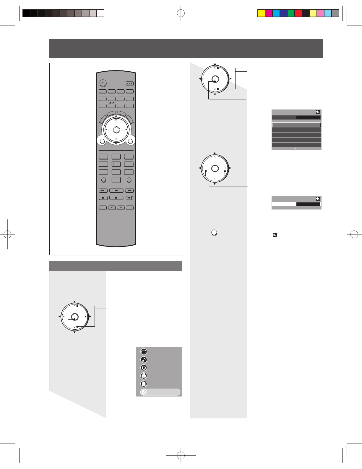
Tuning channels
Switching languages for display
Allows you to select the language used for On
Screen Displays.
Press MENU to display the Main Menu screen.
Press to select “Setup” icon.
Press to display the Setup
menu.
1
Picture
Audio
Timer
Lock
Memory Card
Setup
CH
CH
VOL VOL
OK
Setup
CH scan All
Language
Program channel
Input labels
CC
Other adjust
Language
Language ◄ English►
Press to select “Language”.
Press to display Language
screen.
2
CH
CH
VOL VOL
OK
CH
CH
VOL VOL
OK
3
Press to select “English,”
“Español” or “Français”.
4
RETURN
Press to go to previous screen.
Or, select icon, then press
OK for same results.
MENU
R
ETUR
N
CH
CH
V
OL VOL
O
K
29
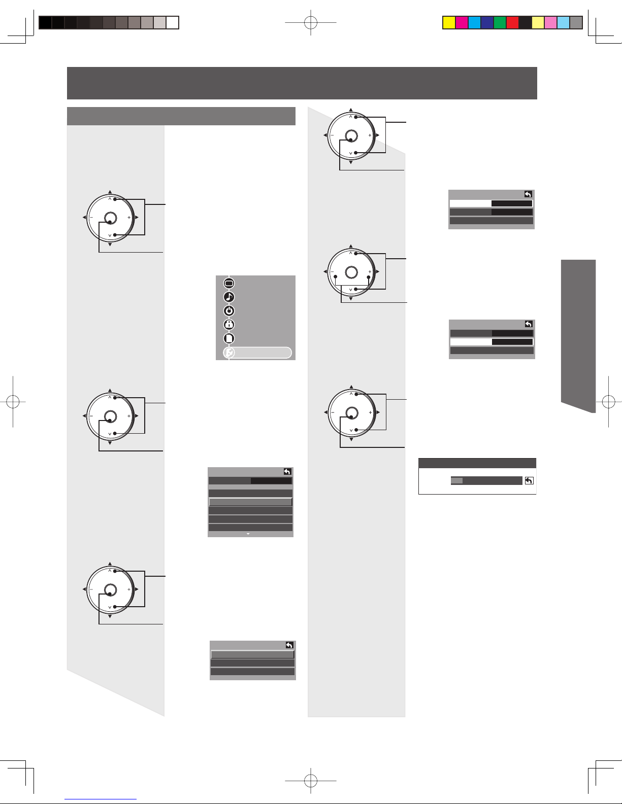
Basic Operation
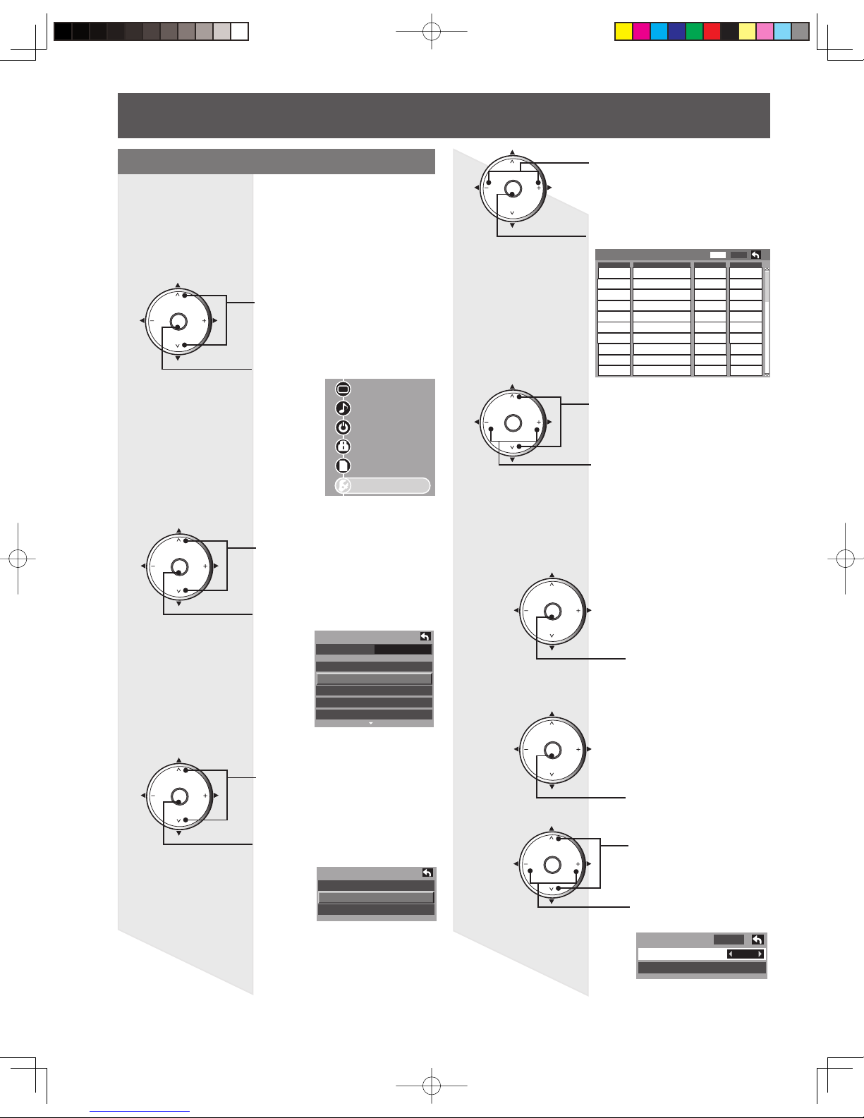
Automatically searches and adds receivable
channels to memory.
Press MENU to display the Main Menu screen.
Press to select “Setup” icon.
Press to display the Setup
menu.
Press to display the Program
channel menu.
Press to select “Program
channel”.
Press to select “Auto”.
1
Automatic program setting
2
3
Press to enter the Auto menu.
Notes:
• If “Cable” or “Antenna” is selected and a CableCARDTM is not
inserted, Auto program will perform Scan All.
• If “Cable” is selected and a CableCARDTM is inserted, Auto
scan will not be possible.
• Some channels with very weak signals may be locked into
memory. If desired, these channels can be deleted man u al ly
using the “Manual program setting”. (P. 30)
• “Auto program” must be done when you select the input
signal for the first time or whenever you change the antenna
configuration.
Press to select “ANT In”.
4
Press to select “Antenna” or
“Cable”.
Press to select “Mode”.
5
Press to select “All” or “Analog”.
Press to start Scan.
Press to select “
Start scan”.
6
Picture
Audio
Timer
Lock
Memory Card
Setup
Now scanning analog channel ...
Progress
CH
CH
VOL VOL
OK
CH
CH
VOL VOL
OK
CH
CH
VOL VOL
OK
CH
CH
VOL VOL
OK
CH
CH
VOL VOL
OK
Setup
CH scan All
Language
Program channel
Input labels
CC
Other adjust
Program channel
Auto
Manual
Signal meter
Auto program
ANT In ◄ Cable ►
Mode All
Start scan
Auto program
ANT In Cable
Mode ◄ All ►
Start scan
CH
CH
VOL VOL
OK
7
After Auto program is complete, the unit will return
to Manual program mode. To place the channels
that were located by auto scan in memory, move the
cursor to “Apply” and press OK.(pp. 30-31).
If OK is not pressed after selecting OK, the channels
will not be memorized.
30
Use this procedure when changing setting of
receiving channels or changing the channel dis play.
Also, use to add or delete channels from channel list
manually.
Manual program setting
Press MENU to display the Main Menu screen.
Press to select “Setup” icon.
Press to display the Setup
menu.
Press to select “Manual”.
1
2
3
Press to enter the Manual
program screen.
Picture
Audio
Timer
Lock
Memory Card
Setup
Program channel
Auto
Manual
Signal meter
CH
CH
VOL VOL
OK
Press to display the Program
channel menu.
Press to select “Program
channel”.
CH
CH
VOL VOL
OK
Setup
CH scan All
Language
Program channel
Input labels
CC
Other adjust
CH
CH
VOL VOL
OK
Edit
CH
1
2
3
4
5
6
7
8
9
10
- - -
- - -
- - -
- - -
- - -
- - -
- - -
- - -
- - -
- - -
- - -
- - -
- - -
- - -
- - -
- - -
- - -
- - -
No
- - - - - - No
No
No
No
No
No
No
No
No
Captio
n Favorite Add
Apply
CH
CH
VOL VOL
OK
Press to select “Edit”.
Press to enter the edit mode.
CH
CH
VOL VOL
OK
Press to select the desired
preset channel line.
Press to select edit area.
“CH,” “Caption,” “Favorite,”
“Add”.
Edit (Caption)
CH
CH
VOL VOL
OK
Press to select “Preset”.
Press to select
Broadcast station.
Apply
Caption detail
----
Caption select
Preset
4
5
Preview (CH)
You can display a program by selecting it in
the small window at the top left of the screen.
Tuning channels (continued)
Note:
• If Lock (p. 45) has been set, you must enter your password to
display the Manual Program screen.
2
Press to display the
selected program.
CH
CH
VOL VOL
OK
Press to enter the
Caption select screen.
CH
CH
VOL VOL
OK
1
 Loading...