

Panasonic PT 52DL52 User Manual
POWER
E
T
U
M
R
C
V
V
T
BBE
MENU
123
456
7809
R-TUNE PROG
REW
FREEZE
TV/VCR
PIP SPLIT MOVESWAP
SAP
T
T
V
C
/
V
E
I
D
P
E
S
O
A
L
I
G
H
T
A
U
D
X
V
D
R
C
V
R
C
V
B
T
L
D
D
B
S
CH
I
O
T
N
C
A
VOL VOL
CH
RECALL
GUIDE
PAGEEXIT
PIP MAXFFPIP MIN
PLAY
REC
STOPPAUSE
PIP CH
SEARCH
VCR CH
OPEN/CLOSE
Projection Television
Operating Instructions
Model No.
PT-52DL52
English
TM
DLP
A TEXAS INSTRUMENTS TECHNOLOGY
HD
COMPATIBLE 1080 i / 720p
TV
For assistance, please call : 1-888-VIEW-PTV(843-9788)
or send e-mail to : consumerproducts@panasonic.com
or visit us at www.panasonic.com (U.S.A)
For assistance, please call : 787-750-4300
or visit us at www.panasonic.com (Puerto Rico)
For assistance, please call : 1-800-561-5505
or visit us at www.panasonic.ca (Canada)
TQBC0512-1
WARNING
RISK OF ELECTRIC SHOCK
DO NOT OPEN
WARNING: To reduce the risk of electric shock, do not remove cover or back.
No user-serviceable parts inside. Refer servicing to qualified service personnel.
The lightning flash with
arrow-head within a triangle
is intended to tell the user
that parts inside the product
are a risk of electric shock
to persons.
WARNING: To reduce the risk of fire or electric shock, do not expose this apparatus to rain or moisture.
Do not place liquid containers (flower vase, cups, cosmetics, etc.) above the set. (including on
shelves above, etc.)
WARNING: To prevent electric shock, do not remove cover. No user serviceable parts inside. Refer servicing to
qualified service personnel.
The exclamation point
within a triangle is intended
to tell the user that important
operating and servicing
instructions are in the
papers with the appliance.
The pictorial representation
of a hot surface within a
triangle is intended to tell the
user that parts inside the
product are a risk of burns
to persons.
Trademarks
DLP is a registered trademark of Texas Instruments.
•
Certain audio features of this product are manufactured under a license from Desper Products, Inc. Spatializer® and the circle-in-
•
square device are trademarks owned by Desper Products, Inc.
VGA is a trademark of International Business Machines Corporation.
•
Macintosh is a registered trademark of Apple Computer, USA.
•
S-VGA is a registered trademark of the Video Electronics Standard Association.
•
Even if no special notation has been made of company or product trademarks, these trademarks have been fully respected.
2
Manufactured under license from BBE Sound, Inc.
Licensed by BBE Sound, Inc. under USP4638258 and 4482866.
BBE and BBE symbol are registered trademarks of BBE Sound, Inc.

Important Safety Instructions
1) Read these instructions.
All the safety and operating instructions should be read before the appliance is operated.
2) Keep these instructions.
The safety and operating instructions should be retained for future reference.
3) Heed all warnings.
All warnings on the appliance and in the operating instructions should be adhered to.
4) Follow all instructions.
All operating and use instructions should be followed.
5) Do not use this apparatus near water, for example, near a bathtub, wash bowl, kitchen sink, or laundry tub, in a wet
basement, or near a swimming pool, and the like.
6) Clean only with dry cloth. Do not use liquid cleaners or aerosol cleaners. Use a dry cloth for cleaning.
7) Do not block any ventilation openings. Install in accordance with the manufacturer’s instructions.
Slots and Openings in the cabinet are provided for ventilation and to ensure reliable operation of the product and to
protect it from overheating. The openings should never be blocked by placing the product on a bed, sofa, rug, or other
similar surface.
8) Do not install near any heat sources such as radiators, heat registers, stoves, or other apparatus (including amplifiers)
that produce heat.
This product should not be placed in a built-in installation such as a bookcase or rack unless proper ventilation is
provided or the manufacturer’s instructions have been adhered to.
9) Do not defeat the safety purpose of the polarized or grounding-type plug. A polarized plug has two blades with one wider
than the other. A grounding type plug has two blades and a third grounding prong. The wide blade or the third prong are
provided for your safety. If the provided plug does not fit into your outlet, consult an electrician for replacement of the
obsolete outlet.
10) Protect the power cord from being walked on or pinched particularly at plugs, convenience receptacles, and the point
where they exit from the apparatus.
11) Only use attachments / accessories specified by the manufacturer.
12) Use only with the cart, stand, tripod, bracket, or table specified by the manufacturer, or sold with the apparatus. When
a cart is used, use caution when moving the cart / apparatus combination to avoid injury from tipover.
Quick stops, excessive force, and uneven surfaces may cause the appliance and cart combination
to overturn.
13) Unplug this apparatus during lightning storms or when unused for long periods of time.
This will prevent damage to the product due to lightning and power-line surges.
14) Refer all servicing to qualified service personnel. Servicing is required when the apparatus has been damaged in any
way, such as power-supply cord or plug is damaged, liquid has been spilled or objects have fallen into the apparatus,
the apparatus has been exposed to rain or moisture, does not operate normally, or has been dropped.
WARNING: Because the temperature of the lamp unit is elevated immediately after its use, a direct touch to it may cause
burns. After the lamp has cooled enough, replace the lamp unit.
CAUTION :
(1) This TV set is intended to be used with the following TV stand: model TY-S52DL52 for the PT-52DL52. Use with other
stands may result in the TV set becoming unstable, possibly causing injury.
(2) Slots and openings in the cabinet and the back or bottom are provided for ventilation, and to ensure reliable operation
of the projection TV and protect it from overheating. These openings must not be blocked or covered. There should be
at least 10 cm of space from these openings.
3

Dear Panasonic Customer
Welcome to the Panasonic family of customers. We hope that you will have many years of enjoyment
from your new projection television set.
To obtain maximum benefit from your set, please read these Instructions before making any adjustments,
and retain them for future reference.
Retain your purchase receipt also, and record the model number and serial number of your set in the
space provided on the back cover of these instructions.
Visit our Panasonic Web Site for USA : www.panasonic.com
for Puerto Rico : www.panasonic.com
for Canada : www.panasonic.ca
For assistance, please call : 1-888-VIEW-PTV(843-9788)
or send e-mail to : consumerproducts@panasonic.com
or visit us at www.panasonic.com (U.S.A)
For assistance, please call : 787-750-4300
or visit us at www.panasonic.com (Puerto Rico)
For assistance, please call : 1-800-561-5505
or visit us at www.panasonic.ca (Canada)
Notice: [ For USA only]
This product has a High Intensity Discharge (HID) lamp that contains a small amount of mercury . It also contains lead
in some components. Disposal of these materials may be regulated in your community due to environmental
considerations. For disposal or recycling information please contact your local authorities, or the Electronics Industries
Alliance: <http:// www.eiae.org.>
FCC STATEMENT:
NOTE: This equipment has been tested and found to comply with the limits for a Class B digital device, pursuant to Part 15 of the FCC
Rules. These limits are designed to provide reasonable protection against harmful interference in a residential installation. This
equipment generates, uses and can radiate radio frequency energy and, if not installed and used in accordance with the
instructions, may cause harmful interference to radio communications. However, there is no guarantee that interference will not
occur in a particular installation. If this equipment does cause harmful interference to radio or television reception, which can be
determined by turning the equipment off and on, the user is encouraged to try to correct the interference by one or more of the
following measures:
Reorient or relocate the receiving antenna.
•
Increase the separation between the equipment and receiver.
•
Connect the equipment into an outlet on a circuit different from that to which the receiver is connected.
•
Consult the dealer or an experienced radio / TV technician for help.
•
FCC CAUTION:
To assure continued compliance and prevent undesirable interference, use only the provided shielded VGA cable with 2 ferrite cores
(Part# K1HA30DA0003) and shielded DIGITA L IN cable with 2 ferrite cores (Part# K1HA24DA0005) while connecting the Projection TV
to a computer. Any changes or modifications not expressly approved by the party responsible for compliance could void the user’s
authority to operate this equipment.
Pursuant to 47CFR, Part 15.21 of the FCC rules, any changes or modifications to this projection TV not expressly approved by
Matsushita Electric Corporation of America could cause harmful interference and would void the user’s authority to operate
this device.
FCC Declaration of Conformity
PT-52DL52
Responsible Party: Matsushita Electric Corporation of America
One Panasonic Way, Secaucus, NJ 07094
Contact Source: Panasonic Consumer Electronics Company
1-888-843-9788
email: consumerproducts@panasonic.com
This device complies with Part 15 of the FCC Rules. Operation is subject to the following two conditions: (1) This device may not cause
harmful interference, and (2) this device must accept any interference received, including interference that may cause undesired operation.
4

Table of Contents
Important Safety Instructions .......................................3
Table of Contents ........................................................... 5
Installation ...................................................................... 6
Receiver Location ........................................................ 6
Optional External Equipment ....................................... 6
AC Power Supply Cord ................................................ 6
Safety Precaution......................................................... 6
Remote Control Battery Installation ............................. 6
Replacing the lamp unit ............................................... 7
Connecting the Aerial cable to the RF In Terminal....... 8
Antenna / Cable Connection ........................................ 8
How to connect the “1, 2, 3, 4” Input Terminals.......... 10
How to connect the AV Prog. Out Terminals .............. 10
How to connect the COMPONENT VIDEO Input Terminals ..
How to connect the DIGITAL IN Terminals................. 11
How to connect the PC Input Terminals ..................... 13
Digital and analog RGB signals that can be input...... 13
Location of Controls .................................................... 14
Illuminated Remote Control ....................................... 14
Controls and Terminals on the Projection TV............. 16
Cable TV / VHF, UHF and CATV................................... 17
Power ON / OFF............................................................ 18
Connecting the Plug to the Wall Outlet ...................... 18
Turning the Power ON and OFF ................................ 18
Menu Language Selection ......................................... 19
Roller Guide Menu Navigation .................................... 20
SET UP Operation ........................................................ 22
SET UP ...................................................................... 22
MENU Languages...................................................... 22
MODE Selection ........................................................ 23
ANTENNA Selection .................................................. 23
AUTO PROGRAM...................................................... 24
MANUAL PROGRAM................................................. 24
AUTO POWER........................................................... 25
CHAN BANNER......................................................... 25
Closed Captions........................................................... 26
PICTURE Adjustment................................................... 28
PICTURE MODE ....................................................... 28
COLOR / TINT / BRIGHTNESS / PICTURE /
SHARPNESS / NORMAL .............................. 29
COLOR TEMP (Temperature) / BLACK EXT. /
VIDEO NR / 3D Y/C FILTER .......................... 29
11
COLOR MATRIX ........................................................ 30
FREEZE..................................................................... 30
POS ADJ.................................................................... 31
CLOCK PHASE / DOT CLOCK.................................. 32
SIZE ........................................................................... 32
CHANNEL SCAN .......................................................... 33
CAPTION ....................................................................... 35
Audio Adjustment ........................................................ 37
Selecting STEREO/SAP/MONO ................................ 37
Selecting BASS / TREBLE / BALANCE / NORMAL... 38
AI SOUND / BBE ....................................................... 38
SURROUND .............................................................. 39
SPEAKERS................................................................ 39
Picture in Picture Operation........................................ 40
Split Screen .................................................................. 42
ASPECT Controls......................................................... 44
TIMER ............................................................................ 45
CLOCK SET............................................................... 45
SLEEP ....................................................................... 46
Timer1 and Timer2 .....................................................46
LOCK Feature ............................................................... 48
V-CHIP Menu OPERATION........................................... 51
U.S. TV PROGRAMS................................................. 52
U.S. MOVIES ............................................................. 54
Canadian English....................................................... 55
Canadian French ....................................................... 56
Blocking Message...................................................... 57
Operating peripheral equipment using the remote control ..
Programming The Illuminated Remote
Control Using Access Codes ......................... 58
Programming Without A Code
(When the code is not known) ....................... 59
Infrared Codes Index ................................................. 60
Mode Operational Key Chart ..................................... 63
Troubleshooting Chart................................................. 65
Cleaning ........................................................................ 66
Specifications............................................................... 67
58
5
Installation
Receiver Location
This unit is intended to be used with an optional stand or entertainment center. Consult your dealer for available options.
Locate for comfortable viewing. Avoid placing where sunlight or other bright light (including reflections) will fall on the
screen.
Use of some types of fluorescent lighting can reduce remote control transmitter range.
Adequate ventilation is essential to prevent internal component failure. Keep away from areas of excessive heat or moisture.
To ensure optimum color purity do not position magnetic equipment (motors, fans, other speakers, etc.) nearby.
Optional External Equipment
The Video/Audio connection between components can be made with shielded video and audio cables. For best performance,
video cables should utilize 75 ohm coaxial shielded wire. Cables are available from your dealer or electronics supply store.
Before you purchase any cables, be sure you know what type of output and input connectors your various components
require. Also determine the length of cable you will need.
AC Power Supply Cord
CAUTION: To prevent electric shock, match wide blade of plug to wide slot of AC outlet and fully insert. Do not use this
(polarized) plug with a receptacle or other outlet unless the blade can be fully inserted to prevent blade exposure.
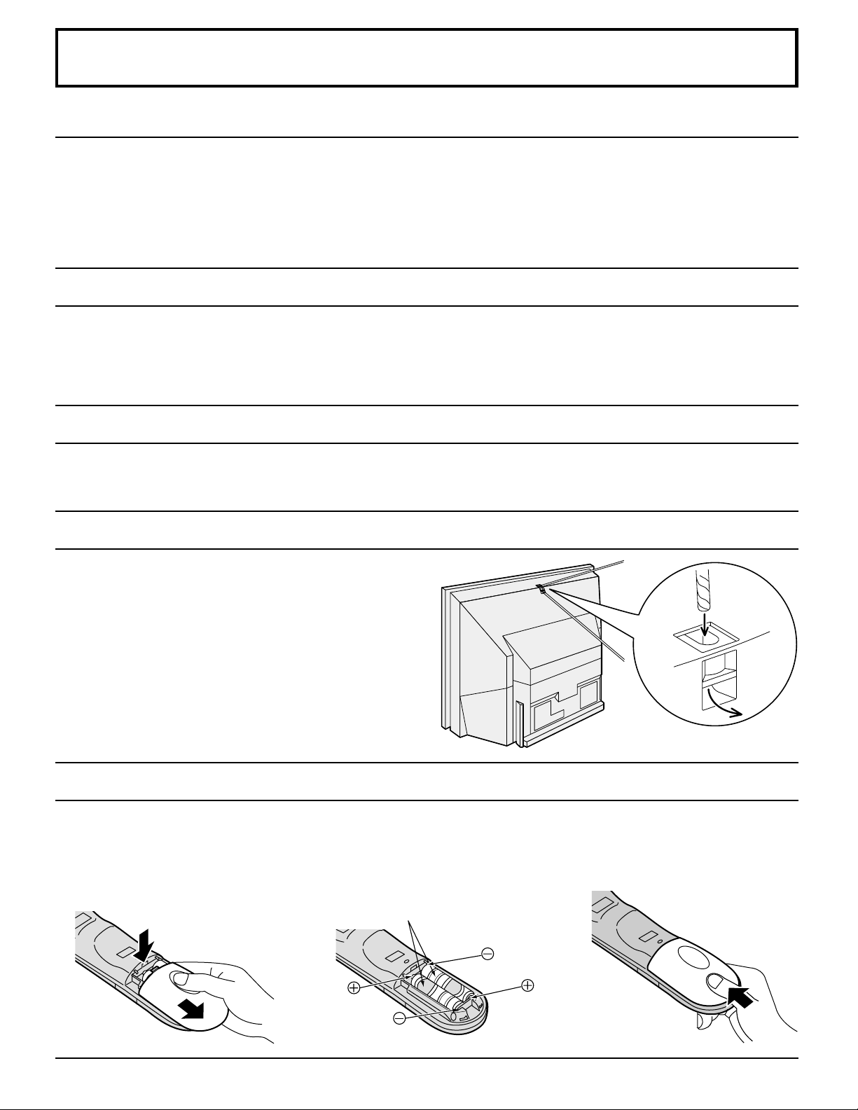
Safety Precaution
Please take safety precautions to prevent the unit from
falling over.
The unit may fall over during earthquakes, or if someone
stands on or shakes the projection TV.
Affixing to a wall
Use a strong rope or a chain (not included) to fasten the
projection TV firmly to a strong support such as a wall or
pillar.
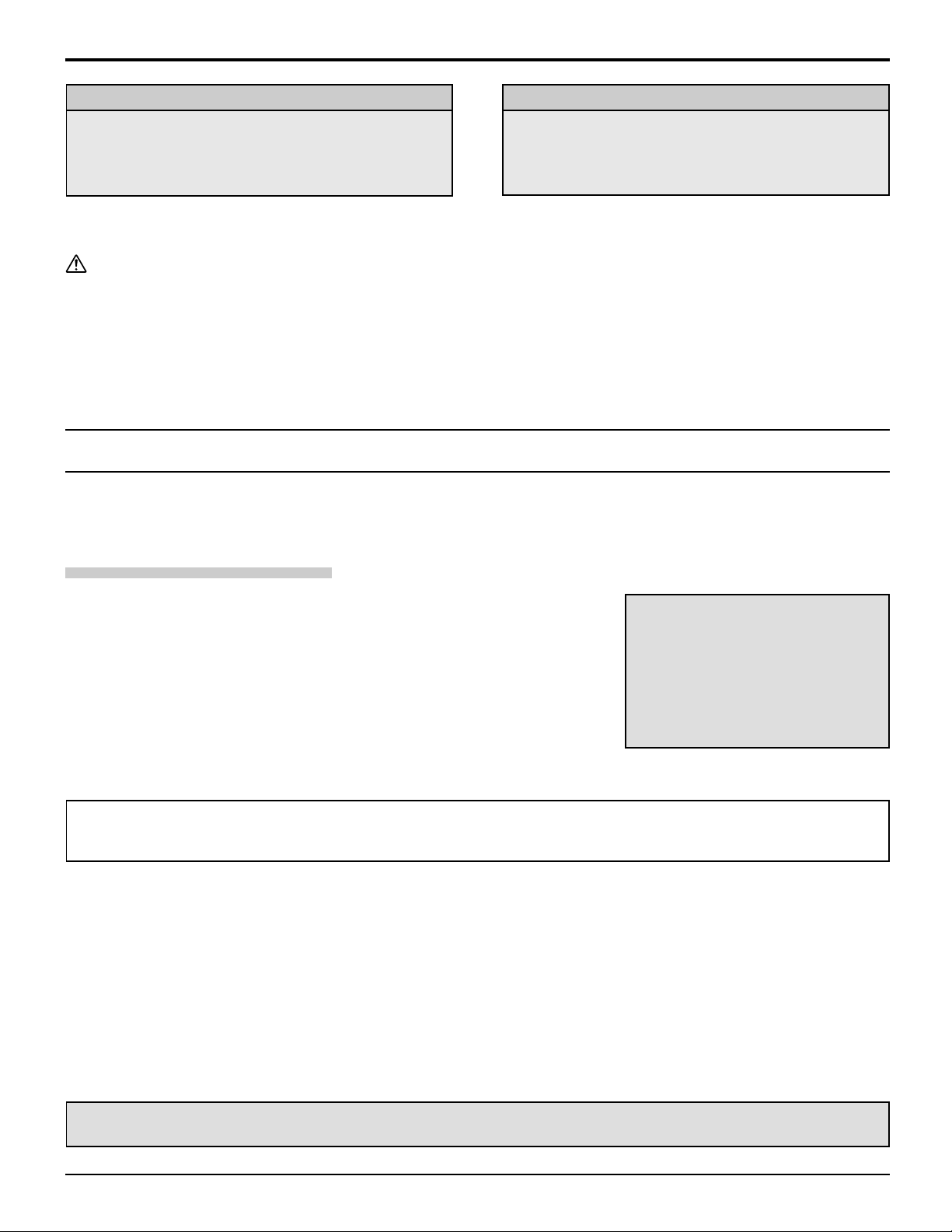
Remote Control Battery Installation
Requires two AA batteries.
1. Turn the Transmitter face down.
Remove top cover by pressing
down on marking and sliding cover
off in the direction indicated.
2. Install the batteries as shown in
the battery compartment. (Polarity
+ or – must match the markings in
the compartment.)
Two AA size
3. Replace the cover and slide in
reverse until the lock snaps.
6
Installation
Helpful Hints:
For frequent remote control users, replace old batteries
with alkaline batteries for longer life.
Helpful Hints:
Whenever you remove the batteries, you may need
to reset the remote control infrared codes. We
recommend that you record the code on page 60, prior
to setting up the remote control.
Precaution on battery use
Incorrect installation can cause battery leakage and corrosion that will damage the remote control transmitter.
Observe the following precautions:
1. Batteries should always be replaced as a pair. Always use new batteries when replacing the old set.
2. Do not combine a used battery with a new one.
3. Do not mix battery types (example: “Zinc Carbon” with “Alkaline”).
4. Do not attempt to charge, short-circuit, disassemble, heat or burn used batteries.
5. Battery replacement is necessary when the remote control acts sporadically or stops operating the projection TV set.
Replacing the lamp unit
The lamp unit is sold separately. To purchase a replacement, call the Panasonic accessory department, toll free at:
1-800-332-5368. (USA only)
Lamp unit Part No. : TY-LA2000
Lamp unit replacement period
The lamp unit for the projection TV should be replaced after approximately 5,000
hours of use in the normal usage mode.
• Warning display after 5,000 hours of use
When the power has been turned on after over 5000 hours of continued use,
LAMP REPLACE will be displayed for approximately 1 min.
A warning message to urge the replacement of the lamp will be displayed in
red at the center of the screen.
Important Points to keep in mind
When replacing the lamp unit with a new one, pay attention to the following points.
Warning:
LAMP REPLACE
• Because the temperature of the lamp unit is elevated immediately after its use, a direct touch to it may cause burns.
Please allow the lamp to cool before handling or replacing the lamp unit.
Cautions for Lamp Unit Replacement:
• Handle the removed old lamp unit carefully. If abusing it, it may have a risk of explosion.
• Wear gloves when replacing the lamp unit.
• If replacing the lamp unit becomes necessary during the operation of the TV, follow the procedure below to turn off the
power and wait until the lamp unit cools completely.
1. Press the POWER button on the remote control unit to turn off the power.
2. Wait for about 90 seconds until the cooling fan stops.
∗ ∗
∗ The lamp cooling fan will continue to operate for about 90 seconds after turning off the power. Do not unplug
∗ ∗
the power cord from the outlet until the fan has stopped. Avoid interrupting the power line such as by using
circuit breakers or switchable power strips.
3. Unplug the power cord from the outlet.
Refer to the instructions enclosed with the lamp unit (part no.: TY-LA2000)
when replacing the lamp.
7
Installation
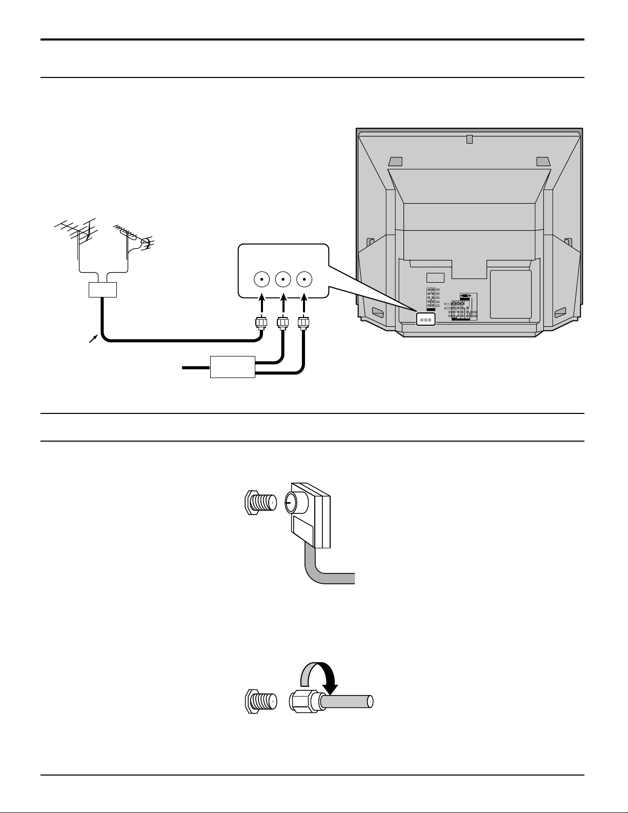
Connecting the Aerial cable to the RF In Terminal
Antenna Connection - For proper reception of VHF / UHF channels, an external antenna is required. For best reception
an outdoor antenna is recommended. Antenna Mode must be set to projection TV.
VHF Antenna UHF Antenna
ANT1 ANT2
SPLIT
OUT
Y
VIDEO
ANT1 ANT2
PB
PR
DIGITAL IN
L
AUDIO
S-VIDEO
R
21
VIDEO
COMPONENT
VIDEO INPUT
L
L
AUDIO
AUDIO
R
SPLIT
OUT
R
213
PROG
INPUT
OUT
Mixer
75 Ohm
Coaxial Cable
Cable Box
Antenna / Cable Connection
Incoming Cable from Home Antenna
VHF / UHF
on Back of Set
Cable Connection - For reception of cable channels (01 - 125) connect the cable supplied by your local cable company.
Antenna Mode must be set to CABLE. (Refer to Antenna Mode section.)
Incoming Cable from Cable Company
VHF / UHF
on Back of Set
Note:
Certain cable systems offset some channels to reduce interference or have Premium (scrambled) channels. A cable
converter box is required for proper reception. Check with your local Cable company for its compatibility requirements.
75 Ohm VHF/UHF on back of TV
8
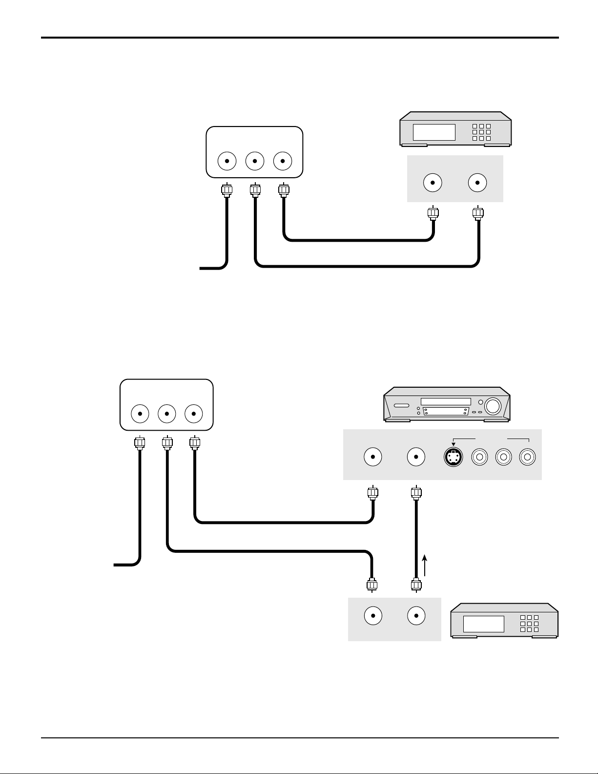
Antenna Connection (Cable Box, no VCR)
Use this configuration when connecting the projection TV to a cable TV system using a Cable Box.
Installation
ANTENNA TERMINALS ON THE
CABLE BOX
BACK OF THE PROJECTION TV
ANT1 ANT2
SPLIT
OUT
TERMINAL ON
ANT OUTPUT
ANT INPUT
THE BACK OF
THE CABLE BOX
Connect the cable from the antenna
or cable system to the ANT1 terminal
on the back of the projection TV.
Incoming Cable from Antenna
or Cable TV System
Antenna Connection (Cable Box, and VCR)
Use this configuration when connecting the projection TV to a cable TV system using a Cable Box and VCR.
ANTENNA TERMINALS ON THE
BACK OF THE PROJECTION TV
ANT1 ANT2
SPLIT
OUT
VCR
OUTPUT
L-AUDIO-R
Connect the cable
from the antenna or
cable system to the
ANT1 terminal on
the back of the
Connect the cable from the
Output terminal on the back
of the Cable Box to the
Antenna input terminal on the
back of the VCR.
ANT OUTPUT
ANT INPUT
S VIDEO VIDEO
projection TV.
Incoming Cable
from Antenna
or Cable TV
Connect the cable from the antenna or cable
system to the Input terminal on the back of
the CABLE BOX.
TO VCR
CABLE BOX
System
TERMINAL ON
THE BACK OF
THE CABLE BOX
ANT INPUT
ANT OUTPUT
Notes:
(1) When the antenna cable is connected to the projection TV antenna terminal via a cable box or VCR, set the TV channel
to CH3 or CH4 cable, after select ANT2 in the PROGRAM CHANNELS. (See page 23) This does not apply when
signal is input from VIDEO INPUT.
(2) To use special features such as Favorite Channel Captions, ANT1 must be selected in the PROGRAM CHANNELS.
(See page 23)
9
Installation
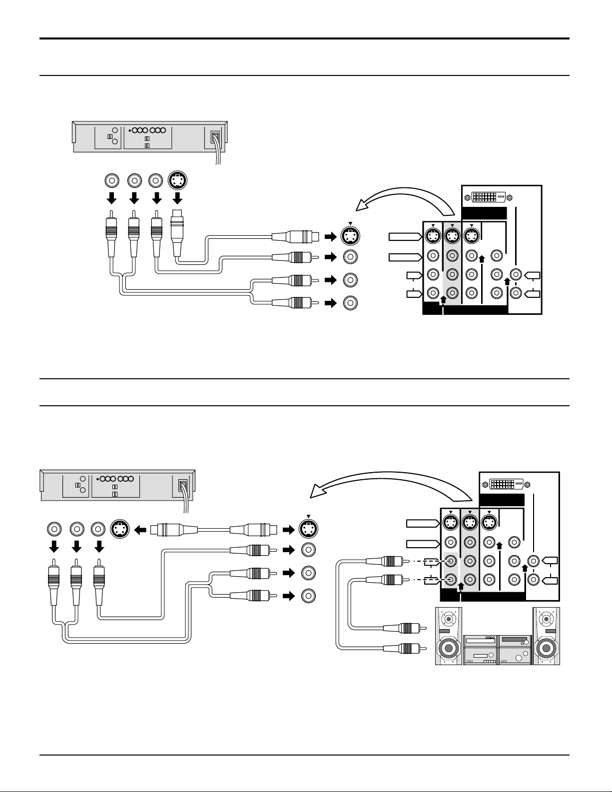
How to connect the “1, 2, 3, 4” Input Terminals
Connects VCRs and other peripheral equipment
(VHS VCR or Super-VHS VCR)
Notes:
Audio
OUT
R L
Video
OUT
S Video
OUT
VIDEO
AUDIO
S VIDEO
VIDEO
AUDIO
DIGITAL IN
L
R
PROG
OUT
213
INPUT
L
AUDIO
R
(1) Similar connections are available at the INPUT 1, 2, 3, 4 input terminals.
Input 4 is located on the front of the unit.
Select the desired VIDEO input position by pushing the TV/VIDEO button. (See page 15)
(2) When connecting video cables, priority is given to the S Video cable when the S Video input terminal and the video
input terminal are connected at the same time.
How to connect the AV Prog. Out Terminals
The “Prog. Out” Terminals output the same signals as the main picture on the projection TV screen and sound from the
speaker at that time, e.g. TV programs or signals from INPUT 1, 2, 3, 4 terminals.
Recording Equipment
(VHS VCR)
Audio
OUT
R
Video
S Video
OUT
L
OUT
S VIDEO
VIDEO
AUDIO
L
R
PROG
OUT
DIGITAL IN
L
AUDIO
R
213
INPUT
VIDEO
AUDIO
Notes:
(1)
Never connect the VIDEO IN and Prog. OUT terminals to the same video recorder , as this could cause incorrect operation.
(2) The monitor output emits the main picture’s normal video and audio signals.
(3) Even if the television is in picture-out-picture condition, Prog. OUT terminals output the same signals as main picture on
the screen and sound from speaker. Sub picture including still, channel search, etc. will not be output at the PROG.
OUT terminals.
(4) Signal (Y, PB, PR) is not output at the Prog. OUT terminals.
(5) To AUDIO AMP terminals cannot be used directly with external speakers.
10
Installation
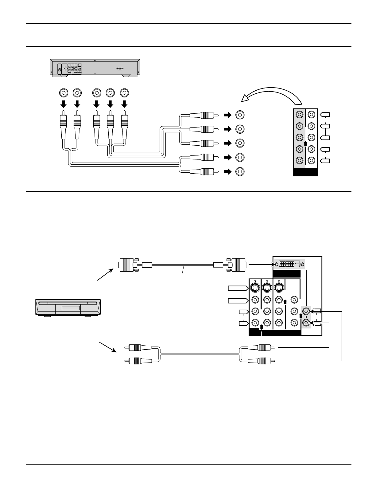
How to connect the COMPONENT VIDEO Input Terminals
(DVD Player)
Note:
Audio
OUT
LR
DVD(
Y-PB-P
R
) OUT
R
P
PBY
Y
VIDEO
P
B
P
R
L
AUDIO
R
21
COMPONENT
VIDEO INPUT
Similar connections are available at the COMPONENT VIDEO Input 1, 2 Terminals.
How to connect the DIGITAL IN Terminals
1. Connecting a DTV Decoder to DIGITAL IN
When connecting a DTV decoder to DIGITAL-IN, be sure not to select “SKIP” or “PC” from the INPUT LABEL menu. Failing
to do so may result in a distorted display or black out (refer to page 36).
DIGITAL IN terminals
DIGITAL IN
DIGITAL IN cable
DTV Decoder
(Supplied)
K1HA24DA0005 (2 m)
S VIDEO
VIDEO
AUDIO
L
R
PROG
OUT
213
INPUT
L
AUDIO
R
Audio
2 × RCA plug
By inputting a High-bandwidth Digital Content Protection high-definition picture source to the DIGITAL IN terminal of this
television, high-definition pictures can be displayed on the screen in their digital form. (This terminal is for use in the future
when High-bandwidth Digital Content Protection DTV decoders, DVD players and D-VHS are put on the market.)
Note:
The DIGIT AL IN terminal can only be used with 1080i, 720p and 480p picture signals. Set the DTV Decode DIGITAL OUT
terminal Output setting to 1080i, 720p or 480p. For detailed information, refer to the DTV decoder instruction manual. If
you cannot display the picture because your DTV decoder does not have a DIGITAL OUT terminal Output setting, use the
component Video Input (or the S Video Input or Video Input). In this case the picture will be displayed as an analog signal.
11
Installation
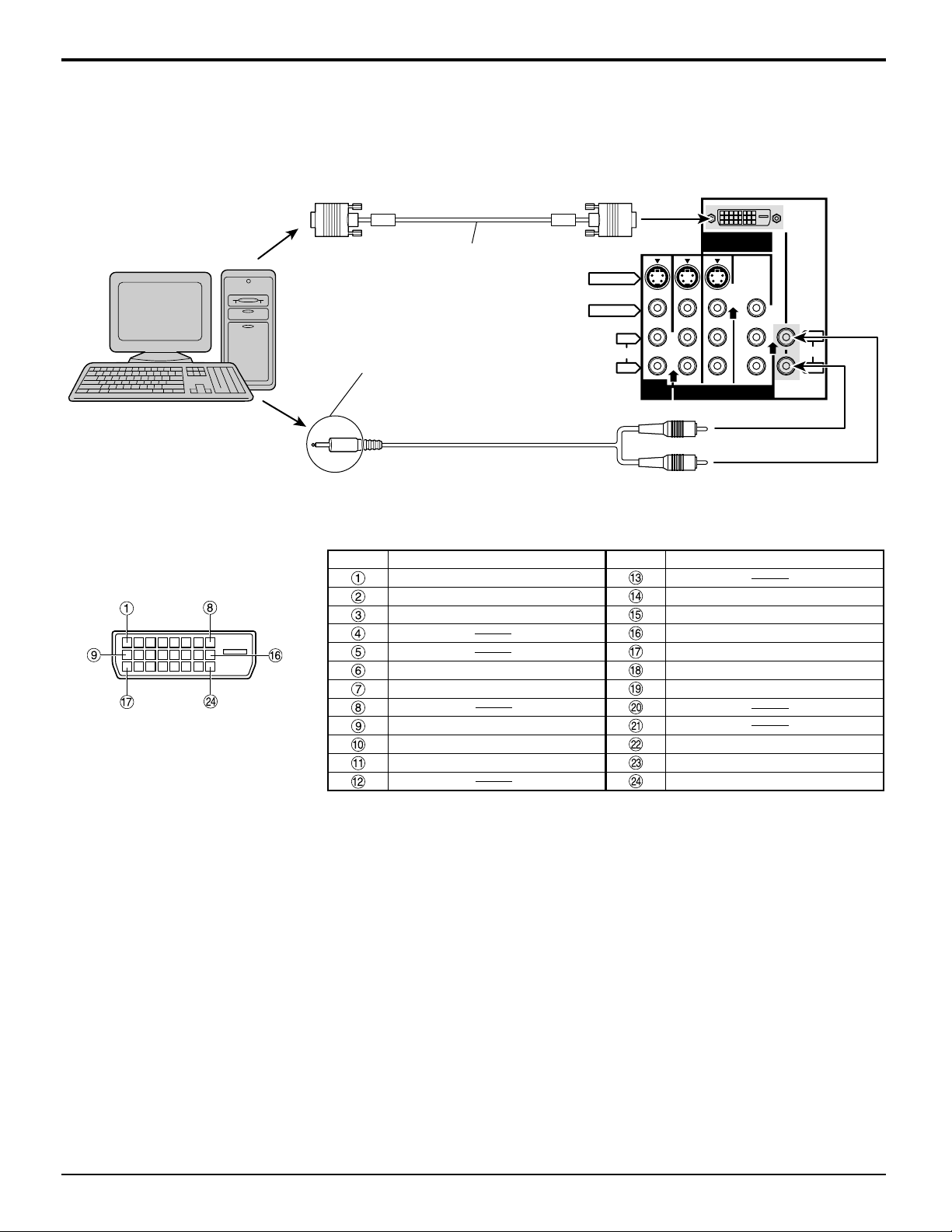
2. Connecting a PC to DIGITAL IN
When connecting a PC to DIGIT AL-IN, be sure to select “PC” from the INPUT LABEL menu. Failing to do so may result in
a distorted display or black out (refer to page 36).
DIGITAL IN terminals
PC with digital
RGB video out
DIGITAL IN cable
(Supplied)
K1HA24DA0005 (2 m)
Connect a cable that matches
the audio output terminal on the
S VIDEO
VIDEO
AUDIO
L
R
PROG
OUT
DIGITAL IN
L
AUDIO
R
213
INPUT
computer.
Audio
Note:
2 × RCA plug
If your PC does not support the Plug-and-Play capability (DDC1/2B) for displays, it will require reconfiguration after the
display is connected to the PC.
Digital RGB Input Connector
Pin Layouts
Pin No.
Signal Name
T.M.D.S. data 2T.M.D.S. data 2+
T.M.D.S. data 2 shielded
Pin No.
+5 V DC
Ground
Signal Name
Hot plug sense
T.M.D.S. data 0DDC clock
DDC data
T.M.D.S. data 0+
T.M.D.S. data 0 shielded
Connection port view
T.M.D.S. data 1T.M.D.S. data 1+
T.M.D.S. data 1 shielded
T.M.D.S. clock shield
T.M.D.S. clock+
T.M.D.S. clock-
12
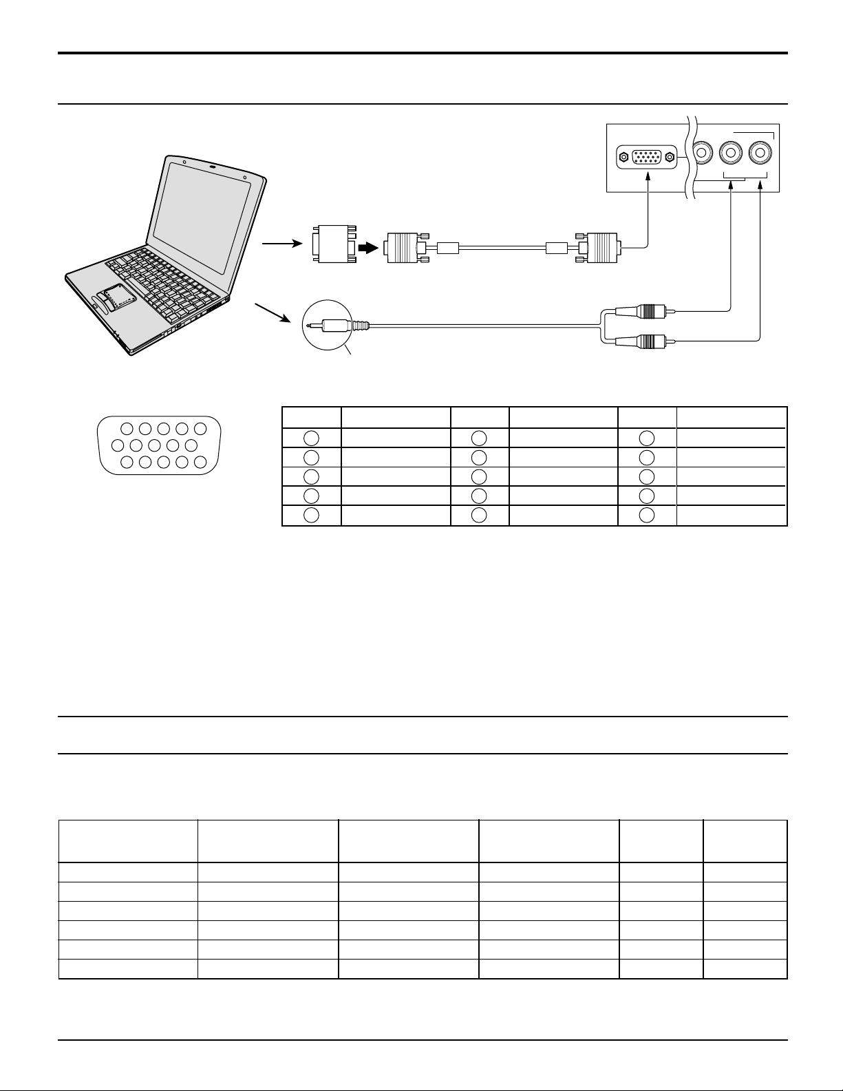
How to connect the PC Input Terminals
1
67839
45
10
15 14 13 12 11
2
Installation
COMPUTER
Conversion adapter (if necessary)
RGB
PC cable
(supplied)
K1HA30DA0003 (2 m)
Audio
Connect a cable that matches
the audio output terminal on the computer.
Signal Names for D-SUB 15P Connector
Pin No.
1
2
Pin Layout for PC Input
Terminal
Notes:
(1) The PC input terminals are DDC1/2B-compatible. If the computer being connected is not DDC1/2B-compatible, you will
need to make setting changes to the computer at the time of connection.
(2) Some PC models cannot be connected to the set.
(3) There is no need to use an adapter for computers with PC / AT compatible D-SUB 15P terminal.
(4) The computer shown in the illustration is for example purposes only.
(5) Additional equipment and cables shown are not supplied with this set.
(6) The picture will become dark if a PC signal with a vertical scanning frequency of 62 Hz is input. To obtain the optimum
picture quality with the projection TV, a vertical scanning frequency of 60 Hz is recommended.
(7) Do not set the horizontal and vertical scanning frequencies for PC signals which are above or below the specified
frequency range.
3
4
5
Signal Name
R
G
B
GND (Ground)
GND (Ground)
Pin No.
6
7
8
9
10
Signal Name
GND (Ground)
GND (Ground)
GND (Ground)
NC (not connected)
GND (Ground)
D-SUB 15P
PC INPUT
2 × RCA plug
Pin No.
11
12
13
14
15
INPUT 4
VIDEO
L-AUDIO-R
Signal Name
GND (Ground)
SDA
HD / SYNC
VD
SCL
Digital and analog RGB signals that can be input
The table below lists the different types of digital and analog RGB signals that can be input.
If a signal which differs greatly from any of the types listed below is input, the picture
image may not be displayed correctly, or a black background may displayed.
Display mode name No. of dots (H
Note:
The number of dots for this set is 800 × 600 for NORMAL display. Number of dots other than 800 × 600 in the above data,
will be converted to 800 × 600 (with the exception of MAC 16, which will be displayed in 832 × 624 dots).
Horizontal scanning Vertical scanning DIGITAL PC INPUT
××
× V)
××
VGA400 640 × 400 31.5 70.1
VGA480 640 × 480 31.5 59.9
SVGA 800 × 600 37.9 60.3
XGA 1024 × 768 48.4 60.0
MAC16 832 × 624 49.7 74.6
720p 1280 × 720 45.0 60.0
frequency (kHz) frequency (Hz) IN (Analog)
Mark:
∗
Input signal can be displayed.
∗∗
∗∗
∗∗
∗∗
∗
∗
13
Location of Controls
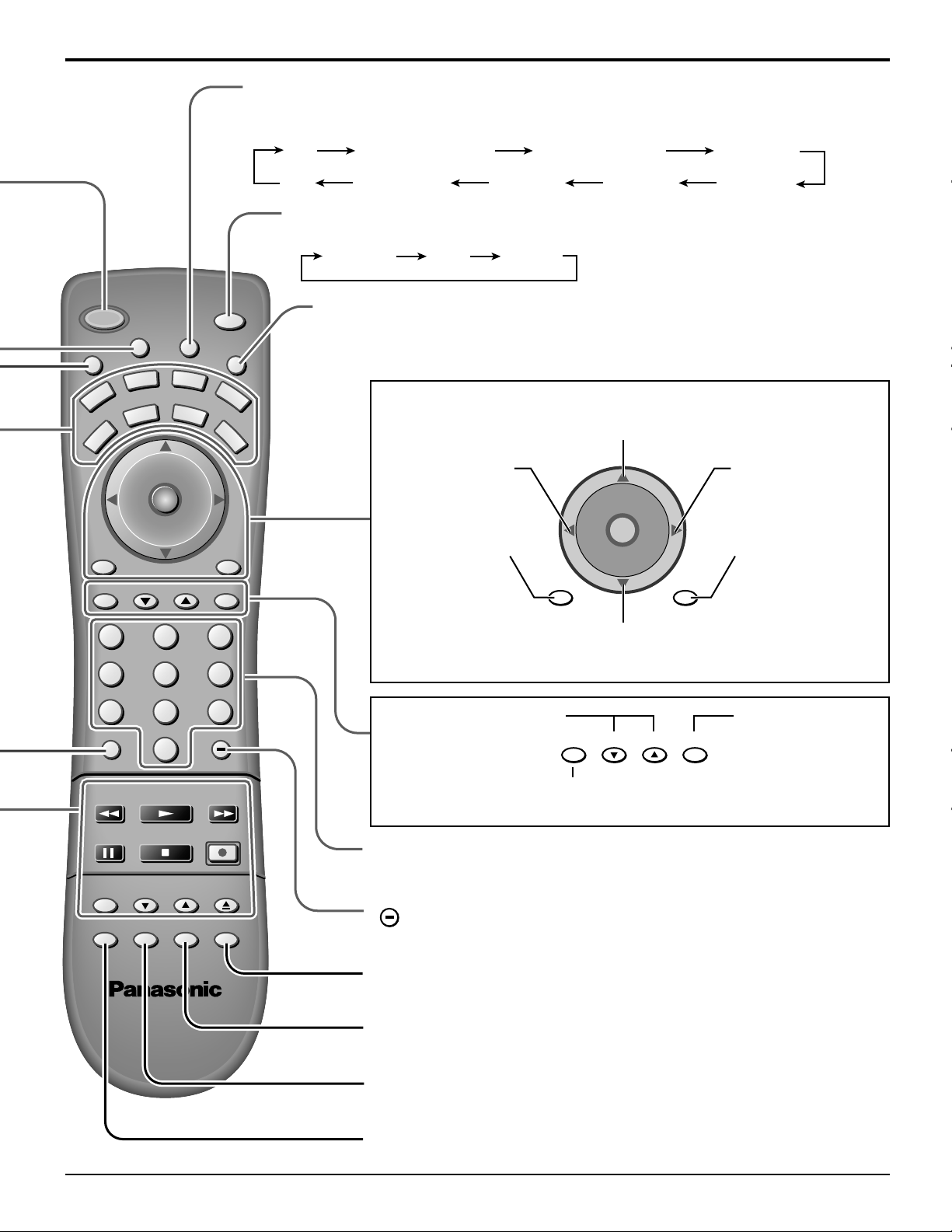
Illuminated Remote Control
Power button
Press to turn the TV ON or OFF (See page 18, 19).
Note: The TV’s power cord must first be plugged into the wall outlet
and then turned on at the POWER switch (standby mode).
ASPECT button
Change of screen size (See page 44).
MUTE button
Press this button to mute the sound, press again to cancel the mute.
Mode Selection buttons
Selects the operation mode for the remote control. (See page 58)
Digital Video Disk Mode Selection for Remote Control
VCR Mode Selection for Remote Control
TV Mode Selection for Remote Control
DVD
VCR
DTV
TV
AUX
CBL
Digital TV Mode Selection for Remote Control
R-TUNE
R-TUNE button
Switches to previously viewed channel or video mode.
4 : 3
ZOOM1 ZOOM2 FULLJUST
Aux Mode Selection for Remote Control
RCVR
Receiver/Amplifier Mode Selection
for Remote Control
DBS
Digital Broadcasting Satellite for
Remote Control
Cable TV Mode Selection for Remote Control
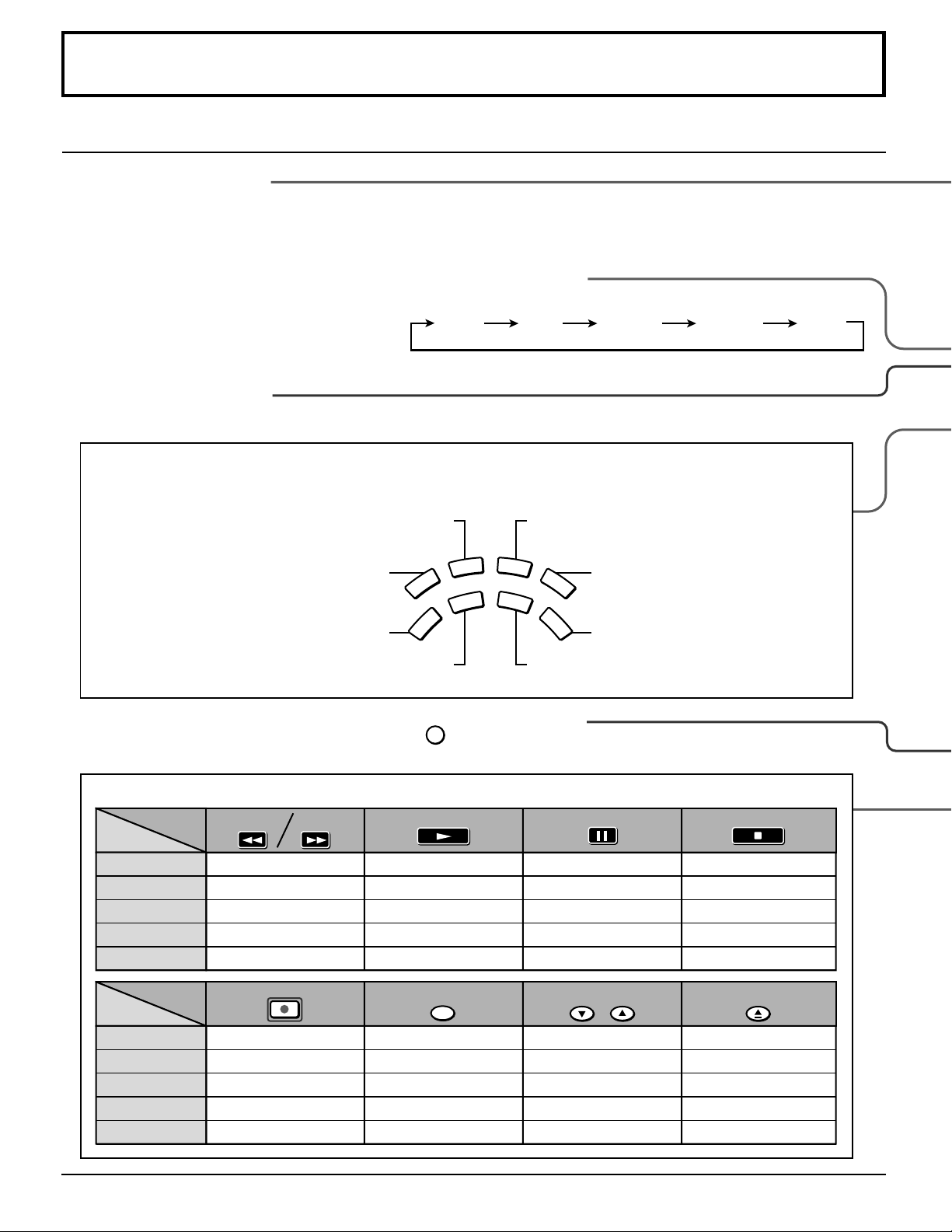
Operation of other Device
ButtonsButtons
Device
TV
VCR
CABLE/DBS
DVD/LD/CD
RCVR
ButtonsButtons
Device
TV
VCR
CABLE/DBS
DVD/LD/CD
RCVR
14
PIP MIN
REW
PIP MAX
FF
PIP Minimize/Maximize
VCR REW/FF
-
Skip Search REW/FF
Surround -/+
REC
VCR RECORD
DBS RECORD
-
-
PLAY
-
PLAY
-
PLAY
-
FREEZE
TV/VCR
PIP or SPLIT FREZE
TV/VCR Switch
TV/DBS Switch
-
-
PAUSE
-
Pause
-
Pause
-
PIP CH
VCR CH
PIP or SPLIT CH up/down
VCR CH up/down
TV/DBS CH up/down
-
-
STOP
-
STOP
-
STOP
-
SEARCH
OPEN/CLOSE
PIP Search
-
-
OPEN/CLOSE
-
TV/VIDEO button
The input mode changes each time this button is pressed.
[Example]
TV
COMPONENT 1
COMPONENT 2
Location of Controls
VIDEO 1
U
M
POWER
E
T
VCR
TV
BBE
MENU
A
VOL VOL
S
P
DVD
DTV
T
V
T
/
V
C
E
I
D
AUX
CBL
CH
O
I
T
N
C
A
CH
PAGEEXIT
123
456
SAP
E
O
RCVR
DBS
RECALL
GUIDE
VIDEO 3VIDEO 4DIGITAL-INPC
VIDEO 2
SAP button
Selects Audio mode (See page 37).
STEREO SAP MONO
Lights the remote control buttons.
Press to illuminate remote buttons.
L
I
G
H
T
Changes to the next channel up
Moves cursor upward during menu mode.
Reduces volume
Moves cursor to the
left during menu
mode.
Displays menu
Press to access
DTV, DBS or DVD
menus.
VOL VOL
BBE
MENU
CH
O
I
T
N
C
A
CH
RECALL
Increases volume
Moves cursor to
the right during
menu mode.
Press to display
time, channel,
sleep timer and
other options.
During TV mode press
to select BBE ON or
BBE OFF.
Changes to the next channel down
Moves cursor downward during menu mode.
7809
R-TUNE PROG
PIP MIN
REW
FREEZE
TV/VCR
PIP SPLIT MOVE SWAP
PLAY
STOPPAUSE
PIP CH
VCR CH
PIP MAX
REC
SEARCH
OPEN/CLOSE
Page up/down for DBS,
skip +/- for DVD & CD.
FF
Returns to normal viewing from the MENU screen.
Previous item in MENU.
GUIDEPAGEEXIT
GUIDE button
for DBS.
Direct program number
selection buttons
PROG
PROG dash button
Program dash channel numbers for DTV and DBS.
Swap pictures in Split Screen and Picture in Picture operation
(See page 40, 43).
Move PIP frame in Picture in Picture Operation (See page 41).
Split Screen (see page 42)
Picture in Picture Operation (see page 40)
15
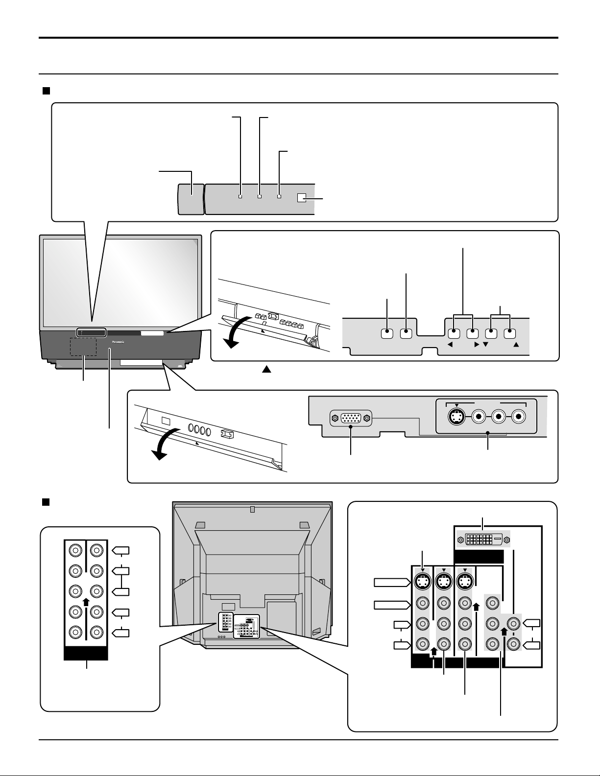
Location of Controls
Controls and Terminals on the Projection TV
FRONT
POWER SWITCH
(see page 18)
TM
DLP
A TEXAS INSTRUMENTS TECHNOLOGY
Lamp unit
(see page 7)
POWER INDICATOR
G-POWER ON
(see page 18, 19)
POWER
HD
TV
COMPATIBLE 1080 i / 720p
Press the
front cover to open.
G-POWER ON
Open
LAMP
This indicator lights up when there is a malfunction with the
lamp unit (see page 7, 65)
TEMP
This indicator lights up when there is an abnormal
temperature in the unit (see page 65)
LAMP TEMP
Remote Control Sensor (see page 18, 19)
Volume up(+) / down(–) buttons (see page 15, 17)
Input mode selection buttons (see page 15)
Action button (Press to
make selections.)
mark on the center of the
PC INPUT
TV/VIDEOACTION
Channel up / down
buttons
(see page 15, 17)
VOLUME
INPUT 4
CHANNEL
Speaker panel
REAR
Y
VIDEO
P
P
L
AUDIO
R
21
COMPONENT
VIDEO INPUT
Component signal input
(see page 11)
VIDEO
L-AUDIO-R
Open
PC Input terminal
S-VIDEO
Input4 terminals
Video camera and TV game
cable terminal
DIGITAL IN Terminals (see page 11, 12)
Prog out terminals
(see page 10)
B
R
Y
VIDEO
P
B
P
R
DIGITAL IN
L
AUDIO
S-VIDEO
R
21
VIDEO
COMPONENT
VIDEO INPUT
ANT1 ANT2SPLIT
OUT
L
L
AUDIO
AUDIO
R
R
213
PROG
INPUT
OUT
S VIDEO
VIDEO
AUDIO
L
R
PROG
OUT
DIGITAL IN
L
AUDIO
R
213
INPUT
Input1 terminals
(see page 10)
Input2 terminals (see page 10)
16
Input3 terminals (see page 10)
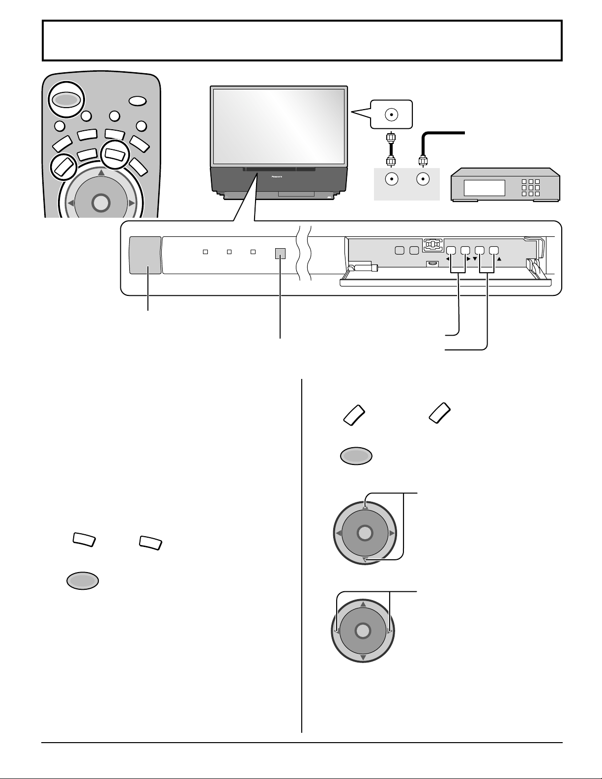
Cable TV / VHF, UHF and CATV
ANTENNA TERMINAL ON THE
BACK OF THE PROJECTION TV
OUTPUT
from the TV set.
Volume adjusters
•
Channel selectors
•
M
POWER
E
T
U
VCR
TV
T
V
T
/
V
C
E
P
S
A
AUX
DVD
CBL
DTV
CH
O
I
T
N
C
A
VOL VOL
SAP
I
D
E
O
L
I
G
H
T
RCVR
DBS
Power switch
POWER
G-POWER ON
TM
DLP
A TEXAS INSTRUMENTS TECHNOLOGY
LAMP TEMP
Remote control sensor
HD
TV
COMPATIBLE 1080 i / 720p
Operation can be done
T o Antenna
INPUT
TV/VIDEOACTION
Input
Incoming Cable from
Antenna or Cable TV
System.
CABLE BOX
VOLUME
CHANNEL
Cable TV
When the antenna cable is connected to the TV antenna
terminal via a cable box or VCR, set the TV channel to CH3
or CH4.
This does not apply when signal is input from VIDEO
INPUT.
Confirming
Confirm that registration with cable TV provider and
connection of equipment are completed. Turn the CABLE
BOX on and select the desired volume level.
1
2
CBL
POWER
Press
Press while pointing the remote control
towards the CABLE BOX.
Note:
The remote control code number is set for
Panasonic products.
When peripheral equipment does not
operate, reset code (See page 58 - 59).
Operate the CABLE BOX and select the desired
3
volume level.
CBL
to confirm.
VHF, UHF and CATV
1
TV
Press
the remote control.
2
POWER
Press to turn the TV on (See page 18,
19).
3
CH
O
I
T
N
C
A
VOL VOL
CH
4
CH
O
I
T
N
C
A
VOL VOL
CH
Notes:
(1) The channel number and volume level remain the same
even after the TV is turned off.
(2) Power consumption and howls can be reduced if the
volume level is lowered.
to operate the TV set with
TV
Press to select the desired
channel.
Select the desired volume level.
17
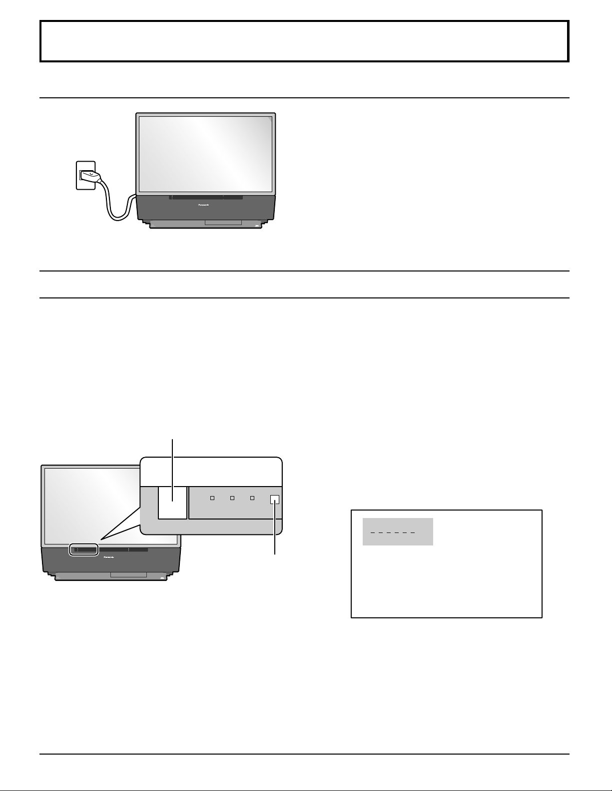
Power ON / OFF
LAMP TEMP
G-POWER ON
POWER
Connecting the Plug to the Wall Outlet
The projection TV must first be switched on at the wall
outlet.
The projection TV will become standby mode.
TM
DLP
A TEXAS INSTRUMENTS TECHNOLOGY
Turning the Power ON and OFF
Always be sure to follow the procedure given below to turn the projection TV power ON and OFF.
The lamp cooling fan will continue to operate for approximately 90 seconds after the power is turned off by the remote control.
•
After the cooling fan has stopped, the power indicator will not illuminate (Stand-by).
If you wish to turn the power ON while the cooling fan is operating, press the power button on the remote controller. The
power indicator on the TV will then flash in green, and the projection TV will turn ON as soon as the cooling fan stops.
In normal circumstances, use the remote control to turn the power OFF (turning the picture OFF).
Do not disconnect the power cord from the power outlet and do not open any circuit breakers while the cooling
fan is still operating.
HD
TV
COMPATIBLE 1080 i / 720p
Power switch
Push the Power switch on the projection TV to turn the power
on.
Push the Power switch on the projection TV to turn the set off.
CH 3
SAP
JUST
Remote control sensor
TM
DLP
A TEXAS INSTRUMENTS TECHNOLOGY
HD
TV
COMPATIBLE 1080 i / 720p
VIVID
Example: The screen above is displayed for a while after the
projection TV is turned on. (Setting condition is an
example.)
18
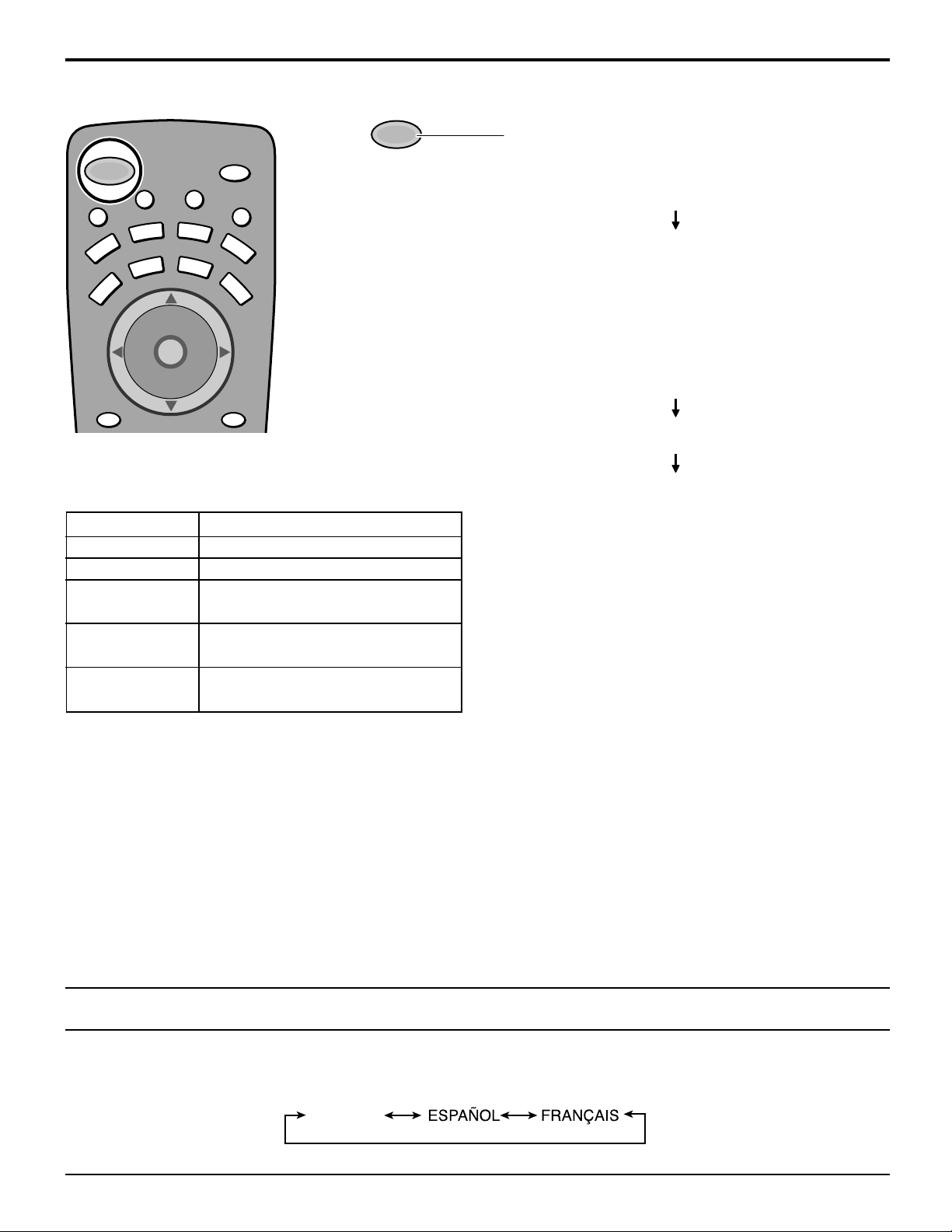
Power (ON/Off) button
Power ON / OFF
V
/
AUX
CBL
N
V
I
D
E
SAP
O
RCVR
DBS
RECALL
U
M
POWER
E
T
VCR
TV
BBE
MENU
T
T
C
E
P
S
A
DVD
DTV
CH
O
I
T
C
A
VOL VOL
CH
The Power Indicator
LED
Not illuminated
Green
Green blink
(approximately 10 seconds after)
Orange
Orange blink
Power – OFF (Blanking mode)
(approximately 10 seconds after)
Power – OFF (Cooling mode)
(approximately 90 seconds after)
POWER
Push the Power button to turn the projection TV ON,
from Stand-by mode.
L
I
G
H
T
The Power Indicator will blink Green.
Approximately 10 seconds
The Power Indicator will become Green.
Push the Power button to turn the projection TV to
Stand-by mode.
The Power Indicator will become Orange.
Approximately 10 seconds
The Power Indicator will blink Orange.
Approximately 90 seconds.
The power Indicator light will go out.
ACTION
Stand – by
Power – ON
Power – ON
Note:
The TV will still consume some power as long as the
power cord is still inserted into the wall outlet.
Menu Language Selection
In SET UP Menu, Select IDIOMA/LANGUE to change menu language to ENGLISH, ESPAÑOL (Spanish) or FRANÇAIS
(French). (refer to page 22)
ENGLISH
19
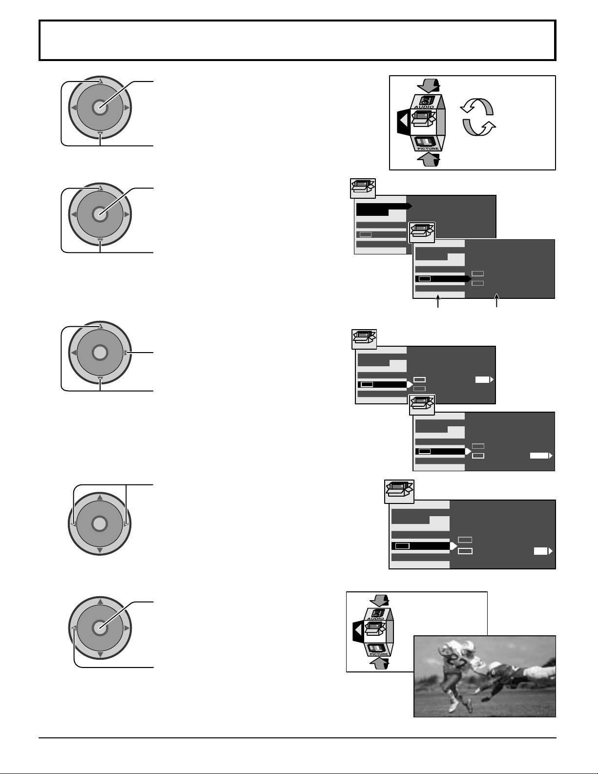
Roller Guide Menu Navigation
1
2
3
CH
O
I
T
N
C
A
VOL VOL
CH
CH
O
I
T
N
C
A
VOL VOL
CH
CH
O
I
T
N
C
A
VOL VOL
CH
Press to display the roller guide menu.
Press to rotate to desired icon.
Press to display the main menu and
submenu field.
Press to select main menu feature.
Press to enter submenu field.
Press to select desired submenu feature.
SET UP
IDIOMA /
LANGUE
PROG CHAN
CC
OTHER ADJ.
SET UP
IDIOMA /
LANGUE
PROG CHAN
CC
OTHER ADJ.
EXIT
SET UP
MODE
SET UP
IDIOMA /
LANGUE
PROG CHAN
CC
OTHER ADJ.
CC
ON MUTE NO
CC
MODE
ENGLISH
CC
CC
OFF
ON MUTE
MODE
Submenu fieldMain menu field
NO
OFF
4
5
CH
O
I
T
N
C
A
VOL VOL
CH
CH
O
I
T
N
C
A
VOL VOL
CH
Press to select or adjust.
Press twice to return to the roller guide.
Press to exit roller guide.
This returns the set to the normal viewing.
EXIT
SET UP
SET UP
IDIOMA /
LANGUE
PROG CHAN
OTHER ADJ.
SET UP
IDIOMA /
LANGUE
PROG CHAN
CC
OTHER ADJ.
CC
CC
CC
ON MUTE
CC
MODE
ON MUTE
MODE
CC
NO
OFF
NO
C1
20
NORMAL PICTURE
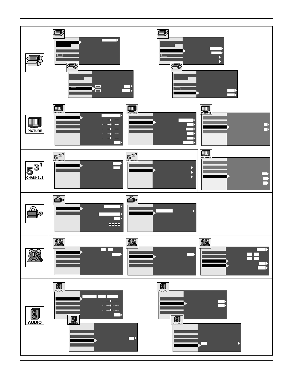
Roller Guide Menu Navigation
SET UP
SET UP
IDIOMA /
LANGUE
PROG CHAN
CC
OTHER ADJ.
SET UP
VIDEO ADJ.
OTHER ADJ.
POS ADJ.
PC ADJ.
FAVORITES
CAPTION
MODE
IDIOMA /
LANGUE
PROG CHAN
CC
OTHER ADJ.
PIC MODE
COLOR
TINT
BRIGHTNESS
PICTURE
SHARPNESS
NORMAL
CHANNEL SCAN
ENTER CHANNEL
FAVORITE CHANNELS
2 5 8 10
15 18 25
ENGLISH
CC
ON MUTE NO
CC
MODE
STANDARD
NO
FAV
SET UP
IDIOMA /
LANGUE
PROG CHAN
CC
OTHER ADJ.
OFF
VIDEO ADJ.
OTHER ADJ.
POS ADJ.
PC ADJ.
COLOR TEMP
BLACK EXT.
VIDEO NR
3D Y / C FILTER
COLOR MATRIX
FREEZE
15
FAVORITES
CAPTION
PRESET CAPTION
MANUAL CAPTION
SET UP
IDIOMA /
LANGUE
PROG CHAN
CC
OTHER ADJ.
NORMAL
SPLIT
MODE
ANTENNA
AUTO PROGRAM
MANUAL PROGRAM
ON
OFF
ON
SD
INPUT LABEL
CABLE
ANT1
AUTO POWER ON
CHAN BANNER
VIDEO ADJ.
OTHER ADJ.
POS ADJ.
PC ADJ.
VIDEO ADJ.
OTHER ADJ.
POS ADJ.
PC ADJ.
OFF
OFF
V-POSITION
H-POSITION
CLOCK PHASE
DOT CLOCK
SIZE
0
0
16
0
2
LOCK
TIMER
LOCK
MODE
HOW LONG ?
TIMER
CLOCK SET
SLEEP
TIMER1
TIMER2
AUDIO ADJ.
OTHER ADJ.
SURROUND
SPEAKERS
LOCK SET
BLOCK PROGRAMS :
STATUS
CHANGE CODE
TIME AM
DAY
MODE
STEREO SAP MONO
BASS
TREBLE
BALANCE
NORMAL
AUDIO ADJ.
OTHER ADJ.
SURROUND
SPEAKERS
CHANNEL
U.S. MOVIES
12 00:
MODE
ON
SUN
NO
LOCK
MODE
HOW LONG ?
TIMER
CLOCK SET
SLEEP
TIMER1
TIMER2
ON
12HOURS
HOW LONG ?
AUDIO ADJ.
OTHER ADJ.
SURROUND
SPEAKERS
30
AI SOUND
BBE
AUDIO ADJ.
OTHER ADJ.
SURROUND
SPEAKERS
TIMER
CLOCK SET
SLEEP
TIMER1
TIMER2
ON
DAY
ON TIME
OFF TIME
ENTER CHANNEL
SET
ON
ON
12 00:
13 00:
Daily
PM
PM
5
YES
21
 Loading...