

Panasonic PT-52DL10 Service Manual

ITD0012019C1
DLP™ Technology-Based Projection TV
PT-52DL10
LR1 chassis
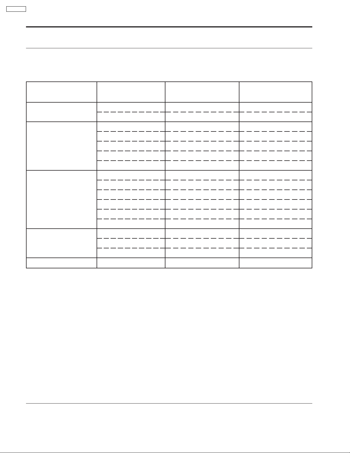
Specification
Power Source:
Power Consumption:
Display:
Screen Size:
DMD™ element:
Sound:
Speaker
Audio Output
HID Lamp:
Channel Capability-181:
Accessories Supplied:
Input signals:
AC 120 V, 60Hz
Average use: Maximum Current 3.8 A
Stand-by condition: 0.74 W (when cooling fan is stopped)
52-inch, 16 : 9 aspect ratio
45.31 " (1151 mm) (W) × 25.49 " (647.5 mm) (H) × 52 " (1321 mm) (diagonal)
Element size : 0.8 inches (aspect ratio; 16 : 9)
Display method : 1 DMD™ element, DLP system
Pixels : 1280 dots × 720 lines
4 Speakers
20 W [10 W + 10 W] (10 % THD)
200 W HID (High Intensity Dischange) Lamp (recommended replacement period approximately 5000
hours)
VHF-12 : UHF-56 : Cable-125
Remote control Transmitter EUR511162
R6 (AA) Battery × 2
RGB cable : TSXF147
RGB input D-SUB 15pin
AV INPUT 1-4 VIDEO 1.0 Vp-p (75!)
(RCA Pin Jack Type)
S-VIDEO Y : 1 Vp-p (75!), C : 0.286 Vp-p (75!)
(not supplied for AV INPUT 3)
(Mini DIN 4pin)
AUDIO L-R 0.5 Vrms
(RCA Pin Jack Type × 2)
TO AUDIO AMP AUDIO L-R 0.5 Vrms
(RCA Pin Jack Type × 2)
© 2000 Matsushita Electric Industrial Co., Ltd. All
rights reserved. Unauthorized copying and
distribution is a violation of law.
PT-52DL10
COMPONENT VIDEO Y 1.0 Vp-p (including synchronization)
INPUT 1-3 PB/P
Output signals: AV PROG. OUT VIDEO 1.0 Vp-p (75!)
Dimensions (W×D×H): 47.7 " (1211 mm) × 177.7 " (450 mm) × 39.2 " (995 mm)
Weight (Mass): 130 lbs. (59 kg) Net
R
AUDIO L-R 0.5 Vrms
(RCA Pin Jack Type × 2)
(RCA Pin Jack TYPE)
S-VIDEO Y : 1 Vp-p (75!), C : 0.286 Vp-p (75!)
(Mini DIN 4pin)
AUDIO L-R 0.5 Vrms
(RCA Pin Jack Type × 2)
±0.35 Vp-p
Note:
Design and Specifications are subject to change without notice. Weigh t and Dimensions shown are approximate.
Trademark Acknowledgements:
"""" ·"""" DLP and DMD are registered trademarks of the Texas Instruments.
"""" ·"""" VGA and XGA are trademarks of International Business Machines Corporation.
"""" ·"""" S-VGA is a registered trademark of the Video Electronics Standards Association.
All other trademarks are the property of the various trademark owners.
CONTENTS
Page Page
1 Safety Precautions 5
1.1. General Guidelines
1.2. Leakage Current Cold Check
1.3. Leakage Current Hot Check (See Fig.1)
1.4. Hot-Check Circuit
1.5. Lamp Precautions
2 Functions for Safety
2.1. Temperature Detection for the Lamp Unit
2.2. Interlock Switch
3 Customer Operation
4 New functions on this projector
4.1. DLP™ Projector
4.2. DMD™ element structure
4.3. DMD™ element operation
5 Chassis Board Layout
6 Location of Lead Wiring
17
17
17
18
19
20
6.1. Location of Lead Wiring (DG)
5
5
5
5
5
6
6
6
7
6.2. Location of Lead Wiring (Rear)
7 Disassemble for Service
7.1. View of Front/ Rear of the Cabinet, Optical Block/ Chassis
Block
7.2. Removal of Rear Cover and Shield Plate
7.3. Removal of Chassis Block
7.4. Removal of Front Decorative Speaker Grille
7.5. Removal of Projection Screen Unit
7.6. Projection Screen Assembly
7.7. Service Position for Optical Block
7.8. Removal of Control Panel
7.9. Removal of Optical Block
7.10. Removal of FMT (Formatter) Board
7.11. Removal of DG Board
7.12. Removal of Ballast Board
2
20
21
22
22
23
24
25
26
27
28
29
30
31
33
35

8 Service Position for Chassis Block 36
9 Self-check Function
38
9.1. Self-check of the microcomputer control system (bus line)
9.2. Self check for the power supply
10 Serviceman Mode
10.1. Entry into service adjustment mode
10.2. Concurrent Mode
10.3. How to Read the Serve Adjustment Mode
10.4. Concurrent Mode Function
10.5. FMT ADJUST
10.6. TEST PATTERNS
10.7. DG ADJUST
10.8. TU ADJUST
11 Adjustment
11.1. AFT adjustment
11.2. Multisound adjustment [Input level adjustment]
11.3. Multisound adjustment [Stereo separation adjustment ]
11.4. LED check
11.5. Screen Rotation
11.6. Screen Centering
11.7. Lens focus adjustment
11.8. DG-PCB signal level adjustment
11.9. CW index delay adjustment
11.10. White balance adjustment
11.11. On-screen phase adjustment
12 Firmware Upgrade
12.1. TU-MPU by TV loader
12.2. DG-MPU by MBFLASH
12.3. FPGA2 by MaxPlus2
13 After replacing the ICs on DG Board
13.1. IC9706 (DG-MPU)
13.2. IC9027 (FPGA2)
13.3. IC9313 (FPGA1)
13.4. IC9705 (EEPROM)
13.5. IC9707 (EEPROM)
13.6. IC9709 (EEPROM)
14 Trouble shooting
14.1. General
14.2. Front LED check
14.3. DG LED analysis
14.4. Visual Check
14.5. DG examination
14.6. DG defect analysis
14.7. FE analysis
14.8. Sound analysis
15 Test Points in DG Board
15.1. Location of Test Points
15.2. Front View with Test Points
15.3. Wave Forms of Test Points
15.4. Each LSI Check
15.5. Circuit Confirming Hint
15.6. LSI Voltage Source Points (Front)
15.7. LSI Voltage Source Points (Rear)
38
39
41
41
41
42
43
43
44
44
44
49
49
49
49
50
51
52
53
53
54
54
55
56
56
57
59
60
60
60
60
60
60
60
61
61
62
63
65
66
67
68
69
70
71
72
73
74
75
76
77
15.8. Clock & Sync Reference Flow
16 Condutor Views
16.1. A-Board
16.2. PA-Board
16.3. PB and PL-Board
16.4. H-Board
16.5. Z and CC-Board
16.6. V, K and G-Board
16.7. DG-Board
16.8. U-Board
17 Block Diagram
17.1. Overall Block Diagram
17.2. Power Block Diagram
17.3. Control Block Diagram
17.4. Video Block Diagram
17.5. DG Block Diagram
17.6. Audio Block Diagram
17.7. U-Board Block Diagram
17.8. Interconnection Block Diagram
18 Schematic Diagrams
18.1. Schematic Diagram Notes
18.2. PL and PA-Board (1/2) Schematic Diagram
18.3. PA-Board (2/2) Schematic Diagram
18.4. PB-Board Schematic Diagram
18.5. A-Board (1/4) Schematic Diagram
18.6. A-Board (2/4) Schematic Diagram
18.7. A-Board (3/4) Schematic Diagram
18.8. A-Board (4/4) Schematic Diagram
18.9. CC-Board Schematic Diagram
18.10. G, K and V-Board Schem atic Diagram
18.11. H-Boa rd (1/3) Schematic Diagram
18.12. H-Boa rd (2/3) Schematic Diagram
18.13. H-Boa rd (3/3) Schematic Diagram
18.14. Z-Board Schematic Diagram
18.15. DG-Board (1/23) Schematic Diagra m
18.16. DG-Board (2/23) Schematic Diagra m
18.17. DG-Board (3/23) Schematic Diagra m
18.18. DG-Board (4/23) Schematic Diagra m
18.19. DG-Board (5/23) Schematic Diagra m
18.20. DG-Board (6/23) Schematic Diagra m
18.21. DG-Board (7/23) Schematic Diagra m
18.22. DG-Board (8/23) Schematic Diagra m
18.23. DG-Board (9/23) Schematic Diagra m
18.24. DG-Board (10/23) Schematic Diagram
18.25. DG-Board (11/23) Schematic Diagram
18.26. DG-Board (12/23) Schematic Diagram
18.27. DG-Board (13/23) Schematic Diagram
18.28. DG-Board (14/23) Schematic Diagram
18.29. DG-Board (15/23) Schematic Diagram
18.30. DG-Board (16/23) Schematic Diagram
18.31. DG-Board (17/23) Schematic Diagram
18.32. DG-Board (18/23) Schematic Diagram
18.33. DG-Board (19/23) Schematic Diagram
18.34. DG-Board (20/23) Schematic Diagram
PT-52DL10
78
79
79
82
84
85
87
88
89
92
93
93
95
96
98
100
102
103
104
107
107
108
109
110
111
112
113
114
115
116
117
118
119
120
121
122
123
124
125
126
127
128
129
130
131
132
133
134
135
136
137
138
139
140
3

PT-52DL10
18.35. DG-Board (21/23) Schematic Diagram 141
18.36. DG-Board (22/23) Schematic Diagram
18.37. DG-Board (23/23) Schematic Diagram
18.38. U-Boa rd (1/3) Schematic Diagram
18.39. U-Boa rd (2/3) Schematic Diagram
18.40. U-Boa rd (3/3) Schematic Diagram
19 Parts Location & Mechanical Parts List
142
143
144
145
146
147
19.1. View of Front/Rear of the Cabinet, Optical Block/ Chassis
Block
19.2. Mechanical Replacement Parts List
20 Replacement Parts List
20.1. Relpacement Parts List Notes
20.2. Electrical Replacement Parts List
21 Lamp Unit
147
148
149
149
150
170
4
1 Safety Precautions
PT-52DL10
1.1. General Guidelines
1. It is advisable to insert an isolation transformer in the AC
power line before servicing a hot chassis.
2. When servicing, observe the original lead dress, especially
the lead dress in the high voltage circuits. If a short circuit is
found, replace all parts which have been overheated or
damaged by the short circuit.
3. After servicing, see to it that all the protective devices such
as insulation barriers, insulation papers, shields, and
isolation R-C combinations, are properly installed.
4. Before switching the power on, measure the resistance
between B+ line and cold side chassis ground. Connect the
“-” side of an ohmmeter to the B+ line, and the “+” side to
chassis ground. Each line must have more resistance value
than the specified one as follows:
B+ line Minimum Resistance
3.3V (TNPA1743 : L855) 60
12.0V (TNPA1743 : L854) 10k
10.5V (TNPA1744 : L2866) 10k
17.5V (TNPA1745 : L2864) 10k
5. When the set is not used for a long period of time, unplug
the AC power cord plug from the AC line outlet.
6. After servicing make the following leakage current checks to
prevent the customer from dangerous electrical shock.
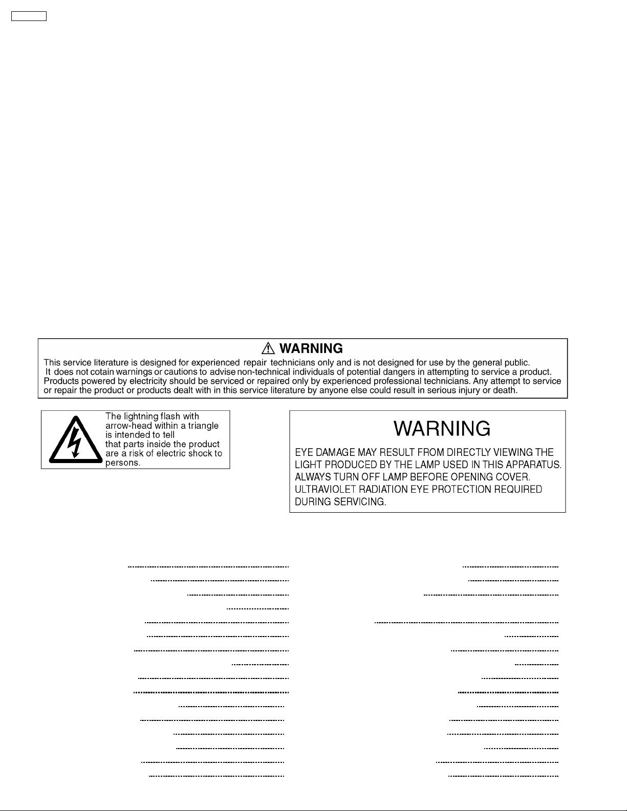
!
!
!
!
1.2. Leakage Current Cold Check
1. Unplug the AC power cord and short between the two
prongs of the AC plug with a jumper wire.
2. Set the power switch of this set to ON position.
3. Measure the resistance value with an ohmmeter between
the shorted AC plug and each exposed metallic part of the
set cabinet such as screwheads, connectors, and control
shafts. When the exposed metallic part has a return path to
the chassis, the reading should be more than 4 M!.
When the exposed metal part does not have a return path
to the chassis, the reading must be infinity.
repaired and rechecked before it is returned to the
customer because of a possibility of an electrical shock.
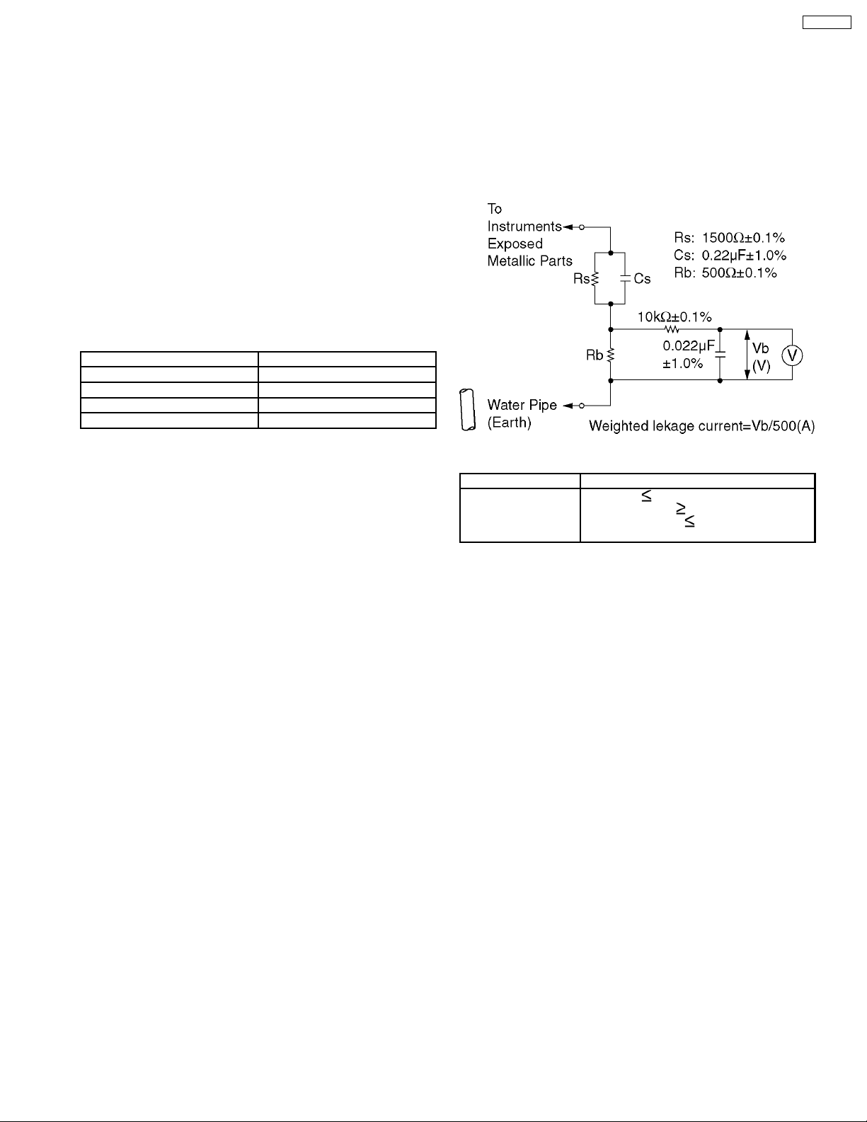
1.4. Hot-Check Circuit
Prepare the measuring circuit as shown in Fig.1.
Be sure to use a voltmeter having the performance described
in Table 1.
Fig. 1
Voltmeter
(rms reading)
Table 1
Accuracy: 2%
Input resistance:
Input capacitance:
Frequency range: 15Hz to 1MHz
Performance
1M
!
200pF
1.5. Lamp Precautions
"""" ·""""Be sure to unplug the power cord from the power outlet
when replacing the lamp.
"""" ·""""Because the lamp reaches a very high temperature during
its operation, wait until it cools completely when replacing
the lamp.
"""" ·""""The lamp emits small amounts of UV-radiation, avoid
diredt-eye contact with the light.
1.3. Leakage Current Hot Check
(See Fig.1)
1. Plug the AC power cord directly into the AC line outlet. Do
not use an isolation transformer for this check.
2. Connect the measuring circuit as shown in Fig.1. between
each exposed metallic part of the set and an earth ground
such as a water pipe.
3. Use a high impedance AC voltage meter to measure the
voltage across the resistor.
4. Measure the voltage at each exposed metallic part.
5. Reverse the AC plug inserting direction at the AC line outlet
and repeat each of the above measurements.
6. The voltage at any point must be less than 0.25Vrms.
7. A leakage current tester (SIMPSON MODEL 228 or the
equivalent) may be used to make the hot checks. In this
case, the current must be less than 500µA.
8. If the reading is more than the above value, the set must be
5
PT-52DL10
2 Functions for Safety
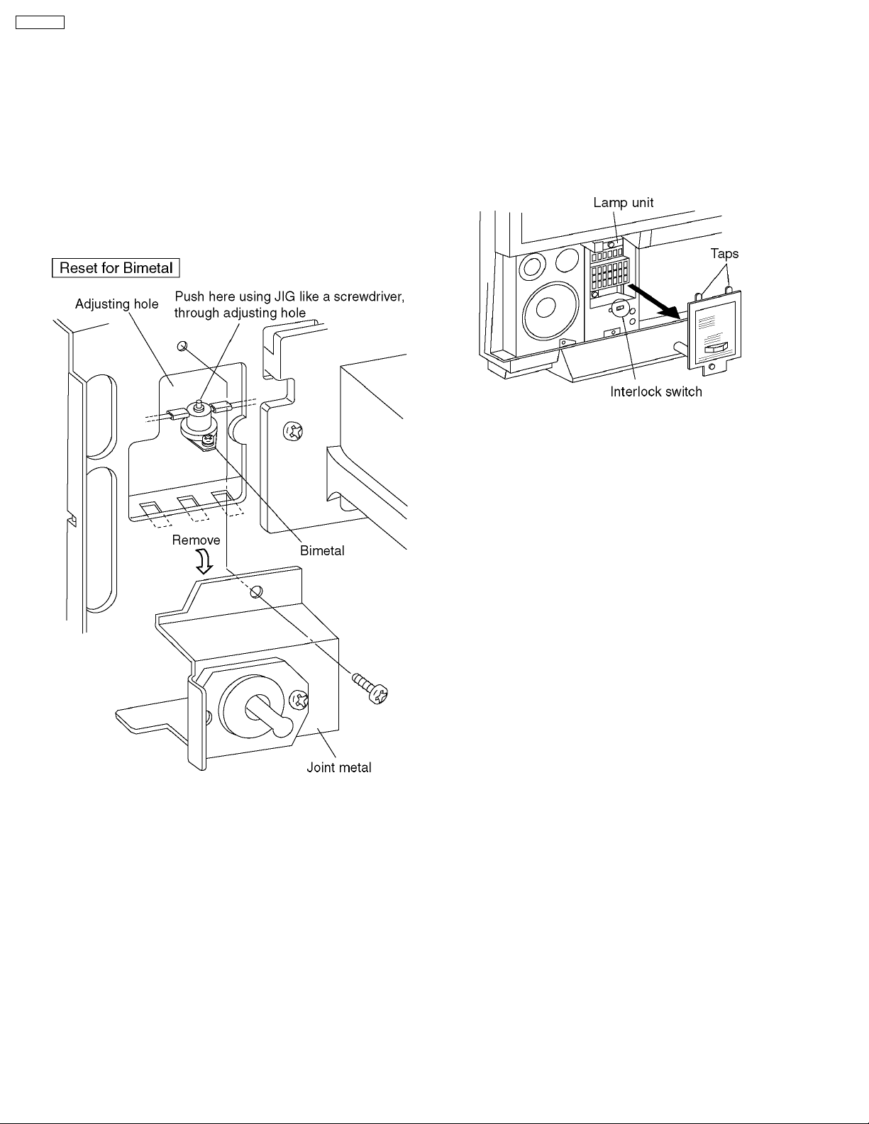
2.1. Temperature Detection for the
Lamp Unit
This projector has the bimetal contacting the lamp unit to
project the lamp. If the temperature of the lamp unit exceeds
100°C, the bimetal will operate to turn off the power.
The installed position of the bimetal is shown in the illustration.
To recover the bimetal from its off state, press the protrusion of
the bimetal unit you hear it click.
2.2. Interlock Switch
To ensure safety, this projection TV is designed so that the
power cannot be turned on without the Lamp Unit Cover or
under its imperfect installation.
If removing the Lamp Unit Cover during the operation of the
Projection TV, the power will be turned off.
6
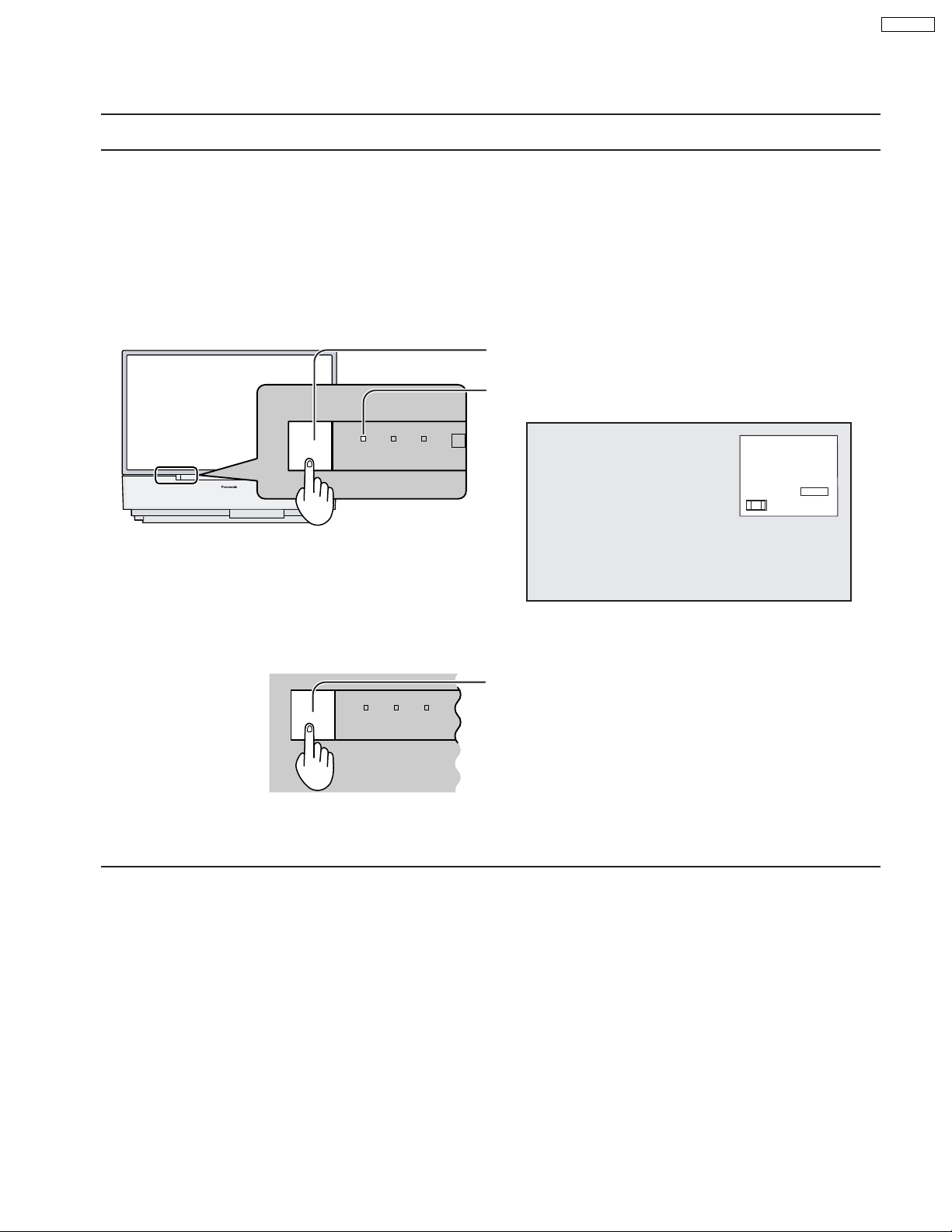
3 Customer Operation
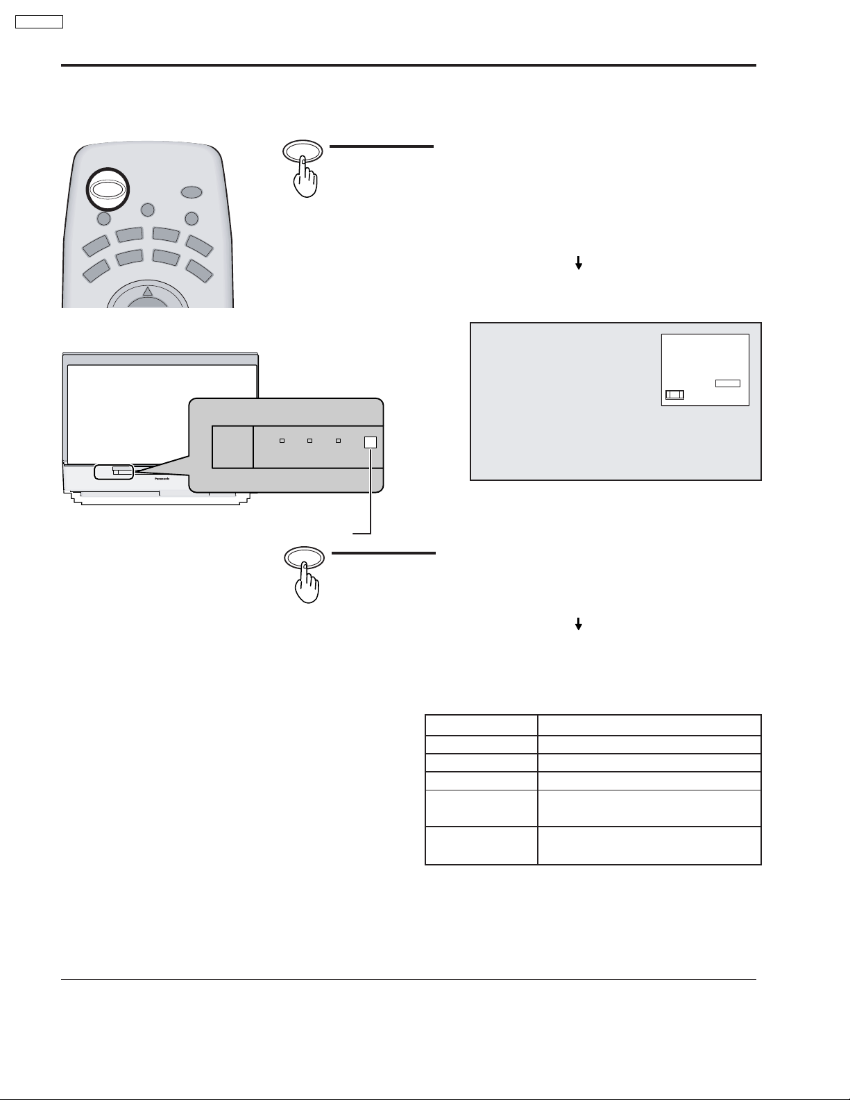
Turning the Power ON and OFF
Always be sure to follow the procedure given below to turn the projection TV power ON and OFF.
The lamp cooling fan will continue to operate for approximately 90 seconds after the power is turned off by the remote control.
•
At the same time, the power indicator will blink Orange.
Normally, use the remote control to turn the power OFF (turning the picture OFF).
Do not disconnect the power cord from the power outlet or do not open any circuit breakers while the cooling
fan is still operating.
Do not disconnect the power cord from the power outlet while in Stand-by mode.
When you want to turn on the power again immediately after turning off the power during the operation of the projection
•
TV, be sure to wait until the cooling fan stops and then turn on the power.
Setting the projection TV to Stand-by, the power indicator will light up red.
Push the Pow er switch on the projection TV to turn the power
on.
The Power Indicator will become Green and blink
(approximately 10 seconds).
POWER
R-STANDBY
G-POWER ON
LAMP
TEMP
CH123
STEREO
SAP
MONO
NORMAL
PT-52DL10
Example: The screen above is display for a while after the
projection TV is turned on. (Setting condition is an
example.)
Push the Pow er switch on the projection TV to turn the set off.
POWER
R-STANDBY
G-POWER ON
LAMP TEMP
The Power Indicator will no-illumination.
The Power Indicator will light
Power-OFF ............ Not illuminate
•
Stand-by ................ Red
•
Power-ON .............. Green
•
Note:
When the power is switched off using the POWER switch on the set, the internal cooling fan also stops operating. Therefore,
the lamp is not sufficiently
cooled and will take a while for it to turn ON again.
7
PT-52DL10
Power ON / OFF
Power (ON / OFF) button
POWER
ASPECT
MUTE TV/VIDEO
DVD
R
C
V
V
T
D
V
T
LIGHT
A
U
X
R
C
B
L
CH
POWER
C
V
R
D
B
S
POWER
R-STANDBY
G-POWER ON
LAMP TEMP
Remote Control Sensor
Push the Power button to turn the projection TV ON,
from Stand-by mode.
The projection TV must first be switched on at the wall
outlet and the Power switch.
The Power Indicator will blink Green.
Approximately 10 seconds
The Power Indicator will become Green.
CH123
STEREO
SAP
MONO
NORMAL
Example: The screen above is display for a while after
the projection TV is turned on. (Setting
condition is an example.)
POWER
Push the Power button to turn the projection TV to
Stand-by mode.
The Power Indicator will become Orange.
Approximately 90 seconds
The Power Indicator will become Red.
The Power Indicator
LED
No illuminated
Red
Green
Green blink
(approximately 10 seconds after)
Orange blink
Power – OFF (by the remote control)
(approximately 90 seconds after)
Note:
Even when the main power switch (FUNCTION SWITCH) is turned off, and the POWER indicator is not lit, the projection
TV is not completely cut off from the power if the power cable is still plugged in.
ACTION
Power – OFF
Stand – by
Power – ON
Power – ON
8
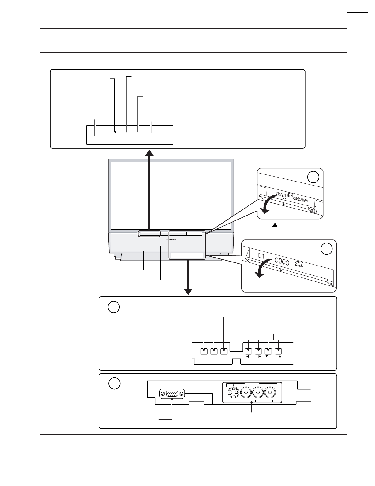
Location of Controls
Controls and Terminals on the projection TV
< FRONT >
PT-52DL10
POWER INDICATOR
R-STAND BY
G-POWER ON
POWER SWITCH
POWER
R-STANDBY
G-POWER ON
LAMP
This indicator lights up when there is a malfunction with the
lamp unit
TEMP
This indicator lights up when there is an abnormal temperature
in the unit
Remote Control Sensor
LAMP TEMP
Press the
front cover to open.
A
Open
mark on the center of the
B
Lamp unit
Speaker panel
A
B
PC Input terminal
Input mode selection buttons
Action button
Menu button
MENU ACTION
PC INPUT
Open
Volume up(+) / down(–) buttons
Channel up / down
buttons
VOLUME
INPUT 4
S-VIDEO VIDEO
CHANNELTV/VIDEO
L-AUDIO-R
Input4 terminals
Video camera and TV game cable terminal
9
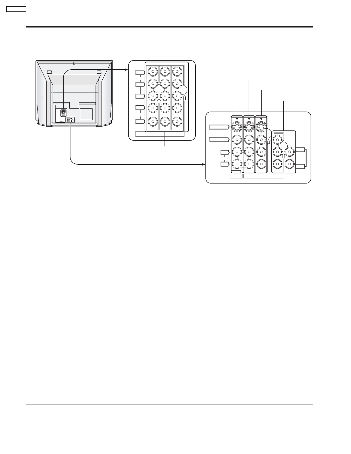
PT-52DL10
< REAR >
Y
VIDEO
P
P
Monitor out terminals
Input1 terminals
B
R
Input2 terminals
Input3 terminals
Y
VIDEO
PB
P
R
L
AUDIO
R
213
INPUT
COMPONENT VIDEO
S-VIDEO
VIDEO
L
L
TO
AUDIO
AUDIO
ANT1 ANT2SPLIT
AMP
OUT
R
R
213
PROG
INPUT
OUT
L
AUDIO
R
COMPONENT VIDEO
213
INPUT
S-VIDEO
VIDEO
Component signal input
L
AUDIO
R
PROG
OUT
213
INPUT
L
TO
AUDIO
AMP
R
10
Location of Controls
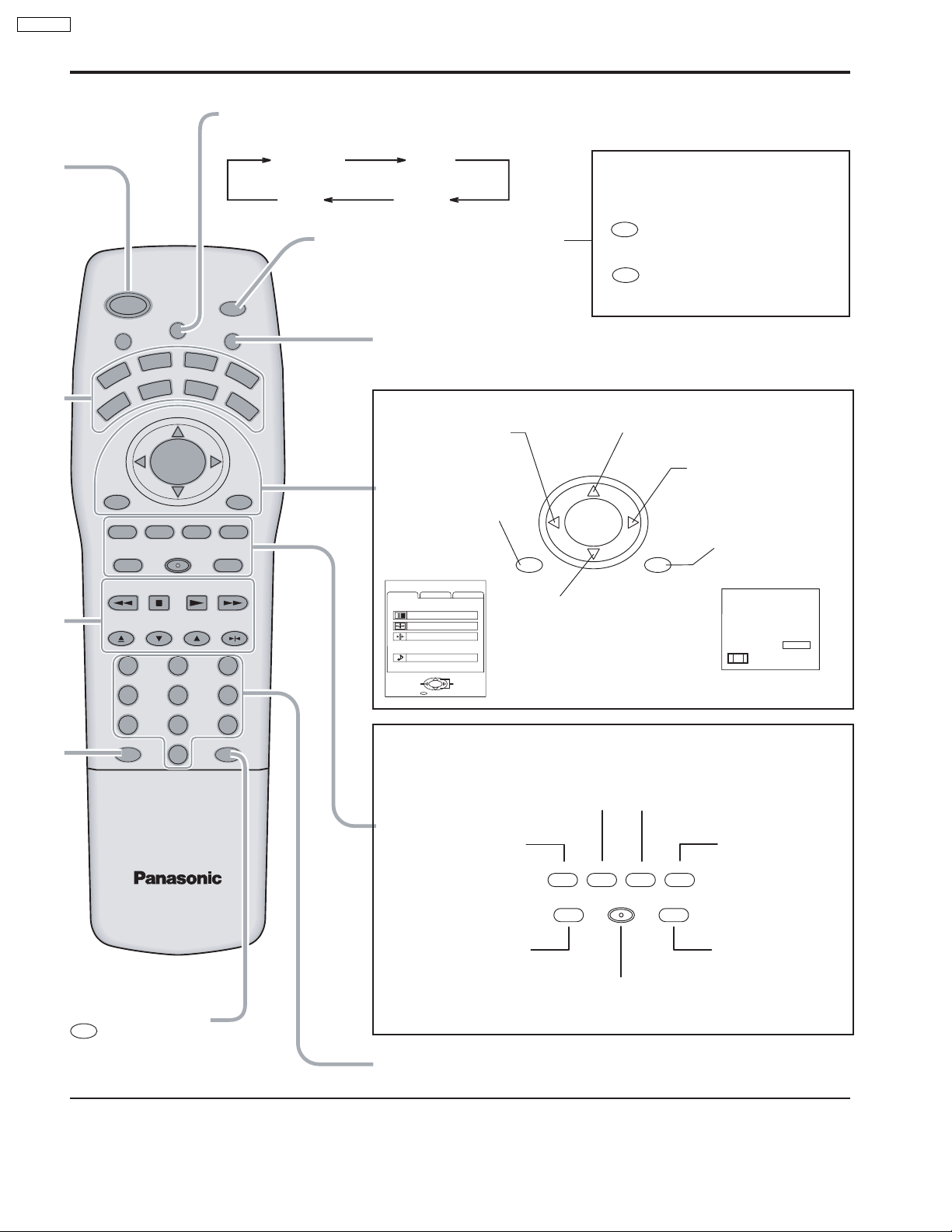
Illuminated Remote Control
Power button
Press to turn the projection TV ON or OFF.
Note:
The TV’s power cord must first be plugged into the wall outlet and then turned on at the
POWER switch (standby mode).
MUTE button
Push this button to mute the sound.
Mode Selection buttons
Selects the operation mode for the remote control.
Digital Video Disk Mode Selection for Remote Control
VCR Mode Selection for Remote Control
TV Mode Selection for Remote Control
Digital TV Mode Selection for Remote Control
VCR
TV
DVD
DTV
Aux Mode Selection for Remote Control
AUX
CBL
Receiver / Amplifier Mode Selection
RCVR
for Remote Control
DBS
Digital Broadcasting Satellite for
Remote Control
Cable TV Mode Selection for Remote Control
PT-52DL10
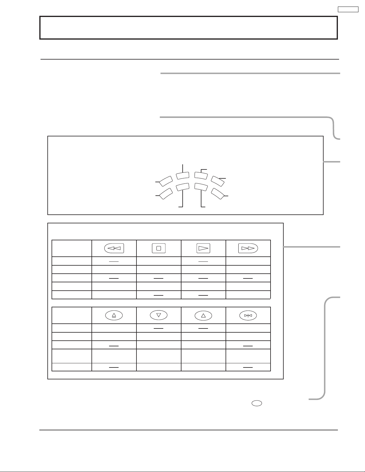
Operating of other Device
Buttons
TV
VCR
REW
CABLE / DBS
DVD / LD / CD
RCVR
Skip Search REW
Surround –
Buttons
TV
VCR
Split Freeze
TV/VCR switch
CABLE / DBS
DVD / LD / CD
Open / Close
RCVR
Split Search
STOP
STOP
Channel down
Channel down
Slow - / LD-sideB
/ Random
Center –
PLAY
PLAY
Channel up
Channel up
Slow + / LD-sideA
/ Repeat
Center +
Split ON / OFF
FF
Skip Search FF
Surround +
Split Swap
Pause
Still / Pause
R-TUNE
R-TUNE button
Switches to previously view
to channel or video mode.
11
PT-52DL10
Location of Controls
ASPECT button
Change of screen size.
AUX
C
B
GAME
PLAY
LIGHT
L
INFO/RECALL
RH-SPLIT
GUIDE
SPLIT
SWAP
PAUSE
R
FF
POWER
MUTE TV/VIDEO
VC
TV
VOL VOL
MENU
AV-ADJ
REW
FREEZE
TV/VCR
OPEN/CLOSE STILL
R
EXIT
ASPECT
D
V
D
V
T
D
CH
ACTION
CH
NORMAL
VCR REC
SEARCH
STOP
VCR/DBS CHANNEL
SLOW
123
456
NORMAL JUST
FULL ZOOM
Lights the remote control buttons
The selected button blinks when lit.
C
VR
DBS
Turning ON and OFF the remote
control illumination
R-TUNE
Remote control illumination
can be turned ON and OFF
+
INFO/RECALL
by pressing the INFO/
RECALL button while
pressing the
R-TUNE button.
TV/VIDEO buttons
This input mode changes each time this button is pressed.
Changes to the next channel up
Moves cursor upward during menu mode.
Reduces volume
Moves cursor to the
left during menu
mode.
CH
Increase volume
Moves cursor to the
right during menu
Displays menu
VOL VOL
ACTION
mode.
Press the Menu
button to display
the Menu screen.
MENU
ADJUST
PICTURE ADJUST
POSITION/SIZE
CLOCK
AUDIO ADJUST
PAGE
CUSTOM
PICTURE
AUDIO
ACTION
EXIT
SET UP
SELECT
MENU
CH
INFO/RECALL
Changes to the next
channel down
Moves cursor downward
during menu mode.
The screen below
is displayed for 10
seconds.
CH123
STEREO
SAP
MONO
NORMAL
789
R-TUNE PROG
PROG
PROG button
0
NORMALIZATION button
Each setting in the MENU
screen is reset to its standard
values. (PICTURE, AUDIO,
POSITION / SIZE / CLOCK)
AV ADJUSTMENT
button
AV-adjustments are
displayed.
AV-ADJ
Returns to normal
viewing from the
MENU screen.
Previous before item
VCR Record button
NORMAL
EXIT
GAME button
GAME
VCR REC
RH-SPLIT
GUIDE
RH-SPLIT button
Operates the right
screen.
GUIDE button
for DBS.
in MENU.
Direct program number
selection buttons
12
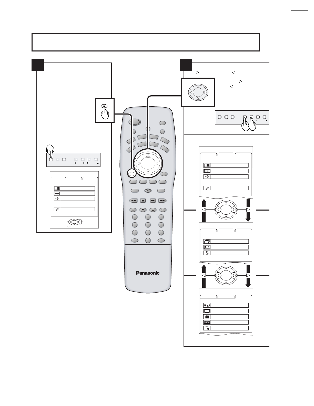
Flow Chart of Main menu
PT-52DL10
1
If the MENU button is pressed, the
MENU screen will be displayed.
If the MENU button is pressed
once more while the menu screen
is displayed, the MENU screen
will be cleared.
The MENU button on the main
body can also be pressed to
display the MENU screen.
MENU VOLUME
ACTION TV/VIDEO
MENU
ADJUST
CUSTOM
PICTURE
PICTURE ADJUST
POSITION/SIZE
CLOCK
AUDIO
AUDIO ADJUST
ACTION
PAGE
EXIT
CHANNEL
SET UP
SELECT
MENU
ASPECT
CH
CH
SLOW
AUX
CBL
GAME
PLAY
LIGHT
INFO/RECALL
RH-SPLIT
GUIDE
SPLIT
SWAP
PA U S E
POWER
MUTE TV/VIDEO
DVD
R
VC
DTV
TV
VOL VOL
ACTION
MENU
NORMAL
AV-ADJ
VCR REC
EXIT
SEARCH
AUDIO ADJUST
REW
STOP
FREEZE
TV/VCR
VCR/DBS CHANNEL
OPEN/CLOSE STILL
123
456
789
R-TUNE PROG
0
RCVR
DBS
FF
2
Select MENU desired by pushing Right
” button or Left “
“
CH
ACTION
VOL VOL
CH
” button.
Right “
” button
The
Left “
main body can also be
used to select items on
the MENU screen.
MENU VOLUME
ACTION TV/VIDEO
MENU
ADJUST
CUSTOM
SET UP
PICTURE
PICTURE ADJUST
POSITION/SIZE
CLOCK
AUDIO
ACTION
MENU
ADJUST
CUSTOM
SET UP
CHANNEL SEARCH
SLEEP TIMER 0
AUDIO MODE
” button and
on the
CHANNEL
13
ACTION
MENU
ADJUST
CUSTOM
LANGUAGE
PROGRAM CHANNELS
LOCK
CLOSED CAPTION
VIDEO
SET UP
PT-52DL10
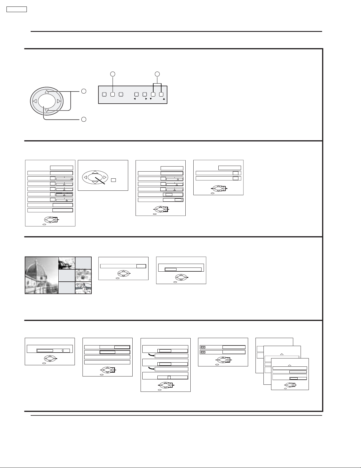
Flow Chart of Main menu
CH
VOL VOL
ACTION
CH
TO PICTURE
ADJUST menu
PICTURE ADJ.
PICTURE MENU
PICTURE
BRIGHTNESS
COLOR
TINT
SHARPNESS
COLOR TEMP
BLACK EXT.
NORMAL
DYNAMIC
— +
30
— +
0
— +
0
0
— +
10
COOL
OFF ON
ACTION
EXIT
SELECT
TO CHANNEL
SEARCH screen
1
MENU VOLUME
The CHANNEL button on the
main body can also be pressed
2
to select items in the MENU
screen.
TO POSITION/
SIZE
POSITION/SIZE
NORMALIZE
TO SLEEP TIMER
adjust screen
SLEEP TIMER
SLEEP TIMER
2
ACTION TV/VIDEO
NORMAL
SIZE
1
EXIT
TO A UDIO
ADJUST menu
AUDIO ADJ.
AUDIO MENU
BASS
TREBLE
BALANCE
SPATIALIZER
SPEAKERS
CHANGE
0
CHANGE
1
CHANNEL
NORMAL
AUTO
— +
6
— +
4
— +
0
OFF ON
OFF ON
SELECT
EXIT
TO A UDIO MODE
adjust screen
AUDIO MODE
AUDIO MODE
STEREO
EXIT
SAP
TO CLOCK
CLOCK
CLOCK PHASE
DOT CLOCK
ADJUST
When the set is connected to the
•
NORMAL
0
0
ACTION
SELECT
EXIT
PC, CLOCK can be adjusted.
MONO
CHANGE
TO LANGUAGE
selection screen
LANGUAGE
LANGUAGE
ENGLISH
FRAN
CHANGE
EXIT
TO PROGRAM
CHANNELS adjust screen
PROGRAM CHANNELS
AIS
MODE TV CABLE
ANTENNA ANT1 ANT2
AUTO PROGRAM
MANUAL PROGRAM
CHANGE
EXIT
ANTENNA switching for
•
PROGRAM CHANNEL is
possible only during TV mode .
SELECT
TO LOCK
selection screen
LOCK
MOTION PICT. STATUS
TV PARENTAL STATUS
ENTER CODE FIRST
CHANGE
OFF ON
CHANGE SETTING
OFF ON
CHANGE SETTING
— — — —
SELECT
EXIT
14
TO CLOSED CAPTION
selection screen
CLOSED CAPTION
ON MUTE
MODE
CHANGE
EXIT
NO
OFF
SELECT
TO VIDEO
adjust screen
VIDEO
VIDEO NR
DVC PLAYBACK MODE
CHANGE
VIDEO
OFF ON
NORMAL FRAME
3D Y/C FILTER
VIDEO
ID-1
VIDEO INPUT LABEL
SCAN MODE
EXIT
GAME
480p COLOR MATRIX
CHANGE
EXIT
CHANGE
PAGE 1 / 3
OFF ON
OFF ON
SELECT
TV
EXIT
PAGE 2 / 3
GAME
SDTV HDTV
SELECT
PAGE 3 / 3
VIDEO 1
SELECT
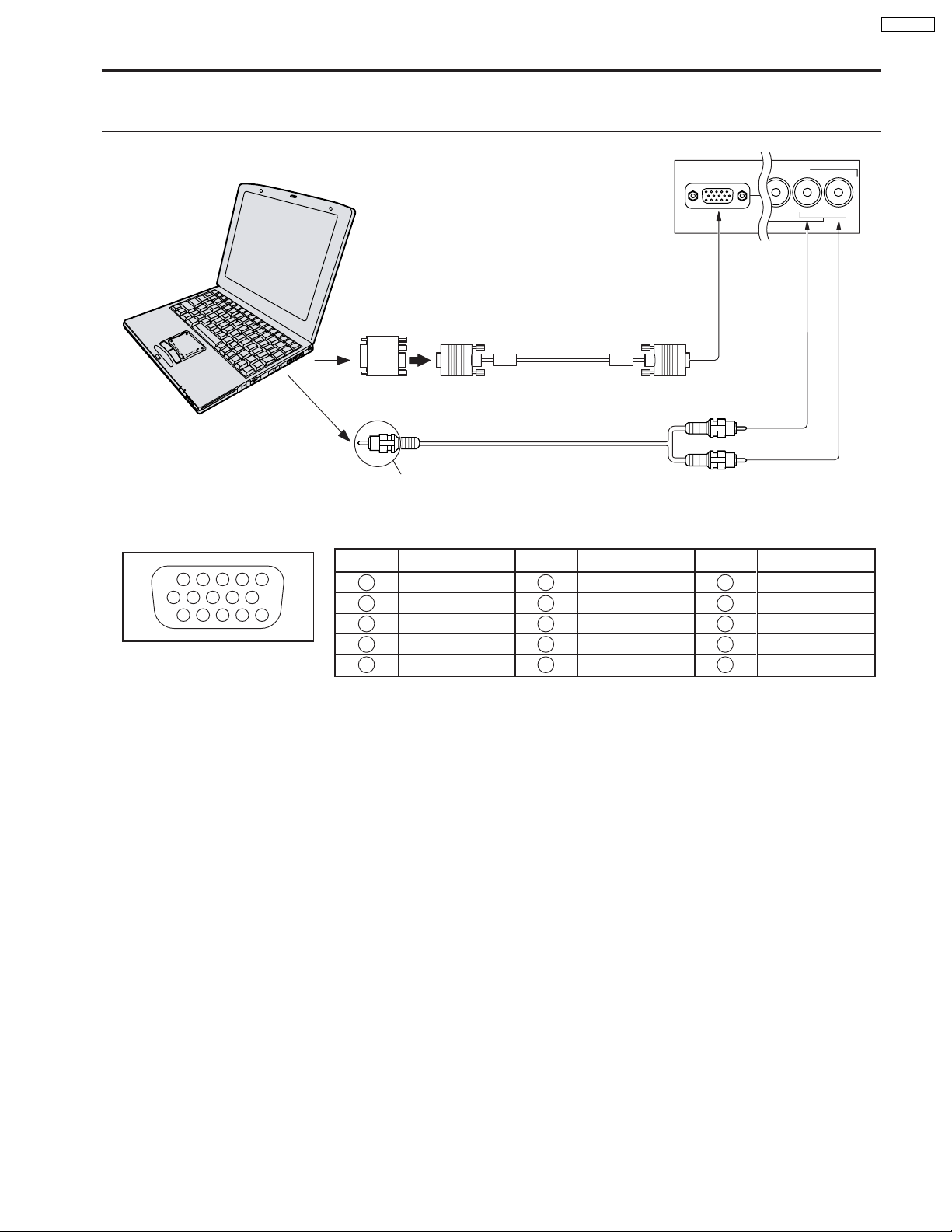
Installation
How to connect the PC Input Terminals
COMPUTER
PC INPUT
INPUT
VIDEO
PT-52DL10
4
L-AUDIO-R
Conversion adapter (if necessary)
Signal Names for D-SUB 15P Connector
Pin No.
45
10
15 14 13 12 11
Pin Layout for PC Input
Terminal
1
2
67839
1
2
3
4
5
D-SUB 15P
RGB
PC cable
(supplied)
TSXF147 (1.5 m)
Audio
Connect a cable which matches
the audio output terminal on the computer.
Signal Name
R
G
B
GND (Ground)
GND (Ground)
Pin No.
6
7
8
9
10
Signal Name
GND (Ground)
GND (Ground)
GND (Ground)
NC (not connected)
GND (Ground)
2 × RCA plug
Pin No.
11
12
13
14
15
Signal Name
GND (Ground)
SDA
HD / SYNC
VD
SCL
Notes:
(1) The PC input terminals are DDC1/2B-compatible. If the computer being connected is not DDC1/2B-compatible, you will
need to make setting changes at the computer at the time of connection.
(2) Some PC models cannot be connected to the set.
(3) An adapter is required to use the PC cable (D-SUB 15P) to connect a Macintosh computer to the set.
(4) There is no need to use an adapter for computers with PC / AT compatible D-SUB 15P terminal.
(5) The computer shown in the illustration is for example purposes only.
(6) Additional equipment and cables shown are not supplied with this set.
(7) The picture will become dark if a PC signal with a vertical scanning frequency of 62 Hz is input. To obtain the optimum
picture quality with the projection TV, a vertical scanning frequency of 60 Hz is recommended.
(8) Do not set the horizontal and vertical scanning frequencies for PC signals which are above or below the specified
frequency range.
15
PT-52DL10
Installation
Analog RGB signals that can be input
The table below lists the different types of analog RGB signals that can be input.
If a signal which differs greatly from any of the types listed below is input, the picture image may not be displayed correctly ,
or black background may displayed.
Display mode name
VGA400
VGA480
SVGA
XGA
No. of dots (H × V)
640 × 400
640 × 400
640 × 480
640 × 480
640 × 480
640 × 480
640 × 480
800 × 600
800 × 600
800 × 600
800 × 600
800 × 600
800 × 600
1024 × 768
1024 × 768
1024 × 768
Horizontal scanning
frequency (kHz)
24.8
31.5
31.5
35.0
37.9
37.5
43.3
32.1
35.2
37.9
48.1
46.9
53.7
48.4
56.5
60.0
Vertical scanning
frequency (Hz)
56.4
70.1
59.9
66.7
72.8
75.0
85.0
51.0
56.3
60.3
72.1
75.0
85.1
60.0
70.1
75.0
MAC16
Note:
The number of dots for this set is 800 × 600 for NORMAL display. Number of dots other than 800 × 600 in the above data,
will be converted to 800 × 600 (with the exception of MAC 16, which will be displayed in 832 × 624 dots).
832 × 624
49.7
74.6
16
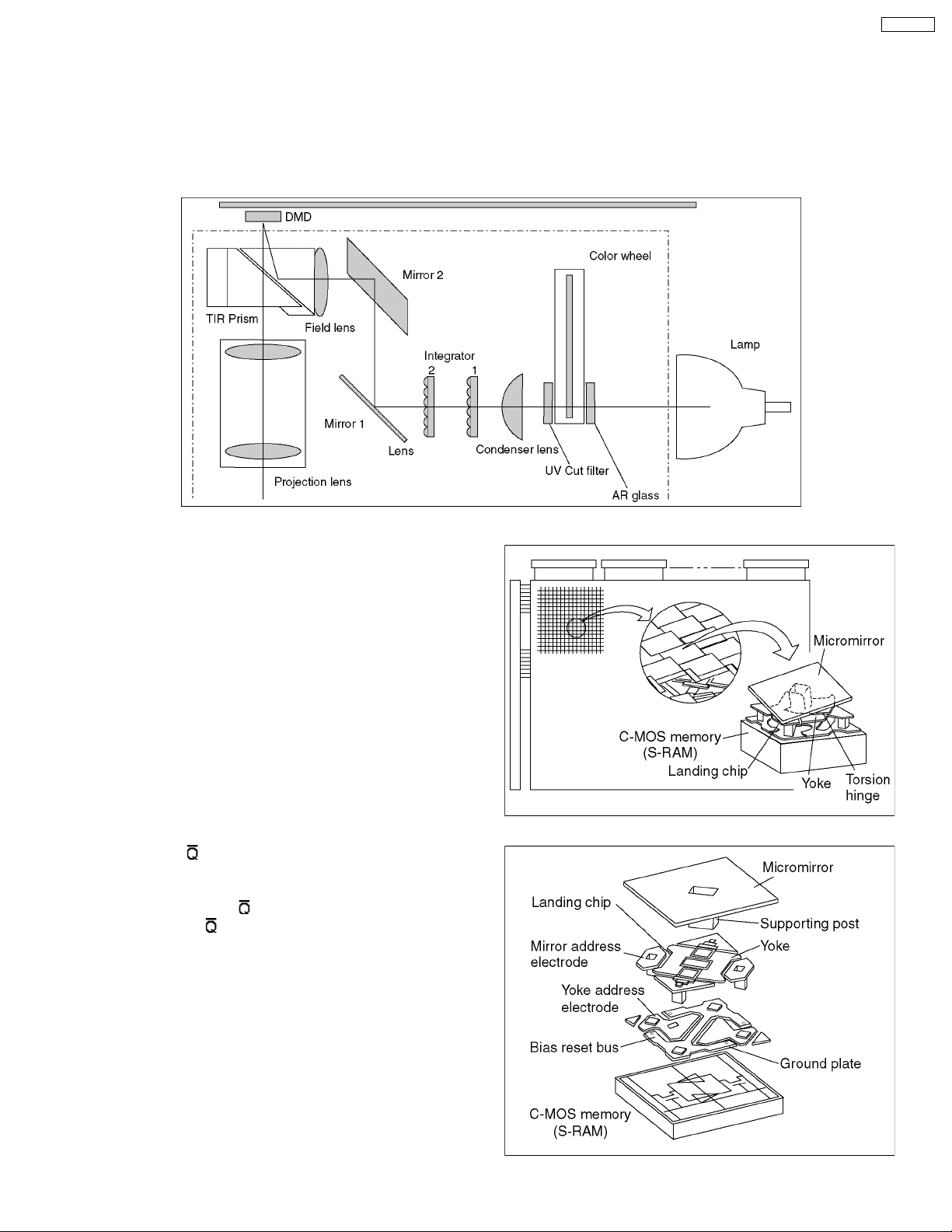
4 New functions on this projector
4.1. DLP™ Projector
The DLP™ projector employs a newly developed component called the DMD™ element. This element is made up of extremely
small mirrors (13 microns square) arrayed on a silicon board. By digitally controlling the element, the projector controls the direction
that light is reflected off its mirrors, focusing the reflected light using a prism and composing an image on the screen using a lens.
Fig.2 shows the optic system of a DLP™ projector equipped with one DMD™ element.
PT-52DL10
4.2. DMD™ element structure
In a DMD™, from 100,000 to 1 million mirrors 13 microns
square (DMD™ elements) are arrayed as shown in Fig. 3.
A single DMD™ element (single mirror) forms one picture
element (pixel). Each DMD™ element is constructed as shown
in Fig. 4 at right. The micromirror is supported by a central
support post, and the post rides on panel called a yoke.
The CMOS memory element directly below the micromirror
corresponding to each image pixel inclines the micromirror by
± 10°.
For example, if the CMOS memory element output is given the
instruction Q:1,
Q is charged with static electricity, tilting so that the 2 ends
supported by the support from a diagonal line center.
Conversely, if A:0,
corresponding to [
speed, the time required for a change of direction is about 10
microseconds.
:0, then the side of the yoke corresponding to
:1 is the instruction, the side
] tilts. Because the unit operates at high
Fig.2
Fig. 3
In this way, the micromirror parallel to the yoke is operated by
binary control (PWM modulation) corresponding to “1” or “0”.
Fig. 4
17
PT-52DL10
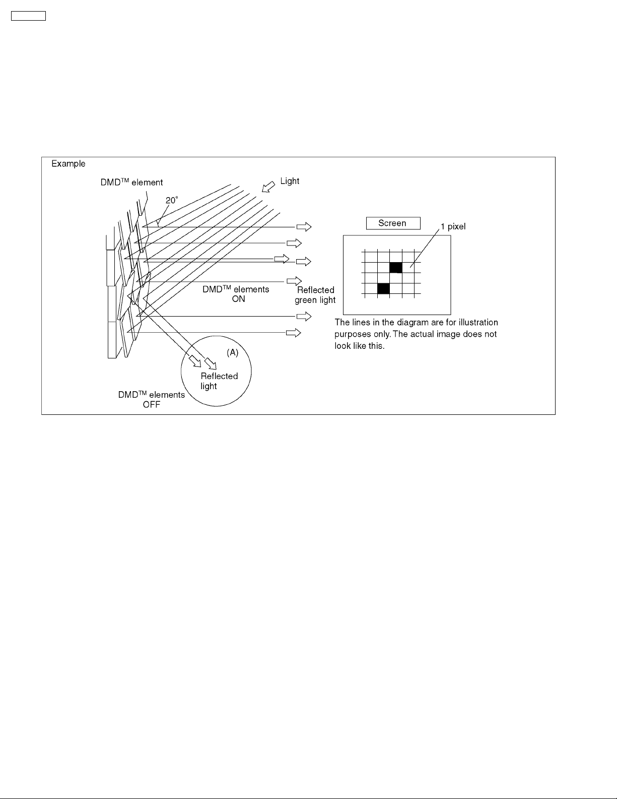
4.3. DMD™ element operation
As described earlier, in DMD™ operation, a single image is formed by digitally controlling the light reflected from the element
surface (light modulation) by switching the device on (light reflected by micromirror is projected on the screen) or off (no projection)
and by bringing each micromirror into position with each pixel.
As shown in Fig. 5, light is projected onto the DMD™ element at an angle 20° from horizontal. If the DMD™ element is OFF, the
light reflected by the micromirror (A) does not enter projection lens, and the matching point on the screen appears black. If the
DMD™ element is ON, the light reflected by the micromirror passes through the projection lens and is projected brightly on the
screen. By adjusting the length of time for micromirror reflection, ti is possible to create 256 gradations for each color; as a result,
1.67 million colors can be formed by combining the 3 colors.
Fig. 5
18
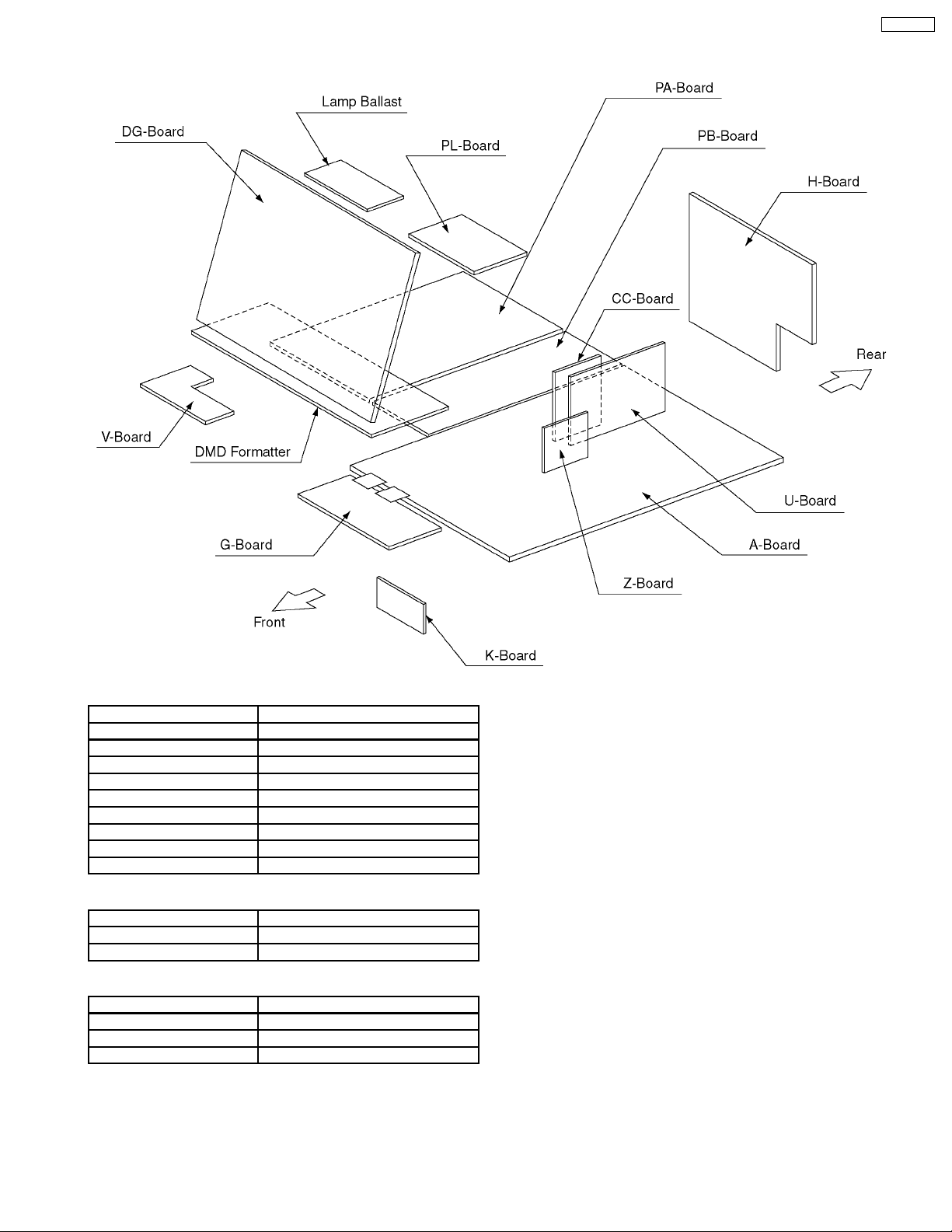
5 Chassis Board Layout
PT-52DL10
Chassis Block
Board Name Board Designation
A-Board Main
CC-Board C.C. V/chip
G-Board Front Input
H-Board Rear Input, AV switch
PA-Board Power for Digital Boards
PB-Board Power for Analog Boards
PL-Board Line filter
U-Board MPU
Z-Board Audio
Control Block
Board Name Board Designation
V-Board Power SW, LED
K-Board Front Operation
Optical Block
Board Name Board Designation
DG-Board Digital Core
DMD Formatter DMP Formatter
Lamp Ballast Lamp Power Unit
19
PT-52DL10
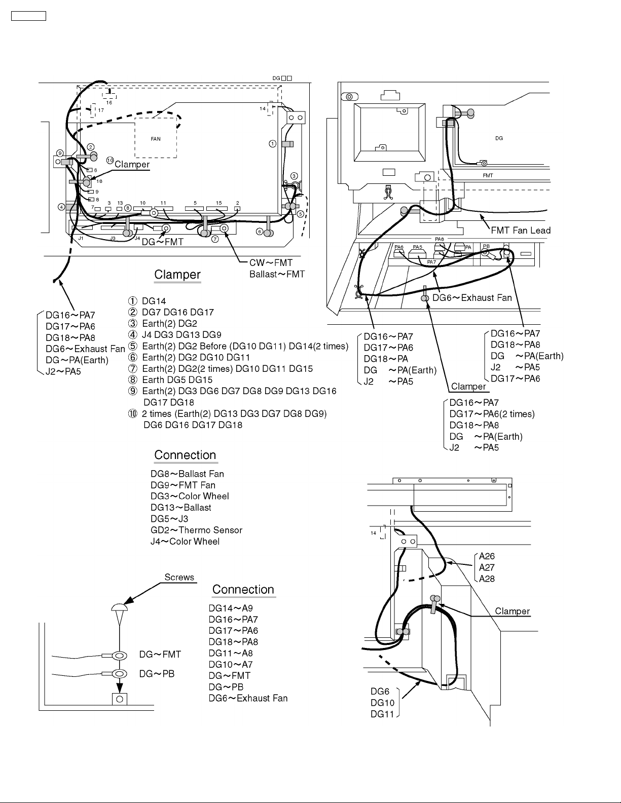
6 Location of Lead Wiring
6.1. Location of Lead Wiring (DG)
20
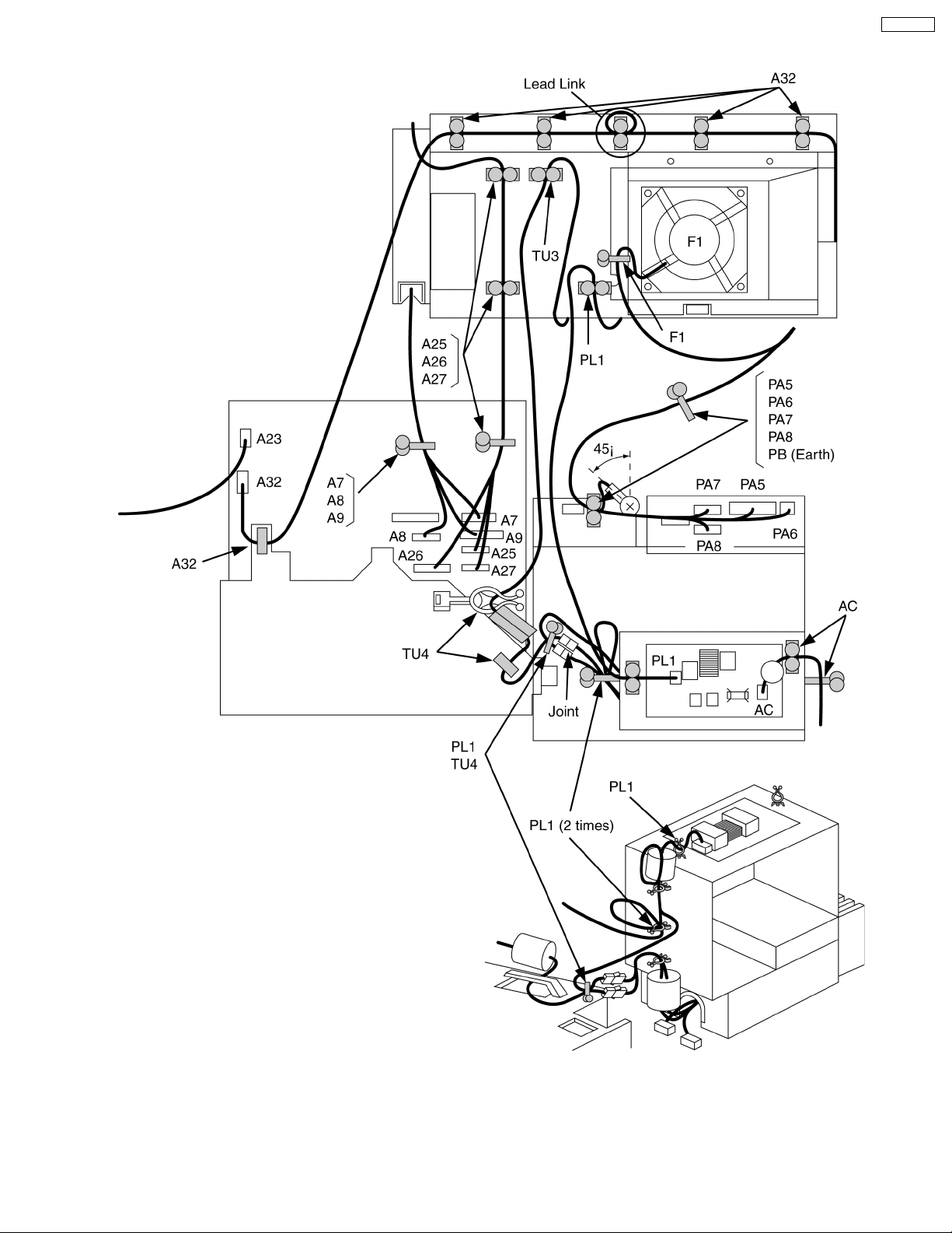
6.2. Location of Lead Wiring (Rear)
PT-52DL10
21
PT-52DL10
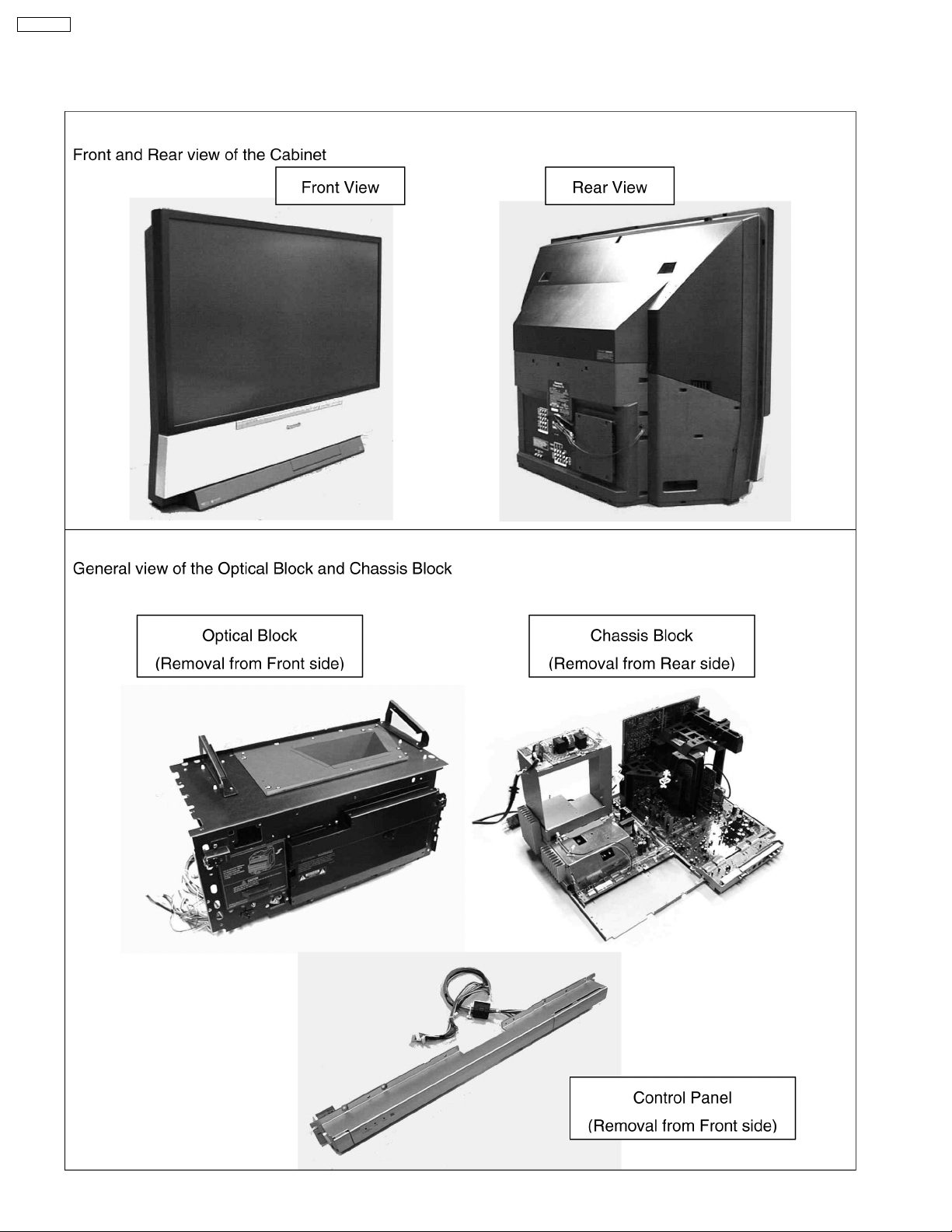
7 Disassemble for Service
7.1. View of Front/ Rear of the Cabinet, Optical Block/ Chassis Block
22
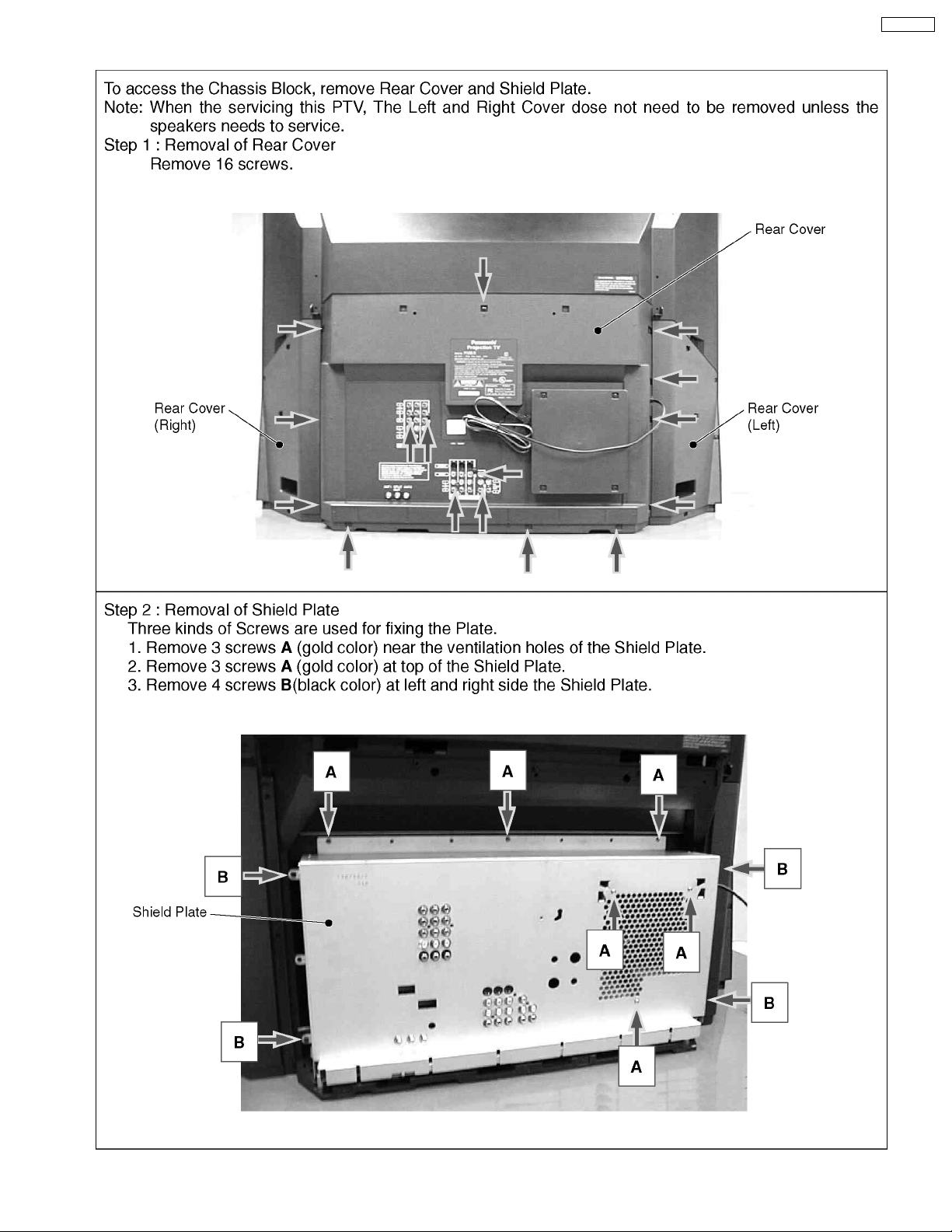
7.2. Removal of Rear Cover and Shield Plate
PT-52DL10
23
PT-52DL10
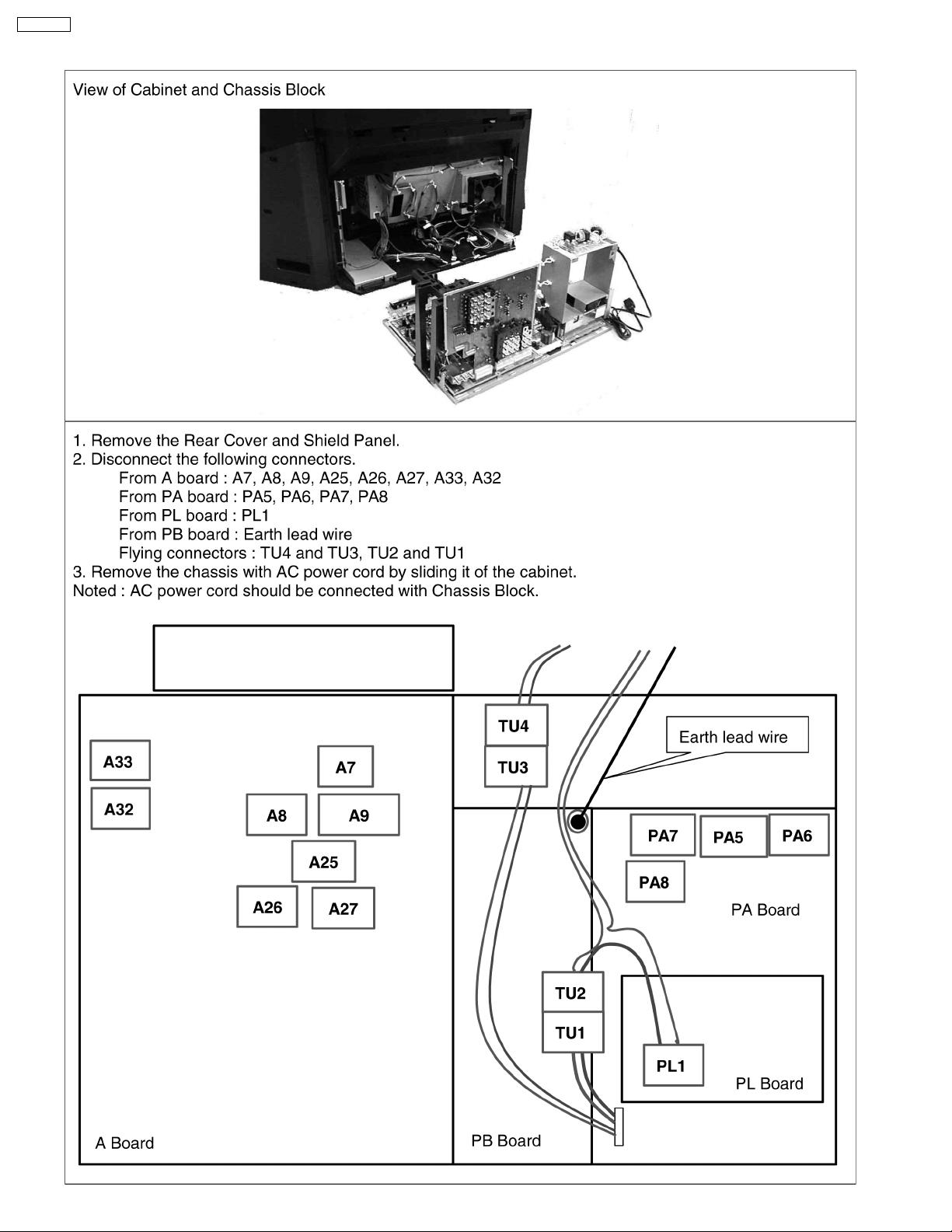
7.3. Removal of Chassis Block
24
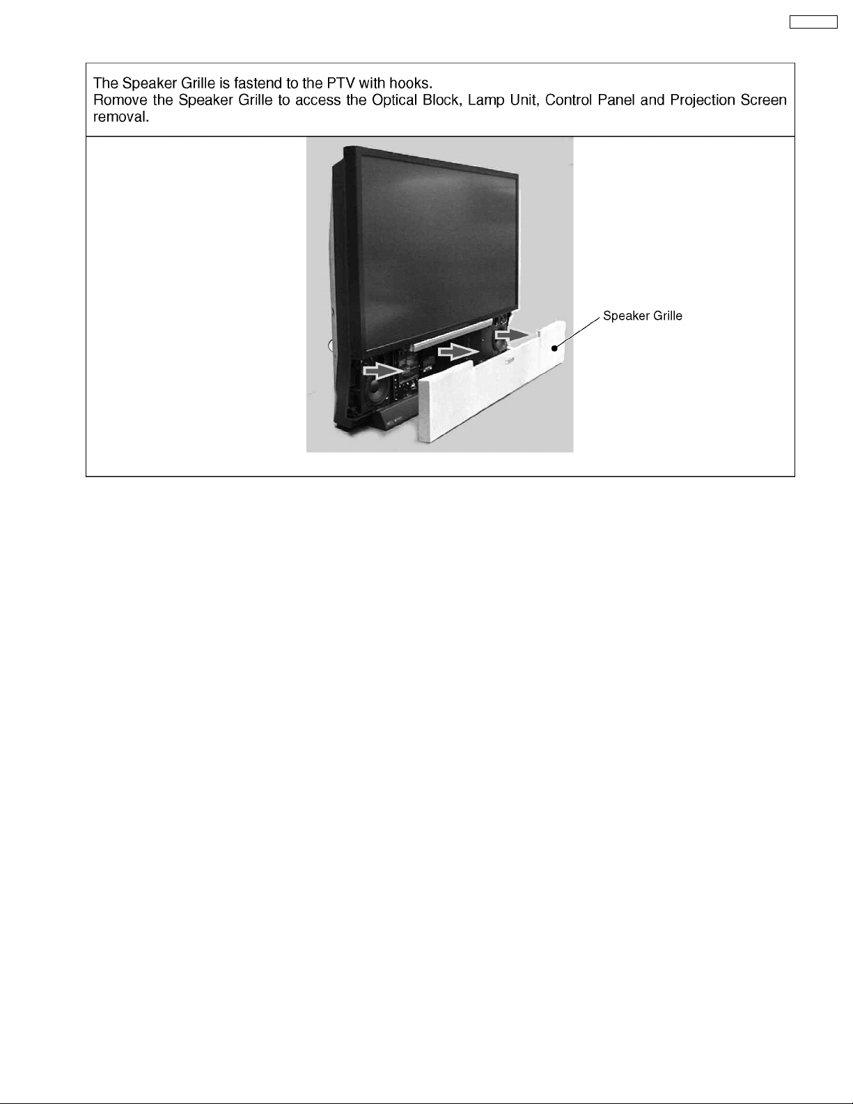
7.4. Removal of Front Decorative Speaker Grille
PT-52DL10
25
PT-52DL10
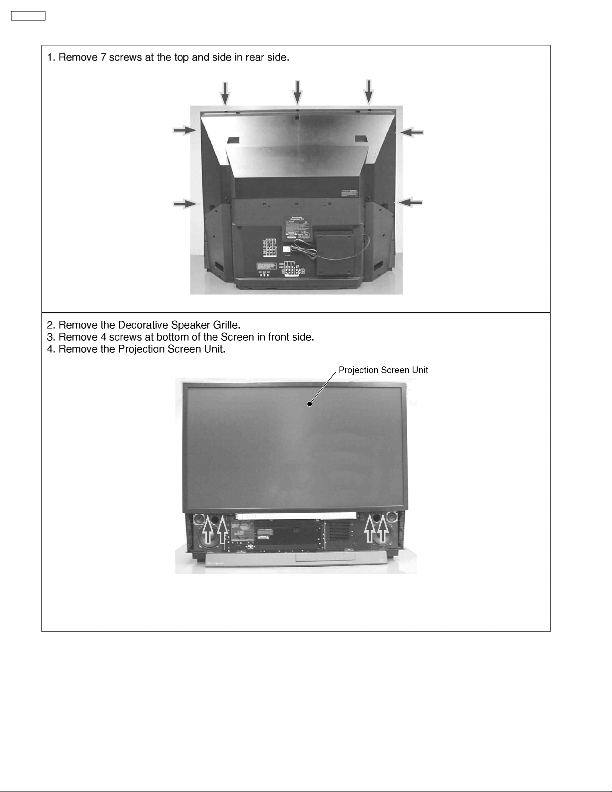
7.5. Removal of Projection Screen Unit
26
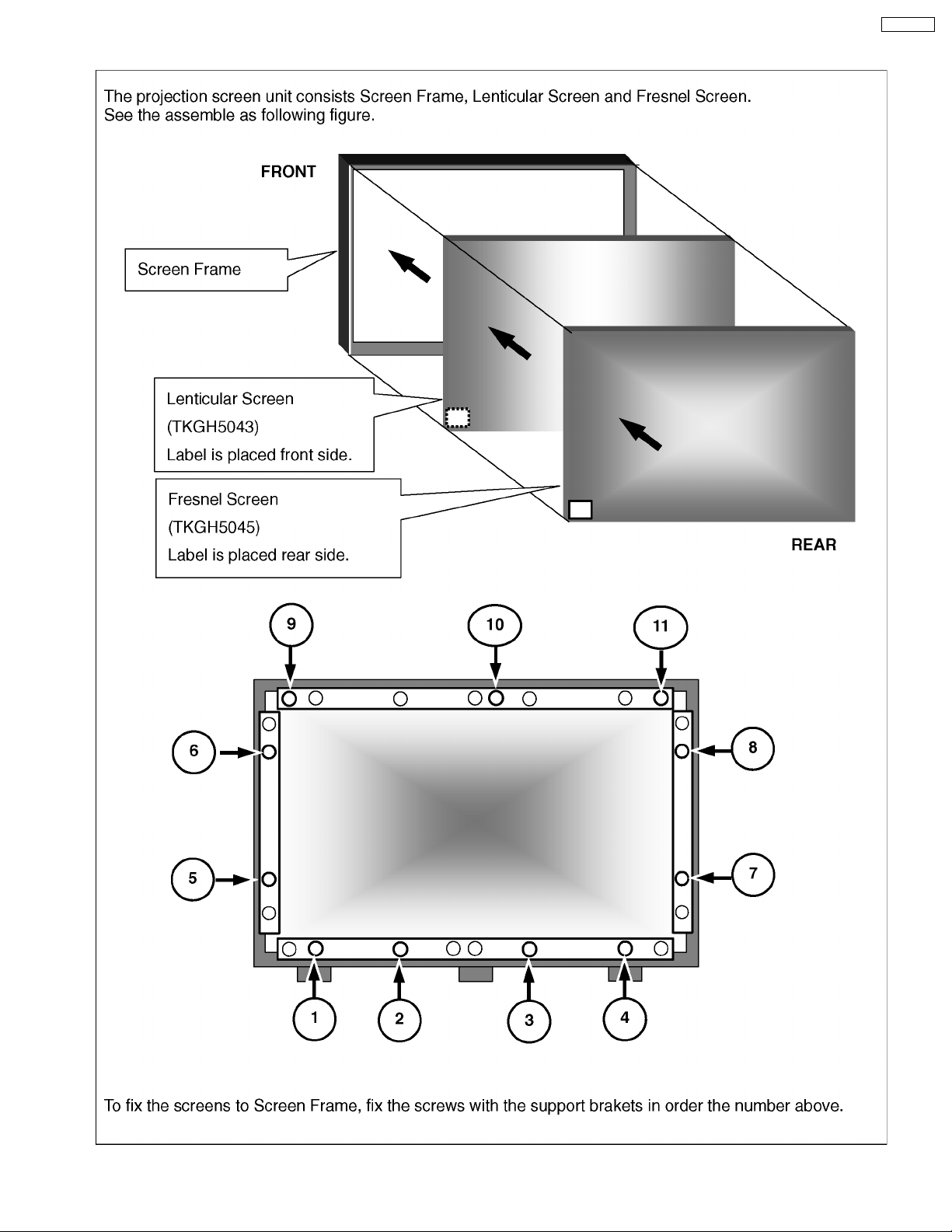
7.6. Projection Screen Assembly
PT-52DL10
27
PT-52DL10
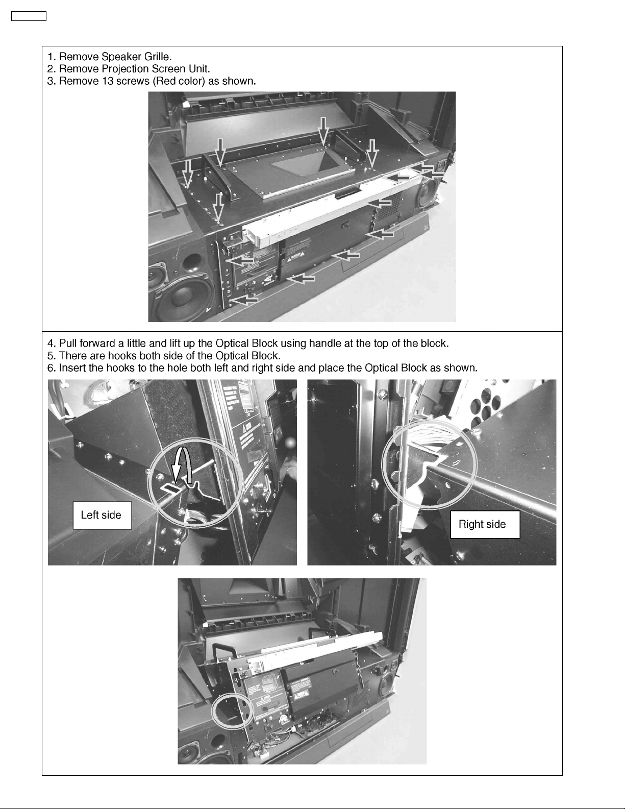
7.7. Service Position for Optical Block
28
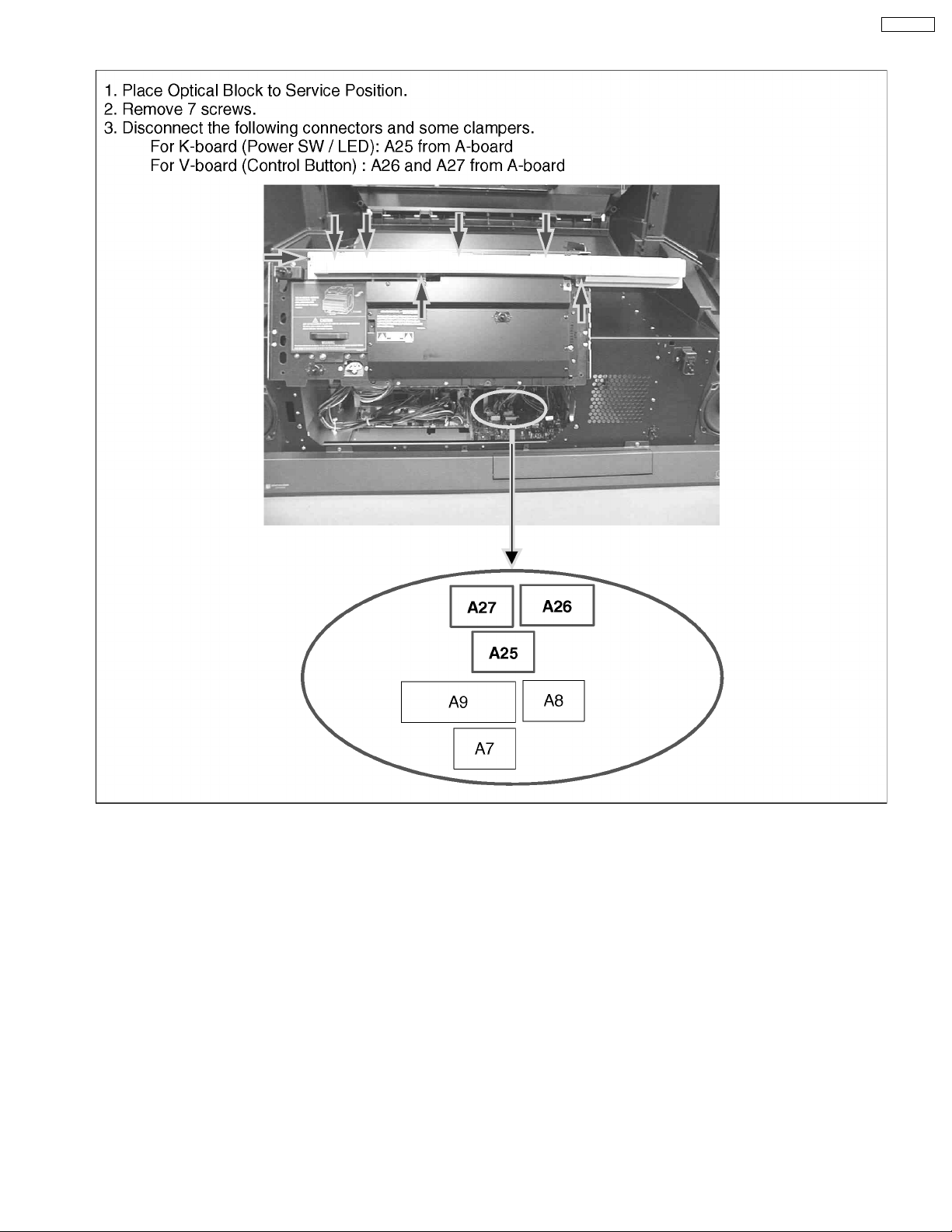
7.8. Removal of Control Panel
PT-52DL10
29
PT-52DL10
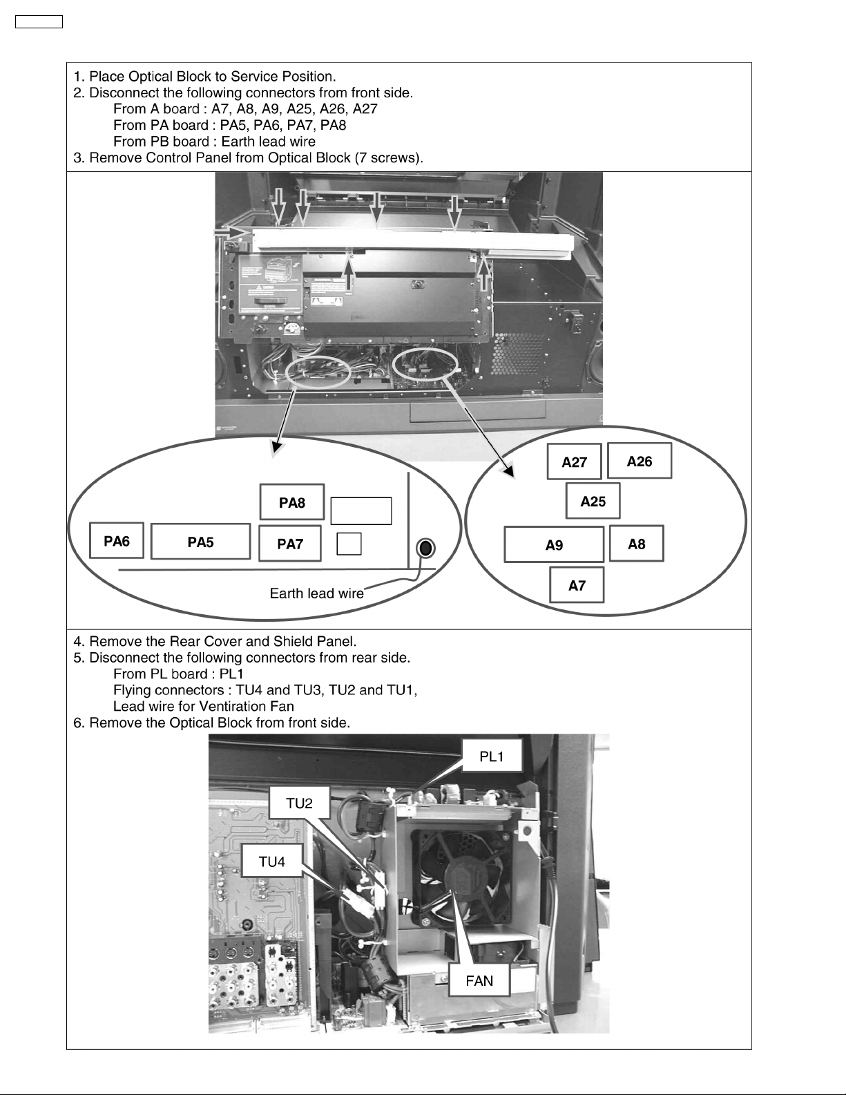
7.9. Removal of Optical Block
30
 Loading...