

M
T
P
L
D
Y
G
LO
O
HN
C
TE
TS
N
E
M
RU
T
NS
S I
A
X
TE
A
T
R
Z
I
L
A
I
T
A
O
P
E
S
ER
T
S
-D
3
V
0p
2
T
7
/
i
0
D
08
1
E
L
H
IB
T
A
P
M
O
C
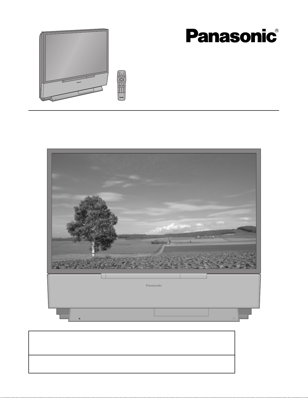
Projection Television
Operating Instructions
Model No.
PT-52DL10
SPATIALIZRT
3-D STEREO
HD
TV
COMPATIBLE 1080 i / 720p
For assistance, please call : 1-888-VIEW PTV(843-9788)
or send e-mail to : consumerproducts@panasonic.com
or visit us at www.panasonic.com (USA)
For assistance, please call : 787-750-4300
or visit us at www.panasonic.com (Puerto Rico)
DLP
A TEXAS INSTRUMENTS TECHNOLOGY
TM
TQBC0215-1
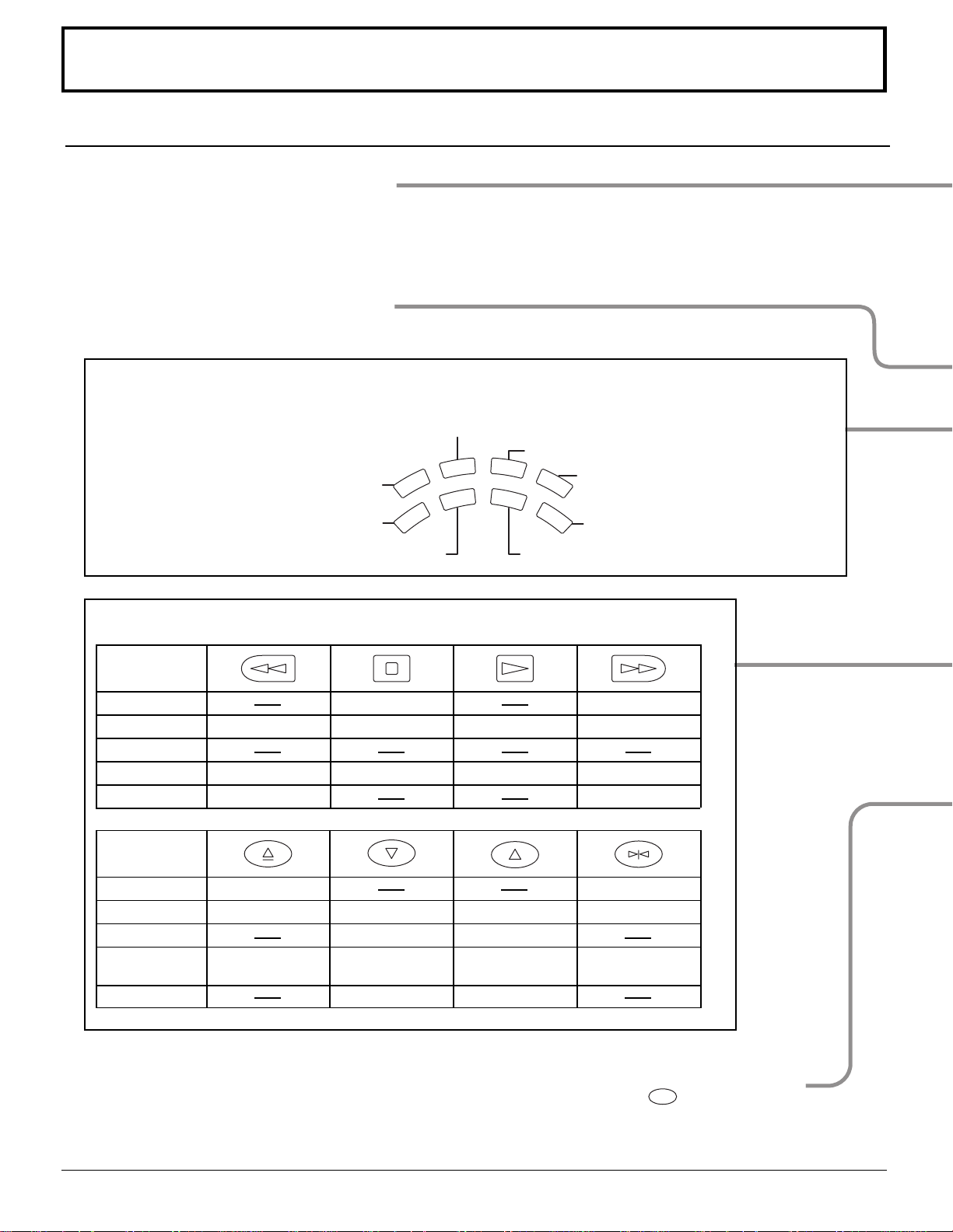
Important Safety Instructions
WARNING
RISK OF ELECTRIC SHOCK
DO NOT OPEN
WARNING: To reduce the risk of electric shock do not remove cover or back. No
user-serviceable parts inside. Refer servicing to qualified service personnel.
The lightning flash with
arrow-head within a triangle
is intended to tell the user
that parts inside the product
are a risk of electric shock to
persons.
The exclamation point within
a triangle is intended to tell
the user that important
operating and servicing
instructions are in the papers
with the appliance.
The pictorial representation
of a hot surface within a
triangle is intended to tell the
user that parts inside the
product are a risk of burns
to persons.
Note to CATV System Installer: This reminder is provided to direct the CATV system installer’s attention to Article
820–40 of the NEC that provides guidelines for proper grounding and, in particular, specifies that the cable ground shall be
connected to the grounding system of the building, as close to the point of cable entry as practical.
Important Safety Instructions For Projection TV
1. Read and apply the operating instructions provided with your projection TV.
2. Read all of the instructions given here and retain them for later use.
3. Follow all warnings and instructions marked on the projection TV.
4. Unplug this projection TV from the wall outlet before cleaning. Do not use liquid or aerosol cleaners. Use a damp cloth
for cleaning.
5.
Do not use attachments / accessories not recommended by the projection TV manufacturer as they may cause hazards.
6. Do not use this projection TV near water. For example: Avoid placing it near a bathtub, washbowl, kitchen sink, or
laundry tub, in a wet basement, or near a swimming pool, etc.
7. Do not place this projection TV on an unstable cart, stand or table. The projection TV may fall, causing serious injury to
a child or adult, and serious damage to the appliance. Use only with a cart or stand recommended
by the manufacturer, or sold with the projection TV.
7A. An appliance and cart combination shall be moved with care. Quick stops, excessive force, and
uneven surfaces may cause the appliance and cart combination to overturn.
8. Slots and openings in the cabinet and the back or bottom are provided for ventilation, and to insure reliable operation
of the projection TV and to protect it from overheating. These openings must not be blocked or covered. There shall be
at least 10 cm of space from these openings. The openings shall never be blocked by placing the projection TV on a
bed, sofa, rug or other similar surface. This projection TV shall never be placed near or over a radiator or heat register.
This projection TV shall not be placed in a built-in installation such as a bookcase unless proper ventilation is provided.
9. Operate only from the type of power source indicated on the marking label. If you are not sure of the type of power
supplied to your home consult your television
dealer or local power company.
10. This projection TV is equipped with a polarized
alternating-current line plug (a plug having one
blade wider than the other). This plug will fit into
the power outlet only one way. This is a safety
feature. If you are unable to insert the plug fully
into the outlet, try reversing the plug. If the plug
should still fail to fit, contact your electrician to
replace your obsolete outlet. Do not defeat the
safety purpose of the polarized plug.
11. Do not allow anything to rest and to pinch on the
power cord. Do not locate this projection TV
where the cord will be abused by persons
walking on it.
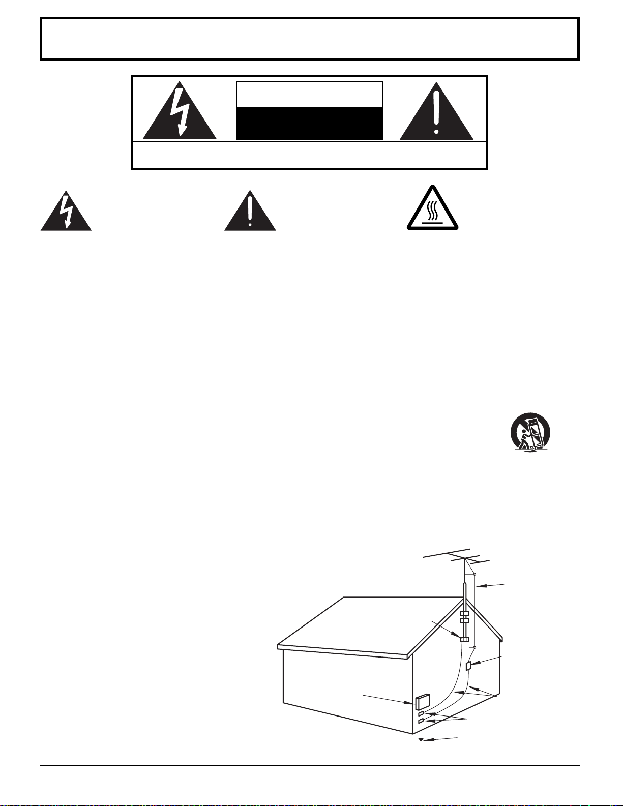
EXAMPLE OF ANTENNA GROUNDING AS
PER (NEC) NATIONAL ELECTRICAL CODE
GROUND
CLAMP
ELECTRIC
SERVICE
EQUIPMENT
ANTENNA
LEAD-IN WIRE
ANTENNA
DISCHARGE UNIT
(NEC SECTION 810-20)
GROUNDING CONDUCTORS
(NEC SECTION 810-20)
GROUND CLAMPS
POWER SERVICE GROUNDING
ELECTRODE SYSTEM
(NEC ART 250, PART H)
2

Important Safety Instructions
12. Do not overload wall outlets and extension cords as this can result in fire or electric shock.
13. Never push objects of any kind into this projection TV through cabinet slots as they may touch dangerous voltage
points or short out parts that could result in a fire or electric shock. Never spill liquid of any kind on the projection TV.
14. If an outside antenna is connected to the television equipment, be sure the antenna system is grounded so as to
provide some protection against voltage surges and built up static charges. In the U.S.Selection 810 of the National
Electrical Code provides information with respect to proper grounding of the mast and supporting structure, grounding
of the lead-in wire to an antenna discharge unit, size of grounding conductors, location of antenna-discharge unit,
connection to grounding electrodes, and requirements for the grounding electrode. See Figure.
15. For added protection for this projection TV during a lightning storm, or when it is left unattended and unused for long
periods of time, unplug it from the wall outlet and disconnect the antenna. This will prevent damage to the receiver due
to lightning and power-line surges.
16. An outside antenna system shall not be located in the vicinity of overhead power lines or other electric light or power
circuits, or where it can fall into such power lines or circuits. When installing an outside antenna system extreme care
shall be taken to keep from touching such power lines or circuits as contact with them might be fatal.
17. Unplug this projection TV from the wall outlet, and refer servicing to qualified service personnel under the following
conditions:
a. When the power cord or plug is damaged or frayed.
b. If liquid has been spilled into the projection TV.
c. If the projection TV has been exposed to rain or water.
d. If the projection TV does not operate normally by follow the operating instructions. Adjust only those controls that are
covered by the operating instructions as improper adjustment of other controls may result in damage and will often
require extensive work by a qualified technician to restore the projection TV to normal operation.
e. If the projection TV has been dropped or the cabinet has been damaged.
f. When the projection TV exhibits a distinct change in performance - this indicates a need for service.
18. Do not attempt to service this projection TV yourself as opening or removing covers may expose you to dangerous
voltage or other hazards. Refer all servicing to qualified service personnel.
19. When replacement parts are required, be sure the service technician has used replacement parts specified by the
manufacturer that have the same characteristics as the original part. Unauthorized substitutions may result in fire,
electric shock, or other hazards.
20. Upon completion of any service or repairs to this projection TV, ask the service technician to perform routine safety
checks to determine that the projection TV is in safe operating condition.
21. WARNING: To prevent fire or shock hazard, do not expose this appliance to rain or moisture.
22. WARNING: Because the temperature of the lamp unit is elevated immediately after its use, a direct touch to it may
cause burns. After the lamp has cooled enough, replace the lamp unit.
23. CAUTION: TO PREVENT ELECTRIC SHOCK DO NOT USE THIS (POLARIZED) PLUG WITH A RECEPTACLE OR
OTHER OUTLET UNLESS THE BLADES CAN BE FULLY INSERTED TO PREVENT BLADE EXPOSURE.
24. CAUTION: This TV set for use only with TV-stand (Model: TY-S52DL10)
Use with other stand is capable of resulting in instability causing possible injury.
NOTE: This equipment is designed to operate in the U.S.A..
3

Dear Panasonic Customer
Welcome to the Panasonic family of customers. We hope that you will have many years of enjoyment
from your new projection television set.
To obtain maximum benefit from your set, please read these Instructions before making any adjustments,
and retain them for future reference.
Retain your purchase receipt also, and note down serial number of your set in the space provided on
the rear cover of these instructions.
Visit our Panasonic Web Site for USA : www.panasonic.com
For assistance, please call : 1-888-VIEW PTV(843-9788)
or send e-mail to : consumerproducts@panasonic.com
or visit us at www.panasonic.com (USA)
For assistance, please call : 787-750-4300
or visit us at www.panasonic.com (Puerto Rico)
Trademarks
DLP are registered trademark of Texas Instruments.
•
Certain audio features of this product are manufactured under a license from Desper Products, Inc. Spatializer® and the circle-in-
•
square device are trademarks owned by Desper Products, Inc.
VGA is a trademark of International Business Machines Corporation.
•
Macintosh is a registered trademark of Apple Computer, USA.
•
S-VGA is a registered trademark of the Video Electronics Standard Association.
•
Even if no special notation has been made of company or product trademarks, these trademarks have been fully respected.
FCC STATEMENT:
NOTE: This equipment has been tested and found to comply with the limits for a Class B digital device, pursuant to Part 15 of the FCC
Rules. These limits are designed to provide reasonable protection against harmful interference in a residential installation. This
equipment generates, uses and can radiate radio frequency energy and, if not installed and used in accordance with the
instructions, may cause harmful interference to radio communications. However, there is no guarantee that interference will not
occur in a particular installation. If this equipment does cause harmful interference to radio or television reception, which can be
determined by turning the equipment off and on, the user is encouraged to try to correct the interference by one or more of the
following measures:
Reorient or relocate the receiving antenna.
•
Increase the separation between the equipment and receiver.
•
Connect the equipment into an outlet on a circuit different from that to which the receiver is connected.
•
Consult the dealer or an experienced radio / TV technician for help.
•
FCC CAUTION:
To assure continued compliance and prevent undesirable interference, use only the provided shielded VGA cable with 2 ferrite cores
(Part# TSXF147) while connecting the Projection TV to a computer. Any changes or modifications not expressly approved by the party
responsible for compliance could void the user’s authority to operate this equipment.
Pursuant to 47CFR, Part 15.21 of the FCC rules, any changes or modifications to this projection TV not expressly approved by
Matsushita Electric Corporation of America could cause harmful interference and would void the user’s authority to operate
this device.
Responsible Party:
This device complies with Part 15 of the FCC Rules. Operation is subject to the following two conditions: (1) This device may not cause
harmful interference, and (2) this device must accept any interference received, including interference that may cause undesired operation.
FCC Declaration of Conformity
PT-52DL10
Matsushita Electric Corporation of America
One Panasonic Way Secaucus, NJ 07094
1-800-528-8601
4

Table of Contents
Important Safety Instructions ................................ 2
Installation ............................................................... 6
Receiver Location .................................................. 6
Optional External Equipment ................................. 6
AC Power Supply Cord .......................................... 6
Safety Precaution...................................................6
Remote Control Battery Installation ....................... 7
Connecting the Antenna Cable to the RF In Termina
Antenna / Cable Connection .................................. 8
How to connect the “1, 2, 3, 4” Input Terminals ..... 11
How to connect the COMPONENT VIDEO Input Terminals ......
How to connect the AV Prog. Out Terminals .......... 13
How to connect the PC Input Terminals ................. 14
Analog RGB signals that can be input ................... 15
Location of Controls ............................................... 16
Illuminated Remote Control ...................................16
Controls and Terminals on the projection TV ......... 18
Power ON / OFF ....................................................... 20
Connecting the Plug to the Wall Outlet .................. 20
Turning the Power ON and OFF ............................ 20
Flow Chart of Main menu ....................................... 22
Tuning channels (Automatic channel programming) .......
Tuning channels (Manual channel programming) ...........
ASPECT Controls .................................................... 28
VHF, UHF and CATV ................................................30
Cable TV ................................................................... 31
Searching for the desired channel (Channel search) ....
Playing a VCR or other peripheral equipment ..... 33
Playing games in game mode................................ 34
l .... 8
12
24
26
32
Recall / Mute ............................................................ 35
Split screen .............................................................. 36
Adjusting screen position and size ....................... 38
Audio Adjustments ................................................. 40
Picture Adjustments ............................................... 42
Playing special video software .............................. 45
Closed Captions ...................................................... 46
Lock Feature ............................................................ 48
Customizing the VIDEO INPUT labels ................... 51
Selecting STEREO / SAP / MONO .......................... 53
Using the off-timer .................................................. 54
Video game player to VIDEO INPUT ...................... 55
Optimizing display for DVC recording mode
(DVC PLAYBACK MODE) ..................................... 56
Turning OFF digital comb filter .............................. 57
Automatically changing screen size
for VIDEO INPUT modes...................................... 58
Setting when 480p signals (sequential scan) are
input through COMPONENT VIDEO INPUT ....... 59
CLOCK ..................................................................... 60
Switching languages for display ........................... 61
Replacing the lamp unit ......................................... 62
Operating peripheral equipment using
the remote control ...............................................63
Troubleshooting ...................................................... 71
Cleaning ................................................................... 72
Specifications .......................................................... 73
5
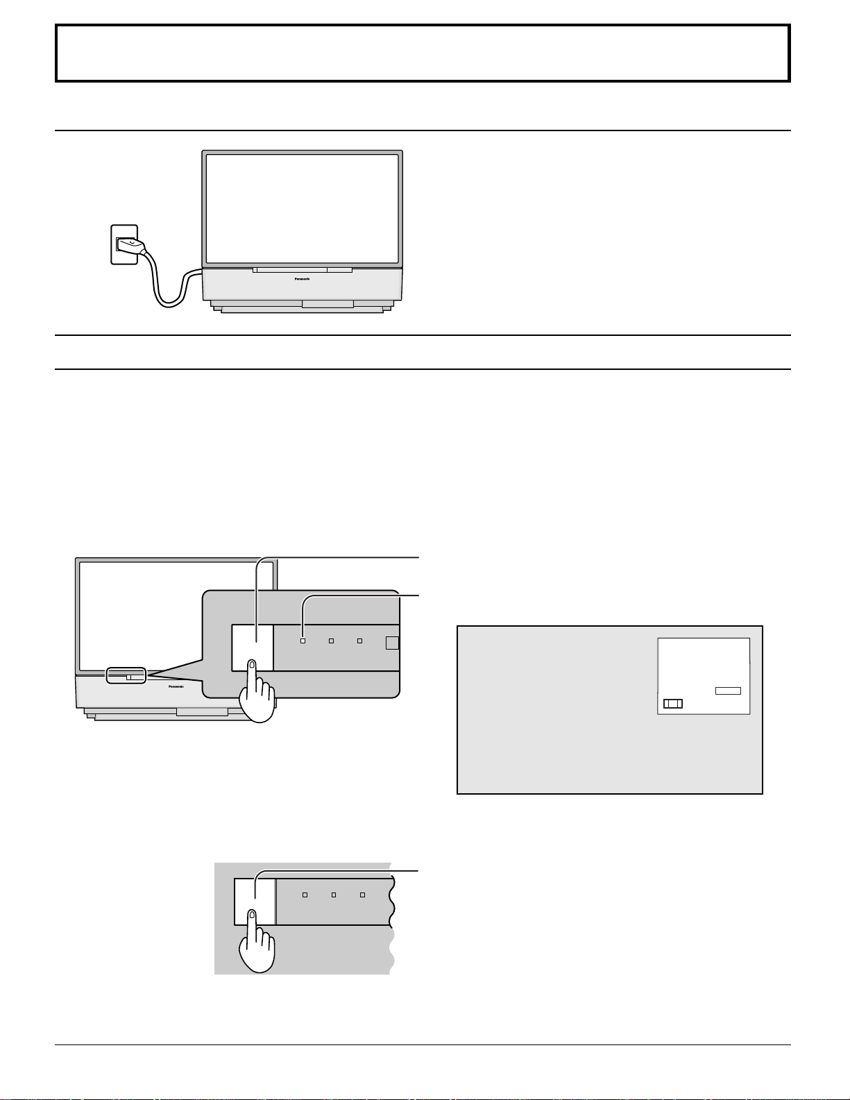
Installation
Receiver Location
This unit is intended to be used with an optional stand or entertainment center. Consult your dealer for available options.
Locate for comfortable viewing. Avoid placing where sunlight or other bright light (including reflections) will fall on the
screen.
Use of some types of fluorescent lighting can reduce remote control transmitter range.
Adequate ventilation is essential to prevent internal component failure. Keep away from areas of excessive heat or
moisture.
Optional External Equipment
The Video / Audio connection between components can be made with shielded video and audio cables. For best
performance, video cables should utilize 75 Ω coaxial shielded cables. Cables are available from your dealer or electronic
supply house.
Before you purchase any cables, be sure you know what type of output and input connectors your various components
require. Also determine the length of cable you’ll need.
AC Power Supply Cord
CAUTION: To prevent electric shock, match wide blade of plug to wide slot of AC outlet and fully insert. Do not use this
(polarized) plug with a receptacle or other outlet unless the blade can be fully inserted to prevent blade
exposure.
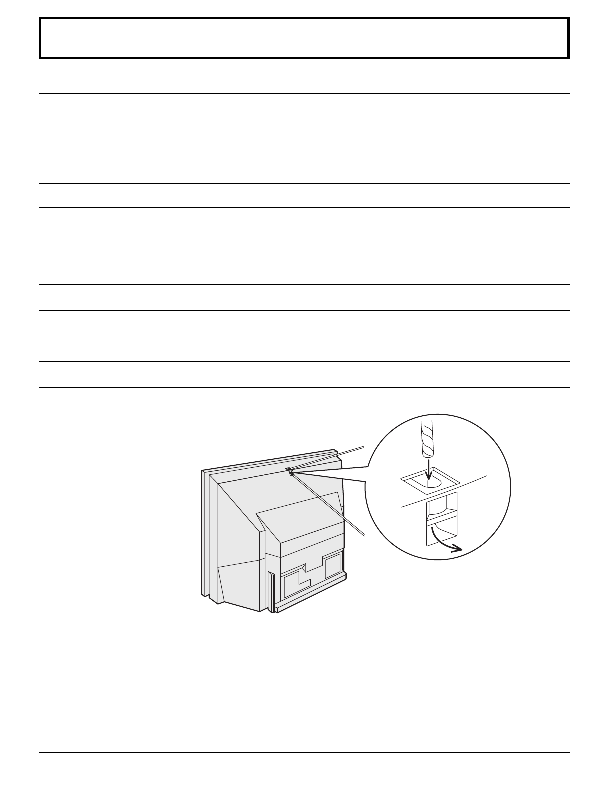
Safety Precaution
Please take safety precautions to prevent the unit
from falling over.
The unit may fall over during earthquakes, or if
someone stands on or shakes the projection TV.
Fixing to a wall
Use a strong rope or a chain (not included)
to fasten the projection TV firmly to a strong
support such as a wall or pillar.
6
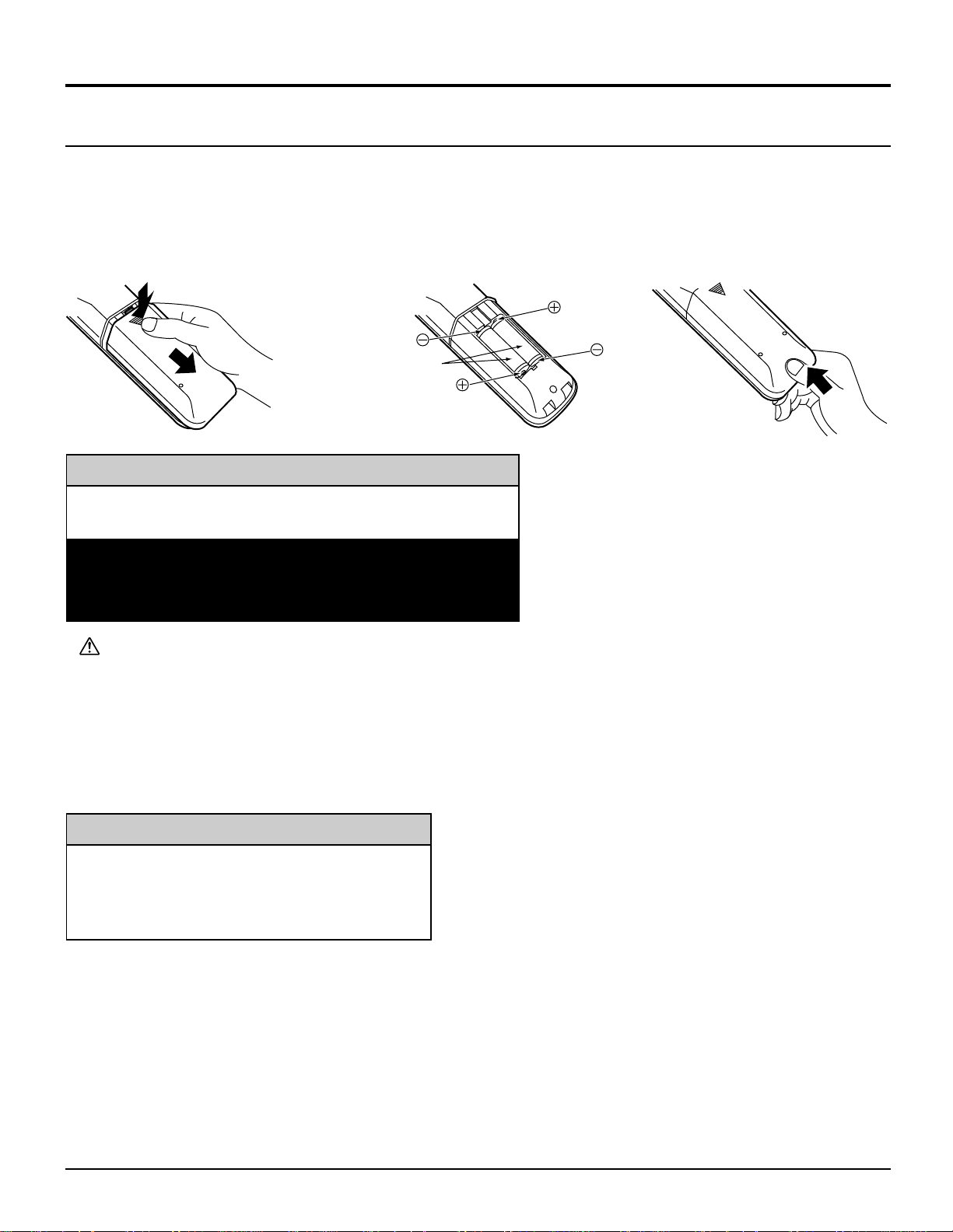
Remote Control Battery Installation
Requires two AA batteries (supplied).
Installation
1. Turn the Transmitter face down.
Remove top cover by pressing
down on marking and sliding cover
off in the direction indicated.
2. Install the batteries as shown in
the battery compartment. (Polarity
+ or – must match the markings in
the compartment).
Two AA size
3. Replace the cover and slide in
reverse until the lock snaps.
Helpful Hint:
For frequent remote control users, replace old
batteries with Alkaline batteries for longer life.
Note: In order to maximize the life of the batteries, the
lighted buttons on the Remote Control can be turned OFF
and ON by pressing R-TUNE and RECALL at the same
time.
Precaution on battery use
Incorrect installation can cause battery leakage and corrosion that will damage the remote control transmitter.
Observe the following precautions:
1. Batteries should always be replaced as a pair. Always use new batteries when replacing the old set.
2. Do not combine a used battery with a new one.
3. Do not mix battery types (example: “Zinc Carbon” with “Alkaline”).
4. Do not attempt to charge, short-circuit, disassemble, heat or burn used batteries.
5. Battery replacement is necessary when the remote control acts sporadically or stops operating the projection TV set.
Helpful Hint:
Whenever you remove the batteries, you may
need to reset the remote control infrared
codes. We recommend that you record the code
on page 64, prior to setting up the remote.
7
Installation
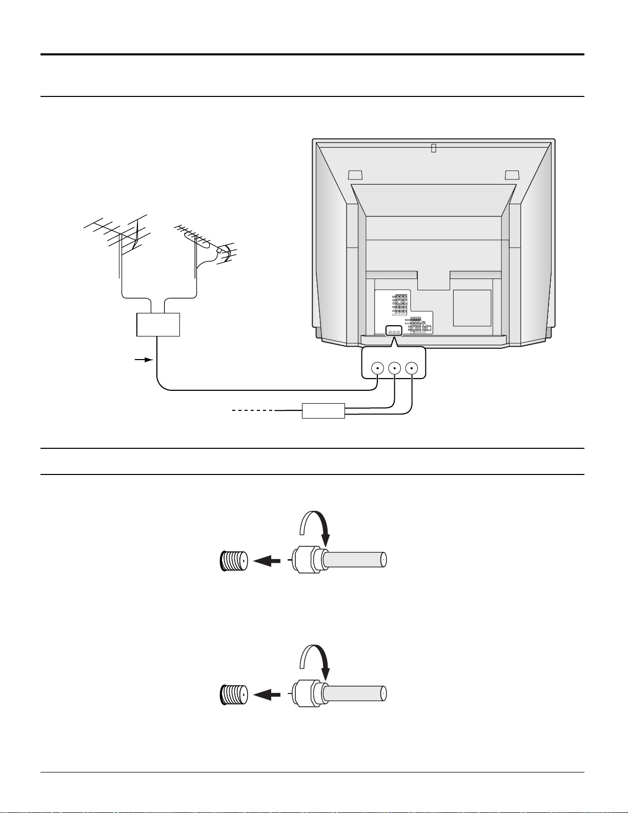
Connecting the Antenna Cable to the RF In Terminal
Antenna Connection - For proper reception of VHF / UHF channels, an external antenna is required. For best reception
an outdoor antenna is recommended. Antenna Mode must be set to projection TV.
VHF Antenna
UHF Antenna
Mixer
75 Ω
RF In Terminal
Coaxial Cable
Coaxial Antenna Plug
Cable Box
Antenna / Cable Connection
Incoming Cable From Home Antenna (75 Ω)
Y
VIDEO
P
B
R
P
L
AUDIO
R
213
INPUT
COMPONENT VIDEO
S-VIDEO
VIDEO
L
AUDIO
ANT1 ANT2
SPLIT
R
OUT
ANT1 ANT2
SPLIT
OUT
L
TO
AUDIO
AMP
R
213
PROG
INPUT
OUT
VHF / UHF
on Back of Set
Cable Connection - For reception of cable channels (01 - 125) connect the cable supplied by your local cable company.
Antenna Mode must be set to CABLE. (Refer to Antenna Mode section.)
Incoming 75 Ω Cable (From Cable Company)
VHF / UHF
on Back of Set
Note:
Certain cable systems offset some channels to reduce interference or have Premium (scrambled) channels. A cable
converter box is required for proper reception. Check with your local Cable company for its compatibility requirements.
8
Installation
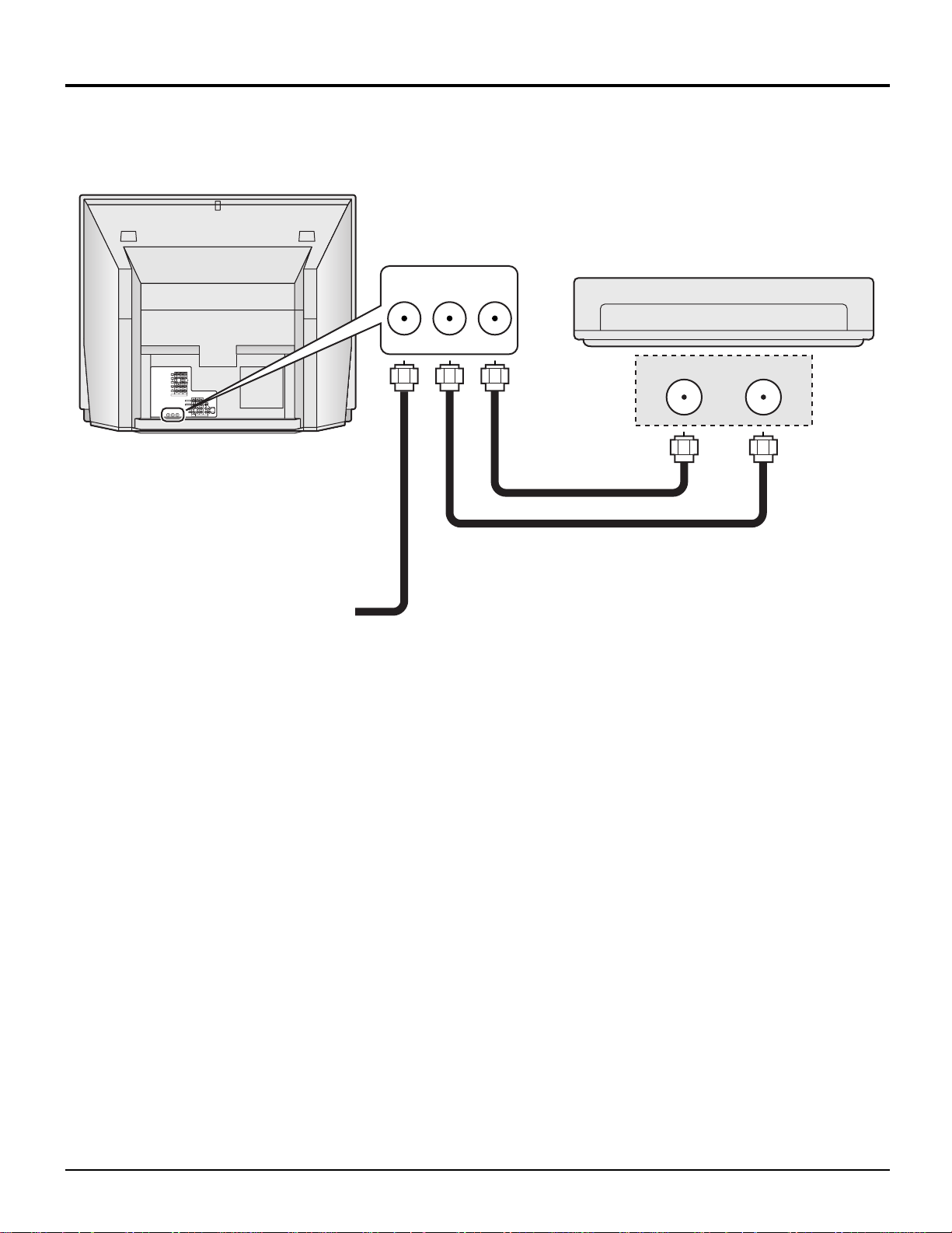
Antenna Connection (Cable Box, no VCR)
Use this configuration when connecting the projection TV to a cable TV system using a Cable Box.
ANTENNA TERMINALS
ON THE BACK OF THE
PROJECTION TV
ANT1 ANT2
SPLIT
OUT
CABLE BOX
Y
VIDEO
P
B
R
P
L
AUDIO
R
213
INPUT
COMPONENT VIDEO
S-VIDEO
VIDEO
L
L
TO
AUDIO
AUDIO
ANT1 ANT2
SPLIT
AMP
OUT
R
R
213
PROG
INPUT
OUT
Connect the cable from the antenna
or cable system to the ANT1
terminal on the back of the
projection TV.
Incoming Cable from Antenna
or Cable TV System
TERMINAL ON
THE BACK OF
THE CABLE BOX
INPUTOUTPUT
Notes:
When the antenna cable is connected to the projection TV antenna terminal via a cable box or VCR, set the TV channel
•
to CH3 or CH4 cable, after select ANT2 in the PROGRAM CHANNELS. (See page 24, 26) This does not apply when
signal is input from VIDEO INPUT.
To use special features such as Favorite Channel Captions, ANT1 must be selected in the PROGRAM CHANNELS.
•
(See page 24, 26)
9
Installation
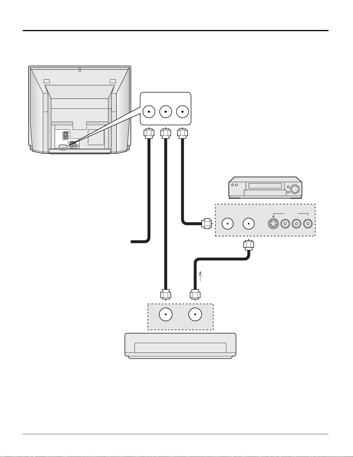
Antenna Connection (Cable Box, and VCR)
Use this configuration when connecting the projection TV to a cable TV system using a Cable Box and VCR.
ANTENNA TERMINALS
ON THE BACK OF THE
PROJECTION TV
ANT1 ANT2
SPLIT
OUT
Y
VIDEO
P
B
R
P
L
AUDIO
R
213
INPUT
COMPONENT VIDEO
S-VIDEO
VIDEO
L
L
TO
AUDIO
AUDIO
ANT1 ANT2
SPLIT
AMP
OUT
R
R
213
PROG
INPUT
OUT
Connect the cable from the antenna
or cable system to the ANT1
terminal on the back of the
projection TV.
Connect the cable from the
Output terminal on the back
of the Cable Box to the
Antenna input terminal on the
back of the VCR.
VCR
Incoming Cable from Antenna
or Cable TV System
Connect the cable from the
antenna or cable system to
the Input terminal on the
back of the CABLE BOX.
TERMINAL ON
THE BACK OF
THE CABLE BOX
INPUT OUTPUT
CABLE BOX
OUTPUT INPUT
TO VCR
S-VIDEO
OUTPUT
VIDEO
L-AUDIO-R
Notes:
When the antenna cable is connected to the projection TV antenna terminal via a cable box or VCR, set the TV channel
•
to CH3 or CH4 cable, after select ANT2 in the PROGRAM CHANNELS. (See page 24, 26) This does not apply when
signal is input from VIDEO INPUT.
To use special features such as Favorite Channel Captions, ANT1 must be selected in the PROGRAM CHANNELS.
•
(See page 24, 26)
10
Installation
TO
AUDIO
AMP
L
R
AUDIO
VIDEO
S-VIDEO
L
R
INPUT
PROG
OUT
213
TO
AUDIO
AMP
L
R
AUDIO
VIDEO
S-VIDEO
L
R
INPUT
PROG
OUT
213
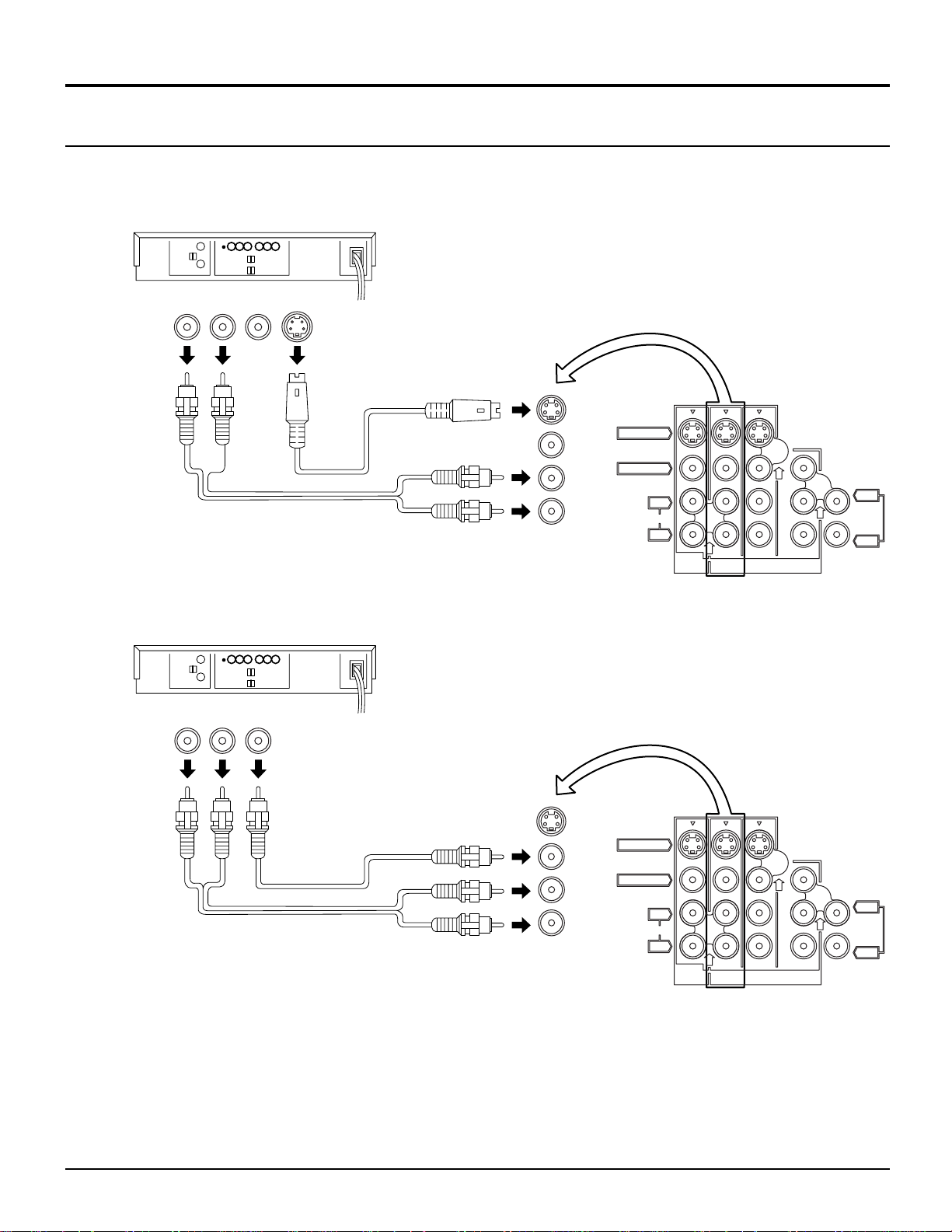
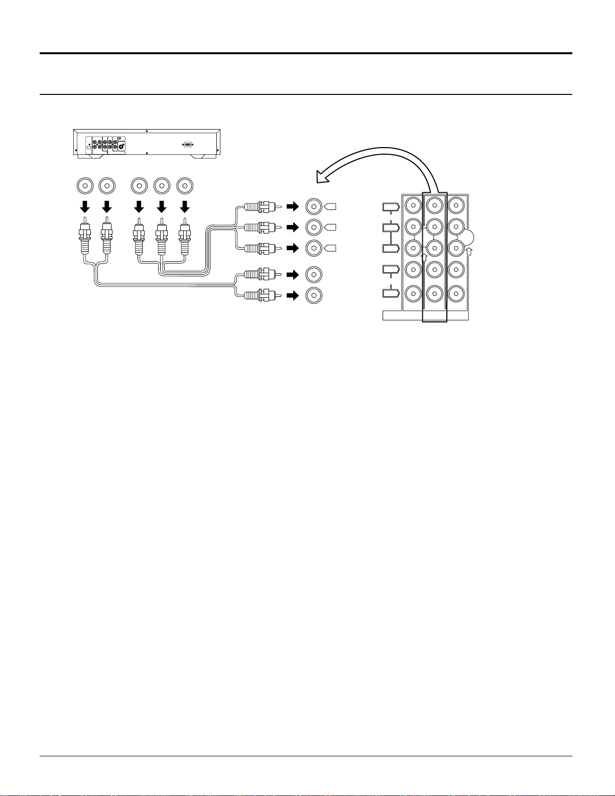
How to connect the “1, 2, 3, 4” Input Terminals
Connects VCRs and other peripheral equipment
(Super-VHS VCR)
Audio
OUT
RL
Video
OUT
S-Video
OUT
VIDEO
AUDIO
Similar connections are available at the INPUT 1, 2, 4 input terminals.
(VHS VCR)
Audio
OUT
R
Video
OUT
L
VIDEO
AUDIO
Similar connections are available at the INPUT 1, 2, 3, 4 input terminals.
Notes:
Similar connections are available at the INPUT 1, 2, 3, 4 input terminals.
•
Input 4 is located on the front of the unit.
Select the desired VIDEO input position by pushing the TV/VIDEO button. (See page 33)
When connecting video cables, priority is given to the S-Video cable when the S-Video input terminal and the video input
•
terminal are connected at the same time.
11
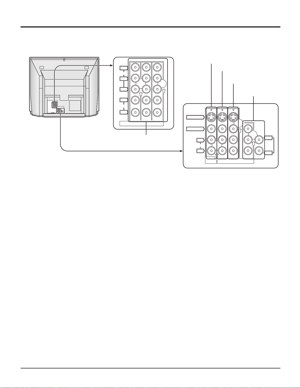
Installation
How to connect the COMPONENT VIDEO Input Terminals
DVD Player
Audio
OUT
DVD(Y/PB/PR) OUT
P
B
LR
R
YP
DVD(Y/PB/PR)
AUDIO
Y
B
P
P
R
Y
VIDEO
P
P
L
AUDIO
R
B
R
213
COMPONENT VIDEO
INPUT
Note:
Similar connections are available at the COMPONENT VIDEO Input 1, 2, 3 Terminals.
12
Installation
How to connect the AV Prog. Out Terminals
The “Prog. Out” Terminals output the same signals as the main picture on the projection TV screen and sound from the
speaker at that time, e.g. TV programs or signals from INPUT 1, 2, 3, 4 terminals.
Recording Equipment
(VHS VCR)
Audio
IN
L
R
Video
IN
S-Video
IN
VIDEO
AUDIO
S-VIDEO Cable
S-VIDEO
VIDEO
AUDIO
L
R
PROG
OUT
213
INPUT
L
TO
AUDIO
AMP
R
Notes:
Never connect the VIDEO IN and Prog. OUT terminals to the same video recorder, as this could cause incorrect operation.
•
The monitor output emits the main picture’s normal video and audio signals.
•
Even if the television is in picture-out-picture condition, Prog. OUT terminals output the same signals as main picture on
•
the screen and sound from speaker. Sub picture including, still, channel search, etc. will not be output at the PROG. OUT
terminals.
Signal (Y, PB, PR) is not output at the Prog. OUT terminals.
•
To AUDIO AMP terminals cannot be used directly with external speakers.
•
13
Installation
1
67839
45
10
15 14 13 12 11
2
How to connect the PC Input Terminals
COMPUTER
Conversion adapter (if necessary)
Signal Names for D-SUB 15P Connector
Pin No.
1
2
3
Pin Layout for PC Input
Terminal
4
5
D-SUB 15P
RGB
PC cable
(supplied)
TSXF147 (1.5 m)
Audio
Connect a cable which matches
the audio output terminal on the computer.
Signal Name
R
G
B
GND (Ground)
GND (Ground)
Pin No.
6
7
8
9
10
Signal Name
GND (Ground)
GND (Ground)
GND (Ground)
NC (not connected)
GND (Ground)
PC INPUT
2 × RCA plug
Pin No.
11
12
13
14
15
INPUT 4
VIDEO
L-AUDIO-R
Signal Name
GND (Ground)
SDA
HD / SYNC
VD
SCL
Notes:
(1) The PC input terminals are DDC1/2B-compatible. If the computer being connected is not DDC1/2B-compatible, you will
need to make setting changes at the computer at the time of connection.
(2) Some PC models cannot be connected to the set.
(3) An adapter is required to use the PC cable (D-SUB 15P) to connect a Macintosh computer to the set.
(4) There is no need to use an adapter for computers with PC / AT compatible D-SUB 15P terminal.
(5) The computer shown in the illustration is for example purposes only.
(6) Additional equipment and cables shown are not supplied with this set.
(7) The picture will become dark if a PC signal with a vertical scanning frequency of 62 Hz is input. To obtain the optimum
picture quality with the projection TV, a vertical scanning frequency of 60 Hz is recommended.
(8) Do not set the horizontal and vertical scanning frequencies for PC signals which are above or below the specified
frequency range.
14
Installation
Analog RGB signals that can be input
The table below lists the different types of analog RGB signals that can be input.
If a signal which differs greatly from any of the types listed below is input, the picture image may not be displayed correctly,
or black background may displayed.
Display mode name
VGA400
VGA480
SVGA
XGA
No. of dots (H × V)
640 × 400
640 × 400
640 × 480
640 × 480
640 × 480
640 × 480
640 × 480
800 × 600
800 × 600
800 × 600
800 × 600
800 × 600
800 × 600
1024 × 768
1024 × 768
Horizontal scanning
frequency (kHz)
24.8
31.5
31.5
35.0
37.9
37.5
43.3
32.1
35.2
37.9
48.1
46.9
53.7
48.4
56.5
Vertical scanning
frequency (Hz)
56.4
70.1
59.9
66.7
72.8
75.0
85.0
51.0
56.3
60.3
72.1
75.0
85.1
60.0
70.1
1024 × 768
MAC16
Note:
The number of dots for this set is 800 × 600 for NORMAL display. Number of dots other than 800 × 600 in the above data,
will be converted to 800 × 600 (with the exception of MAC 16, which will be displayed in 832 × 624 dots).
832 × 624
60.0
49.7
75.0
74.6
15
Location of Controls
Illuminated Remote Control
Power button
Press to turn the projection TV ON or OFF. (See page 21)
Note:
The TV’s power cord must first be plugged into the wall outlet and then turned on at the
POWER switch (standby mode).
MUTE button
Push this button to mute the sound. (See page 35)
Mode Selection buttons
Selects the operation mode for the remote control. (See page 63)
Digital Video Disk Mode Selection for Remote Control
AUX
CBL
VCR Mode Selection for Remote Control
TV Mode Selection for Remote Control
Digital TV Mode Selection for Remote Control
DVD
VCR
DTV
TV
Aux Mode Selection for Remote Control
Receiver / Amplifier Mode Selection
RCVR
for Remote Control
DBS
Digital Broadcasting Satellite for
Remote Control
Cable TV Mode Selection for Remote Control
Operating of other Device
Buttons
TV
VCR
CABLE / DBS
DVD / LD / CD
RCVR
Buttons
TV
VCR
CABLE / DBS
DVD / LD / CD
RCVR
REW
Skip Search REW
Surround –
Split Freeze
TV/VCR switch
Open / Close
Split Search
STOP
STOP
Channel down
Channel down
Slow - / LD-sideB
/ Random
Center –
PLAY
PLAY
Channel up
Channel up
Slow + / LD-sideA
/ Repeat
Center +
Split ON / OFF
FF
Skip Search FF
Surround +
Split Swap
Pause
Still / Pause
16
R-TUNE
R-TUNE button
Switches to previously view
to channel or video mode.
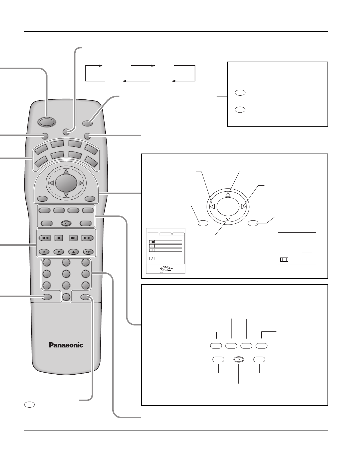
ASPECT button
Change of screen size. (See page 28)
Location of Controls
AUX
CBL
GAME
PLAY
LIGHT
RCVR
INFO/RECALL
RH-SPLIT
GUIDE
SPLIT
FF
SWAP
PAUSE
POWER
MUTE TV/VIDEO
VCR
TV
VOL VOL
MENU
AV-ADJ
REW
FREEZE
TV/VCR
OPEN/CLOSE STILL
DVD
DTV
NORMAL
EXIT
SEARCH
VCR/DBS CHANNEL
ASPECT
CH
ACTION
CH
VCR REC
STOP
SLOW
123
456
NORMAL JUST
FULL ZOOM
Lights the remote control buttons
The selected button blinks when lit.
DBS
Turning ON and OFF the remote
control illumination
R-TUNE
Remote control illumination
can be turned ON and OFF
+
INFO/RECALL
by pressing the INFO/
RECALL button while
pressing the
R-TUNE button.
TV/VIDEO buttons
This input mode changes each time this button is pressed. (See page 33)
Changes to the next channel up
Moves cursor upward during menu mode.
Reduces volume
Moves cursor to the
left during menu
mode.
CH
Increase volume
Moves cursor to the
right during menu
Displays menu
VOL VOL
ACTION
mode.
Press the Menu
button to display
the Menu screen.
MENU
ADJUST
PICTURE ADJUST
POSITION/SIZE
CLOCK
AUDIO ADJUST
PAGE
CUSTOM
PICTURE
AUDIO
ACTION
EXIT
SET UP
SELECT
MENU
CH
INFO/RECALL
Changes to the next
channel down
Moves cursor downward
during menu mode.
The screen below
is displayed for 10
seconds.
CH123
STEREO
SAP
MONO
NORMAL
789
R-TUNE PROG
PROG
PROG button
0
NORMALIZATION button
Each setting in the MENU
screen is reset to its standard
values. (PICTURE, AUDIO,
POSITION / SIZE / CLOCK)
AV ADJUSTMENT
button
AV-adjustments are
displayed.
AV-ADJ
(See page 43, 44)
Returns to normal
viewing from the
MENU screen.
Previous before item
VCR Record button
NORMAL
EXIT
GAME button
(See page 34)
GAME
VCR REC
RH-SPLIT
GUIDE
RH-SPLIT button
Operates the right
screen. (See page
37)
GUIDE button
for DBS.
in MENU.
Direct program number
selection buttons
17
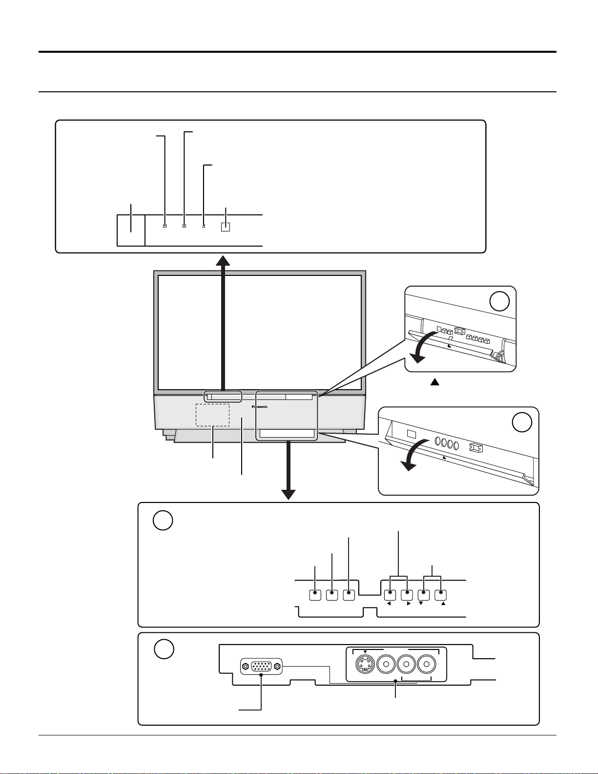
Location of Controls
Controls and Terminals on the projection TV
< FRONT >
POWER INDICATOR
R-STAND BY
G-POWER ON
(see page 20, 21)
POWER SWITCH
(see page 20)
POWER
R-STANDBY
G-POWER ON
LAMP
This indicator lights up when there is a malfunction with the
lamp unit (see page 62, 71)
TEMP
This indicator lights up when there is an abnormal temperature
in the unit (see page 71)
Remote Control Sensor (see page 21)
LAMP TEMP
Press the
front cover to open.
A
Open
mark on the center of the
Lamp unit (see page 62)
Speaker panel
A
Input mode selection buttons (see page 33)
Action button (see page 23)
Menu button (see page 22)
B
PC Input terminal
PC INPUT
MENU ACTION
B
Open
Volume up(+) / down(–) buttons
(see page 22, 30)
Channel up / down
buttons (see page 23, 30)
VOLUME
INPUT 4
S-VIDEO VIDEO
Input4 terminals
Video camera and TV game cable terminal
CHANNELTV/VIDEO
L-AUDIO-R
18
< REAR >
Monitor out terminals (see page 13)
Y
VIDEO
PB
P
R
Input1 terminals (see page 11)
Input2 terminals
(see page 13)
Input3 terminals
(see page 13)
Y
VIDEO
PB
P
R
L
AUDIO
R
213
INPUT
COMPONENTVIDEO
S-VIDEO
VIDEO
L
L
TO
AUDIO
AUDIO
ANT1 ANT2SPLIT
AMP
OUT
R
R
213
PROG
INPUT
OUT
L
AUDIO
R
213
COMPONENT VIDEO
INPUT
Component signal input
(see page 12)
S-VIDEO
VIDEO
AUDIO
L
R
PROG
OUT
213
INPUT
L
TO
AUDIO
AMP
R
19
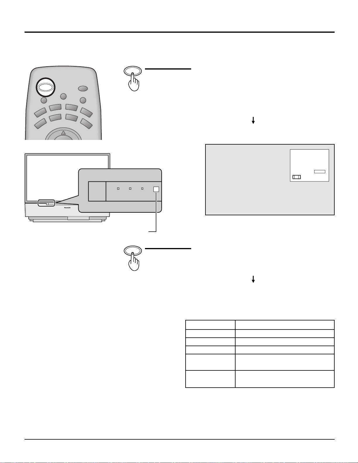
Power ON / OFF
Connecting the Plug to the Wall Outlet
Turning the Power ON and OFF
Always be sure to follow the procedure given below to turn the projection TV power ON and OFF.
The lamp cooling fan will continue to operate for approximately 90 seconds after the power is turned off by the remote control.
•
At the same time, the power indicator will blink Orange.
Normally, use the remote control to turn the power OFF (turning the picture OFF).
Do not disconnect the power cord from the power outlet or do not open any circuit breakers while the cooling
fan is still operating.
Do not disconnect the power cord from the power outlet while in Stand-by mode.
When you want to turn on the power again immediately after turning off the power during the operation of the projection
•
TV, be sure to wait until the cooling fan stops and then turn on the power.
Setting the projection TV to Stand-by, the power indicator will light up red.
Push the Power switch on the projection TV to turn the power
on.
The Power Indicator will become Green and blink
(approximately 10 seconds).
POWER
R-STANDBY
G-POWER ON
POWER
R-STANDBY
G-POWER ON
Note:
When the power is switched off using the POWER switch on the set, the internal cooling fan also stops operating. Therefore,
the lamp is not sufficiently cooled and will take a while for it to turn ON again.
TEMP
LAMP
LAMP TEMP
CH123
STEREO
SAP
MONO
NORMAL
Example: The screen above is display for a while after the
projection TV is turned on. (Setting condition is an
example.)
Push the Power switch on the projection TV to turn the set off.
The Power Indicator will no-illumination.
The Power Indicator will light
Power-OFF ............ Not illuminate
•
Stand-by ................ Red
•
Power-ON .............. Green
•
20
Power (ON / OFF) button
Power ON / OFF
AUX
CBL
LIGHT
RCVR
POWER
MUTE TV/VIDEO
VCR
TV
ASPECT
DVD
DTV
CH
POWER
DBS
POWER
R-STANDBY
G-POWER ON
LAMP TEMP
Remote Control Sensor
Push the Power button to turn the projection TV ON,
from Stand-by mode.
The projection TV must first be switched on at the wall
outlet and the Power switch.
The Power Indicator will blink Green.
Approximately 10 seconds
The Power Indicator will become Green.
CH123
STEREO
SAP
MONO
NORMAL
Example: The screen above is display for a while after
the projection TV is turned on. (Setting
condition is an example.)
POWER
Push the Power button to turn the projection TV to
Stand-by mode.
The Power Indicator will become Orange.
Approximately 90 seconds
The Power Indicator will become Red.
The Power Indicator
LED
No illuminated
Red
Green
Green blink
(approximately 10 seconds after)
Orange blink
Power – OFF (by the remote control)
(approximately 90 seconds after)
Note:
Even when the main power switch (FUNCTION SWITCH) is turned off, and the POWER indicator is not lit, the projection
TV is not completely cut off from the power if the power cable is still plugged in.
ACTION
Power – OFF
Stand – by
Power – ON
Power – ON
21
Flow Chart of Main menu
ACTION TV/VIDEO
MENU VOLUME
CHANNEL
CH
VOL VOL
CH
ACTION
12
If the MENU button is pressed, the
MENU screen will be displayed.
If the MENU button is pressed
once more while the menu screen
is displayed, the MENU screen
will be cleared.
MENU
AUX
CBL
GAME
PLAY
LIGHT
RCVR
DBS
INFO/RECALL
RH-SPLIT
GUIDE
SPLIT
FF
SWAP
PAUSE
The MENU button on the main
body can also be pressed to
display the MENU screen.
MENU VOLUME
ACTION TV/VIDEO
MENU
ADJUST
PICTURE ADJUST
POSITION/SIZE
CLOCK
AUDIO ADJUST
CUSTOM
PICTURE
AUDIO
CHANNEL
SET UP
POWER
MUTE TV/VIDEO
VCR
TV
VOL VOL
MENU
AV-ADJ
FREEZE
TV/VCR
OPEN/CLOSE STILL
EXIT
REW
ASPECT
DVD
DTV
CH
ACTION
CH
NORMAL
VCR REC
SEARCH
STOP
VCR/DBS CHANNEL
SLOW
Select MENU desired by pushing Right
” button or Left “
“
The
Left “
Right “
” button.
” button and
” button
on the
main body can also be
used to select items on
the MENU screen.
MENU
ADJUST
CUSTOM
PICTURE
PICTURE ADJUST
POSITION/SIZE
CLOCK
AUDIO
AUDIO ADJUST
ACTION
SET UP
123
ACTION
PAGE
EXIT
SELECT
456
789
R-TUNE PROG
0
MENU
ADJUST
CUSTOM
CHANNEL SEARCH
SET UP
SLEEP TIMER 0
AUDIO MODE
22
ACTION
MENU
ADJUST
CUSTOM
LANGUAGE
PROGRAM CHANNELS
LOCK
CLOSED CAPTION
VIDEO
SET UP
Flow Chart of Main menu
CLOCK
NORMAL
SELECT
CLOCK PHASE
DOT CLOCK
EXIT
ACTION
0
0
ADJUST
CH
VOL VOL
ACTION
CH
TO PICTURE
ADJUST menu
PICTURE ADJ.
PICTURE MENU
PICTURE
BRIGHTNESS
COLOR
TINT
SHARPNESS
COLOR TEMP
BLACK EXT.
EXIT
30
0
0
0
10
ACTION
NORMAL
DYNAMIC
— +
— +
— +
— +
COOL
OFF ON
SELECT
See page 42
1
MENU VOLUME
The CHANNEL button on the
main body can also be pressed
2
to select items in the MENU
screen.
TO POSITION/
SIZE
POSITION/SIZE
NORMAL
NORMALIZE
See page 38
2
ACTION TV/VIDEO
SIZE
1
1
CHANNEL
TO AUDIO
ADJUST menu
AUDIO ADJ.
AUDIO MENU
BASS
TREBLE
BALANCE
SPATIALIZER
SPEAKERS
CHANGE
6
4
0
EXIT
See page 40
NORMAL
AUTO
— +
— +
— +
OFF ON
OFF ON
SELECT
TO CLOCK
See page 60
When the set is connected to the
•
PC, CLOCK can be adjusted.
LANGUAGE
TO CHANNEL
SEARCH screen
TO LANGUAGE
selection screen
LANGUAGE
ENGLISH
FRAN
CHANGE
EXIT
See page 61
TO SLEEP TIMER
SLEEP TIMER
SLEEP TIMER
See page 32
TO PROGRAM
CHANNELS adjust screen
PROGRAM CHANNELS
AIS
MODE TV CABLE
ANTENNA ANT1 ANT2
AUTO PROGRAM
MANUAL PROGRAM
CHANGE
EXIT
See page 24
ANTENNA switching for
•
PROGRAM CHANNEL is
possible only during TV mode.
adjust screen
CHANGE
EXIT
See page 54
SELECT
TO AUDIO MODE
adjust screen
AUDIO MODE
0
AUDIO MODE
STEREO
TO LOCK
selection screen
LOCK
MOTION PICT. STATUS
TV PARENTAL STATUS
ENTER CODE FIRST
CHANGE
OFF ON
CHANGE SETTING
OFF ON
CHANGE SETTING
— — — —
EXIT
See page 48
SAP
MONO
CHANGE
EXIT
See page 53
TO CLOSED CAPTION
SELECT
selection screen
CLOSED CAPTION
ON MUTE
MODE
CHANGE
EXIT
See page 46
NO
OFF
SELECT
TO VIDEO
adjust screen
VIDEO
VIDEO NR
VIDEO
DVC PLAYBACK MODE
CHANGE
OFF ON
NORMAL FRAME
3D Y/C FILTER
VIDEO
ID-1
VIDEO INPUT LABEL
SCAN MODE
EXIT
TV
GAME
480p COLOR MATRIX
CHANGE
EXIT
CHANGE
PAGE 1 / 3
PAGE 2 / 3
OFF ON
OFF ON
SELECT
GAME
VIDEO 1
SDTV HDTV
SELECT
EXIT
PAGE 3 / 3
SELECT
See page 45, 51, 55 - 59
23
 Loading...