

Panasonic PT-51D31CE, PT-61D31CE Service Manual
ORDER NO. MTNC010420A1
B2
Service Manual
Color Video Projection System
S
m
i
p
l
i
f
i
e
d
Simplified Manual
P6
Panasonic
Models
PT-51D31CE AP821
PT-61D31CE AP821
Chassis
Note: Refer to Technical Guide (P6) for
functional descriptio ns and Bloc k Diag rams .
(MTNC010308G1).
This Simplified Se rvice Manual is issued to add listed model to the Main Ser vice Manual order No. MTNC010 307C1
(PT-51G36E). A full set of schematics, disassembly procedures, and a complete parts list are included in this Simplified
Manual. Please file and use this manual together with Main Service Manual, order No. MTNC010307C1 (PT-51G36E).
“WARNING! This Service Manual is desig ned for expe rienced repa ir technici ans only and is not de signed for u se by the general pub lic.
It does not contain warnings or cautions to advise non-technical individuals of potential dangers in attempting to service a product.
Products powered by electricity should be serviced or repai red only by exp erienced profe ssional techn icians. Any attemp t to
service or repair the product or products dealt with in this Service Manual by anyone else could result in serious injury or death.”
The service technician is required to read and follow the “Safety Precautions” and “Important Safety Notice” in this Manual.
Copyright 2001 by Matsushita Electric Corporation of
America. All rights reserved. Unauthorized copying
and distribution is a violation of law.
Important Safety Notice
Special components are used in this projection television that are important for safety. These components are
identified on the schematic diagram by the symbol and printed in BOLD TYPE on the replacement part list. It is
essential that these c ritical parts be replace d with the manufactur er’s speci fied replacement part to prevent x-ray
radiation, shock, fire or other hazards. Do not modify the original design without the manufacturer’s permission.
Safety Precautions
General Guidelines
An
isolation transformer
during the servicing of a PTV whose chassis is not
isolated from AC power line. Use a transformer of
adequate power rating as this protects the technician
from accidents resulting in personal injury from
electrical shocks. It will also protect the PTV from being
damaged by accidental shorting that may occur
during servicing.
When servicing, observe the original lead dress,
especially in the high voltage circuit. Replace all
damaged parts (also parts that show signs of
overheating.)
Always replace protective devices, such as
fishpaper, isolation resistors and capacitors, and
shields after servicing the PTV. Use only
manufacturer ’s recommended r ating for fuses , circuits’
breakers, etc.
High potentials, as high as 32kV, are present when this
PTV is operating. Operation of the PTV without the rear
cover introduc es danger for el ectrical sho ck. Servicin g
should not be performed by anyone who is not
thoroughly familiar with the necessary precautions
when servicing high-voltage equipment.
Extreme care should be prac ticed when handling the
picture tube
due to atmospheric pres s ure. (1 4.7 lb s. per sq . i n.). Do
not nick or scratch the glass or subject it to any undu e
pressure. When handling, use safety goggles and
heavy gloves for protection. Discharge the picture
tube by shorting the anode to chassis ground (not to
the cabinet or to other mounting hardware). When
discharging, connect cold ground (i.e. DAG ground
lead) to the anode with a well-insulated wire or use a
grounding probe.
. Rough handling may caus e it to implod e
should always be used
X-ray Precautions
The front area (between the projection tube and the
lens) is enclosed by a metal box to ensure positive
safety during normal and abnormal conditions when
checking and repairing. To fully ensure safety, the
following precautions must be observed.
1. Do not remove the lens or metal box.
2. Make sure to turn the power “OFF” when the lens
is removed or when checking the cleanliness of the
lens.
3. Do not remove the lens or metal box to check the
projection tube for oper ati on by watc hi ng i t di rec tly.
Use a mirror or paper to view the image.
Before returning a serv iced PTV to the owner, the
service technician must thoroughly test the unit to
ensure that is completely safe to operate. Do not use a
line isolation transformer when testing.
Leakage Current Cold Check
Unplug the AC cord and connect a jumper between the
two plug prongs. Press the “POWER” switch “ON”.
Measure the re si stance betw e e n th e j um p ere d AC pl ug
and expose metallic parts such as screw heads,
Service Manual
antenna terminals, control shafts, etc. If the exposed
metallic part has a return path to the chassis, the
reading should be between 240kW and 5.2M W. If the
exposed metallic part does not have a return path to
the chassis, the reading should be infinite.
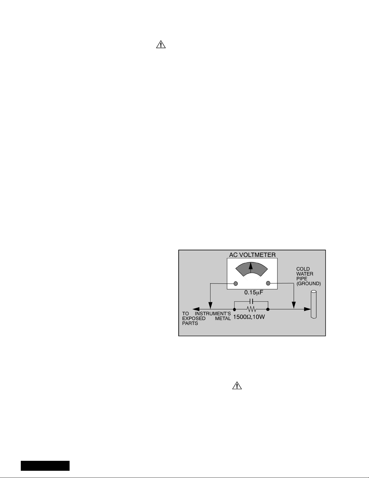
Leakage Current Hot Check (See Fig. 1)
Plug the AC cord directly into the AC outlet. Do not use
an isolation transformer during the check.
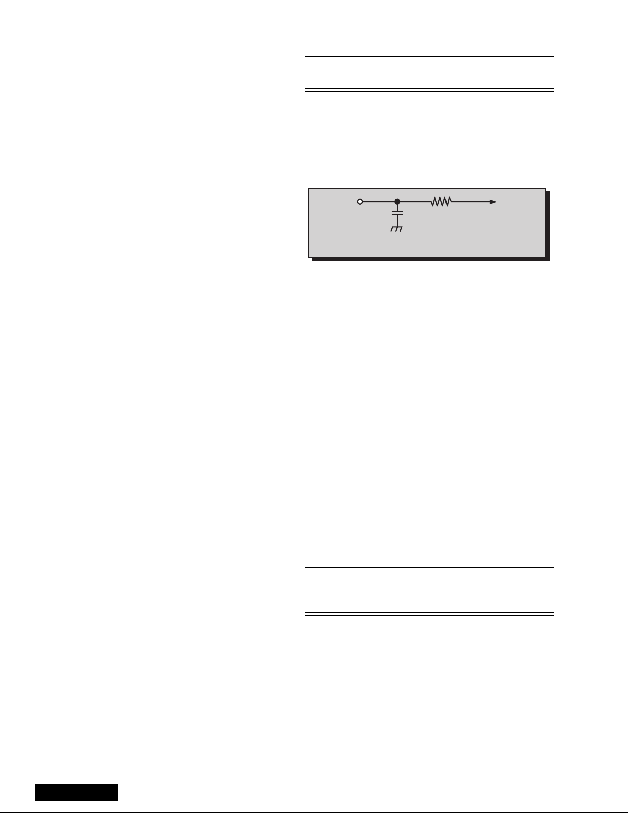
Connect a 1.5kW 10-watt resistor in parallel with a
0.15mF capacitor between and exposed metallic part
and ground. Use earth ground, for example a water
pipe.
Using a DVM with a 1000 ohms/volt sensitivity or
higher, measure the AC potential across the resistor.
Repeat the procedure and measure the voltage
present with all other expose metallic parts.
Verify any potential does not exceed 0.7 5 volt RMS. A
leakage current tester (such a Simpson Model 229,
Sencore Model PR57 or equivalent) may be used in
the above procedure, in which case any current
measure must not exceed 0.5 milliamp. If any
measurement is out of the specified limits, there is a
possibility of a shock hazard and the PTV must be
repaired and rechecked before it is returned to the
customer.
Figure 1. Hot Check Circuit
Insulation Test
Connect an insulation tester between an exposed
metallic part and AC line.
Apply 1080VAC/60Hz for 1 second. Confirm that the
current measurement is 0.5mA ~ 2.0mA. Repeat test
with other metallic exposed parts.
X-ray Radiation
WARNING: The potential source of X-ray radiation in the
PTV is in the hig h vo ltage section and t he pict ure t ube .
Note: It is important to use calibrated equipment.
Set brightness, picture, sharpness and color
controls to Minimum.
Measure the High Voltage. The high should be
31.5kV ± 1.0kV. If the upper limit is out of tolerance,
immediate servic e and correction is requ ired to insure
safe operation and to prevent the possibility of
premature component failu re.
- 2 -
Important Safety Tests
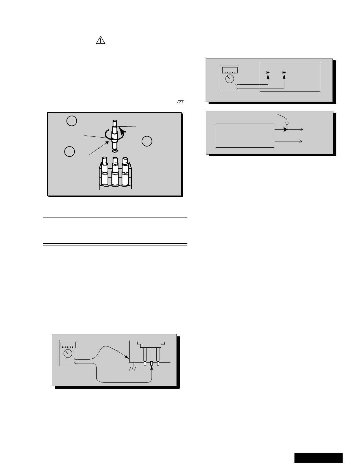
Measuring H.V.
The anode caps are cemented to the CRTs. To gain
access for high v oltage measurement, remove the red
CRT’s anode lead from the flyback transforme r (FBT)
distributor. Grasp the anode lead protective cap at its
bottom and squeeze it against the locking cap body
inside. Rotate 1/4 turn coun ter clockwise and pull the
anode lead sleeve out of the FBT distributor. Connect a
high voltage lead (+) from y our H.V. meter to the FBT
distributor, and the common (-) to cold ground ( ).
See Fig. 2.
1
Grasp protective
Anode lead
rubber cap
3
2
Squeeze & rotate
Discharge to
CRT Chassis
cap counterclockwise
to remove
FBT Distributor
Figure 2. Removal of FBT leads
Note: Reinsert the anode lead into the FBT
distributor until it is tightly and fully seated.
T urn the locking cap clockwise to lock in place.
(EHT) Protector Operation Check
With the cabinet ba ck removed, apply a n ominal 120V
AC to the PTV.
Over Voltage Test
Preparation:
1. Turn PTV “OFF”
2. Connect an NTSC signal generator to the antenna
terminal.
3. Connect DVM (+) TPA18 and (-) TPA19 on
A-Board. See Fig. 4.
4. Connect a H.V. meter (static type, class 0.1 ) with
high voltage leads to high voltage distributor
on FBT. See Fig. 4.
TPA19 TPA18
-
+
A-Board
DVM
Variable
Power
Supply
MA150
(8~15DC)
(+)
(-)
P-Board
TPP21
TPP20
Figure 4. DVM & Power supply connection.
5. Connect the 8 ~ 15V DC variable power supply to
(+) TPP21 and (-) TPP20, on P-Board. See Fig.4.
Procedures:
1. Apply a monoscope pattern.
2. Turn PTV “ON”.
3. Adjust the Pict ure or Brightness controls until th e
DVM reads 16.5 volts ± 0.5 volts.
4. Increase the variable power su pply unti l PTV turns
“OFF”. The set should turn off at 16.5 volts ± 0.5
volts (DVM) and high voltage less than 36.4kV.
5. If the DVM reading is other than 16.5 v olts (±0.5
volts), readjust picture or brightness control and
repeat steps 3.
6. Turn off the variable supply and confirm that the
PTV will turn on with the Remote Control.
-
+
H.V. METER
Cold Ground
FBT Distributor
CRT
CHASSIS
Figure 3. Measuring H.V.
- 3 -
Service Manual
Important Safety Notice . . . . . . . . . . . . . . . . . . . 2
Safety Precautions . . . . . . . . . . . . . . . . . 2
General Guidelines . . . . . . . . . . . . . . . . . 2
X-ray Precautions . . . . . . . . . . . . . . . . . . 2
Leakage Current Cold Check . . . . . . . . . 2
Leakage Current Hot Check . . . . . . . . . . 2
Insulation Test . . . . . . . . . . . . . . . . . . . . . 2
X-ray Radiation . . . . . . . . . . . . . . . . . . . . 2
Important Safety Tests. . . . . . . . . . . . . . . . . . . 3
Measuring H.V. . . . . . . . . . . . . . . . . . . . . 3
(EHT) Protector Operation Check . . . . . . 3
Service Notes . . . . . . . . . . . . . . . . . . . . . . . . . . . 5
Leadless Chip Component
(surface mount). . . . . . . . . . . . . . . . . 5
Component Removal. . . . . . . . . . . . . . . . 5
Chip Component Installation . . . . . . . . . . 5
How to Replace Flat-IC . . . . . . . . . . . . . . 5
Feature Table . . . . . . . . . . . . . . . . . . . . . . . . . . 6
PCB Designation . . . . . . . . . . . . . . . . . . . . . . . 7
PTV - Location of Controls . . . . . . . . . . . . . . . 8
Quick Reference Control Operation . . . . 8
Remote - Location of Controls . . . . . . . . . . . . . 9
Parts List . . . . . . . . . . . . . . . . . . . . . . . . . . . . . . 16
Description of Abbreviations Guide . . . . . . . . 27
Schematic Notes. . . . . . . . . . . . . . . . . . . . . . . . 27
A-Board layout & voltages . . . . . . . . . . . . . . . . . 31
A-Board schematic & waveforms . . . . . . . . . . . . 32
P-Board schematic & voltages . . . . . . . . . . . . . . 34
X-Board schematic & voltages . . . . . . . . . . . . . . 36
P-Board layout & waveforms . . . . . . . . . . . . . . . 38
X-Board layouts . . . . . . . . . . . . . . . . . . . . . . . . . 39
K, G & R-Board schematics & layouts . . . . . . . . 40
LB-Board schematic, layout & voltages . . . . . . . 41
LG-Board schematic, layout & voltages . . . . . . . 42
LR-Board schematic, layout & voltages . . . . . . . 43
Y-Board schematic, layout & voltages . . . . . . . . 44
Service Mode (Electronic Controls) . . . . . . . . 10
Quick Entry to Service Mode. . . . . . . . . 10
To toggle between Aging
and Service modes . . . . . . . . . . . . . 10
Exiting the Service Mode. . . . . . . . . . . . 10
To Check Purity . . . . . . . . . . . . . . . . . . . 10
B-Items, Service Sub Adjustments . . . . 11
C-Items, VCJ Cutoff Adjustments . . . . . 11
D-Items, Pincushion Adjustments . . . . . 11
P-Items, PIP Adjustments . . . . . . . . . . . 12
S-Option Items. . . . . . . . . . . . . . . . . . . . 12
X-Option Items. . . . . . . . . . . . . . . . . . . . 12
V-Option Adjustments . . . . . . . . . . . . . . 12
HV Feedback Voltage (D08) . . . . . . . . . 13
Sub-Bright Adjustment (B00). . . . . . . . . 13
Contrast Adjustment . . . . . . . . . . . . . . . 13
Red, Green & Blue Screen Cutoff . . . . . 14
White Balance Adjustment . . . . . . . . . . 14
Tint and Color Check. . . . . . . . . . . . . . . 14
MTS Circuit Adjustments . . . . . . . . . . . . 14
Input Level Adjustment (S06) . . . . . . . . 14
Stereo Separation Adjustment
(S07 & S08). . . . . . . . . . . . . . . . . . . 14
Clock Adjustment (S12). . . . . . . . . . . . . 15
PIP Adjustments . . . . . . . . . . . . . . . . . . 15
Service Manual
- 4 -
Service Notes
Note: Some components may be affixed wi th glue. B e careful not to bre ak or damag e foil un der the com ponent
or at the pins of th e ICs when removing . Usually applying he at to the component for a short time while
twisting with tweezers will break the component loose.
Leadless Chip Component
(surface mount)
Chip components must be replaced with identical chips
due to critical foil tr ack spacing. There are n o holes in
the board to mount standard transistors or diodes.
Some chips, capacitor or resistor board solder pads
may have holes t hrough the board, however the hol e
diameter limits standard resistor replacement to 1/8
watt. Standard capacitor may also be limited for the
same reason. It is recommended that identical
components be used.
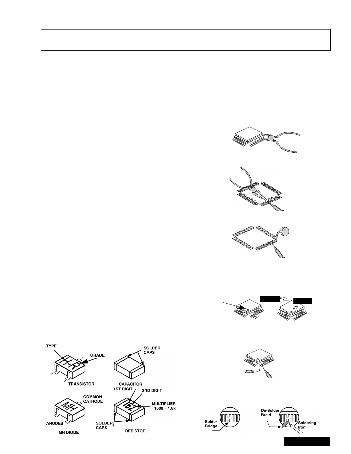
Chip resistors have a three-digit numerical resistance
code - 1st and 2nd significant digits and a multiplier.
Example: 162 = 1600 or 1.6kW resistor, 0 = 0W
(jumper).
Chip capacitors generally do not have the value
indicated on the capacitor. The color of th e componen t
indicates the general range of the capaci tance.
Chip transistors are identified by a two-lett er co de. T h e
first letter indicates the type and the second lette r, the
grade of transistor.
Chip diodes have a two-letter identification code as per
the code chart an d are a dual diode pack with either
common anode or common cathode. Check the parts
list for correct diode number.
Component Removal
7. Use solder wick to remove s older from compo nent
end caps or terminal.
8. Without pulling up, carefully twist the component
with tweezers to break the adhesive.
9. Do not reuse removed leadless or chip
components since they are subject to stress
fracture during removal.
Chip Component Installation
1. Put a small amount of solder on the board
soldering pads.
2. Hold the chip component against the soldering
pads with tweezers or with a miniature alligator clip
and apply heat to the pad area with a 30 watt iron
until solder flows. Do not appl y heat for more than
3 s econds.
Chip Components
How to Replace Flat-IC
- Required Tools -
• Soldering iron • De-solder braids
• Needle nose pliers • Magnifier
• Wire cutters (sharp & small)
1. Cut the pins of a defective IC with wire cutters.
Remove IC from boar d. If IC i s glued to the boa rd,
heat the IC and release the IC. See Note above.
Flat IC
2. Using soldering iron and needle nose pliers
remove the IC pins from the board.
Soldering
Iron
3. Using de-soldering braid and soldering iron remove
solder from affected are on board (pads).
De-soldering
Braid
Soldering
Iron
4. Position the new Flat-I C in place (app ly the pins of
the Flat-IC to the soldering pads where the pins
need to be soldered). Determine the positions of
the soldering pads and pins by correctly aligning
the polarity symbol. Solder pin #1 first, align the IC.
Polarity
symbol
Solder the pin op posite to pin #1. This will ass ist
positioning the IC.
5. Solder all pins to the soldering pads using a fine
tipped soldering iron.
2nd solder
1st solder
Solder
6. Check with a magnifier for solder bridge between
the pins or for dry join t between pi ns and sold erin g
pads. To remove a solder bridge, u se a de-solder
braid as shown in the figure below.
- 5 -
Soldering
Iron
Service Manual
IMPORTANT: To protect against possible damage to
the solid state devices due to arcing or static discharge,
make certain that all ground wires and CRT DA G wire
are securely connected.
CAUTION: The power supply circuit is above earth
ground and the chassis cannot be polarized. Use an
isolation transformer when s ervicing the PTV to avoid
damage to the test equipment or to the chassis.
Connect the test equipment to the proper ground (( )
or ( )) when servicing, or incorrect voltages will be
measured.
WARNING: This PTV has been designed to meet or
exceed applicable safety and X-ray radiation protection
Feature Table
as specified by gove rnment a genci es and ind ependen t
testing laboratories.
To maintain original product safety design standards
relative to X-ray radiation and shock and fire hazard,
parts indicated with the s ymbol on the schematic
must be replaced with identi cal parts. Order parts from
the manufacturer’s parts center using the parts
numbers listed in this service manual, or provide the
chassis number and the part reference number.
For optimum performance and readability, all other
parts should be replaced with components of identical
specification.
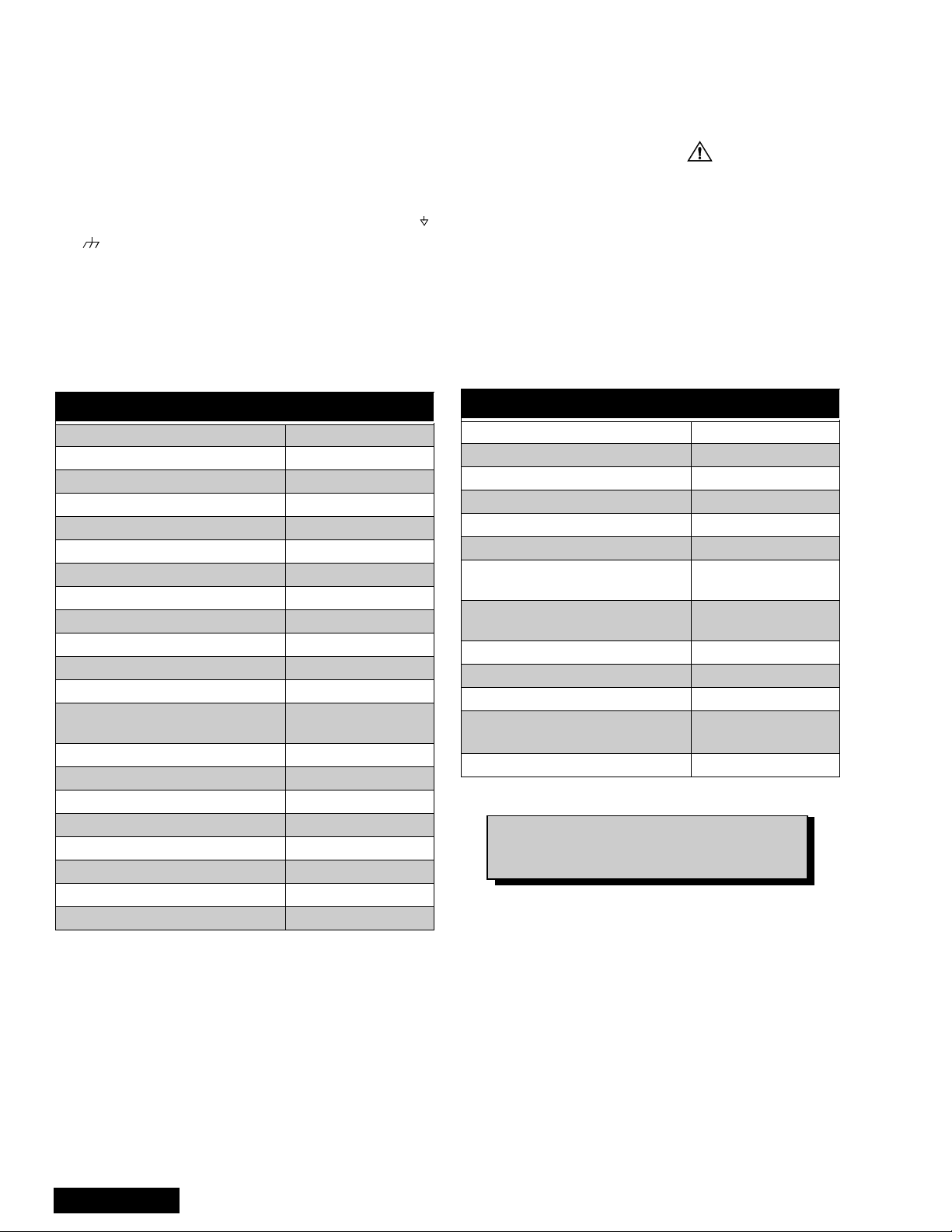
FEATURES
Chassis AP821
Tunning system 144K
# of channe ls 181
Menu language Eng/Span/Fr
Closed Caption X
V-Chip X
Picture in Picture (PIP) 2T
2 RF X
Remote model # EUR511500
CRT assembly - Red TXFCRT96SER
CRT assembly - Green TXFCRT95SER
CRT assembly - Blue TXFCRT94SER
Panablack picture tube
Comb filter 3 Line Digital
H. edge correction X
V/A Norm - Both X
Color temperature X
MTS/SAP/DBX X
AI sound X
Bass/Bl/Tre control X
Surround X
With Protective
Screen
FEATURES
BBE X
Built-in audio power 10W x 2 (10%)
# of speakers 2
A/V in (rear/front) 3(2/1)
S-VHS Input (rear/front) 1/0
Component Input 1
Audio Out
(FAO & VAO)
Dimensions mm
(WxDxH) in
Weight (kg/lbs) 86 / 189.6
Power source (V/Hz) 120 / 60
Anode voltage 31.5kV ± 1.0kV
Video input jack
Audio input jack 500mV RMS 47kW
1137 x 651 x 1361 .5
44.8 x 25.6 x 53.6
1V
X
75W, phono
p-p
jack
Table 1: PTV Feature Table
Specifications are subject to change
without notice or obligation.
Dimensions and weights are approximate.
Service Manual
- 6 -
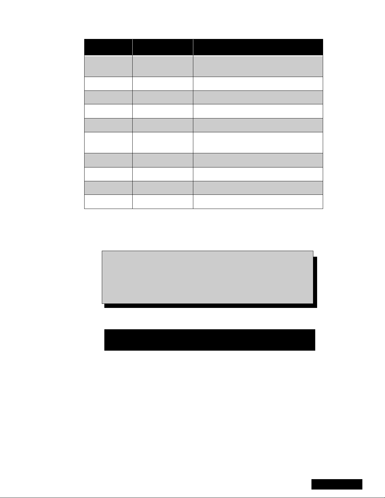
PCBs Designation
BOARD PART NUMBER BOARD DESCRIPTION
X-Board TNPA2055S
P-Board TNPA2056S Power Supply
LR-Board TNPA2057S RED Driver
LG-Board TNPA2058S GREEN Driver
LB-Board TNPA2059S BLUE Driver
A-Board TNPH0423S
G-Board TNP2AA081S Front AV Inputs
K-Board TNP2AA076S Button Panel
R-Board TNPA0615S IR Sensor
Y-Board TNPA1059BCS PIP Processing
Table 2: PCB Designation
Video Signal Processing, MPU, VCJ, Digital
Convergence, Comb Filter
Main Board, Sound Signal Processing,
Vertical Out, Vertical Drive, Audio Amplifier
Note: Components on the X-Board (
IC101, IC002, IC6501, IC005 and IC7102 are non-serviceable.
Referring to foldouts on page 37 for voltages may help identifying
damaged components. If any of the listed ICs is defective
replace it with a ne w IC; see parts list for or dering replacement
components. If other components failed, replace the board.
TNPA2055
S) except to IC001,
Important Notice
When replacing the X-Boa rd - transfer IC7102 (EEP ROM) f rom the
defective board to the new board.
- 7 -
Service Manual
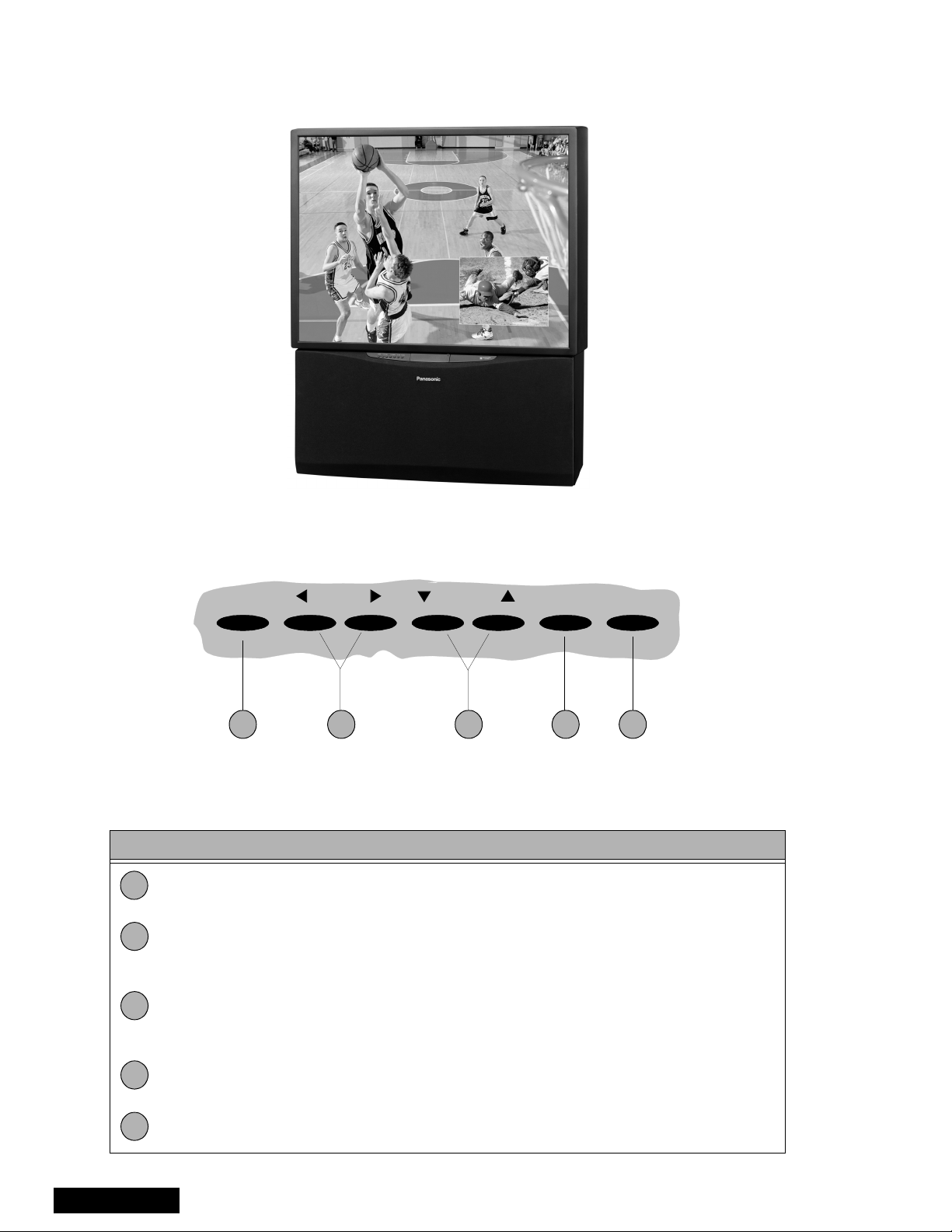
PTV - Location of Controls
POWER VOLUME CHANNEL ACTION TV/VIDEO
1 2 4 53
Figure 5. Location of Controls PTV
Quick Reference Control Operation
Quick Reference Control Operation
1
2
3
Power - Press to turn “ON” or “OFF”.
Vo lu m e - Press to adjust Sound Le vel, or to adjust A udio Menus, Video Menus , and
select operating features when menus are displayed.
Channel - Press to s elect programm ed channels. Pres s to highlight des ired features
when menus are displayed. Also use to select Cable Converter box channels after
programming Remote Control Infra-red codes (the TV/AUX/CABLE switch must be set
in CABLE position).
4
5
Service Manual
Action - Press to displ ay Main Menu and access On Screen f eature and Ad justment
Menus.
TV/Video - Press to select TV or one of the Video Inputs, for the Main Picture or the
PIP frame (when PIP frame is displayed).
- 8 -
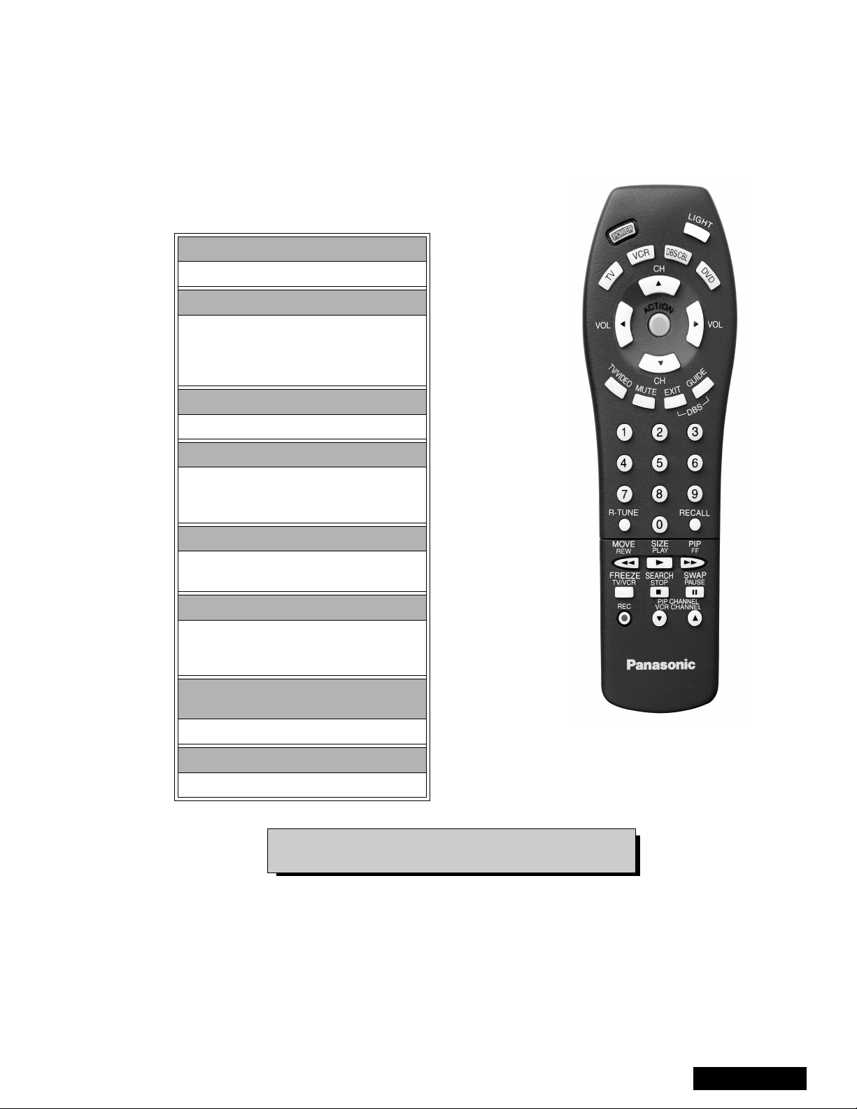
Remote - Location of Controls
POWER Button
Press to turn “ON” and “OFF”.
MUTE Button
Press to mute sound.
A second press resumes sound.
Press also to access and delete
Closed Caption display.
TV, VCR, DVD, CBS/CBL
Component function buttons
VOL (volume) Buttons
Press to adjust TV sound level.
Use with Channel buttons to
navigate in menus.
R-TUNE (Rapid Tune) Button.
Press to switch to the previous
channel.
ACTION Button
Press to display Main Menu and access or
exit On Screen features
and Adjustment Menus.
REW, PLAY, FF, TV/VCR, STOP, PAUSE,
REC & VCR CHANNEL Buttons
Component function buttons.
DBS EXIT& DBS GUIDE Buttons
DBS function buttons.
For additional information on this remote please refer to
the Remote Guide, listed on the parts list.
Figure 6. Location of Controls (EUR511500 Remote)
- 9 -
Service Manual
Service Mode (Electronic Controls)
To toggle between Aging and Service
modes:
While the “CHK” is di splayed on the left top corner
of the Screen, pressing “ACTION” and “VOL UP” on
the PTV simultaneously toggles between the
modes. Red “CHK” for Service and yellow “CHK” for
Aging.
This PTV has electronic techno logy using the I²C Bus
Concept. It performs as a control function and it
replaces many mechanical controls. Instead of
adjusting mechanical controls indivi dually, many of the
control functions are now performed by using “On
Screen Display Menu”. (The Service Adjustment
Mode.)
Note: It is suggested that th e techni cian rea ds all th e
way through and understand the following
procedure for Entering/Exiting the Service
Adjustment Mode and then proceed with the
instructions working with the PTV.
Quick Entry to Service Mode:
When minor adjustments need to be done to the
electronic controls, the me thod of Entering the S ervice
Mode without removal of th e cabi net bac k is as fo llows
using the Remote Control:
1. Select SET-UP icon and select CABLE mode.
2. Select TIMER icon and set SLEEP time for 30 Min.
3. Press “ACTION” twice to exit menus.
4. Tune to the Channel 124.
5. Adjust VOLUME to minimum (0).
6. Press VOL (decrease) on PTV. Red “CHK”
appears in upper corner.
8. “CHK” = Normal operation of CHANNEL
and VOLUME .
b
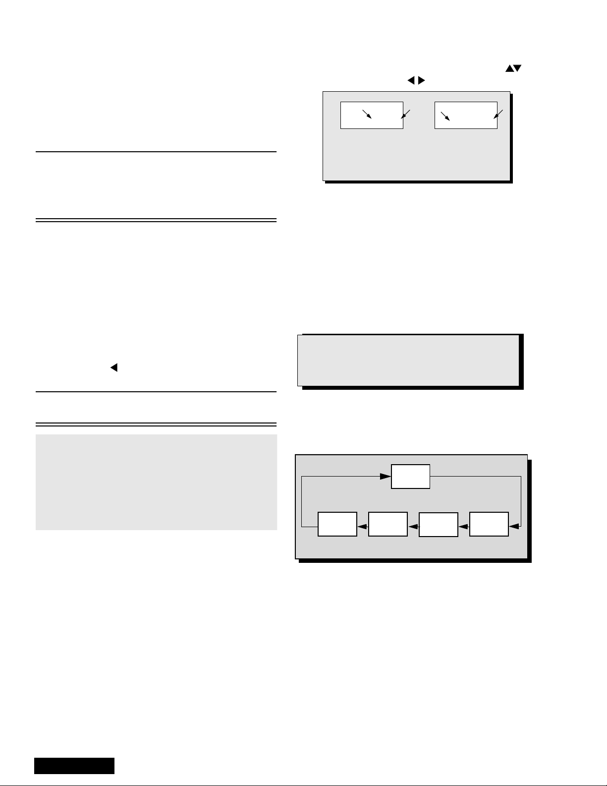
32 B 0 2 215 C 0
An address Menu appears in the right
hand corner of the screen
a
b
a
Figure 7. Service Mode Menu Adjustments.
Exiting the Service Mode:
Press “ACTION” and “POWER” on the PTV
simultaneously for at least 2 second s.
THE PTV EXITS SERVICE MODE.
The PTV momentarily shuts off; then comes back on
tuned to channel 3 with a preset level of audio.
Any programmed c hannel s, ch annels capt ion data an d
some others user defined settings will be erased.
NOTE
Always Exit the Service Mode
Following Adjustments.
Note: After PTV is set into SERVICE mode, set
TIMER back to NO.
7. Press “POWER” on the Remote Control to select
one of the Service Adjustment Modes.
1. B= Service VCJ SUB-DATA Adjustment s.
2. C= Service VCJ CUT-OFF Adjustments.
3. D= Service PINCUSHION Adjustments.
4. P= Servic e PIP Adjustments.
5. S =Service S OPTION Adjustments .
6. X =Service X OPTION Adjustments .
7. V= Service Y OPTION Adjustments.
To Check Purity:
Press “RECALL” on the Remote Control when in
Service Mode (red “CHK” is displayed) to enter the
Purity Field Check Mode.
NORMAL
SCREEN
Press “RECALL” again to select desired field.
BLUE
SCREEN
GRN.
SCREEN
RED
SCREEN
Figure 8. Purity Check Field Mode.
WHITE
SCREEN
Service Manual
- 10 -
Note: Registers marked as FIXED are factory preset.
The default value must not be changed.
Important Note:
Write down the original values (“b” in the
adjustment mode details, Fig. 7 ) for each address
adjustment before modifying values.
Follow the procedure bel ow to access various Servic e
adjustments. (Same procedures apply to each section.)
a. Press CH on the Remote Control to select
any of the seven Service Sub Adjustment
Addresses. (“a” in Fig. 7.)
b. Press on the Remote Control to adjust
the level of the selected Service Adj ustments.
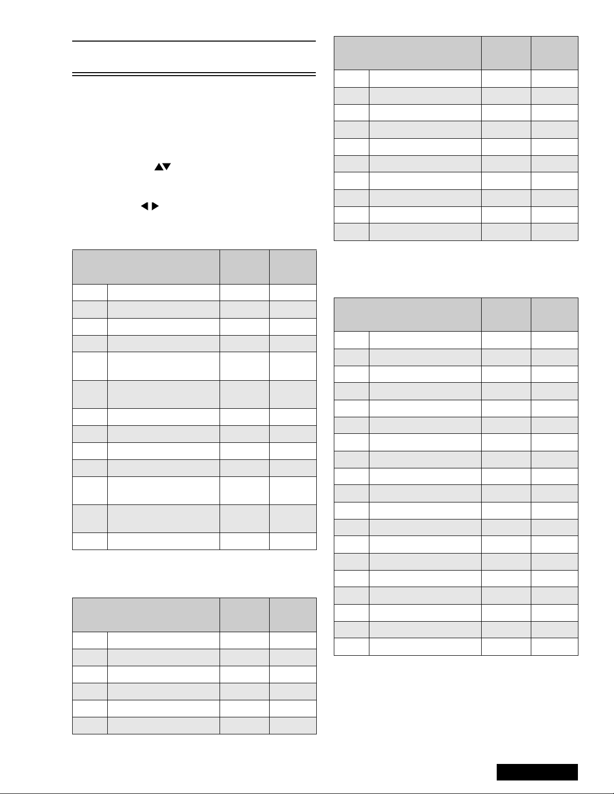
B Items: Service Sub Adjustments
Service Adjustment
B00 Sub B rightness 0 ~ 127 44
B01 Sub Contrast (RF) 0 ~ 15 5
B02 Sub C olor 0 ~ 63 18
B03 Sub Tint 0 ~ 63 34
B04
B05
B06 Sub Color (Video) FIXED 127
B07 Sub Tint (Video) FIXED 127
B08 Sub C olor (Component) FIXED 127
B09 Sub Tint (Component) FIXED 75
B0A
B0B
B0C Sub Contrast ---- ----
Sub Brightness
(Video/Component)
Sub Contrast
(Video/Component)
Sub Sharpness
(RF/Video)
Sub Sharpness
(Component)
Adj.
Range
FIXED 127
FIXED 16
FIXED 15
FIXED 20
Table 3: S e rvi ce Adj. B00 ~ B0C
Default
Level
Service Adjustment
C06 G CutOff (Video) FIXED 127
C07 B CutOff (Video) FIXED 127
C08 G Drive (Video) FIXED 127
C09 B Drive (Video) FIXED 127
C0A G CutOff (Component) FIXED 127
C0B B CutOff (Component) FIXED 127
C0C G Drive (Component) FIXED 127
C0D B Drive (Component) FIXED 127
C0E Drive Color Temp. FIXED 8
C0F Contrast Color Temp. FIXED 5
Adj.
Range
Default
Level
Table 4: Service Adj. C00 ~ C0F (Continued)
D Items: Pincushion Adjustments
Service Adjustment
D00 Vertical Amplitude 0 ~ 30 20
D01 Vertical Linearity 0 ~ 15 13
D02 Vertical S Correction 0 ~ 7 6
D03 Horizontal Amplitude 0 ~ 63 30
D04 Horizontal Centering 0 ~ 31 17
D05 EW Parabola 0 ~ 31 6
D06 Trapezoid 0 ~ 15 5
D07 EW Corner 2 0 ~ 15 8
D08 H EHT Correction 0 ~ 255 8
D09 Vertical Amplitude FIXED 3
D0A V BLK Start Phase FIXED 12
D0B V BLK Stop Phase FIXED 14
D0C V AGC FIXED 1
D0D Vertical Centering FIXED 63
Adj.
Range
Default
Level
C Items: VCJ Cutoff Adjustments
Service Adjustment
C00 R Cutoff 0 ~ 255 128
C01 G Cutoff (RF) 0 ~ 255 128
C02 B Cutoff 0 ~ 255 129
C03 Brightness FIXED 31
C04 G Drive (RF) 0 ~ 127 65
C05 B Drive (RF) 0 ~ 127 66
Adj.
Range
Table 4: Service Adj. C00 ~ C0F
Default
Level
D0E V Cent. DAC SW FIXED 0
D0F Conver. FIXED 0
D10 Free Run ON/OFF FIXED 0
D11 V Size Off Set FIXED 2
D12 V Lin Off Set FIXED 8
Table 5: Service Adj. D0 0 ~ D12
- 11 -
Service Manual
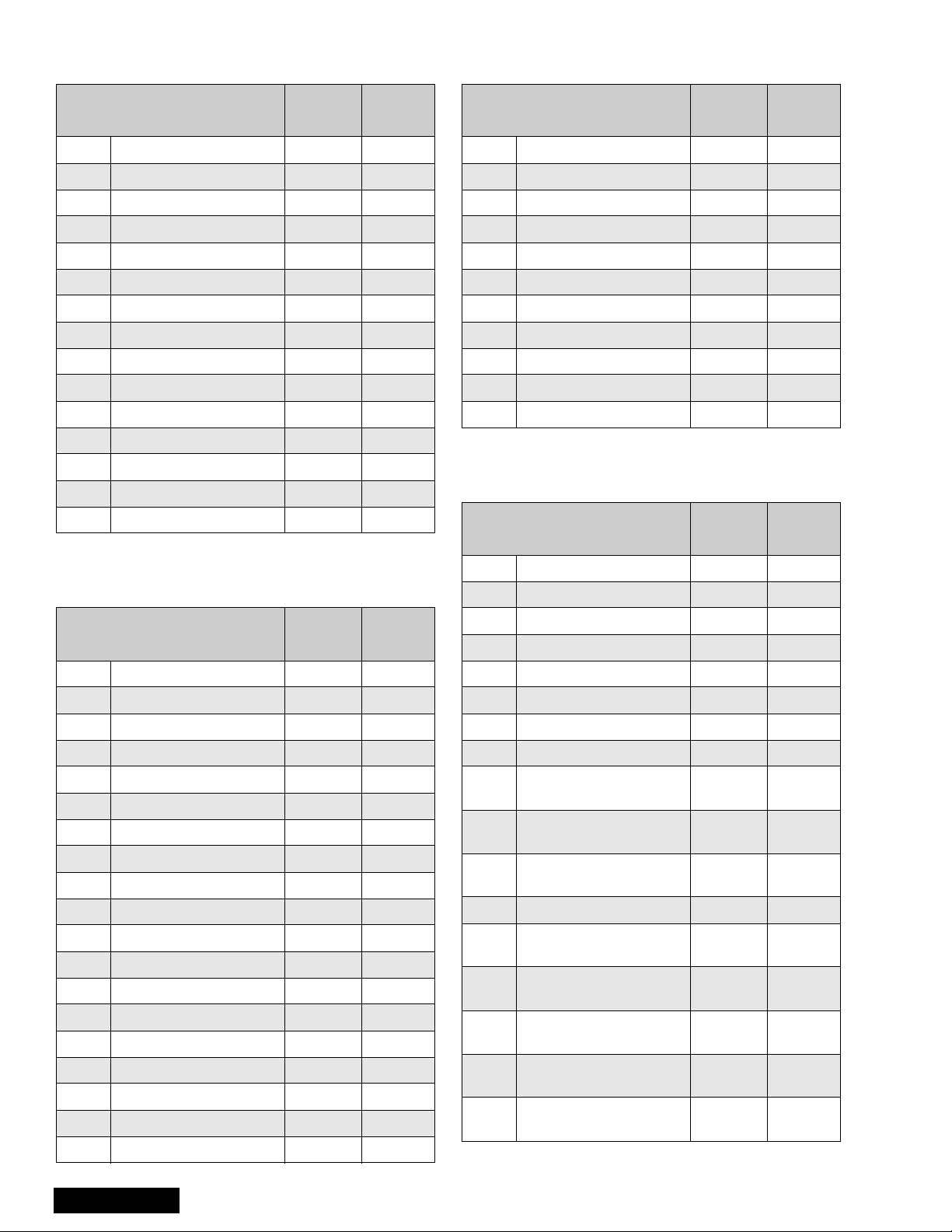
P Items: PIP Adjustments
X Option Items
Service Adjustment
P00 PIP Color FIXED 92
P01 PIP Tint FIXED 54
P02 PIP Brightness 0 ~ 31 22
P03 PIP Contrast 0 ~ 12 7 80
P04 PIP V Position 9 Up FIXED 27
P05 PIP V Position 9 Down FIXED 143
P06 PIP H Position 9 Left FIXED 12
P07 PIP H Position 9 Right FIXED 103
P08 PIP V Position 16 Up FIXED 27
P09 PIP V Posit 16 Down FIXED 161
P0A PIP H Position 16 Left FIXED 12
P0B PIP H Position 16 Right FIXED 118
P0C PIP Freerun ---- ---P0D PIP Y Delay FIXED 4
P0E PIP BG Start FIXED 17
Adj.
Range
Default
Level
Table 6: Service Adj. P00 ~ P0E
S Option Items
Service Adjustment
X00 Clip Level FIXED 8
X01 Correct Gain ---- ---X02 Limit Level FIXED 24
X03 Core Level FIXED 41
X04 C Delay (RF) FIXED 2
X05 C Delay (Video) FIXED 5
X06 VM Limit Level F IXED 90
X07 VM Core Level FIXED 8
X08 Sharpness FIXED 50
X09 VM Limit Level A FIXED 255
X0A VM Freq. SW FIXED 1
Adj.
Range
Default
Level
Table 8: Service Adj. X00 ~ X0A
V Option Adjustments
Service Adjustment
V00 Static Conv. Mode ---- ---V01 Point Conv . Mo de ---- ----
Adj.
Range
Default
Level
Service Adjustment
S00 B.S. Point FIXED 7
S01 RGB Gamma FIXED 1
S02 Col Gamma FIXED 0
S03 ABL Gain FIXED 2
S04 ABL Point FIXED 0
S05 RGB Brightness FIXED 10
S06 MTS Input Level 0 ~ 63 33
S07 MTS Low Separation 0 ~ 63 8
S08 MTS H i gh Separatio n 0 ~ 63 30
S09 Clock Adjustment 0 ~ 255 128
S0A Loudness Comp FIXED 7
S0B Caption Digital Filter SW FIXED 1
S0C Caption Scroll FIXED 1
S0D RGB MTX (RF/Video) FIXED 6
S0E RGB MTX (Component) FIXED 5
S0F BBE ON/OFF FIXED 1
S10 BBE Low Level FIXED 4
S11 BBE High Level FIXED 6
S12 Surround Effect FIXED 3
Adj.
Range
Default
Level
Table 7: Serviceman Adj. S00 ~ S12
Service Manual
V02 DAF Mode ---- ---V03 DAF ON/OFF FIXED 0
V04 ABL Input Level FIXED 10
V05 Blue Gamma FIXED 0
V06 VM ON/OFF FIXED 0
V07 ABL ON/OFF FIXED 0
V08
V09
V0A
V0B V1 Delay 0 ~ 255 1
V0C
V0D
V0E
V0F
V10
Test Pattern
Vertic al Phas e
Test Pattern
Vertical OSD
Test Pattern
Horizontal OSD
User St at ic Data
(Vertical, Red)
User St at ic Data
(Vertical, Green)
User St at ic Data
(Vertical, Blue)
User St at ic Data
(Horizon, Red)
User St at ic Data
(Horizon, Green)
0 ~ 255 20
0 ~ 255 29
0 ~ 255 65
FIXED 100
FIXED 100
FIXED 100
FIXED 100
FIXED 100
Table 9: Service Adj. V00 ~ V15
- 12 -
Service Adjustment
V1 1
V12
V13
V14
V15 Start Line (LOW) FIXED 11
User Static Data
(Horizon, Blue)
Test Pattern Horizon t al
Phase (LOW)
Test Pattern Fine
Horizontal Phase (LOW)
Test Pattern Coarse
Horizontal Phase (LOW)
Adj.
Range
FIXED 100
FIXED 90
FIXED 235
FIXED 0
Default
Level
Table 9: Service Adj. V00 ~ V15 (Continued)
HV_Feedback Voltage (D08)
Procedure:
1. Apply a NTSC all black pattern.
2. Connect meter (+) to TPA38 and (-) to TPA20.
3. Adjust DAC D08 until reading on meter is
5.0V ± 0.2V.
Sub-Bright Adjustment (B00)
Procedure:
1. Normalize picture.
2. Connect meter (+) to TPA18 and (-) to TNPA19.
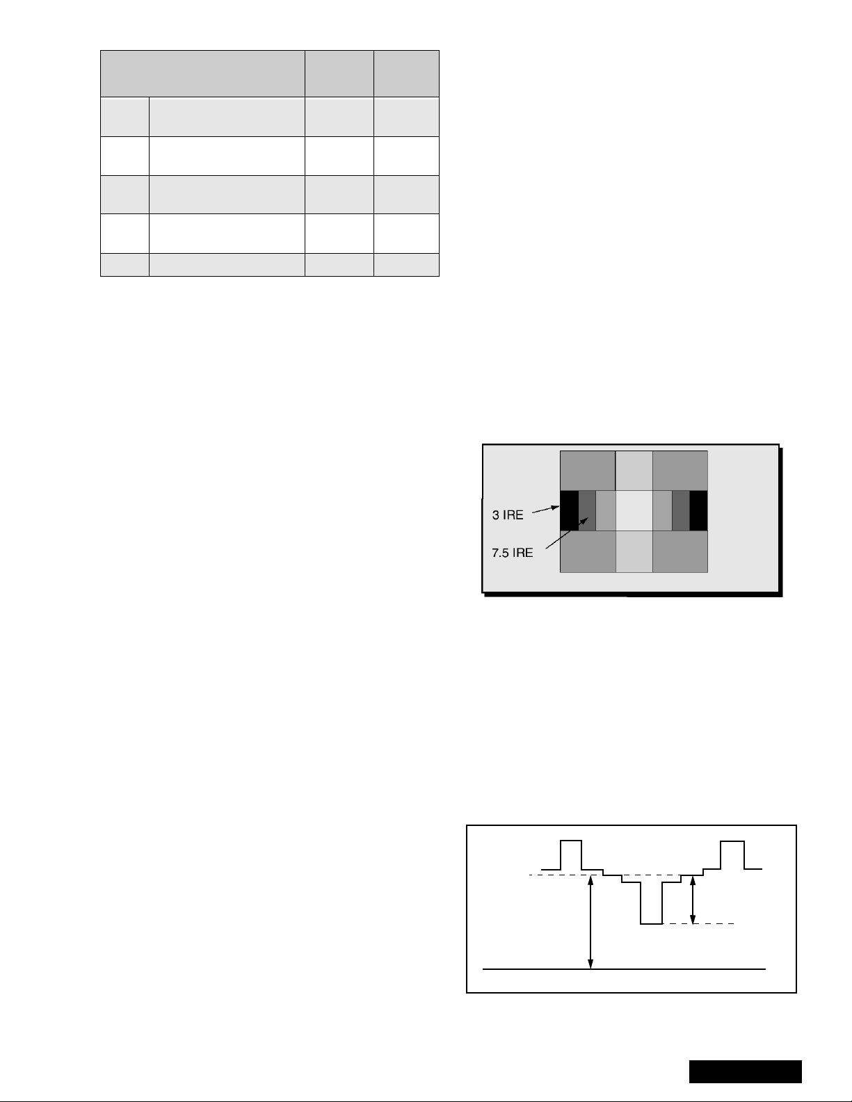
3. Apply a black level pattern.
4. Adjust DAC B00 (Sub-Brightn ess) until reading on
meter is 17.0V ± 1V (7.5 IRE part is same light
output as 3 IRE part. See Fig. 9.
5. Apply a monoscope pattern and adjust bright
control to max. and confirm same reading on
meter.
Contrast Adjustment
Preparation:
1. Set Auto Color and AI Picture to “OFF”.
2. Set the following in the user picture menu as
follows:
COLOR: min. (0)
PICTURE: max (63)
BRIGHT: center (31)
SHARPNESS: min. (0)
Set Cut Off Data:
• DAC C00 (R_CutOff) to 128.
• DAC C01 (G_RF CutOff) to 128.
• DAC C02 (B_CutOff) to 128.
• DAC C06 (G_Video CutOff) to 127.
• DAC C07 (B_Video CutOff) to 127.
• DAC C0A (G_Video Component) to 127.
• DAC C0B (B_Video Component) to 127.
Set Drive Data:
•DAC C04 (
•DAC C05 (B_Drive RF) to 64.
Procedure:
1. Use 100:1 probe for measurements.
2. Apply a black/white pattern. See Fig. 9.
G_Drive RF) to 64.
Figure 9. Black/white Pattern
3. Connect scope to TPLR1 and adjust Sub-Bright
(B00) data until voltage measured is 190V ± 2V.
See Fig. 10.
4. Connect scope to TPLG1 and adjust R-CutOff
(C00) data until voltage measured is 190V ± 2V.
See Fig. 10.
5. Connect scope to TPLB1 and adjust B-CutOff
(C02) data until voltage measured is 190V ± 2V.
See Fig. 10.
6. Connect scope to TPLR1 an d adjust Sub-Co ntrast
(B01) data to obtain 85V ± 2V between black
(7.5 IRE) and White level. See Fig. 10.
7.5 IRE
85V ± 2V (R)
190V±2V (R, G, B)
Use 100:1 Probe
GND
100 IRE
Figure 10. Contrast Adjustment.
- 13 -
Service Manual
Red, Green & Blue Screen Cutoff
1. Use either a no input signal condition or raster from
the NTSC generator.
2. Observing the green tube directly or via a reflective
surface, adjust the VR on the green tube for
minimum noise.
3. Adjust the noise level i n the red and blue tubes to
match the noise level in the green tube.
White Balance Adjustment
Prior to this adjustment, perform Contrast Adjustment.
This adjustment requires that the service technician
use skills in observing what a screen without color
should look like (White Picture).
1. Enter the service mode.
2. Apply a black a nd w hit e patter n t o one of the video
inputs.
High Light White Balance Adjustment
1. Adjust DAC C04 for green and C05 for blue
adjustments.
2. Make sure the screen is not blue or green. The
screen should be white in all areas.
3. Check the black and white pattern for a black and
white picture with even shades of gray and no color
tint in the picture.
Low Light White Balance Adjustment
1. Adjust DAC C01 for green and DAC C02 for blue.
2. Check the screen for even pure white in all areas.
3. Check the black and white pattern for a black and
white picture, even shades of gray and no color tint
in the low light areas.
4. Repeat the High Light and Low Light White
Balance again until the white bal ance tracks from
high light to low light.
Tint and Color Check
Again, the service technician ability to see color and
the balance of color is important for these adjustments.
Tint Check
1. In Picture Menu set Picture Norm to YES.
2. Apply color bars to the video input.
3. Magenta is composed of two colors, blue and red.
4. Check to see that magenta does not have too
much blue or too much red.
5. Check cyan. Cyan is c omposed of blu e and green .
It should not have too much blue or green.
6. Use a test signal from a V CR or la se r dis k that has
a pre-recorded close up of a sign al that has good
flesh tones.
7. The signal on the VCR or laser disk should look
normal.
Color Check
Using a clean RF or video s ignal, s et the col or level so
that it does not sat urate or appear harsh. Make sure
that color is n ot set so that it a ppears du ll and washed
out. Look for natural co lors; try to adjust the pic ture to
appear as a normal photograph.
MTS Circuit Adjustments
Note: It is important to a djust the MTS circuit in the
order shown below.
The MTS Circuit Adjustments require two steps:
1. Input Level Adjustment.
2. Stereo Separation Adjustment.
Input Level Adjustment (S06)
Preparation:
1. Connect an RMS meter (AC Range) with fil ter jig
as shown in Fig. 11.
RMS
METER
10k
TPE11
L_OUT
4700p
Figure 11. Filter Jig
2. Connect an RF signal generator to the RF
antenna input.
Procedure:
1. Apply the following signal from the RF signal
generator:
Video: 100 IRE flat field, 30% modulation.
Audio: 300Hz, 100% modulation, monaural
(70 ± 5dB/mV, 75Ω OPEN, P/S 10dB). Make sur e
to turn off 75ms pre-emphasis.
2. Adjust (S6)
measured is 106mV ± 6.0mV rms.
MTS-INPUT
data until the voltage
Stereo Separation Adjustment (S07 & S08)
Preparation:
1. Connect an RF signal generator to the RF
antenna input.
2. Connect an oscilloscope probe to TPE10 (R_out).
Procedure:
1. Set PTV to Stereo Mode (in the Audio Menu).
2. Apply the following signal from the RF signal
generator:
Video: 100 IRE flat field, 30% modulation.
Audio: 300Hz, 30% modulation, stereo (left only)
(70 ± 5dB/mV, 75Ω OPEN, P/S 10dB).
Note: Set the 30% modulation with the pilot light SW
and N.R. switches “OFF” then turn the m “ON”
while testing.
3. Adjust MTS Low-Level Separation (S07) data (in
the Service Adjus tment Menu) until the amplitude
of the measured waveform on the scope is
minimum.
4. Apply the following signal from the RF
signal generator:
Video: 100 IRE flat field, 30% modulation. Audio:
3KHz, 30% modulation, stereo (left only).
(70 ± 5dB/mV, 75Ω OPEN, P/S 10dB).
Service Manual
- 14 -
 Loading...