

Panasonic PN23129A, PN23249A, PN23169A Operation Manual
Thank you for purchasing our product.
This manual provides important information about safe and proper operations of this Switching
Hub.
Please read the "Important Safety Instructions" on pages 3 to 5.
Any problems or damage resulting from disassembly of this Switching Hub by customers
are not covered by the warranty.
Layer 2 Switching Hub
Operation Manual
For CLI Screens
Model Number: PN23129A
PN23249A

This operation manual is applicable to the following Switching Hubs:
Product name Model No.
Switch-M12PWR PN23129A
Switch-M24PWR PN23249A
3
Important Safety Instructions
This chapter contains important safety instructions for preventing bodily injury and/or property
damage. You are required to follow them.
Severity of bodily injury and/or property damage, which could result from incorrect use of
the Switching Hub, are explained below.
The following symbols are used to classify and describe the type of instructions to be observed.
This symbol is used to alert users
to what they must not do.
Do not use power other than AC 100 - 240V.
Deviation could lead to fire, electric shock, and/or equipment failure.
Do not handle the power cord with wet hand.
Deviation could lead to electric shock and/or equipment failure.
Do not handle this Switching Hub and connection cables during a thunderstorm.
Deviation could lead to electric shock.
Do not disassemble and/or modify this Switching Hub.
Deviation could lead to fire, electric shock, and/or equipment failure.
Do not damage the power cord. Do not bend too tightly, stretch, twist, bundle with other
cord, pinch, put under a heavy object, and/or heat it.
Damaged the cord could lead to fire, short, and/or electric shock.
Do not put foreign objects (such as metal and combustible) into the opening (such as
twisted pair port, console port, SFP extension slot), and/or do not drop them into the
inside of the Switching Hub.
Deviation could lead to fire, electric shock, and/or equipment failure.
Do not connect equipments other than 10BASE-T/100BASE-TX/1000BASE-T to
twisted pair port.
Deviation could lead to fire, electric shock, and/or equipment failure.
Do not place this Switching Hub in harsh environment (such as near water, high humid,
and/or high dust).
Deviation could lead to fire, electric shock, and/or equipment failure.
Do not place this Switching Hub under direct sun light and/or high temperature.
Deviation could lead to high internal temperature and fire.
WARNING
This symbol indicates safety instructions. Deviation from these
instructions could lead to bodily injury and/or property damage.
This symbol is used to alert users
to what they must do.
WARNING
This symbol indicates a potential hazard that could result in
serious injury or death.
CAUTION
4
Do not install this Switching Hub at the location with continuous vibration or strong
shock, or at the unstable location
Deviation could lead to injury and/or equipment failure.
Do not install any module other than the separately sold SFP module to SFP extension
slot.
Deviation could lead to fire, electric shock, and/or equipment failure.
Do not connect any cable other than the separately sold console cable.
Deviation could lead to fire, electric shock, and/or equipment failure.
Do not put this Switching Hub into fire.
Deviation could lead to explosion and/or fire.
Do not use the supplied power cord for anything other than this product.
Deviation could lead to fire, electric shock, and/or equipment failure.
Do not place this Switching Hub under direct sun light and or high temperature.
Deviation could lead to fire, electric shock, and/or equipment failure.
WARNING
WARNING
CAUTION
Use the bundled power cord (AC 100 – 240V specifications).
Deviation could lead to electric shock, malfunction, and/or equipment failure.
Unplug the power cord in case of equipment failure.
Deviation such as keeping connected for a long time, could lead to fire.
Connect this Switching Hub to ground.
Deviation could lead to electric shock, malfunction, and/or equipment failure.
Connect the power cord firmly to the power port.
Deviation could lead to electric fire, shock, and/or malfunction.
Unplug the power code in case of equipment failure.
Deviation, such as keeping connected for a long time, could lead to fire.
Unplug the power cord if the STATUS LED (Self-diagnosis) blinks in orange (system
fault).
Deviation, such as keeping connected for a long time, could lead to fire.
Handle the Switching Hub carefully so that fingers or hands may not be damaged by
twisted pair port, SFP extension slot, console port, or power cord hook block.

5
Basic Instructions for the Use of This Product
For inspection and/or repair, consult the retailer.
Use commercial power supply from a wall socket, which is close and easily accessible to this Switching
Hub.
Unplug the power cord when installing or moving this Switching Hub.
Unplug the power cord when cleaning this Switching Hub.
Use this Switching Hub within the specifications. Deviation could lead to malfunction.
Do not touch the metal terminal of the RJ45 connector, the modular plug of connected twisted pair
cable, or the metal terminal of the SFP extension slot. Do not place charged objects in the proximity
of them. Static electricity could lead to equipment failure.
Do not put the modular plug of the connected twisted pair cable on objects that can carry static charge,
such as carpet. Do not place it in the proximity. Static electricity could lead to equipment failure.
Do not put a strong shock, including dropping, to this Switching Hub. Deviation could lead to equipment
failure.
Before connecting a console cable to the console port, discharge static electricity, for example by touching
metal appliance (do not discharge by touching this Switching Hub).
Do not store and/or use this Switching Hub in the environment with the characteristics listed below.
(Store and/or use this Switching Hub in the environment in accordance with the specification.)
- High humidity. Possible spilled liquid (water).
- Dusty. Possible static charge (such as carpet).
- Under direct sunlight.
- Possible condensation. High/low temperature exceeding the specifications environment.
- Strong vibration and/or strong shock.
Please use this Switching Hub in place where ambient temperature is from 0 to 40℃.
For Switch-M12PWR:
When the total power supply is 140W or less, please use the Switching Hub in place where ambient
temperature is from 0 to 45℃.
When the total power supply is 110W or less, please use the Switching Hub in place where ambient
temperature is from 0 to 50℃.
For Switch-M24PWR:
When the total power supply is 145W or less, please use the Switching Hub in place where ambient
temperature is from 0 to 45℃.
When the total power supply is 130W or less, please use the Switching Hub in place where ambient
temperature is from 0 to 50℃.
Failure to meet the above conditions may result in fire, electric shock, breakdown, and/or malfunction.
Please take notice because such cases are out of guarantee.
Additionally, do not cover the bent hole of this Switching Hub.
Deviation could lead to high internal temperature, equipment failure and/or malfunction.
When stacking Switching Hubs, leave a minimum of 20 mm space between them is required.

6
1. Panasonic will not be liable for any damage resulting from the operation not in accordance with
this operation manual or the loss of communications, which may or may not be caused by failure
and/or malfunction of this device.
2. The contents described in this document may be changed without prior notice.
3. For any question, please contact the retailer where you purchased the product.
* Brands and product names in this document are trademarks or registered trademarks of their respective
holders.

7
Table of Contents
Important Safety Instructions ................................................................................3
Basic Instructions for the Use of This
Product ........................................................5
1. Command Hierarchy.......................................................................................8
2. Displaying Basic Information
.......................................................................... 12
3. Basic Switch Configuration ............................................................................ 13
3.1. System Administration Configuration ............................................................ 13
3.2. IP Address Configuration ......................................................................... 15
3.3. SNMP Configuration ............................................................................... 17
3.4. Port Configuration .................................................................................. 19
3.5. System Security Configuration ................................................................... 21
3.6. Displaying MAC Address Table ................................................................. 25
3.7. Time Configuration ................................................................................. 27
3.8. ARP Configuration.................................................................................. 28
4. Advanced Switch Configuration ....................................................................... 29
4.1. VLAN Configuration................................................................................. 29
4.2. Link Aggregation Configuration .................................................................. 31
4.3. Port Monitoring Configuration
.................................................................... 32
4.4. Spanning Tree Configuration..................................................................... 33
4.5. Access Control Configuration .................................................................... 37
4.6. QoS (Quality of Service) Configuration ..................................................... 40
4.7. Bandwidth Control Configuration................................................................. 42
4.8. IEEE802.1X Authentication Function Configuration
.......................................... 43
4.9. IGMP Snooping Configuration ................................................................... 45
4.10. PoE (Power Supply Function) Configuration
.............................................. 48
4.11. Storm Control Configuration ..................................................................... 49
4.12. Ring Protocol Configuration ..................................................................... 50
5. Displaying Statistic Information........................................................................ 51
6. Firmware Upgrade and Downloading/Uploading Configuration File
........................... 52
7. Reboot ..................................................................................................... 53
8. Ping Execution ........................................................................................... 54
9. Displaying System Log................................................................................. 55
10. Saving Configuration Information
.................................................................... 56
11. Displaying Configuration Information
................................................................ 57
Appendix A. Specifications
.............................................................................. 58
Appendix B. Proc
edures for Console Port Configuration using Windows HyperTerminal . 59
Appendix C. Easy I
P Address Setup Function .................................................... 60
Troubleshooting ............................................................................................... 61
After-sales Service.......................................................................................... 62
8
1. Command Hierarchy
There are four hierarchical levels in command hierarchy.
1. User mode
2. Privileged mode
3. Global configuration mode
4. Interface configuration mode
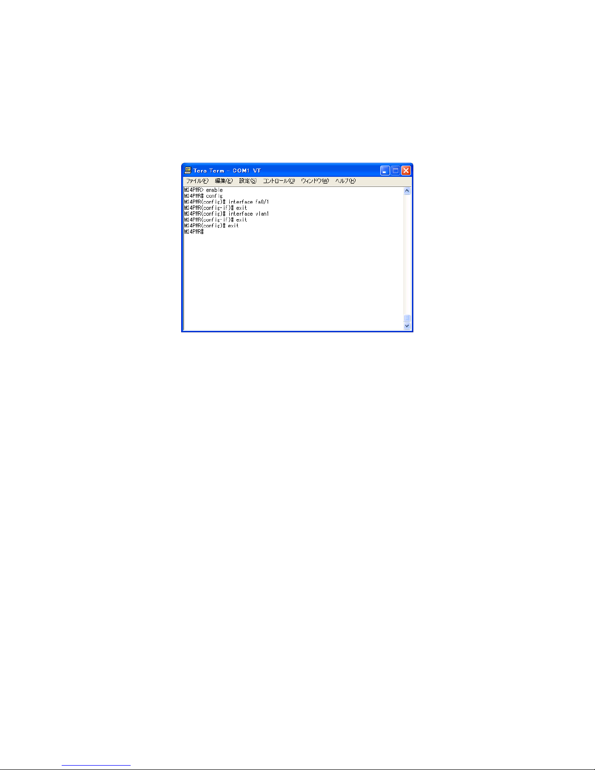
Fig. 1-1 Command hierarchy
[enable command]
• The enable command enables to move from User mode to Privileged mode.
M24PWR> ···················································· User mode
M24PWR> enable············································ User mode
Privileged mode
M24PWR# ···················································· Privileged mode
M24PWR# disable ··········································· Privileged mode
User mode
M24PWR> ···················································· User mode
[disable command]
• The disable command enables to return from Privileged mode to User mode.
M24PWR# ···················································· Privileged mode
M24PWR# disable ··········································· Privileged mode
User mode
M24PWR> ···················································· User mode

9
[config command]
• The config command enables to move from Privileged mode to Global configuration mode.
M24PWR# ···················································· Privileged mode
M24PWR# config ············································ Privileged mode
Global configuration mode
M24PWR(config)# ·········································· Global configuration mode
[interface command]
• The interface command enables to move from Global configuration mode to Interface configuration
mode.
M24PWR(config)# ·········································· Global configuration mode
M24PWR(config)# interface vlan1 ························· Global configuration mode
Interface
configuration mode (vlan1)
M24PWR(config-if)# exit ·································· Interface configuration mode
Global configuration mode
M24PWR(config)# interface fastethernet0/1 ·············· Global configuration mode
Interface
configuration mode (interface1)
M24PWR(config-if)#········································ Interface configuration mode
M24PWR(config)# ·········································· Global configuration mode
[exit command]
• The exit command enables to return to the previous mode.
M24PWR(config-if)# exit ·································· Interface configuration mode
Global configuration mode
M24PWR(config)# exit ····································· Global configuration mode
Privileged mode
M24PWR# exit··············································· Privileged mode
User mode
M24PWR> ···················································· User mode
[end command]
• The end command enables to move from configuration modes to Privileged mode.
M24PWR(config-if)# end ·································· Interface configuration mode
Privileged mode
M24PWR# config
M24PWR(config)# end ····································· Global configuration mode
Privileged mode
10
[? command]
• Entering a question mark (?) in each mode displays executable elements in the mode.
FFiigg.. 11--22 ?? ccoommmmaanndd
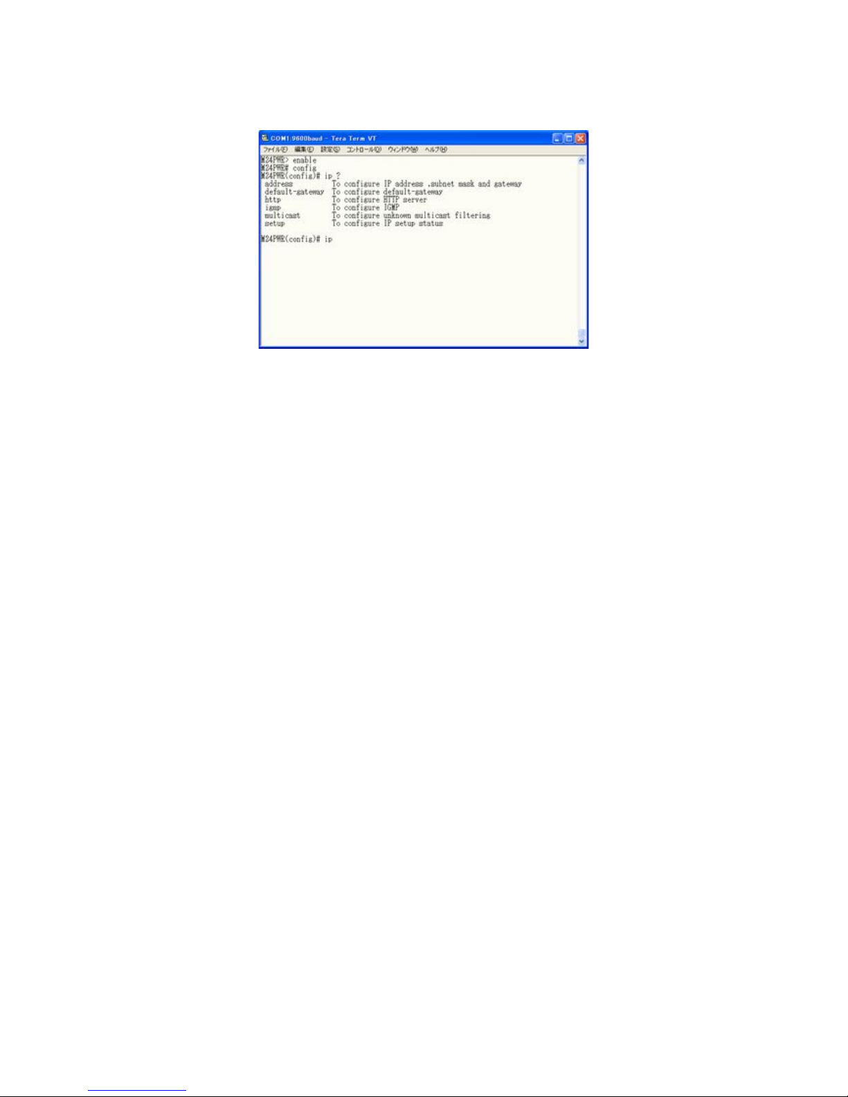
[Re-entry assist]
• Entering the up arrow key displays a command that was entered immediately before.
Fig. 1-3 Re-entry assist command
11
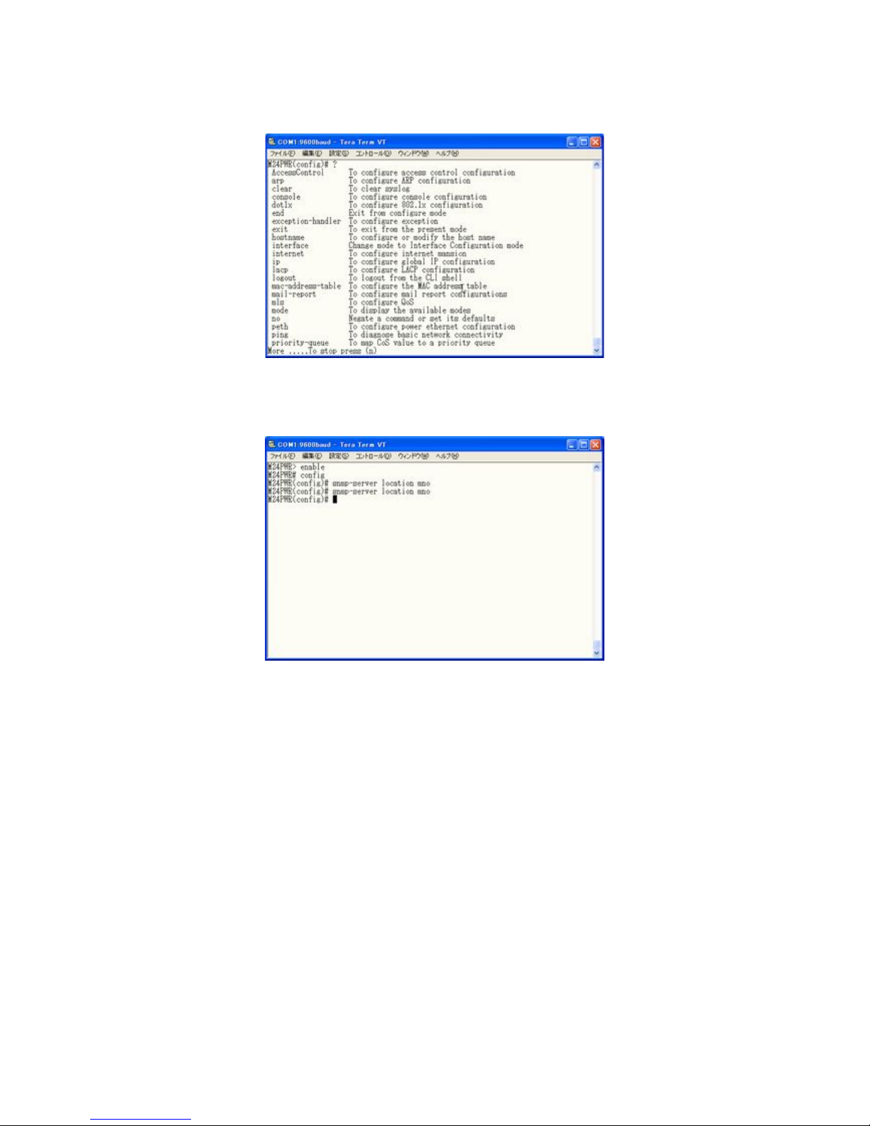
[Candidate assist command]
• Entering a command followed by a question mark (?) displays candidates of succeeding command.
FFiigg.. 11--44 CCaannddiiddaattee aassssiisstt ccoommmmaanndd
[[CCoommmmeenntt]
]
• Lines that begin with an exclamation mark (!) are ignored and regarded as comments.
This document describes how to use the commands that can be used in this switch. Meanings of
symbols in description are as follows:
< > : Essential element – Make sure to enter this element.
{ }: Choice – Select and input either one.
[ ]: Option – Enter as required.
12
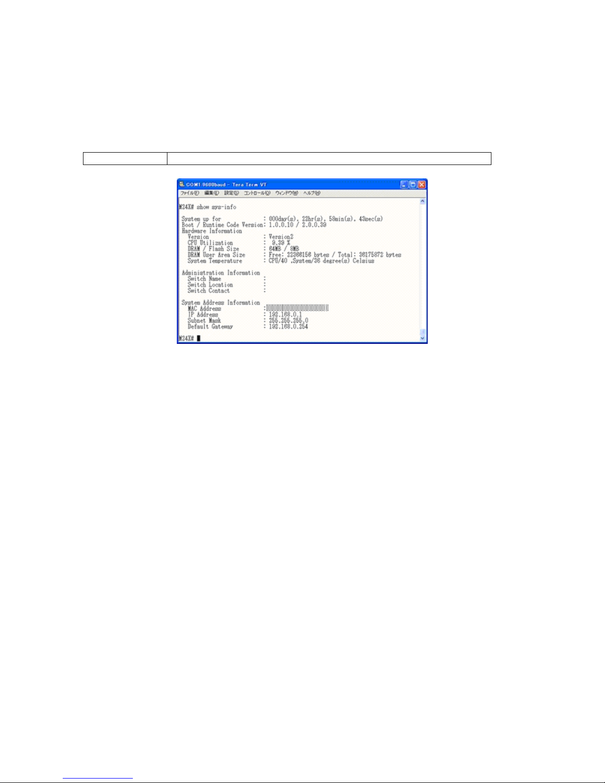
2. Displaying Basic Information
Enter "show sys-info" in "Privileged mode" to view the basic information of this switch as shown
in Fig. 2-1.
Basic information display command
Privileged mode show sys-info
Fig. 2-1 Display of the basic information
(show sys-info)

13
3. Basic Switch Configuration
3.1. System Administration Configuration
Configure the administrator's name, installation location and contact information in "Global configuration
mode." Confirm the configuration information by entering "show sys-info" in "Privileged mode."
Host name configuration command
Global configuration mode hostname <hostname>
Delete command
Global configuration mode no hostname
Installation location configuration command
Global configuration mode snmp-server location <server location>
Delete command
Global configuration mode no snmp-server location
Contact information configuration command
Global configuration mode snmp-server contact <server contact>
Delete command
Global configuration mode no snmp-server contact
Basic information display command
Privileged mode show sys-info
Note: When configuring a host name containing a space, enter it embracing with double quotation
marks (" ").
Example: hostname “Switch 1”
14
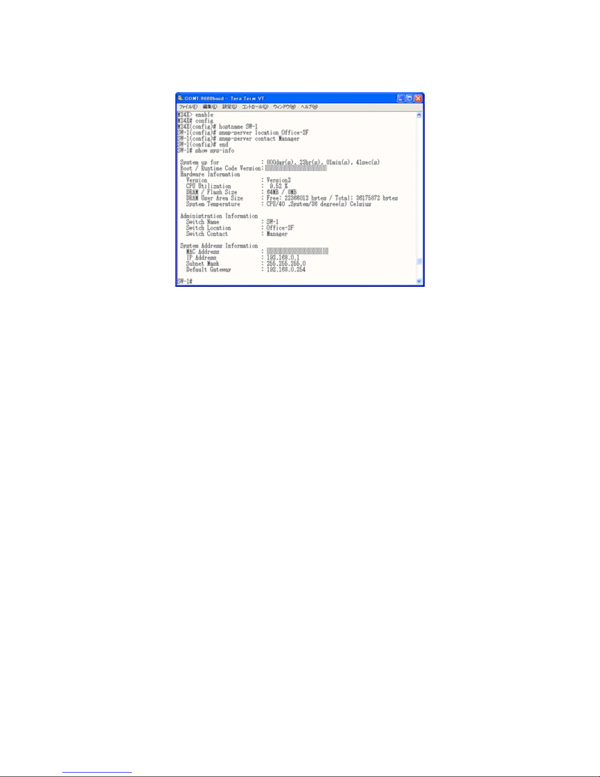
ex. Configuration example of host name as SW-1, installation location as Office-2F, and contact
information as Manager.
Fig. 3-1 Display of the administrator's name,
installation location and contact information configuration (show sys-info)
15
3.2. IP Address Configuration
Configure the IP address settings of this switch in "Interface configuration mode." Confirm the configuration
information by entering "show ip conf" in "Privileged mode."
IP address configuration command
Global configuration mode ip address <ip-address> <mask> [<default-gateway>]
Default gateway configuration command
Global configuration mode ip default-gateway <ip-address>
DHCP client configuration command
Global configuration mode ip address dhcp
DHCP address reacquisition command
Global configuration mode ip address renew
DHCP client configuration disable command
Global configuration mode no ip address dhcp
IP address display command
Privileged mode show ip conf
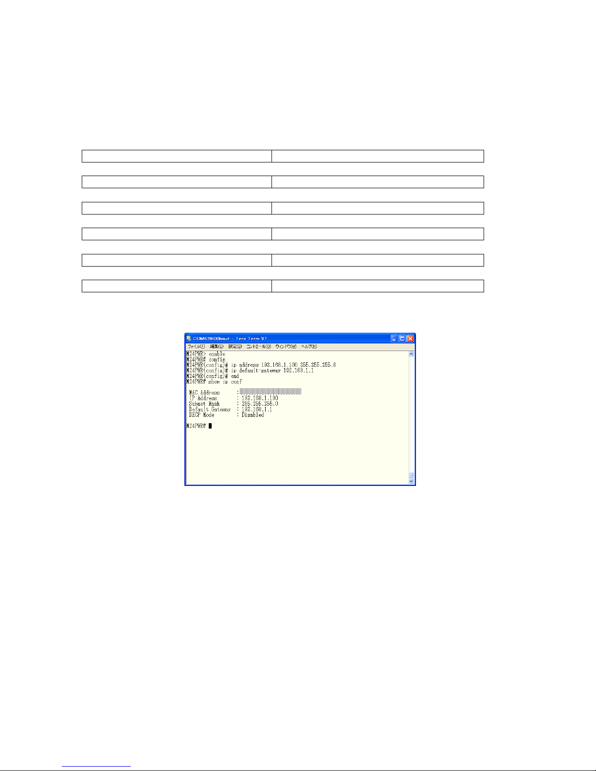
ex1. Configuration example of IP address as 192.168.1.100, subnet mask as 255.255.255.0, and
default gateway as 192.168.1.1
Fig. 3-2 Display of the IP address configuration
(show ip conf)
16
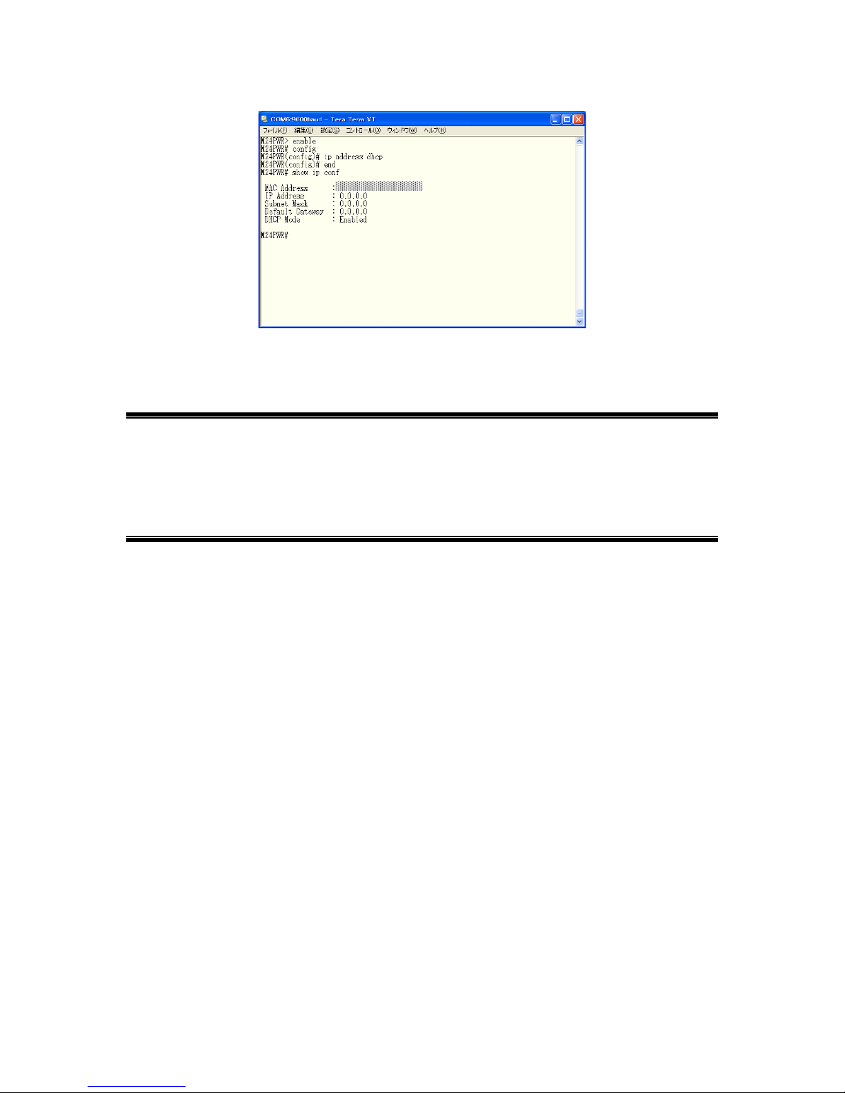
ex2. Configuration example of DHCP client
Fig. 3-3 Display of the DHCP client and IP address configuration
(show ip conf)
Note: The above items must be set in order to enable a remote connection by SNMP control function,
Telnet, SSH, or Japanese WEB control function. If you don't know items to be configured,
please consult with your network administrator. Any IP addresses on the local network must
be unique and no duplication is allowed. In addition, you need to set the subnet mask and
the default gateway, which are the same for other devices on the same subnet using this
switch.

17
3.3. SNMP Configuration
Configure the SNMP agent setting in "Global configuration mode." Confirm the configuration information
by entering "show snmp" in "Privileged mode."
SNMP enable command
Global configuration mode snmp-server agent
SNMP disable command
Global configuration mode no snmp-server agent
SNMP administration (Read only or Read/Write configuration) command
Global configuration mode snmp-server community <index> <community> {RO|RW} [<ip>]
SNMP administration configuration delete command
Global configuration mode no snmp-server community <index>
SNMP trap (type, IP address, community name configuration) command
Global configuration mode snmp-server host <index> type {v1|v2} <ip> trap <community>
SNMP trap configuration delete command
Global configuration mode no snmp-server host <index>
SNMP trap (authentication failure configuration) command
Global configuration mode snmp-server enable traps snmp authentication
SNMP trap (authentication failure configuration) delete command
Global configuration mode no snmp-server enable traps snmp authentication
SNMP trap (linkdown port configuration) command
Global configuration mode snmp-server enable traps linkupdown <1-2 or 1,2,3 or 1,2,3-5>
SNMP trap (linkdown port configuration) delete command
Global configuration mode no snmp-server enable traps linkupdown <1-2 or 1,2,3 or 1,2,3-5> }
SNMP trap (PoE operation configuration) command
Global configuration mode snmp-server enable traps poe
SNMP trap (PoE operation configuration) delete command
Global configuration mode no snmp-server enable traps poe
SNMP trap (FAN error detection configuration) command
Global configuration mode snmp-server enable traps fan-fail
SNMP trap (FAN error detection configuration) delete command
Global configuration mode no snmp-server enable traps fan-fail
SNMP trap (temperature detection) enable command
Global configuration mode snmp-server enable traps temperature-control
SNMP trap (temperature detection) disable command
Global configuration mode no snmp-server enable traps temperature-control
SNMP trap (temperature detection) temperature configuration command
Global configuration mode snmp-server enable traps temperature-threshold
<temperature>
SNMP display command
Privileged mode show snmp
18
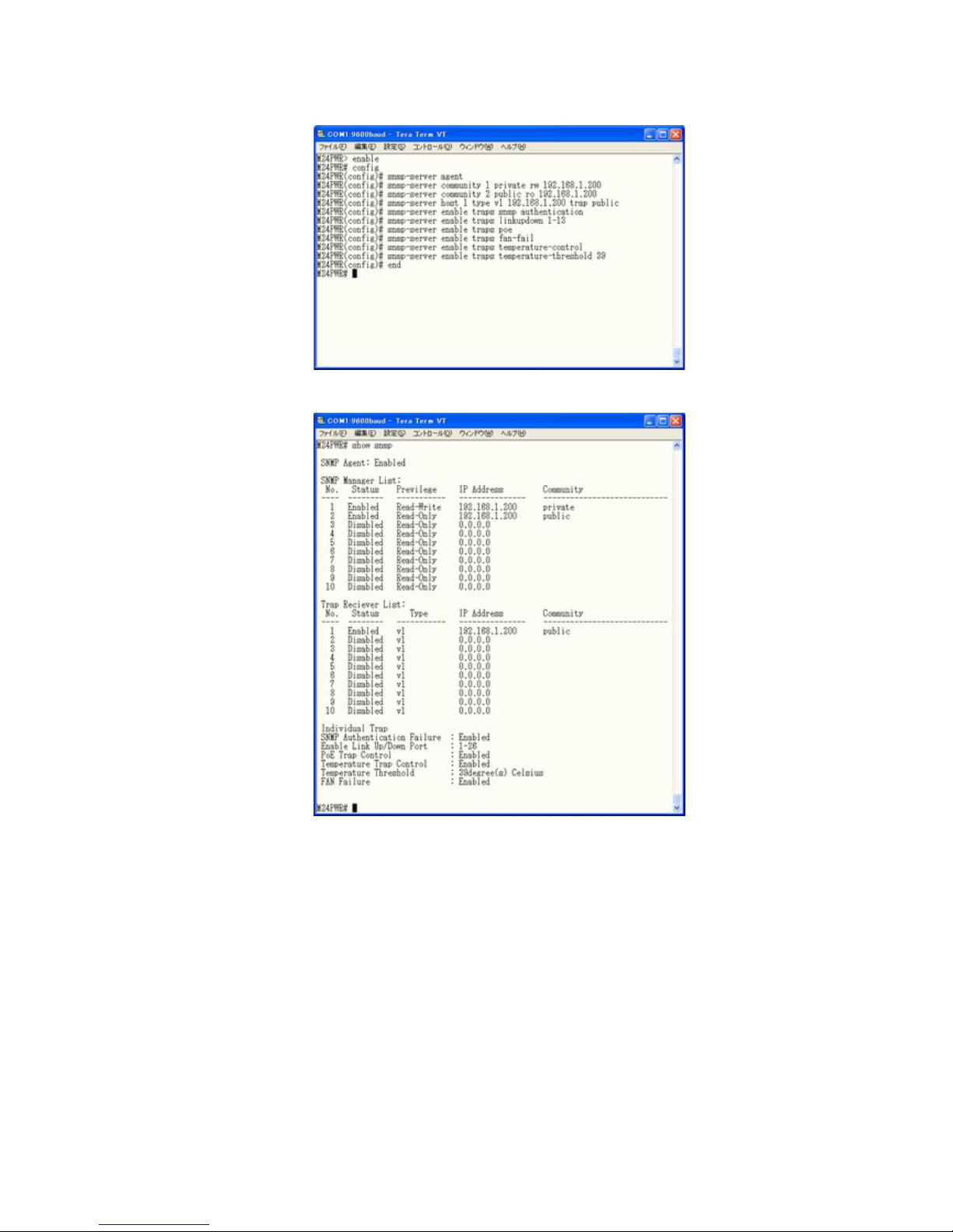
ex1. Configuration example of SNMP agent, SNMP manager, trap receiver, and various traps.
Fig. 3-4 Configuration of SNMP
Fig. 3-5 Display of the SNMP configuration
(show snmp)

19
3.4. Port Configuration
Display each port's status and configure the setting in "Interface configuration mode." Confirm the
configuration information by entering "show interface info"
in "Privileged mode."
Port status enable command
Interface configuration mode no shutdown
Port status disable command
Interface configuration mode shutdown
Port mode configuration command
Interface configuration mode speed-duplex
{ auto | {10|100}-half | {10|100}-full }
Flow control enable command
Interface configuration mode flow-control
Flow control disable command
Interface configuration mode no flow-control
Port name configuration command
Interface configuration mode name <string>
Auto MDI enable command
Interface configuration mode mdix auto
Auto MDI disable command
Interface configuration mode no mdix auto
Jumbo frame enable command
Interface configuration mode jumbo
Jumbo frame disable command
Interface configuration mode no jumbo
EAP packet transfer enable command
Interface configuration mode eap-forward
EAP packet transfer disable command
Interface configuration mode no eap-forward
Port information display command
Privileged mode show interface info
Port name display command
Privileged mode show interface name
Module information display command
Interface configuration mode getport
 Loading...