

Panasonic PM-F64 Installation Manual
INSTRUCTION MANUAL
Photo E lectric Sensor
Built-in U-shaped Micro-photosensor
PM-غ64
WARNING
٨
Never use this product as a sensing device for personnel
protection.
٨
In case of using sensing devices for personnel protection,
use products which meet laws and standards, such as
OSHA, ANSI or IEC etc., for personnel protection applicable in each region or country.
Since protection circuit against output short-circuit or reverse
٨
polarity connection is not incorporated, make sure to wire
correctly. Also, ensure to insulate the unused output wire.
Take care that wrong wiring will damage the sensor.
1
I/O CIRCUIT DIAGRAM
Color code of optional connector attached cable
(Brown) +V
oad
ut 2
p
L
oad
L
.
x
m
a
0m
5
A
.
50mA max
CN-14A-Cغ
<Connection connector>
Housing: PAP-04V-S
Manufactured by J.S.T. MFG
CO., LTD.
+
-
5to24VDC
r10%
(Brack) Output1
(White) Out
Sensor circuit
Internal circuit Users' circuit
2
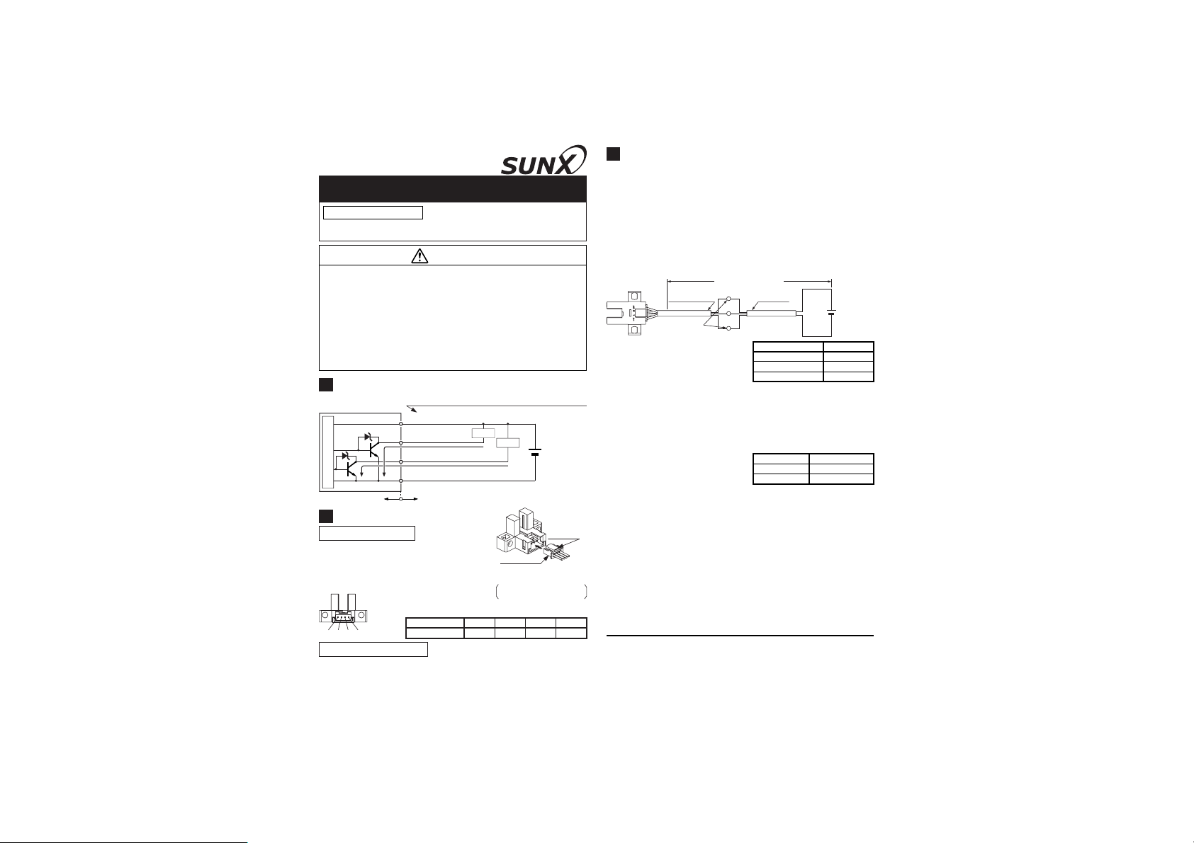
WIRING
(Blue) 0V
Connection method
٨ Insert the connector attached ca-
(CN-14A-Cغ) in the connection
ble
connector part of this product as
shown in the right figure.
<Connector pin position>
Projection
3
CAUTIONS
٨
Since the sensor is intended for use inside machines, no
special countermeasures have been taken against extraneous light. Please take care that extraneous light is not directly incident on the beam receiving section.
٨
If the sensor is used in a place having excessive dust, periodically clean the emitting and receiving sections with a dry, soft cloth.
Cable extension is possible up to an overall length of 100m
٨
with a 0.3mm
drop shall occur due to the cable extension, ensure that the
power supply voltage at the end of the cable attached to the
sensor or at the sensor terminals is within the rating.
But, when the overall cable
length, including the cable
attached to the sensor, is as
given below, there is no
need to confirm the voltage.
٨
If there is a large surge generating equipment, such as, motor, solenoid, electromagnetic valve, etc., in the vicinity of the
micro-photosensor, use a surge absorber on that equipment.
Further, do not run the sensor cables along power lines and
use a capacitor between +V and 0V, if required. Use the
sensor after confirming that the surge has been eliminated.
٨
In case the sensor is fixed
with screws, strictly observe
the following conditions.
Note: If the product is used at an ambient temperature of 50 or more, make
sure to mount it on a metallic body.
٨ Do not use the sensor in the transient time duration of 50ms
after switching on the power supply.
2
, or more, cable. However, since a voltage
Connector
attached cable
Supply voltage:
4.5V or more
Overall length: 100m
Extension
+V
cable
Output
0V
Wire conductor cross-section area
0.08 to 0.1mm2Up to 5m
Tigthening torque
Washer
2
0.2mm
2
0.3mm
Screw M3
+
5to24VDC
r10%
-
Overall cable length
Up to 10m
Up to 20m
0.5N㨯morless
Ǿ6mm (small diameter type)
ԘԙԚԛ
Connector pin No.
Terminal designation
ԙԚ0Vԛ
+VԘOutput 1 Output 2
Disconnection method
٨ Pressing the projection of the connection attached cable,
pull out the connector.
Note: Take care that if the cable is pulled out without pressing the projection,
the cable may break.
SUNX Limited
Head Office
2431-1 Ushiyama-cho, Kasugai-shi, Aichi, 486-0901, Japan
Phone: +81-(0)568-33-7211 FAX: +81-(0)568-33-2631
Overseas Sales Dept.
Phone: +81-(0)568-33-7861 FAX: +81-(0)568-33-8591
http://www.sunx.co.jp/
PRINTED IN JAPAN
 Loading...