

Page 1
Manufactured by:
81-IN3047-9922
Before attempting to connect or operate this product, please read these instructions completely.
for
MODEL: Miniature Camera
PCF2, PCV2, PCF6, PCV6,
PCF6W, PCV6W
DESCRIPTION: Dome Housing, Color Camera - PCF2, PCV2
Pendant Mount Dome Housing, Color Camera - PCF6, PCV6
Wall Mount Dome Housing, Color Camera - PCF6W, PCV6W
STANDARD INSTALLATION PROCEDURE
CONTENTS INCLUDE:
(1) Dome base
(1) Dome
(1) Dome liner
(1) Camera swivel plate
(1) Camera mount with camera, lens, and PC Board
(1) Camera adjustment arm
(1) Camera adjustment template
(2) 4-40 x 1/4" screws
(1) 8-32 x 3/8" screw
INSTALLATION
1. Locate the area on the ceiling or wall where the housing is
to be mounted. Cut a hole no larger than 2 1/4" in diameter and feed the necessary wires/cable through the hole.
2. Remove the dome and liner by turning the dome counterclockwise and gently pulling down.
3. Place the dome base against the ceiling/wall, with the
cutout in the center, and mark the keyhole slots. Insert a
screw on each mark and tighten down 3/4 of the length
of the screw.
4. Feed the wires/cable through the hole in the dome base.
5. Place the keyhole slots in the base over the screws and
slide forwared so that the screws hold the base to the surface. Tighten the screws.
PRODUCT INSTRUCTIONS
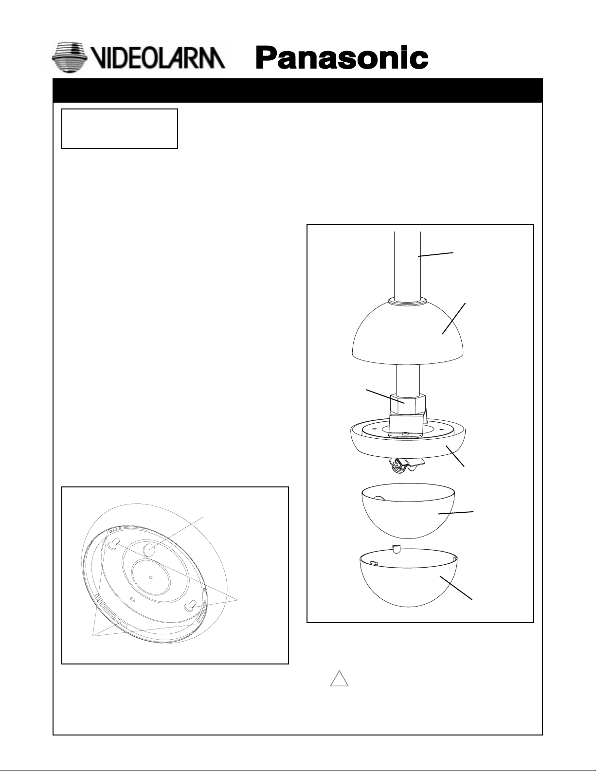
ATTACHING HOUSING (PCF6/PCV6 PENDANT MOUNT)
1. Install 3/4" EMT pipe (not provided) to the desired length.
2. Slide the top dome 10" to 12" onto the pipe, leaving enough
room to work. Run the wiring through the EMT connector
and wiring hole inside the top of the housing.
3. Slide complete unit onto the pipe. Tighten the set screw
when
in place.
4. Once the housing is secured to the pipe, slide the top dome
down onto the top of the housing.
3/4" EMT Pipe
(not provided)
Top Dome
EMT Clamp
Connector
Housing
Dome Tab Slots
Dome Tab Slots
Wire or Cable Entry
Wire or Cable Entry
Key Hole
Key Hole Slots
Slots
Liner
Dome
NOTE: Once the housing has been attached to the desired
location, connect the power and video wires as
required.
Connect Class 2 power supply only!
!
Page 2
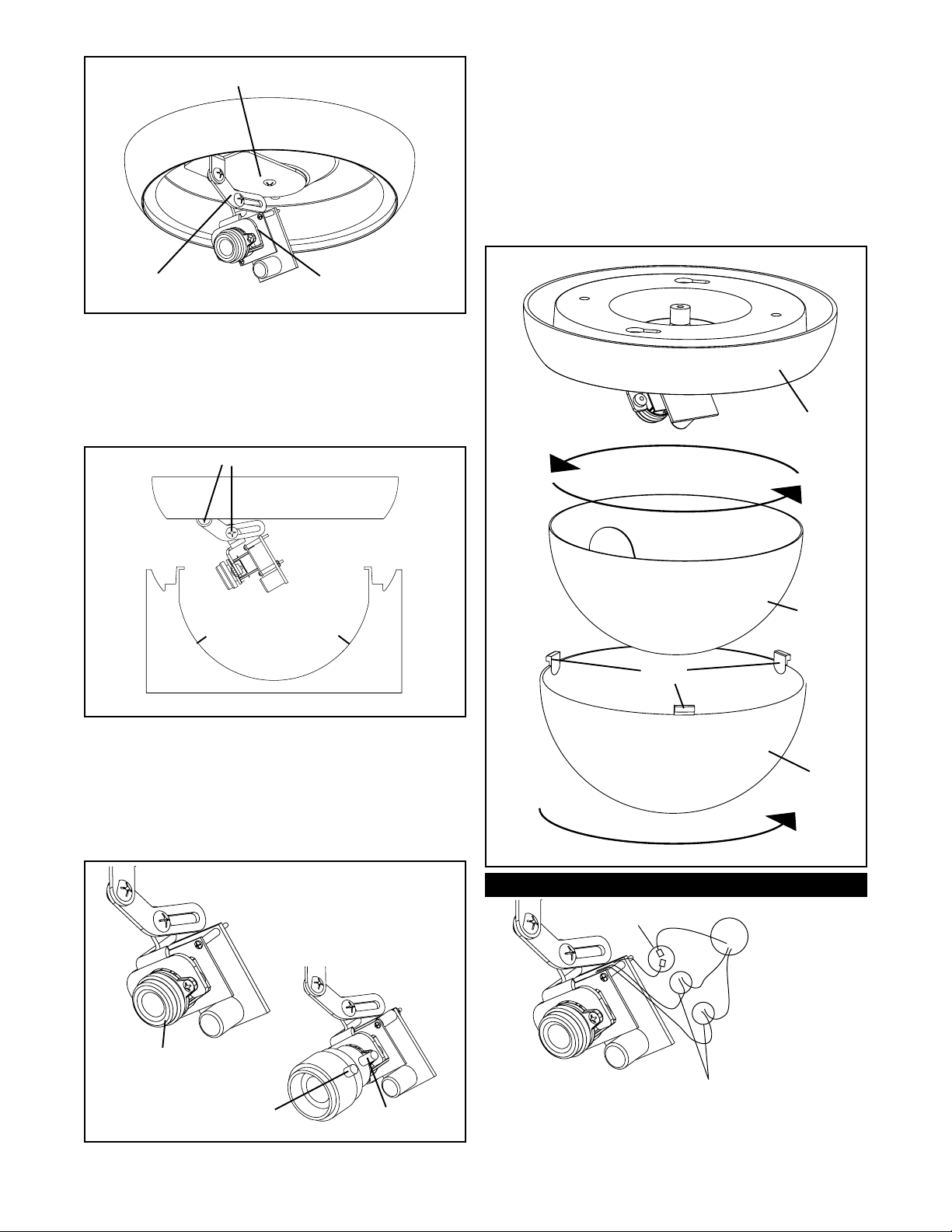
Camera swivel plate
DOME REPLACEMENT
1. Rotate the liner inside the dome, so that when the dome is
secured to the base, the camera lens is in the center of the
viewing slot of the liner.
NOTE: It may be helpful to install the dome without the liner
the first time. This way you can visually determine
which direction the lens is pointing and adjust the liner
opening accordingly.
2. Align and insert the three tabs of the dome with the three tab
slots on the dome base. Rotate the dome clockwise until the
dome locks into place.
Camera Adjustment
Arm
CAMERA ADJUSTMENT
1. Clip the tabs of the template onto the swivel plate so that the
template is attached to the swivel plate.
2. Loosen the two 4-40 Phillips head screws, adjust the camera to
the desired position, and tighten the screws.
Note: Adjust camera lens as close as possible to the outline of
the bottom of the template.
Loosen screws to adjust camera
Tab
Place the lens as close to
this edge as possible
Camera Adjustment Template
3. Fine focusing (see diagram below):
Fixed Lens: Manually rotate the lens until a clear picture is
achieved.
Vari-Focal Lens: First, adjust the Magnification Lock Screw
to the desired magnification (telephoto
to wide angle). Tighten the Lock Screw.
Next, adjust the Focus Lock Screw until a
clear picture is achieved. Tighten the
Lock Screw.
Fixed Lens Camera
(PCF2, PCF6)
Camera Mount with
Camera and PC Board
Tab
Base
Liner
Tabs
Dome
Connections
Video
BNC Connectors
Manual focus
Focus Lock Screw
Vari-Focal Lens Camera
(PCV2, PCV6)
Magnification
Lock Screw
Power Connections
NOTE: Splice wiring according to
standard electrical guidlines.
Positive and Negative connections are
interchangeable with this PC Board.
- 2 -
Page 3

PCF2, PCV2 Dimensions
PCF6, PCV6 Dimensions
Specification
Lens Type
Model Number
Scanning Area
Scanning
Horizontal
Vertical
Synchronization
Video Output
Horizontal Resolution
Signal-to-Noise Ratio
Minimum Illumination
Angular Field of View
Horizontal
Vertical
AGC
ELC
White Balance
Ambient Operating
Temperature
Ambient Operating
Humidity
Power Source
at AC Source
at DC Source
Dimensions
Weight
6.0" Dia.
5.0" Dia.
6.0"
1.0"
5.0"
3 - 8mm Fixed Focal Lens Series 4 - 8mm Vari- -Focal Lens Series
PCF1 PCF6WPCF6PCF5PCF4PCF3PCF2 PCV6WPCV6PCV5PCV4PCV3PCV2PCV1
361 mm (H) x 272 mm (V) (Equivalent to scanning area of 1/4" pick-up tube)
525 lines / 60 fields / 30 frames
15.734 kHz
59.94 kHz
Internal Synchronization
1.0 V (p-p) NTSC Composite 75 ohms / BNC Connector
330 lines (at center area)
46 dB (with AGC OFF)
0.5 Footcandle (5 Lux) at F2.0 0.5 Footcandle (5 Lux) at F2.0 - 1.0 Footcandle
Horizontal 53.4˚
Vertical 40.0˚ Vertical 38.4 - 20.0˚
On (Preset)
On (Preset)
ATW (Preset)
-10˚C - +50˚C (14˚F - 122˚F)
Less than 90%
24 VAC, 40 ma
12 VDC, 80 ma
2.82"
W
H
D
kg
lbs
4.6"
2.82"
0.68
1.5
6.0"
6.0"
6.0"
0.45
1
3.15"
4.9"
3.2"
0.45
1
5.25"
3.0"
3.625"
0.45
1
15.9"
11.2"
15.9"
1.8
4
6.0"
6.0"
6.0"
0.68
1.5
6.0"
10.8"
7.0"
0.91
2
6.0"
5.75"
(10 Lux) at F2.8
Horizontal 51.7 - 26.7˚
2.82"
6.0"
3.15"
5.25"
4.6"
2.82"
0.68
1.5
6.0"
6.0"
0.45
1
4.9"
3.2"
0.45
1
3.0"
3.625"
0.45
1
15.9"
11.2"
15.9"
1.8
4
6.0"
6.0"
6.0"
0.68
1.5
6.0"
10.8"
7.0"
0.91
2
CAUTION: To prevent fire or shock hazard, the UL-Listed wire
VW-1, style 1007, should be used for the cable for
24 VAC input terminals.
Wiring Chart-Cable Distance
This Chart is based on a 12VDC power supply with the
maximum Amp draw at .500 amps.
WIRE 20 18 16
FT. 180' 300' 480'
- 3 -
Page 4

STANDARD INSTALLATION PROCEDURE, MV6W
CONTENTS INCLUDE:
(1) Wall mount Bracket
(1) Dome base
(1) Dome
(1) Dome liner
(1) Camera swivel plate
(1) Camera mount with camera, lens, and PC Board
(1) Camera adjustment arm
(1) Camera adjustment template
(2) 4-40 x 1/4" screws
(1) 8-32 x 3/8" screw
INSTALLATION
1. Locate the area on the wall where the bracket is to be
mounted. Cut a hole no larger than 1" in diameter and
feed the necessary wires/cable through (Figure 1).
2. Feed wires/cable through the hole in the back side of the
bracket and out through end of the pipe.
3. Attach the bracket to the wall with fasteners that best fit
the application.
2. Once the top dome has been placed on the bracket, feed all
wires/cable through the 3/4" conduit connector and camera
housing.
3. Slide the housing onto the bracket, then tighten down the screw
on the 3/4" conduit connector (Figure 3).
Note: The connector will need to be tightened completly
down to secure the housing to bracket.
4. Once the housing has been secured to the bracket, slide
the top dome back down along the bracket until it fits on
top of the housing. The grommet will keep the top dome in
place.
3/4" CONDUIT CONNECTOR
Figure 3
Make necessary camera adjustments and complete the
installation process as specified elsewhere in these instructions.
Figure 1
HOUSING INSTALLATION
1. Once the bracket is secure, feed all wires/cable through
the top dome. Slide the top dome onto the bottom of
the bracket; the grommet should be secure around the
bracket pipe (Figure 2).
GROMMET
TOP DOME
Figure 2
PCF6W, PCV6W Dimensions
3.4"
3.3"
10.8"
7.0"
5.4"
- 4 -
Page 5

1. Read Instructions - All the safety and operating instructions
!
should be read before the unit is operated.
2. Retain Instructions - The safety and operating instructions
should be retained for future reference.
3. Heed Warnings - All warnings on the unit and in the
operating instructions should be adhered to.
4. Follow Instructions - All operating and user instructions
should be followed.
5. Electrical Connections - Only a qualified electrician should
make electrical connections.
6. Attachments - Do not use attachments not recommended
by the product manufacturer as they may cause hazards.
7. Cable Runs - All cable runs must be within permissible
distance.
8. Mounting - This unit must be properly and securely mounted
to a supporting structure capable of sustaining the weight
of the unit. Accordingly:
a. The installation should be made by a qualified service
person, and should conform to all local codes.
b. Care should be exercised to select suitable hardware
to install the unit, taking into account both the
composition of the mounting surface and the weight of
the unit. Be sure to periodically examine the unit and the
supporting structure to make sure that the integrity of the
installation is intact. Failure to comply with the foregoing
could result in the unit separating from the support
structure and falling, with resultant damages or injury to
anyone or anything struck by the falling unit.
SAFETY PRECAUTIONSIMPORTANT SAFEGUARDS
CAUTION
RISK OF
ELECTRIC SHOCK!
CAUTION: TO REDUCE THE RISK OF
ELECTRICAL SHOCK, DO NOT EXPOSE
COMPONENTS TO WATER OR MOISTURE.
The lightning flash with an arrowhead symbol,
within an equilateral triangle, is intended to
alert the user to the presence of non-insulated
"dangerous voltage" within the product's
enclosure that may be of sufficient magnitude
to constitute a risk of electric shock to persons.
The exclamation point within an equilateral
triangle is intended to alert the user to
!
UNPACKING
Unpack carefully. Electronic components can be
damaged if improperly handled or dropped. If an item
appears to have been damaged in shipment, replace it
properly in its carton and notify the shipper.
presence of important operating and
maintenance (servicing) instructions in the
literature accompanying the appliance.
Be sure to save:
1. The shipping carton and packaging material. They are the
safest material in which to make future shipments of the
equipment.
2. These Installation and Operating Instructions.
SERVICE
For service on Panasonic/Videolarm equipment contact:
Panasonic Technical Center
54 West Gude Dr.
Rockville MD 20850-1150
Phone: 301-762-5125
Fax: 301-251-0347
PANASONIC TECHNICAL SUPPORT
1-800-528-6747
9:00 AM - 5:00 PM EASTERN TIME
- 5 -
 Loading...