

Panasonic Pcv3, Pcf3 Operating Instructions
Manufactured by:
81-IN3048-9922
Before attempting to connect or operate this product, please read these instructions completely.
for
MODEL: Miniature Camera
PCF3, PCV3
DESCRIPTION: Recessed Wall Housing, Color Camera
STANDARD INSTALLATION PROCEDURE
INCLUDES MODELS: PCF3, PCV3
Remove equipment from box, contents include:
CONTENTS INCLUDE:
(1) Flush Mount Box
(1) Cover plate with window
(2) Allen wrench security head tool
(2) Stainless steel 6-32x1/2" captive Security head screws
(1) Camera mount bracket
(1) Camera mount arm
(1) Bottom mount bracket
(2) 4-40 x 1/4" screws
(2) Star washers
(2) 2-56 x 3/16" Screws
(1) Camera, lens, and PC Board
PRODUCT INSTRUCTIONS
6. Remove the top mount bracket. This will allow you to
remove the camera/PC Board assembly from the unit.
7. Once you have removed the camera assembly, make
the necessary connections to the PC Board.
USE CLASS 2 POWER ONLY
!
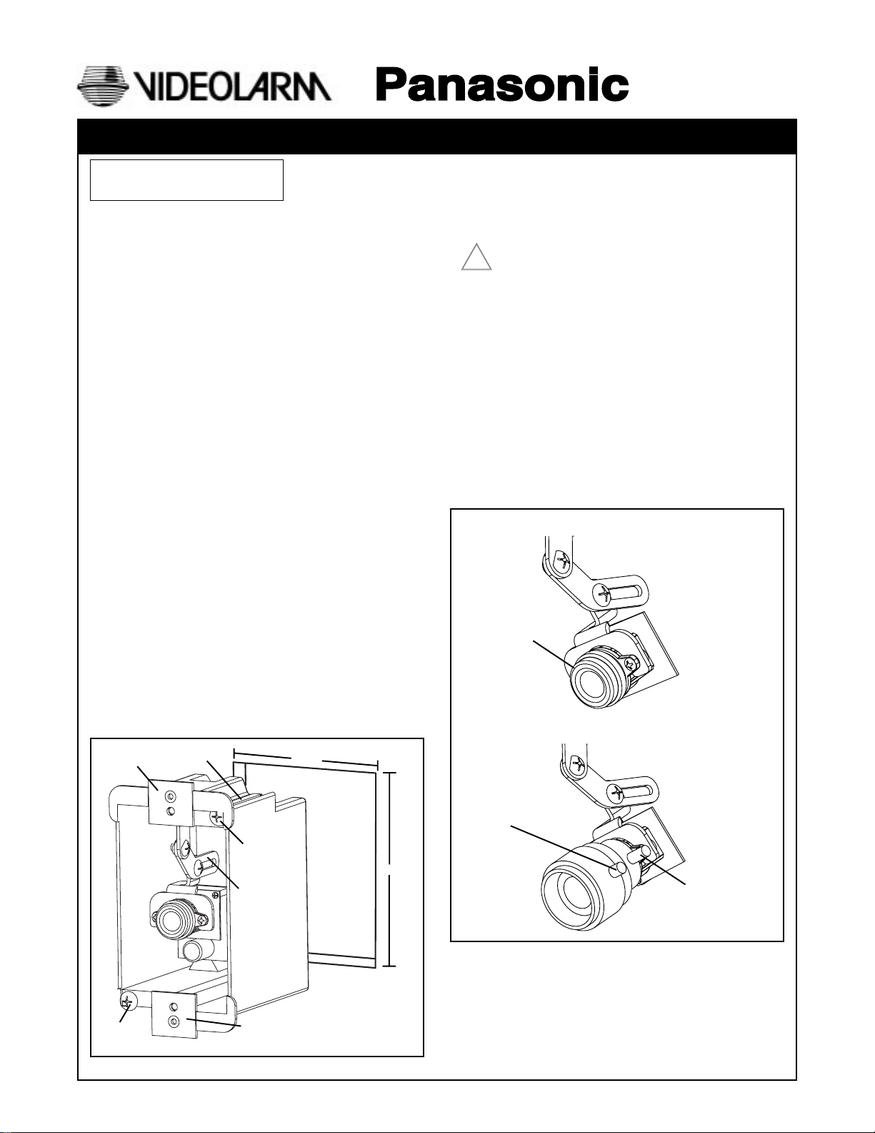
5. Hand place the top mount bracket and camera into the
unit. Check the angle of the camera, remove the
bracket/camera and make any necessary adjustments.
Once you have achieved the desired camera angle,
reattach the top bracket and camera to the housing.
Fine focusing can be achieved by manually rotating the
lens.
6. Fine focusing (see diagram below):
Fixed Lens: Manually rotate the lens until a clear picture is
achieved.
Vari-Focal Lens: First, adjust the Magnification Lock Screw
to the desired magnification (telephoto
to wide angle). Tighten the Lock Screw.
Next, adjust the Focus Lock Screw until a
clear picture is achieved. Tighten the
Lock Screw.
Camera Fine Focus
1. Locate the area on the wall where the housing will be
installed and cut a 2 1/4" x 3 3/4" hole into the wall.
2. Run the necessary wiring/cables to this cutout and pull
wiring/cables through opening.
3. Using the security tool, loosen the 2 security head
screws on the cover plate and remove it.
4. Feed the wiring/cables through one or more of the
cable entry holes in the back of the flush mount box.
5. Install the housing into the cutout in the wall and
tighten the Phillips head screws on the front of the
box. This will pull the lock tabs forward to secure
the box to the wall.
Top Mount
Bracket
Lock Tab
2 1/4"
Lock Tab
Screw
Camera
Mount Arm
Cut Out
3 3/4"
Fixed Lens Camera
PCF3
Manual focus
Vari-focal Lens Camera
PCV3
Focus Lock Screw
Magnification
Lock Screw
Lock Tab
Screw
Bottom Mount
Bracket
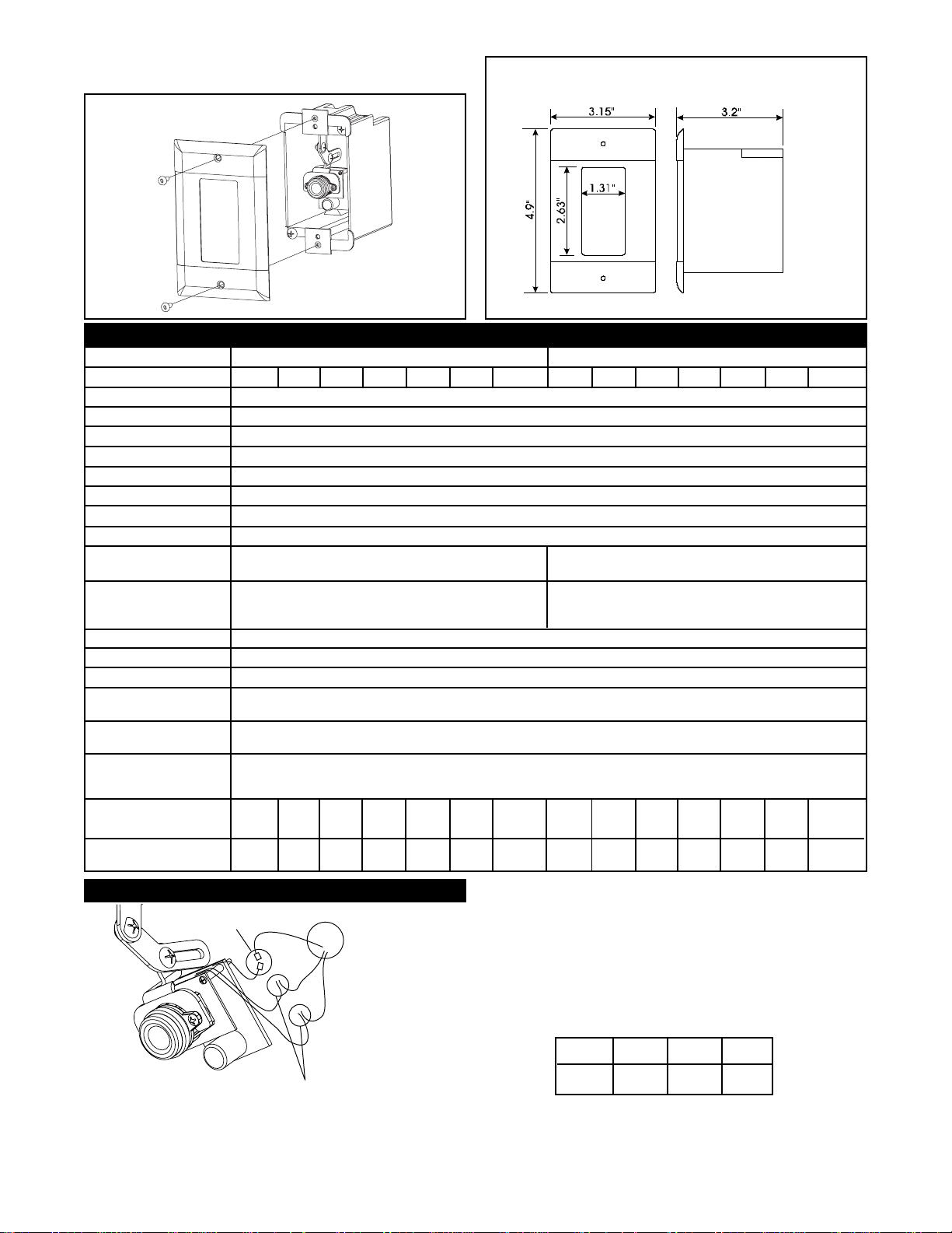
6. Replace the cover on the housing and reattach using the
2 security screws.
Specification
Lens Type
Model Number
Scanning Area
Scanning
Horizontal
Vertical
Synchronization
Video Output
Horizontal Resolution
Signal-to-Noise Ratio
Minimum Illumination
Angular Field of View
Horizontal
Vertical
AGC
ELC
White Balance
Ambient Operating
Temperature
Ambient Operating
Humidity
Power Source
at AC Source
at DC Source
Dimensions
Weight
W
H
D
kg
lbs
2.82"
4.6"
2.82"
0.68
1.5
3 - 8mm Fixed Focal Lens Series 4 - 8mm Vari- -Focal Lens Series
PCF1
PCF3PCF2
PCF4
PCF5
361 mm (H) x 272 mm (V) (Equivalent to scanning area of 1/4" pick-up tube)
525 lines / 60 fields / 30 frames
Internal Synchronization
1.0 V (p-p) NTSC Composite 75 ohms / BNC Connector
330 lines (at center area)
46 dB (with AGC OFF)
0.5 Footcandle (5 Lux) at F2.0 0.5 Footcandle (5 Lux) at F2.0 - 1.0 Footcandle
Horizontal 53.4˚
Vertical 40.0˚ Vertical 38.4 - 20.0˚
3.15"
5.25"
6.0"
6.0"
6.0"
0.45
1
4.9"
3.2"
0.45
1
3.0"
3.625"
0.45
1
15.9"
11.2"
15.9"
1.8
4
Dimensions for the PCF3/PCV3 (not to scale)
PCF6W
PCF6
15.734 kHz
59.94 kHz
(10 Lux) at F2.8
On (Preset)
On (Preset)
ATW (Preset)
-10˚C - +50˚C (14˚F - 122˚F)
Less than 90%
24 VAC, 40 ma
12 VDC, 80 ma
6.0"
6.0"
6.0"
0.68
1.5
6.0"
10.8"
7.0"
0.91
2
2.82"
4.6"
2.82"
0.68
1.5
PCV2PCV1
PCV3
Horizontal 51.7 - 26.7˚
6.0"
3.15"
6.0"
4.9"
6.0"
3.2"
0.45
0.45
1
1
PCV4
5.25"
3.0"
3.625"
0.45
1
PCV5
15.9"
11.2"
15.9"
1.8
4
PCV6
6.0"
6.0"
6.0"
0.68
1.5
PCV6W
6.0"
10.8"
7.0"
0.91
2
Connections
Video
BNC Connectors
Power Connections
NOTE: Splice wiring according to
standard electrical guidlines.
Positive and Negative connections are
interchangeable with this PC Board.
CAUTION: To prevent fire or shock hazard, the UL-Listed wire
VW-1, style 1007, should be used for the cable for
24 VAC input terminals.
Wiring Chart-Cable Distance
This Chart is based on a 12VDC power supply with the
maximum Amp draw at .500 amps.
WIRE 20 18 16
FT. 180' 300' 480'
- 2 -
 Loading...