

Page 1
Manufactured by:
81-IN3046-9922
Before attempting to connect or operate this product, please read these instructions completely.
for
MODEL: Miniature Camera
PCF1, PCV1
DESCRIPTION: Outdoor Pedestal Mount Housing,
Color Camera
STANDARD INSTALLATION PROCEDURE
INCLUDES MODELS: PCF1, PCV1
CONTENTS INCLUDE:
(1) Housing
(1) Weather hood
(1) Cover plate
(1) Cover plate gasket
(1) Allen wrench security head tool
(2) Stainless steel 6-32x1/2" captive Security head screws
(1) Camera mount bracket
(1) Camera bracket arm
(1) Bottom mount bracket with PC Board
(1) Top mount bracket with camera and lens
(2) 4-40 x 1/4" screws
(2) Star washers
(4) 2-56 x 3/16" screws
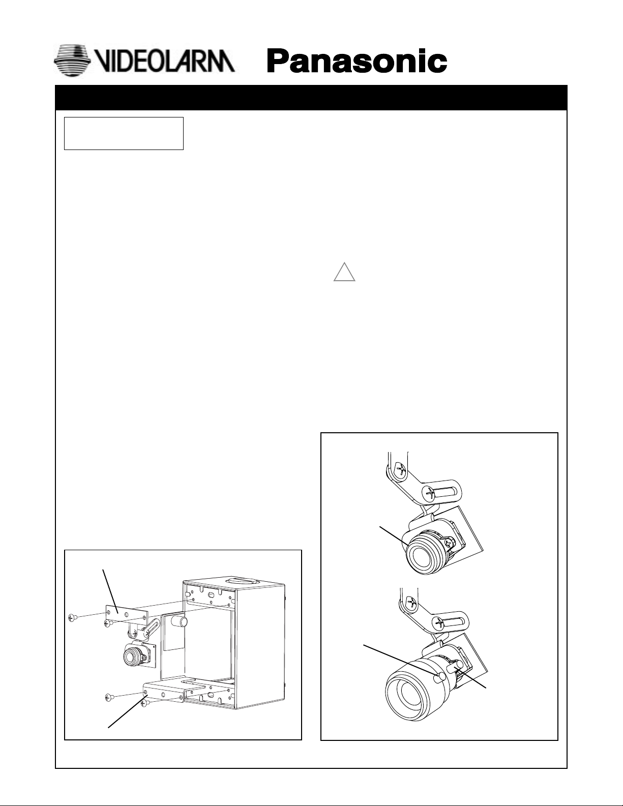
1. Remove the cover plate by loosening the 2 security head
screws with the security tool.
2. If mounting the unit to a wall:
A. Remove the 2 Phillips head screws that secure the
bottom mount bracket and PC Board to the housing,
then remove the bracket. Repeat for the top mount
bracket and camera.
B. Place the housing face down on a flat surface and use
a hammer to remove the knockout located at the
center of the back of the housing.
C. Use the 2 mounting holes and the appropriate
hardware (not included)to secure the housing to the
wall.
PRODUCT INSTRUCTIONS
3. If mounting the unit on a pedestal:
NOTE: 3/4" conduit with a threaded end is required for this
method of installation.
A. Install the conduit in the desired location; run the
wiring through the conduit.
B. Place the PFC1/PCV1 housing onto the conduit, feed
the wires through the bottom hole and thread the
housing onto the conduit until tight.
N NOTE: Apply silicone sealant to the conduit threads and
the hole plug to ensure a water tight seal.
4. Make the necessary connections to the PC Board and
reattach the bottom bracket to the housing.
USE CLASS 2 POWER ONLY
!
5. Hand place the top bracket and camera into the unit.
Check the angle of the camera, remove the bracket/
camera and make any necessary adjustments. Once
you have achieved the desired camera angle, reattach
the top bracket and camera to the housing.
6. Fine focusing (see diagram below):
Fixed Lens: Manually rotate the lens until a clear picture is
achieved.
Vari-Focal Lens: First, adjust the Magnification Lock Screw
to the desired magnification (telephoto
to wide angle). Tighten the Lock Screw.
Next, adjust the Focus Lock Screw until a
clear picture is achieved. Tighten the
Lock Screw.
Camera Fine Focus
Fixed Lens Camera
(PCF1)
Manual focus
Top mount bracket and camera
Bottom mount bracket and PC Board
Vari-focal Lens Camera
(PCV1)
Focus Lock Screw
Magnification
Lock Screw
Page 2
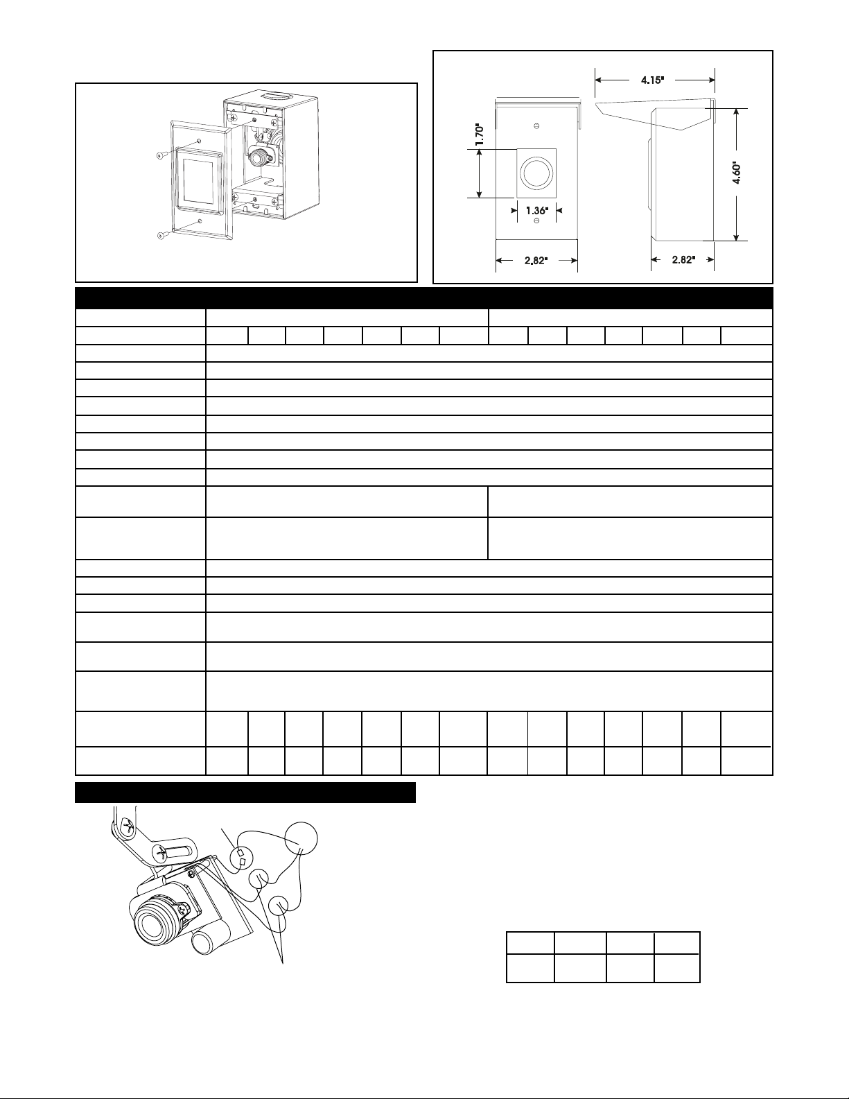
6. Replace the cover on the housing and reattach using the
2 security screws.
Specification
Lens Type
Model Number
Scanning Area
Scanning
Horizontal
Vertical
Synchronization
Video Output
Horizontal Resolution
Signal-to-Noise Ratio
Minimum Illumination
Angular Field of View
Horizontal
Vertical
AGC
ELC
White Balance
Ambient Operating
Temperature
Ambient Operating
Humidity
Power Source
at AC Source
at DC Source
Dimensions
Weight
Connections
2.82"
W
4.6"
H
2.82"
D
0.68
kg
1.5
lbs
Video
BNC Connectors
3 - 8mm Fixed Focal Lens Series 4 - 8mm Vari- -Focal Lens Series
PCF1
PCF3PCF2
PCF4
PCF5
361 mm (H) x 272 mm (V) (Equivalent to scanning area of 1/4" pick-up tube)
525 lines / 60 fields / 30 frames
Internal Synchronization
1.0 V (p-p) NTSC Composite 75 ohms / BNC Connector
330 lines (at center area)
46 dB (with AGC OFF)
0.5 Footcandle (5 Lux) at F2.0 0.5 Footcandle (5 Lux) at F2.0 - 1.0 Footcandle
Horizontal 53.4˚
Vertical 40.0˚ Vertical 38.4 - 20.0˚
3.15"
5.25"
6.0"
6.0"
6.0"
0.45
1
4.9"
3.2"
0.45
1
3.0"
3.625"
0.45
1
15.9"
11.2"
15.9"
1.8
4
Dimensions for the PCF1/PCV1 (not to scale)
PCF6W
PCF6
15.734 kHz
59.94 kHz
(10 Lux) at F2.8
On (Preset)
On (Preset)
ATW (Preset)
-10˚C - +50˚C (14˚F - 122˚F)
Less than 90%
24 VAC, 40 ma
12 VDC, 80 ma
6.0"
6.0"
6.0"
0.68
1.5
6.0"
10.8"
7.0"
0.91
2
2.82"
4.6"
2.82"
0.68
1.5
CAUTION: To prevent fire or shock hazard, the UL-Listed
wire VW-1, style 1007, should be used for the
cable for 24 VAC input terminals.
PCV2PCV1
PCV3
Horizontal 51.7 - 26.7˚
6.0"
3.15"
6.0"
4.9"
6.0"
3.2"
0.45
0.45
1
1
PCV4
5.25"
3.0"
3.625"
0.45
1
PCV5
15.9"
11.2"
15.9"
1.8
4
PCV6
6.0"
6.0"
6.0"
0.68
1.5
PCV6W
6.0"
10.8"
7.0"
0.91
2
Power Connections
NOTE: Splice wiring according to
standard electrical guidlines.
Positive and Negative connections are
interchangeable with this PC Board.
Wiring Chart-Cable Distance
This Chart is based on a 12VDC power supply with the
maximum Amp draw at .500 amps.
WIRE 20 18 16
FT. 180' 300' 480'
- 2 -
Page 3

1. Read Instructions - All the safety and operating instructions
!
should be read before the unit is operated.
2. Retain Instructions - The safety and operating instructions
should be retained for future reference.
3. Heed Warnings - All warnings on the unit and in the
operating instructions should be adhered to.
4. Follow Instructions - All operating and user instructions
should be followed.
5. Electrical Connections - Only a qualified electrician should
make electrical connections.
6. Attachments - Do not use attachments not recommended
by the product manufacturer as they may cause hazards.
7. Cable Runs - All cable runs must be within permissible
distance.
8. Mounting - This unit must be properly and securely mounted
to a supporting structure capable of sustaining the weight
of the unit. Accordingly:
a. The installation should be made by a qualified service
person, and should conform to all local codes.
b. Care should be exercised to select suitable hardware
to install the unit, taking into account both the
composition of the mounting surface and the weight of
the unit. Be sure to periodically examine the unit and the
supporting structure to make sure that the integrity of the
installation is intact. Failure to comply with the foregoing
could result in the unit separating from the support
structure and falling, with resultant damages or injury to
anyone or anything struck by the falling unit.
SAFETY PRECAUTIONSIMPORTANT SAFEGUARDS
CAUTION
RISK OF
ELECTRIC SHOCK!
CAUTION: TO REDUCE THE RISK OF
ELECTRICAL SHOCK, DO NOT EXPOSE
COMPONENTS TO WATER OR MOISTURE.
The lightning flash with an arrowhead symbol,
within an equilateral triangle, is intended to
alert the user to the presence of non-insulated
"dangerous voltage" within the product's
enclosure that may be of sufficient magnitude
to constitute a risk of electric shock to persons.
The exclamation point within an equilateral
triangle is intended to alert the user to
!
UNPACKING
Unpack carefully. Electronic components can be
damaged if improperly handled or dropped. If an item
appears to have been damaged in shipment, replace it
properly in its carton and notify the shipper.
presence of important operating and
maintenance (servicing) instructions in the
literature accompanying the appliance.
Be sure to save:
1. The shipping carton and packaging material. They are the
safest material in which to make future shipments of the
equipment.
2. These Installation and Operating Instructions.
SERVICE
For service on Panasonic/Videolarm equipment contact:
Panasonic Technical Center
54 West Gude Dr.
Rockville MD 20850-1150
Phone: 301-762-5125
Fax: 301-251-0347
PANASONIC TECHNICAL SUPPORT
1-800-528-6747
9:00 AM - 5:00 PM EASTERN TIME
- 3 -
 Loading...