

Page 1
Manufactured by:
81-IN3064-9922
Before attempting to connect or operate this product, please read these instructions completely.
for
MODEL: PC9
Indoor Wall Mount Housing
Installation Preparation
1. Determine the mounting location. Be sure that you'll be
mounting to a secure wall or ceiling, next to a stud.
2. Complete all wire and conduit runs prior to installation of
the housing.
Installation Procedure
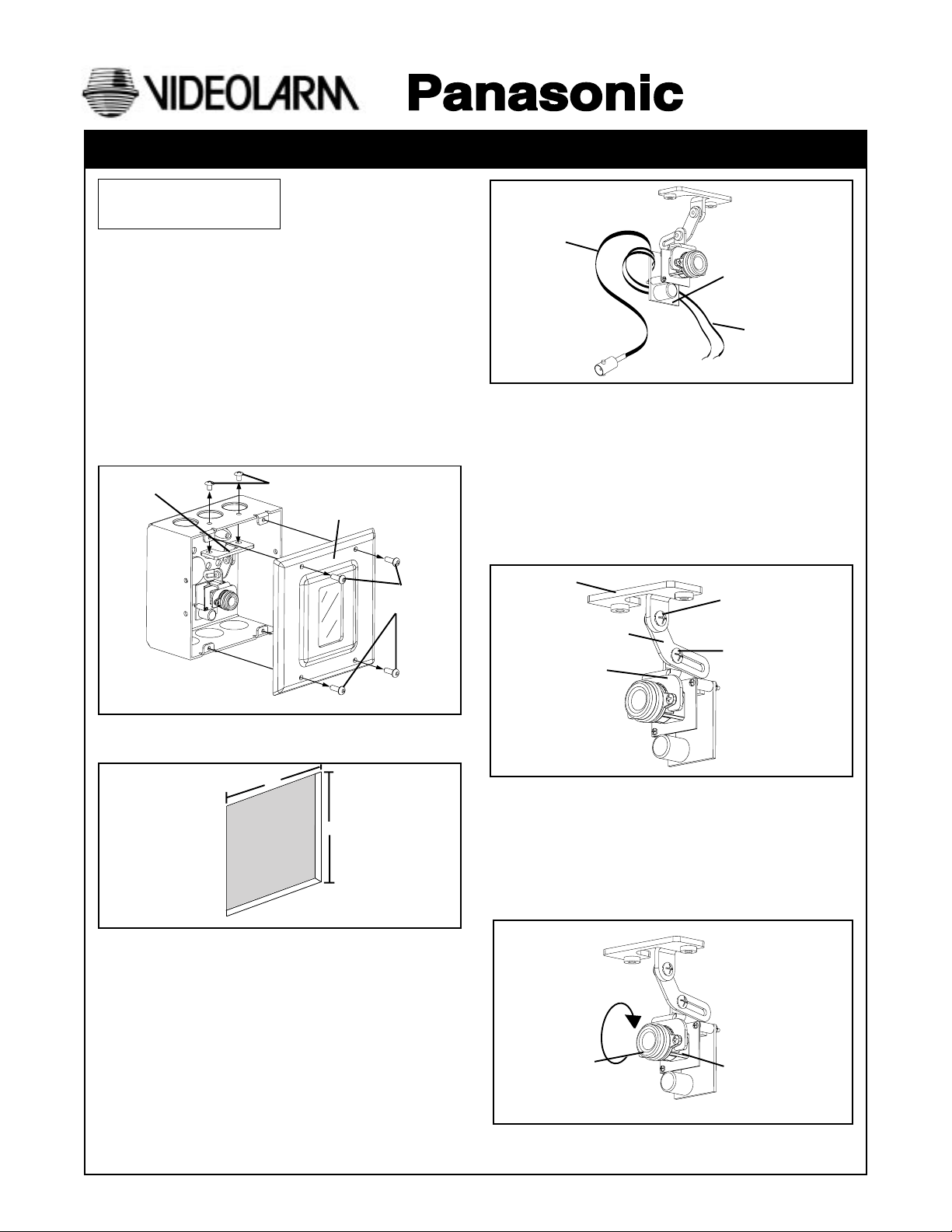
1. Using the security tool provided, loosen the (4) 8-32
security fasteners and remove the housing top (Figure 1).
2. Loosen the (2) 10-32 screws holding the top camera
bracket and camera in place (Figure 1).
Top Camera
Bracket
10-32 Screws
Housing Top
PRODUCT INSTRUCTIONS
Video Cable
PC Board
Power wires
Figure 3
7. Check the position of the camera by placing the top
bracket and camera in position against the top of the
housing and finger holding. Move the front plate into
position against the box with your other hand and
"eyeball" whether the bracket is too low or high for the
window.
8. Use the 6-32 screw at the top of the bracket adjustment
arm to raise or lower the camera. Use the 6-32 screw
holding the camera bracket to the camera adjustment
arm to adjust the angle of the camera (Figure 4).
8-32 Security
Screws
Figure 1
3. Cut a 4 3/4" x 4 3/4" square hole in the surface with one
side against the stud (Figure 2).
4 3/4"
4 3/4"
Cutout
Wall
Figure 2
4. Determine which side the conduit outlet will be located
on: Top, bottom, left, or right. Remove the desired
conduit knockout.
5. Position the double-gang box in the cutout against the
stud. Mark the location of the two mounting holes on the
box side and remove the box.
6. Feed the power and video wires through the conduit
knockout hole in the box. Connect the incoming 12 VDC
or 24 VAC power to the PC board using the wire leads
from the board. Connect the video cable from the wire
harness on the PC board to the incoming video
(Figure 3).
Top Camera
Bracket
Bracket Adjustment
Arm
Camera Bracket
Figure 4
9. Once the proper viewing angle has been set, reattach
the top bracket and camera to the double-gang box
using the (2) 10-32 screws.
10. Mount the double-gang box to the stud using (2)
self-tapping 10-32 screws (not provided).
11. Adjust the fine focusing of the fixed lens (Figure 5).
Camera Lens
Figure 5
Top 6-32 Screw
Lower 6-32 Screw
Camera
Page 2
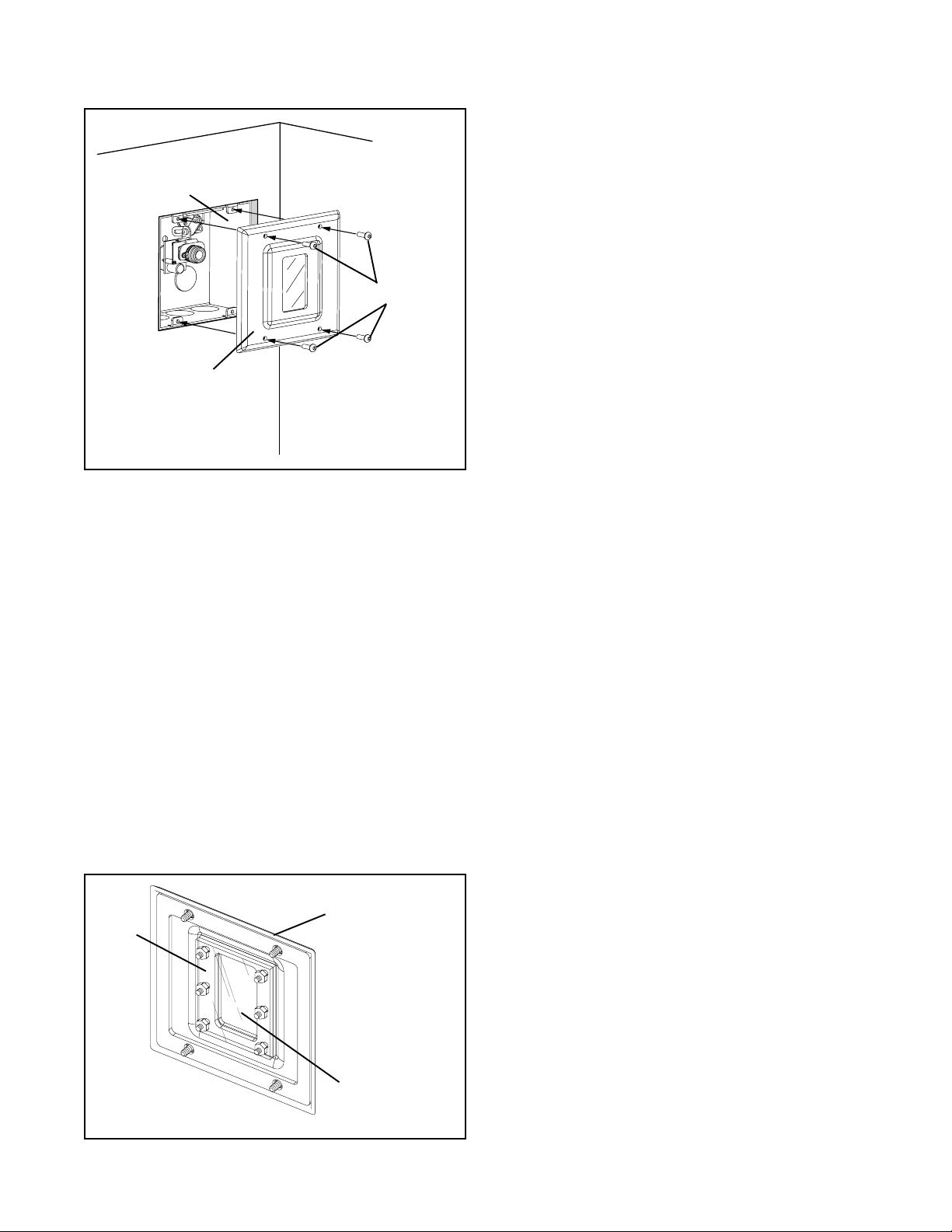
12. Reattach the front plate to the double-gang box and
tightly fasten the (4) security screws using the security tool
(Figure 6).
Double-gang box
fixed in wall cutout
8-32 Security
Screws
Front Plate
Figure 6
NOTE: If, after installing the front plate, you discover that the
lens of the camera is touching the front plate window,
remove the plate and readjust the camera bracket. To
readjust, use the top 6-32 screw (See Figure 4).
WindowGuard™ Replacement
Your PC9 comes with a WindowGuard™ shield to protect the
front plate window from vandalism. If vandalism occurs (spray
paint, scratches, etc.) you need only replace the shield, not
the entire window. To replace the shield, use the following
directions.
1. Remove the face plate.
2. On the inside of the face plate, remove the (6) 6-32 nuts
holding the window in place (Figure 7).
3. Peel off the damaged paint shield.
4. Place a new shield on the window, reinstall the window, and
reinstall the face plate.
NOTE: Two replacement shields are included with your unit.
Additional shields can be ordered from the manufac turer.
Front Plate
Gasket
Figure 7
Window and
Replacement Shield
- 2 -
Page 3

1. Read Instructions - All the safety and operating instructions
!
should be read before the unit is operated.
2. Retain Instructions - The safety and operating instructions
should be retained for future reference.
3. Heed Warnings - All warnings on the unit and in the operating
instructions should be adhered to.
4. Follow Instructions - All operating and user instructions should
be followed.
5. Electrical Connections - Only a qualified electrician should
make electrical connections.
6. Attachments - Do not use attachments not recommended by the
product manufacturer as they may cause hazards.
7. Cable Runs - All cable runs must be within permissible distance.
8. Mounting - This unit must be properly and securely mounted to
a supporting structure capable of sustaining the weight of the
unit. Accordingly:
a. The installation should be made by a qualified service
person, and should conform to all local codes.
b. Care should be exercised to select suitable hardware to
install the unit, taking into account both the composition of the
mounting surface and the weight of the unit. Be sure to
periodically examine the unit and the supporting structure to
make sure that the integrity of the installation is intact. Failure
to comply with the foregoing could result in the unit separating
from the support structure and falling, with resultant damages
or injury to anyone or anything struck by the falling unit.
SAFETY PRECAUTIONSIMPORTANT SAFEGUARDS
CAUTION
RISK OF
ELECTRIC SHOCK!
CAUTION: TO REDUCE THE RISK OF
ELECTRICAL SHOCK, DO NOT EXPOSE
COMPONENTS TO WATER OR MOISTURE.
The lightning flash with an arrowhead symbol,
within an equilateral triangle, is intended to
alert the user to the presence of non-insulated
"dangerous voltage" within the product's
enclosure that may be of sufficient magnitude
to constitute a risk of electric shock to persons.
The exclamation point within an equilateral
triangle is intended to alert the user to
!
UNPACKING
Unpack carefully. Electronic components can be
damaged if improperly handled or dropped. If an item
appears to have been damaged in shipment, replace it
properly in its carton and notify the shipper.
presence of important operating and
maintenance (servicing) instructions in the
literature accompanying the appliance.
Be sure to save:
1. The shipping carton and packaging material. They are the
safest material in which to make future shipments of the
equipment.
2. These Installation and Operating Instructions.
SERVICE
For service on Panasonic/Videolarm equipment contact:
Panasonic Technical Center
54 West Gude Dr.
Rockville MD 20850-1150
Phone: 301-762-5125
Fax: 301-251-0347
PANASONIC TECHNICAL SUPPORT
1-800-528-6747
9:00 AM - 5:00 PM EASTERN TIME
- 3 -
 Loading...