

Page 1
Manufactured by:
81-IN3059-9922
Before attempting to connect or operate this product, please read these instructions completely.
for
MODEL: PC7
Indoor wall/ceiling housing
Installation Preparation
1. Determine the mounting location. Be sure that you'll be
mounting to a secure wall or ceiling.
2. Complete all wire and conduit runs prior to installation of
the housing.
3. Determine the mounting method:
A. Mount directly to a wall or ceiling.
B. Mount to a standard 4-square electrical box (not
provided).
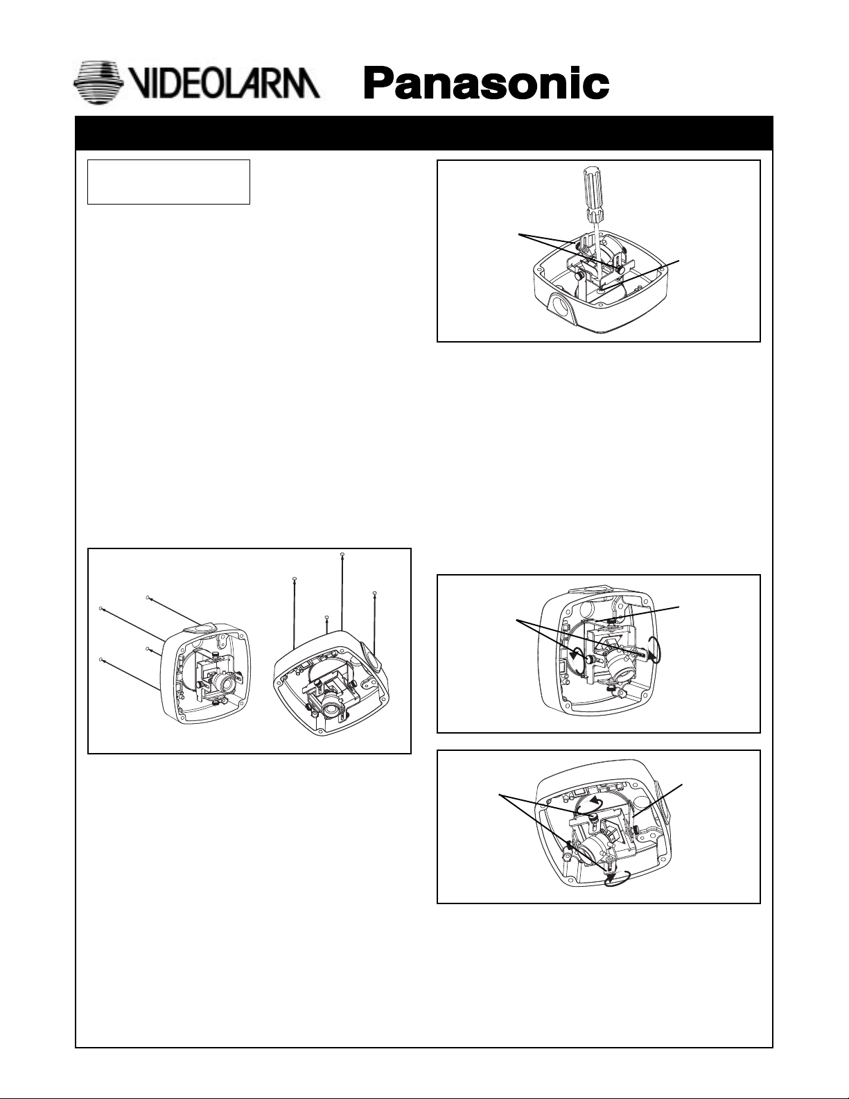
Installation Procedure
1. Using the security tool provided, loosen the four security
fasteners and remove the housing top.
2. Determine which side the conduit outlet will be located
on: Top, bottom, left, or right.
3. Position the housing in the desired location and mark the
four mounting holes (for wall mount, use Figure 1, for
ceiling mount use Figure 2).
PRODUCT INSTRUCTIONS
Thumb screws
Figure 3
Bracket Alignment:
Wall mount: Be sure the rotating bracket is positioned
vertically (Figure 4).
Ceiling mount: Be sure the rotating bracket is aligned to
point toward the desired viewing
location (Figure 5).
NOTE: The wiring harness on the top of the camera
should always be oriented at what would be
considered the top of the housing. This will keep
the camera oriented for proper viewing. For
example, if the housing is rotated 90˚ to the left to
accommodate a conduit, the rotating housing
bracket must be turned back 90˚ to the right. In
ceiling applications, if the harness is on the
bottom, simply flip the camera and rotate it to the
desired viewing position.
Rotating
Bracket
10-32 screw
Figure 1
4. Pull video and power wires through the desired conduit
access hole, using the appropriate conduit plug to cover
the unused hole.
A. Use the 1/2" conduit plug to cover the 1/2" threaded
hole. Attach using a flat head screwdriver.
B. Use the 3/4" conduit plug to cover the 3/4" threaded
hole. To do this loosen the 6-32 set screw that holds
the connector in, remove the connector and
replace it with the plug. Once the plug is tightened
down, secure the 6-32 set screw to lock it in place.
NOTE: For outdoor applications use Teflon™ tape on the
threads of the plugs.
5. For proper viewing, the rotating bracket inside the PC7
housing must be positioned correctly. To adjust the
bracket, loosen the two thumb screws and position the
camera to look in the opposite the conduit connector.
Use a Phillips head screwdriver to loosen the 10-32 screw
holding the rotating bracket in place (Figure 3). Adjust
the bracket and retighten the screw to lock the bracket
in place.
Figure 2
Thumb screws
Figure 4
Thumb screws
Figure 5
Rotating
Bracket
Wall Mount
Rotating
Bracket
Ceiling Mount
Page 2
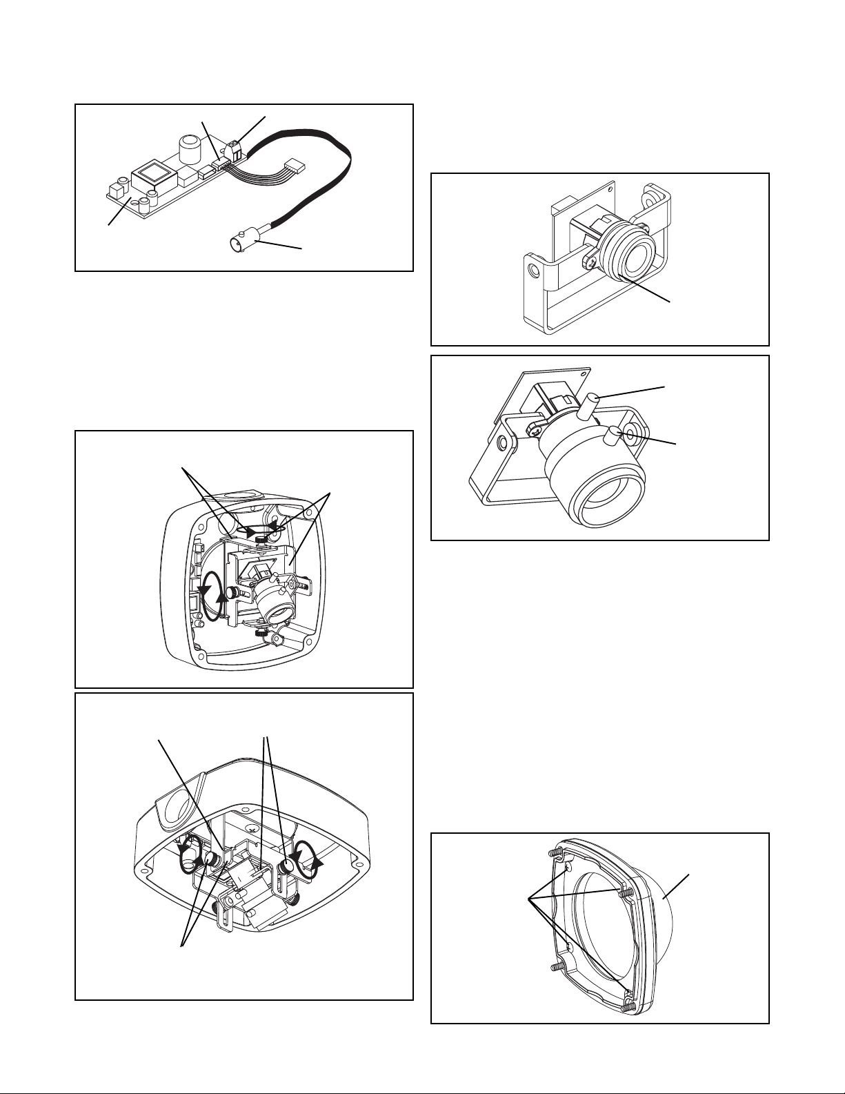
6. Connect the incoming 12 VDC or 24 VAC power to the
terminal strip on the PC board, located inside the housing.
Connect the wire harness on the PC board to the incoming
video (Figure 6).
Camera Connections
PC Board
Figure 6
7. Once you've made sure that the power and video are
operating, you can make final viewing adjustments to the
camera bracket.
Wall Mount: Use the camera cradle to pan the camera
right or left. Use the camera bracket to tilt
the camera up or down (Figure 7).
Ceiling Mount: If the ceiling is angled, use the camera
cradle to level the camera. Notches on the
rotating bracket will help you determine if
the cradle is level. Use the camera bracket
to tilt the camera up or down (Figure 8).
Terminal Strip
Video Cable
8. Fine focusing (see diagrams below):
Fixed Lens: Manually rotate the lens until a clear picture is
achieved (Figure 10).
Vari-Focal Lens: First, adjust the Magnification Lock Screw
to the desired magnification (telephoto
to wide angle). Tighten the Lock Screw.
Next, adjust the Focus Lock Screw until a
clear picture is achieved. Tighten the
Lock Screw (Figure 11).
Maunual
Focus
Figure 10
Magnification
Lock Screw
Thumb screws control tilting
of the camera bracket
Figure 7
Notches help determine
the horizontal position of
the cradle in relation to
the housing
Thumb screws
control the panning
of the camera
cradle
Wall Mount
Thumb screws control tilting
of the camera bracket
Focus Lock
Screw
Figure 11
8. Replace the housing top, but do not fasten the security
screws. Be sure the camera lens is not touching the dome.
If it is, adjust the brackets accordingly.
9. When the desired focus and location are achieved, use a
needle-nose pliers to tighten the thumb screws on the
brackets in place. Loctite™ should also be used to secure
the screws.
10. Replace the housing top and tightly fasten the (4) security
screws with the security tool.
NOTE: As your unit is used, the dome may become
scratched or damaged. If this happens, the dome
itself can be rotated to move the scratch away from
the viewing area. Simply remove the housing top,
loosen the (4) 10-32 screws that hold the plate to the
housing, and rotate the dome by hand (Figure 12).
Do not remove the screws or the plate from the
housing top. Once you've rotated the dome,
retighten the screws and replace the housing top.
Thumb screws control the leveling of
the camera cradle
Figure 8
Dome
10-32 Screws (4)
Ceiling Mount
Figure 12
- 2 -
Page 3

1. Read Instructions - All the safety and operating instructions
!
should be read before the unit is operated.
2. Retain Instructions - The safety and operating instructions
should be retained for future reference.
3. Heed Warnings - All warnings on the unit and in the operating
instructions should be adhered to.
4. Follow Instructions - All operating and user instructions should
be followed.
5. Electrical Connections - Only a qualified electrician should
make electrical connections.
6. Attachments - Do not use attachments not recommended by the
product manufacturer as they may cause hazards.
7. Cable Runs - All cable runs must be within permissible distance.
8. Mounting - This unit must be properly and securely mounted to
a supporting structure capable of sustaining the weight of the
unit. Accordingly:
a. The installation should be made by a qualified service
person, and should conform to all local codes.
b. Care should be exercised to select suitable hardware to
install the unit, taking into account both the composition of the
mounting surface and the weight of the unit. Be sure to
periodically examine the unit and the supporting structure to
make sure that the integrity of the installation is intact. Failure
to comply with the foregoing could result in the unit separating
from the support structure and falling, with resultant damages
or injury to anyone or anything struck by the falling unit.
SAFETY PRECAUTIONSIMPORTANT SAFEGUARDS
CAUTION
RISK OF
ELECTRIC SHOCK!
CAUTION: TO REDUCE THE RISK OF
ELECTRICAL SHOCK, DO NOT EXPOSE
COMPONENTS TO WATER OR MOISTURE.
The lightning flash with an arrowhead symbol,
within an equilateral triangle, is intended to
alert the user to the presence of non-insulated
"dangerous voltage" within the product's
enclosure that may be of sufficient magnitude
to constitute a risk of electric shock to persons.
The exclamation point within an equilateral
triangle is intended to alert the user to
!
UNPACKING
Unpack carefully. Electronic components can be
damaged if improperly handled or dropped. If an item
appears to have been damaged in shipment, replace it
properly in its carton and notify the shipper.
presence of important operating and
maintenance (servicing) instructions in the
literature accompanying the appliance.
Be sure to save:
1. The shipping carton and packaging material. They are the
safest material in which to make future shipments of the
equipment.
2. These Installation and Operating Instructions.
SERVICE
For service on Panasonic/Videolarm equipment contact:
Panasonic Technical Center
54 West Gude Dr.
Rockville MD 20850-1150
Phone: 301-762-5125
Fax: 301-251-0347
PANASONIC TECHNICAL SUPPORT
1-800-528-6747
9:00 AM - 5:00 PM EASTERN TIME
- 3 -
 Loading...