

Page 1
Manufactured by:
81-IN3041.9922
Before attempting to connect or operate this product, please read these instructions completely.
for
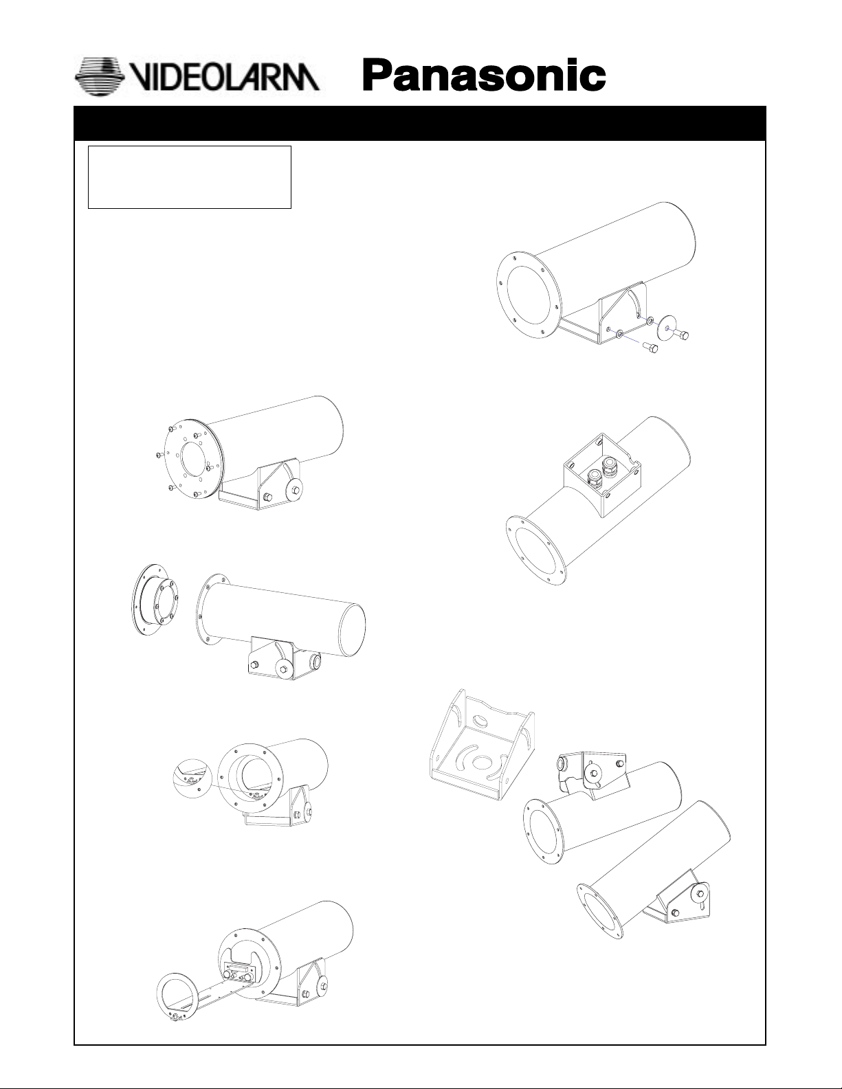
MODEL: Outdoor Camera Housing
PBRH10
STANDARD INSTALLATION PROCEDURE
NOTE: Maximum storage space is 10"
(Panasonic 1/3" camera class with Panasonic Vari-Focal lens
series)
1. Carefully remove the housing from its box.
2. Prepare installation site and gather needed tools and equipment.
3. Remove the (6) tamper resistance screws on the front of the
housing with the security tool provided in the installation packet.
Fig 1
Figure 1
PRODUCT INSTRUCTIONS
7. The next step is to remove the tilt bracket from the housing, this
is done by removing the (4) hex head bolts that hold the mounting
base to the housing. Fig 5
Figure 5
8. The cable strain reliefs that are provide in the kit can now be
screwed into the bottom of the housing. Fig 6
Figure 6
4. After the tamper resistance screws are out, the front end cap can
be removed from the housing. Fig 2
Figure 2
5. With the front endcap off to the side. You can remove the camera
sled from the housing by, loosen the camera adjustment screw.
Fig 3
Camera
Adjustment
Screw
6. The camera sled should now slide right out of the housing. Fig 4
Figure 3
9. The mounting bracket can be attached to the housing’s mounting
surface. Fig 7 With appropriate hardware. The housing can be
mount right side up or upside down. Fig 8 See wall mount
instructions when using PBWM10 (optional).
Figure 7
Figure 8
Figure 4
Page 2
10. With the mounting bracket attach to the mounting surface. All of the
incoming wiring can now be run through the tilt bracket. There is a
3/4" pipe treaded coupling on the backside of the tilt bracket. All
wiring should be run through that hole. The wiring can also be run
through the bottom of the tilt bracket, in which case you should plug
the 3/4" pipe coupling with a 3/4" pipe plug (plumbing or hardware
stores.)
11. The housing can now be reattached to the tilt bracket. Run the
incoming power wires through one of the strain relief’s and the video
cable through the other strain relief. The housing can be mounted
two ways to the tilt bracket, right side up or upside down. Fig 8
Reattach the housing to the tilt bracket with the (4) hex head bolts.
The (2) bolts with the large washers should be installed on the side
with the angled slot. Tilt the housing to the desired angle and tighten
all (4) of the tilt bracket hex head bolts.
Figure 8
14. With all of the wiring completed, slide the camera sled back into the
housing so that all of the wires go over the back wall of the camera
sled and circle back around and go out of the housing through the
strain reliefs. Fig 10
Figure 10
15. The front ring of the camera sled should sit approximately 2" inside
the housing Fig 11. The camera sled can be rotated to any angle and
secure in place, which allows you to mount the housing at any angle.
With the camera sled rotated to the desired angle. The camera sled
adjustment screws can now be tighten to secure the camera sled.
2.002.00
12. Attach your camera to the camera sled with the provided 1/4-20
screw. Fig 9 Adjust the camera so that the front of the lens is even
with the front tab of the camera sled.
Figure 9
13. Connect the incoming power wires to the housing pc board Fig. Pcb
Then connect the video cable directly to the camera and then run a
set of power wires from the housing pc board to the camera.
Input power for heater
Output to heater
ACH13_220PCB
A HTR 240 AC_I 240 AC_O BLR
THERM_H
VIDEOLARM INC. AMS 10/96
WARNING: Output power from the PC board will be the same as
Camera power, if the
same voltage as heater
THERM_B
incoming power. If camera power is differrent than accessory
power, DO NOT connect camera to PC board.
Figure 11
16. Reattach the front end plate with the (6) tamper resistant screws and
the provided security tool. Make sure that the window and window
plate does not touch the camera sled bracket.
INSTRUCTIONS FOR MOUNTING OPTIONAL PBWM10 BRACKET
1. Start the installation by removing the access cover, this is done by
loosening the (2) security screws at the front of the housing with the
provide security tool. Set the access cover and screws aside. Fig 12
- 2 -
Page 3
PBWM10
Figure 12
2. Mount the wall bracket to the wall with appropriate hardware. Fig 13
shows the mounting pattern of the mounting surface.
2.000
.500
1.500
Figure 13
2.000
5.500
.500
1.000
4X .390Ø
3. Run all incoming wiring through the hole in the back plate of the wall
mount bracket and up through the hole in the housing mounting
surface (in between the (4) threaded inserts). Fig. 14
Figure 14
4. Installation of the PBRH10 Tilt bracket (See steps 1-8 in the PBRH10
Installation instructions): Using the (2) 3/8" hex head bolts and
washers that are provided with the wall mount secure the tilt bracket
to the wall mount. Fig. 14 The wall mount has (4) threaded inserts
in which the (2) 3/8" hex head bolts attach. By alternating the pattern
of the (2) bolts you can achieve any pan angle you wish. Fig. 15, 16.
Figure 16
Figure 15
5. After achieving the desired pan angle tighten down the (2) 3/8" hex
head bolts. Continue the installation of the housing (steps 11-16 in
the PBRH10 Installation instructions).
6. The wall mount packet assembly includes a 3/4" pipe plug, which is
to be treaded into the pipe coupling at the back of the tilt bracket.
7. After the housing is installed the wall mount access cover can be
reinstalled. Fig. 17, 18
Figure 17
Figure 18
987654321
19181716151413121110
Part Number Description Qty.
1 90-BTSEC06 10-32X 5/8" BT HD SEC SCREW SS 6
2 92-WSTH04 #10 EXT TOOTH STAR L/W SS 14
3 30-VL1437 FRONT END PLATE, PBRH10 1
4 96-GKBMT01 PBRH10, FRONT END PLATE GASKET 1
5 96-GKBMT02 PBRH10, WINDOW GASKET 1
7 27-WDBMT10 BALLISTIC WINDOW FOR PBRH10 1
8 30-VL1439 WINDOW PLATE, PBRH10 1
9 90-BTRP32 10-32 X 1 3/8" PN HD PHIL SS 6
10 90-BTRP20 #10-32 X 3/8" PN HD PHIL SS 2
11 90-BTSC01 10-32 X 1/2 SOCKET CAP SCREW 1
12 30-VL1442 FRONT CAMERA PLATE, PBRH10 1
13 30-VL1436 CAMERA SLED FOR PBRH10 1
14 90-BTHH04 1/4-20X1/2 RD HD SS 1
15 92-WSSL01 1/4 SPLIT LOCKWASHER 18-8 SS 1
16 90-BTSR17 #6-32 X 3/8" PN HD PHIL SS MS 1
17 72-HTP115 115VAC, 28 WATT HEATER 1
18 50-VL1435 PBRH10 HOUSING BODY, SS 1
19 30-VL1494 PBRH10 TILT BRACKET 1
20 94-FSSR02 BLK HEYCO STRAIN RELIEF #3224 2
21 92-WSSL02 5/16 SPLIT LOCKWASHER SS 4
22 90-BTHH33 5/16-18 X 3/4 HH SS 4
23 92-WSFN04 5/16" FLAT WASHER FOR BMT10 2
24 PBWM10 WALL MOUNT BRACKET (OPTIONAL) 1
23
22
21
20
- 3 -
Page 4

1. Read Instructions - All the safety and operating instructions
!
should be read before the unit is operated.
2. Retain instructions - The safety and operating instructions
should be retained for future reference.
3. Heed Warnings - All warnings on the unit and in the operating
instructions should be adhered to.
4. Follow Instructions - All operating and user instructions should
be followed.
5. Electrical Connections - Only a qualified electrician should
make electrical connections.
6. Attachments - Do not use attachments not recommended by the
product manufacturer as they may cause hazards.
7. Cable Runs - All cable runs must be within permissible distance.
8. Mounting - This unit must be properly and securely mounted to
a supporting structure capable of sustaining the weight of t he
unit. Accordingly,
a. The installation should be made by a qualified service person
and should conform to all local codes
b. Care should be exercised to select suitable hardware to install
the unit, taking into account both the composition of the mounting
surface and the weight of the unit. Be sure to periodically
examine the unit and the supporting structure to make sure that
the integrity of the installation is intact. Failure to comply with the
foregoing could result in the unit separating from the support
structure and falling, with resultant damages or injury to anyone
or anything struck by the falling unit.
SAFETY PRECAUTIONSIMPORTANT SAFEGUARDS
CAUTION
RISK OF
ELECTRIC SHOCK!
CAUTION: TO REDUCE THE RISK OF
ELECTRICAL SHOCK, DO NOT EXPOSE
COMPONENTS TO WATER OR MOISTURE.
The lightning flash with an arrowhead symbol,
within an equilateral triangle, is intended to alert
the user to the presence of non-insulated "
dangerous voltage" within the product's enclosure
that may be of sufficient magnitude to constitute
a risk of electric shock to persons.
The exclamation point within an equilateral triangle
is intended to alert the user to presence of
!
UNPACKING
Unpack carefully. Electronic components can be damaged if
improperly handled or dropped. If an item appears to have been
damaged in shipment, replace it properly in its carton and notify
the shipper.
important operating and maintenance (servicing)
instructions in the literature accompanying the
appliance.
Be sure to save:
1. The shipping carton and packaging material. They are the safest
material in which to make future shipments of the equipment.
2. These Installation and Operating Instructions.
SERVICE
For service on Panasonic/Videolarm equipment contact:
Panasonic Technical Center
54 West Gude Dr.
Rockville MD 20850-1150
Phone: 301-762-5125
Fax: 301-251-0347
PANASONIC TECHNICAL SUPPORT
1-800-528-6747
9:00 AM - 5:00 PM EASTERN TIME
- 4 -
 Loading...