

Panasonic NVSD200BA User Manual

Video Cassette Recorder
NV-SD200BA
NV-SD190BA
VQT6280
VUS MiVM A!
* iNmUGn^T CONTROL SYSTSM
Before attempting to connect, operate or adjust this product,
please read these instructions completely.
Dear Customer
May we take this opportunity to thank you for purchasing this
Panasonic Video Cassette Recorder.
We would particularly advise that you carefully study the
Operating instructions before attempting to operate the unit and
that you note the listed precautions.
IMPORTANT
Your attention is drawn to the fact that
recording of pre-recorded tapes or discs
or other published or broadcast materiai
may infringe copyright laws.
Contents
Connections
Tuning the TV to your VTR
Setting the Clock of the VTR................................ 5
Storing TV Broadcasts into your VTR
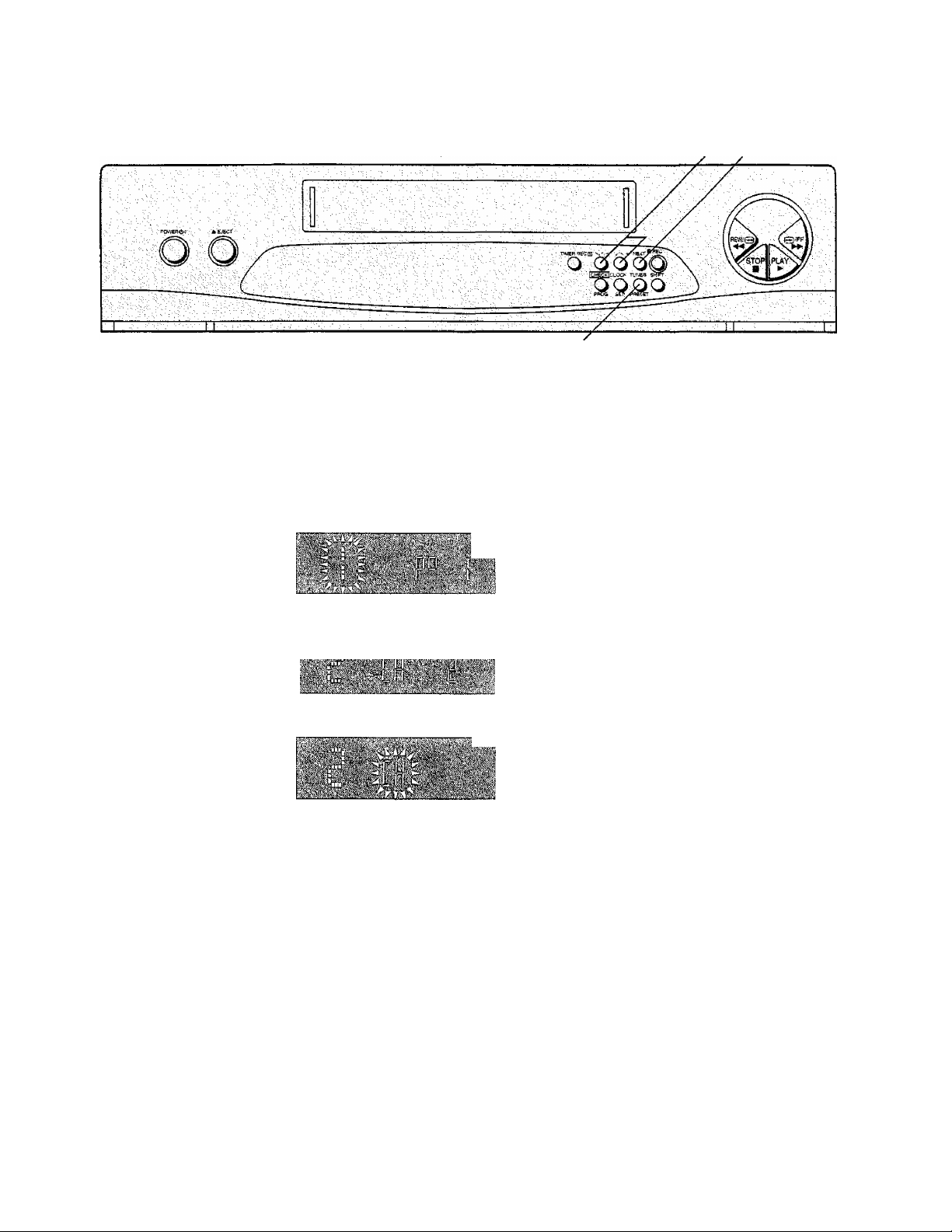
Controls and Connection Sockets
..........................................................
..................................
................
.....................
3
4
6
8
WARNING
TO REDUCE THE RISK OF FIRE OR
SHOCK HAZARD, DO NOT EXPOSE
THIS EQUIPMENT TO RAIN OR
MOISTURE.
FOR YOUR SAFETY
B DO NOT REMOVE OUTER COVER.
To prevent electric shock, do not remove
cover. No user serviceable parts inside. Refer
servicing to qualified service personnel.
m AC MAINS LEAD CONNECTION
The wires in the mains lead of this apparatus
are coloured in accordance with the following
code.
Important
b=i-BLUE
Mains Lead
As the colours of the wires in the mains lead may
not correspond with the coloured markings
identifying the terminals in your plug proceed as
follows: The wire which is coloured BLUE must be
connected to the terminal which is marked with the
letter N or coloured BLACK. The wire which is
coloured BROWN must be connected to the
terminal which is marked with the letter L or
coloured RED.
Under no circumstances must either of the above
wires be connected to the earth terminal of a three
pin plug.
................
BROWN ....
.... NEUTRAL
...............
LIVE
...............
1' .
Playback
On-the-spot Recording
•Assembly Editing
■
..............1 ..........................
Timer Recording
Other Functions
............................
_
..................
.. ... .
..............
...............
.. ^
.......
, ■ ■
i 1 ■: ..I
..
:
■
.
Before Requesting Service....................................... 17
Precautions............................................................. 19
Specifications.................................................................................. 20
10
12
13
14
16
HQ (High Quality) Picture System
Video recorders carrying the HQ symbol mark feature the
new VHS High Quality Picture System. This system
assures complete compatibility with VTRs that use the
conventional VHS system.
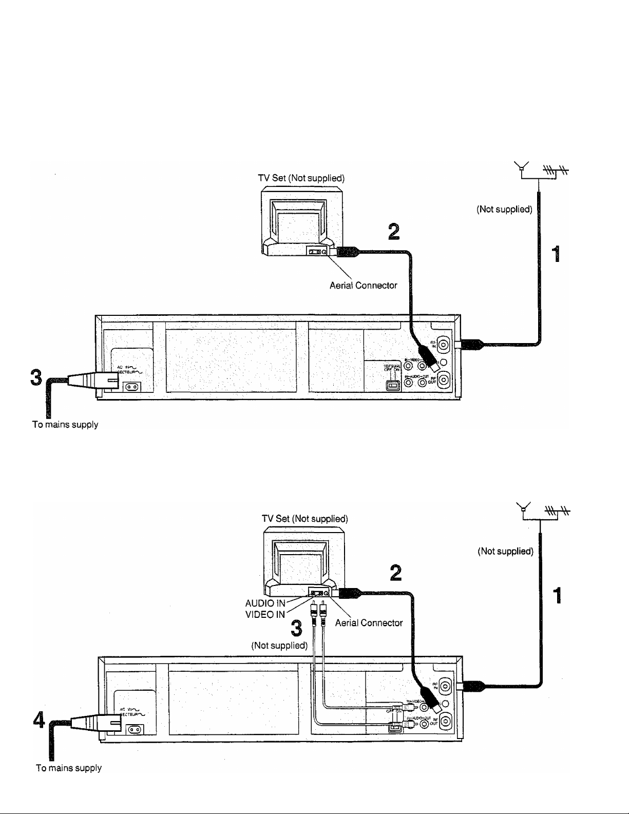
Connections Connections
This tells you how to connect the VTR to an aerial, TV, etc.
Basic Connections
The following connections are required to record and piay
back the VTR through a TV set:
Aerial
Connection to a TV Set with the Audio/Video Input Sockets
Aerial
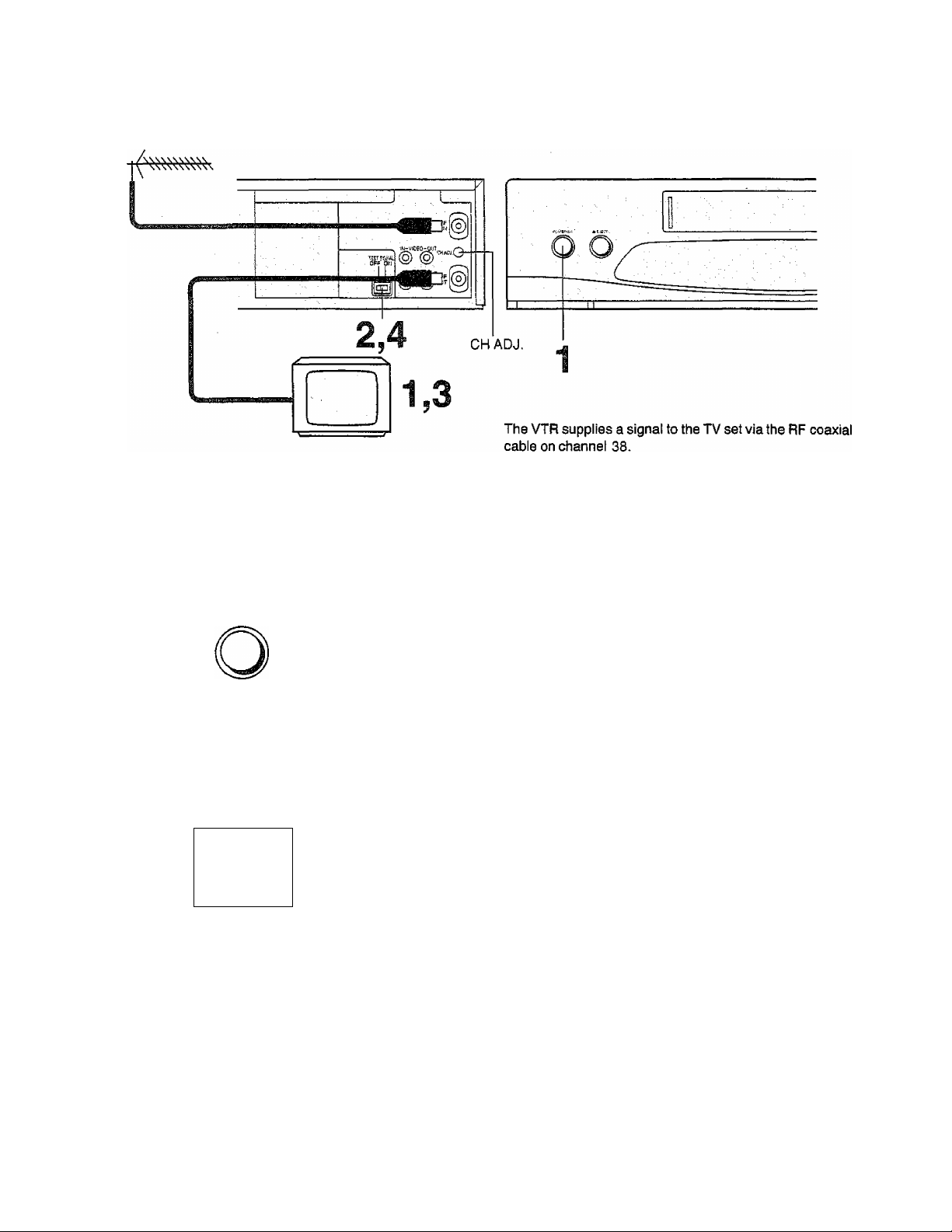
Tuning the TV to your VTR
it is possible to view the video picture on your TV in the
same way that you watch TV broadcasts.
It you have connected the VTR to the TV through the video
and audio input sockets then you do not need to foliow the
procedure mentioned below.
Operations
1
^
...............
POWER 6^t
TEST SIGNAL
OFF ON
cn
TEST SIGNAL
OFF ON
□=i
Turn on the TV and VTR.
To generate a test pattern, set TEST
SIGNAL to ON.
Set the TV to an unused position which you
.
wish to use for your video playback.
Set TEST SIGNAL to OFF.
Note:
The test signal is transmitted on video channel 38.
If you are encountering interference from a TV broadcast on
this video channel, you may readjust to another free
channel (30-40) by using the CH ADJ, screw which is
located on the rear of the VTR.
Please note that if the CH ADJ. screw is used then you will
have to retune your TV to the test signal as in item 2 to 4
above.
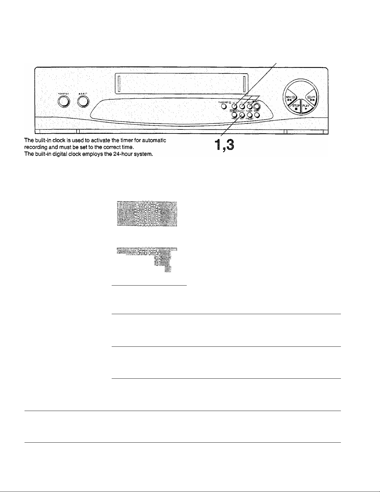
Setting the Clock of the VTR
Tuning the TV to your VTR
Setting the dock of the VTR
Preparation
Turn on the VTR,
Operations
CLOCK
Display Symbols
1
9
2 Set each item by pressing + or — and NEXT.
i
- ^+
oo
For Example:
Date; 16th, October, 1999
Time; 20:15
Keep CLOCK SET pressed for more than 2 seconds.
Set Year “99”.
Set Month “10".
Set Date “16”.
NEXT
—
o
3 o
SET
Time Reset Function
If the clock is less than two minutes slow or fast, it can
easily be reset to the proper time.
For example:
Resetting the clock to 12:00.00
Set Hour “20”.
Set Minute “15”.
•There is no need to press NEXT.
Press CLOCK SET.
•The clock will start.
1 Keep CLOCK SET pressed at any time between
11:58.00 and 12:01.59 for more than 2 seconds.
2 Press CLOCK SET again as soon as you hear the
12:00.00 time signal.
storing TV Broadcasts into your VTR
2,3 2
1,4
Introduction
The VTR is fitted with its own tuner (just like a normal TV
set) and can be pre-set to receive up to 42 TV broadcast
stations.
Preparation
•Confirm that the TV is on and the VTR viewing channel is
selected.
•Turn on the VTR and select the programme position
except AV,
Operations
1
oo
X/ - xx +
oo
TUNER
o
PRESET
- /X +
TUNER
o
PRESET
Dispiay Symbols
Keep TUNER PRESET pressed for more than 2 seconds.
r—Select the programme position, then press
NEXT
mcvt
/ I NEXT.
Search for the required TV station.
Press TUNER PRESET twice.
r a r i-

Fine Tuning Procedure
1 Keep TUNER PRESET pressed for more than
2 seconds, and then press again.
2 Press NEXT.
3 Press + or - to obtain the best tuning condition.
®“A" Indicator disappears.
®To return the tuning to its former state, press SHIFT.
4 Press TUNER PRESET.
Storing TV Broadcasts into your VTR
Blanking of Unoccupied Programme Positions
1 Keep TUNER PRESET pressed for more than
2 seconds.
2 Select a programme position which you do not want to
tune to a TV station, by using + or -.
3 Press SHIFT. (“- is displayed.)
• Repeat steps 2 and 3 for other unoccupied programme
positions to skip during the selection of the programme
positions.
•To cancel the blanking of a programme position, select
that programme position on the VTR and then press
SHIFT.
4 Press TUNER PRESET twice.
Channei Pian
VHF
4-13
UHF
21-68
 Loading...