

Panasonic NV-HS950AM User Manual
Operating Instructions
Video Cassette Recorder
NV-HS950AM
li
li-
* i I
I I ■*
■?: #i
• ¿S :. ^ <y f- ■■ i ■
-, : . ■ ■, .lUUm ■ ■
:::
¡ " I ■
f iil » Í '
Í I “
:t J ; .
i * Í il
-, .. * Ì
■ - .1
% ^ ^ ■ m
: .* :■ ■ 1 ‘
fl
it
i|
: ,. Í ^ * i- ■- - - # Í
'4
.... i :
f t
.. » *■ i '
. * . s *
. . : , » ■■ - 1 . ■
■immmmmmmm * ■-
" 1 ^ ¿ y y \ ^ if ^ Í :4
. •<•: 4> i- 4: M ¥ f
^ ^ ^ ^ ^ ^ ^ ■
. Í ^
. H . . t r 1 M Í Í ♦ ■
*-
. .. .è Ji # -f-
Í . ; y - # ^ - f t
^ yy ■ f- f t •#: ^
^ ^ M "W- ■$' ^ "
■ f f- J ¿ Í i Í-
- Í.» (i Í t # f -
I- è *#♦♦■# # -*■
■■■ f- t É i # ? 4 ■*
j -s f- -f * t ■» • i
. -Í i- 4 i -Í I Í
. - I* #■ -t i 11 ■#
■■ # f f i- f .*
,i ^ i é *
SUPER miVE
625
Before attempWr>g to connect, operate els' adju^ ti^
^ product, please read these iristrudtions completely.
MULTt-lfiréUlGENt CÓNfioi
Dear Customer
May we take this opportunity to thank you for purchasing
this Panasonic Video Cassette Recorder.
We would particuiariy advise that you carefuliy study the
Operating instructions before attempting to operate the
unit and that you note the listed precautions.
Auto Tuning
G-Code Programming System
Programming is now easier than ever: simply enter the
G-Code number provided in the programme schedule
column carried by newspapers and magazines.
•G-code is a trademark of Gemstar Development
Corporation. The G-code system is manufactured under
license from Gemstar Development Corporation.
Crystal View Control
CVC circuit for automatic tape calibration and optimizing
of playback characteristics.
During playback the contrast of tapes recorded with good
level is automatically optimized.
On Screen Display
Auto-setup in progress,
Auto Tuning is completed.
All broadcasting stations that can be received in the area
are automatically tuned and sotred in memory.
•Dont’t turn off the VCR halfway.

IMPORTANT
Your attention is drawn to the fact that
recording of pre-recorded tapes or
discs or other published or broadcast
material may infringe copyright laws.
Contents
Description
Controls and Connection Sockets
Infra-red Remote Controller ............................................. 8
...................................
4
WARNING
TO REDUCE THE RISK OF FIRE OR
SHOCK HAZARD, DO NOT EXPOSE
THIS EQUIPMENT TO RAIN OR
MOISTURE.
Remarks
1. This VCR is capable of receiving
SECAM type broadcasting
programmes (SECAM B/G) and
recording/playing back its colour
television signals.
2.
When a cassette which has been
recorded on this VCR is played back on
a SECAM VCR, the picture may be
reproduced in black and white. When it
is played back on a PAL VCR without
SECAM capability, the picture may be
not reproduced in normal colour.
When cassettes recorded on a SECAM
3.
VCR or SECAM pre-recorded cassettes
are played back on this VCR, the picture
is reproduced in black and white.
4.
This VCR is not designed for use in
France, where a SECAM VCR should
be used instead.
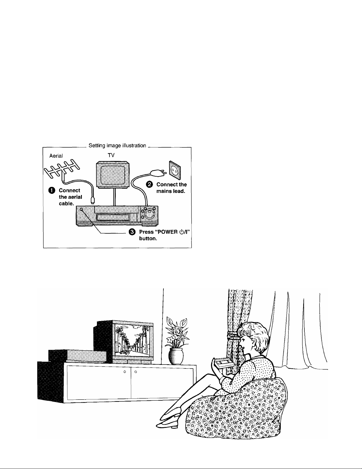
Setting Up
Connections ...................................................................... 12
Tuning the TV to your VCR .............................................. 16
Auto Setup
........................................................................
17
Various Settings
Storing TV Broadcasts into your VCR.......................... 18
Setting the Clock of your VCR
Settings Using On Screen Display
Setting the Remote Controller
for Operation of your TV
.....................................
...............................
...........................................
21
22
25
Basic Operations
Playback
Manual Recording ........................................................... 29
•One-Touch Recording (OTR)
..........................................................................
.........................................
27
31
As this equipment gets hot during use,
operate it in well ventilated place; do not
install this equipment in a confined space
such as a book case or similar unit.
FOR YOUR SAFETY
■ DO NOT REMOVE OUTER COVER.
To prevent electric shock, do not remove
cover. No user serviceable parts inside. Refer
servicing to qualified service personnel.
Advanced Operations
Timer Recording
•G-Code Programming
• Using the Remote Controller........................................... 33
• Using On Screen Display
Other Functions
Editing............................................................................... 38
•Assembly Editing.............................................................. 38
• Audio Dubbing................................................................. 39
• Insert Editing .................................................................. 41
•One-Touch-Editing
..............................................................
.....................................................
................................................
..............................................................
...........................................................
32
32
34
36
42
Helpful Hints
Before Requesting Service
Precautions
Specifications................................................................... 47
......................................................................
.............................................
43
46
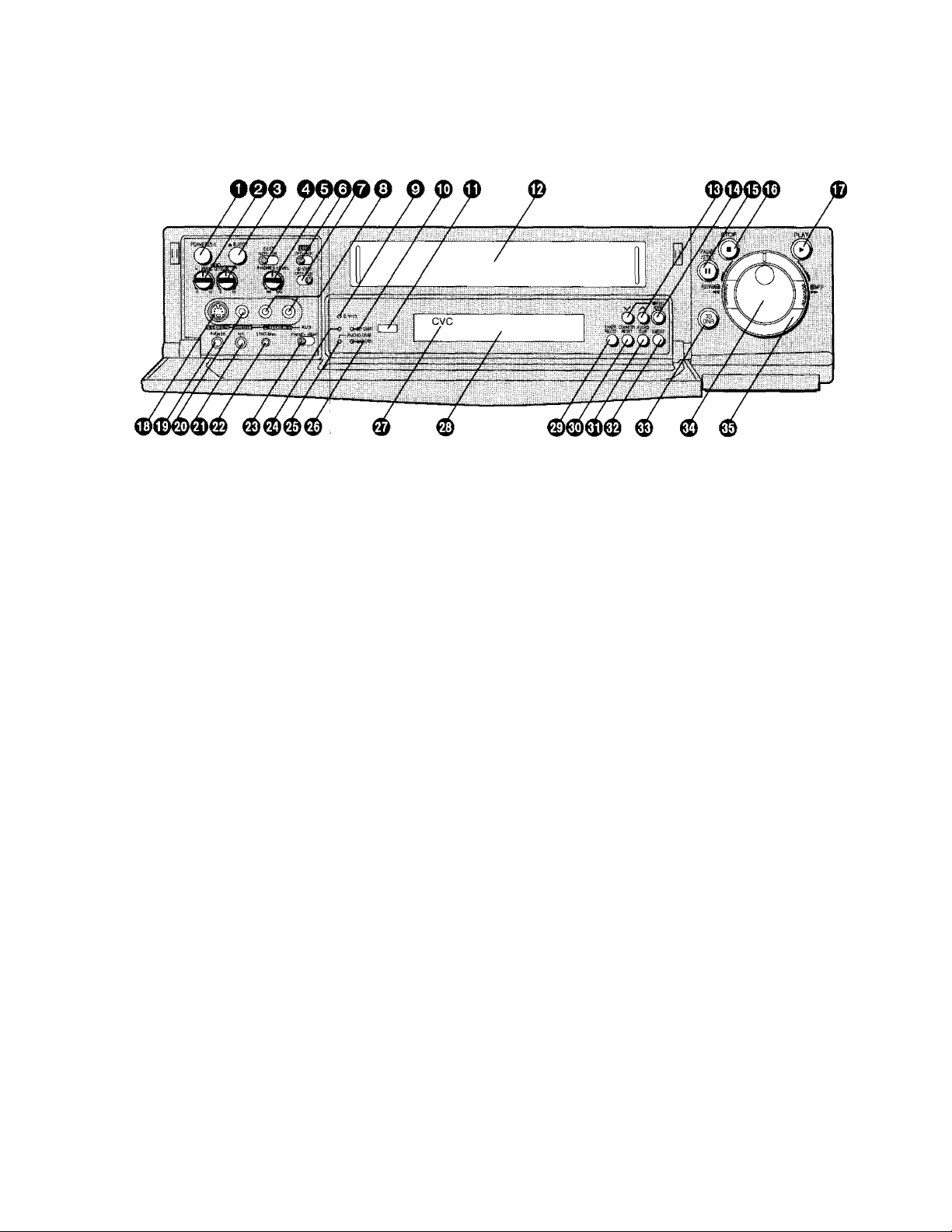
Controls and Connection Sockets
This gives a detailed explanation of th^ function of each button, switch and connection socket.
POWER 6/1 (VCR 6)
Press to switch the VCR from on to standby mode or
vice versa. In standby mode, the VCR is still
connected to the mains.
AUDIO REC LEVEL
e
To adjust the recording level to p4ak at +4 dB on the
recording level indicator. |
EJECT
o
To eject a video cassette.
EDIT
o
OFF:
ON:
0
© TBC
For normal use of the VCR.
Select this position when editing.
The picture quality is set to a status which is
suited to editing. ■
•The 3D DNR function ceases to work.
•The TBC does not function during slow
playback or still-picture playback.
•This must be set to ON vyhen performing
editing operations using jhe VITC code.
PHONES LEVEL
For adjusting the volume level of connected stereo
headphones.
When the tape in the cassette is loose or damaged,
or when the tape movement is un$table during
recording or playback, the playback picture may
shake from side to side and the picture may become
distorted. In this case, activate th^ Time Base
Corrector by setting the TBC Switdh to ON, and the
picture will become stable and thq shaking will be
minimized.
• For normal use, set the TBC Swjtch to OFF.
• During playback, the picture may shake vertically or
horizontally. In such a case, set the TBC Switch to
OFF.
•This function wilt not work during NTSC playback.
O s-vHs
When recording on an S-VHS cassette tape, select
the desired recording format with this switch.
ON: The recording will be made in the S-VHS
format.
•The S-VHS indicator lights up.
OFF: The recording will be made in the VHS format.
•The S-VHS indicator does not light up.
(It is possible to make a recording on an
S-VHS cassette tape in the VHS format, for
example, in order to play back the tape on
another VHS VCR.)
•When using VHS cassettes, the recording is made
in the VHS format irrespective of the position to
which this switch is set.
•When a tape which was recorded in the S-VHS
format is played back on a conventional VHS VCR,
it is not possible to obtain playback picture.
© AUDIO IN (AV3)
To connect the audio cable to a movie camera or to
another VCR.
© S-VHS Indicator
Lights up when the S-VHS format.
© 3D DNR Indicator
When the 3D DNR function is on, this indicator is lit.
0 Infra-red Remote Control Receiver Window
© Cassette Compartment
Insert a video cassette here.

To select the required programme position (TV
station).
These buttons can also be used for tracking
adjustment and vertical locking adjustment.
See page 9.
(D REC/OTR
To start a recording.
For One-Touch Recording (OTR).
0 II (PAUSE/STILL)
In the stop mode: Still picture (Jog/Shuttle mode).
During playback:
•By pressing: Still picture. “QD” is lit.
(Jog/Shuttle mode).
During recording: Interrupts recording.
■ (STOP)
<D
To stop any playback or recording.
► (PLAY)
To start playback. “[>” is lit.
For the repeat playback function.
S-VIDEO IN (AV3)
0
To connect the S-Video cable to a movie camera or
to another VCR that has a S-Video output socket.
• If the S-Video cable is connected, other video input
(AV3) is automatically switched off.
PHONES
0
To connect stereo headphones.
0
VIDEO IN (AV3)
To connect the video cable to a movie camera or to
another VCR.
0 MIC
To connect the microphone for recording. Once
connected, this socket has priority.
© SYNC/8mm
To connect the synchro connection cord {VW-K10E/
VW-K1E) to a movie camera or another VCR
equipped with synchronized editing capability.
To connect a movie camera or another VCR
equipped with LANC socket for One-Touch-Editing.
0 AV3 Selector
When Recording via the AV3 sockets on the front
panel or rear panel, set this switch to FRONT or
REAR.
0 Standby Indicator
This indicator is lit when the VCR is turned off or the
VCR is timer recording standby mode.
0 AUDIO DUB Indicator
This indicator is lit when the audio dubbing is
performed.
0 INSERT Indicator
This indicator is lit when the insert editing is
performed.
0 CVC Indicator
This indicator is lit when the power is ON.
0 Display 0 TIMER REC
To turn the timer recording function on and off.
ID is lit or not lit.
Once operating timer recording function, the normal
VCR operation is not possible unless this button is set
to off.
© COUNTER RESET
To reset the tape counter (elapsed time) to “0:00.00”.
•The tape counter is automatically reset to “0:00.00"
when a video cassette is inserted.
0 AUDIO DUB
To set up the VCR for audio dubbing.
0 INSERT
To set up the VCR for insert editing.
0 3DDNR
ON: Using the 3D DNR function, playback is
performed in the state which achieves
optimum picture quality in light of
characteristics of a tape.
•The 3D DNR indicator is lit.
•This control should normally be left in the
ON position.
•The 3D DNR function does not work during
NTSC playback.
OFF: Turn off the 3D DNR function.
•The 3D DNR indicator is not lit.
0 Jog Dial
To locate any desired frame with utmost precision.
0 Shuttle Ring
In the stop mode: To rewind or fast forward the tape.
In the playback mode:
To search picture backward or
forward.
In the still playback mode:
To adjust playback speed
backward or forward.
In the rewind or fast fonward mode:
To obtain high speed picture.
c
o
O
O)
CD
Q
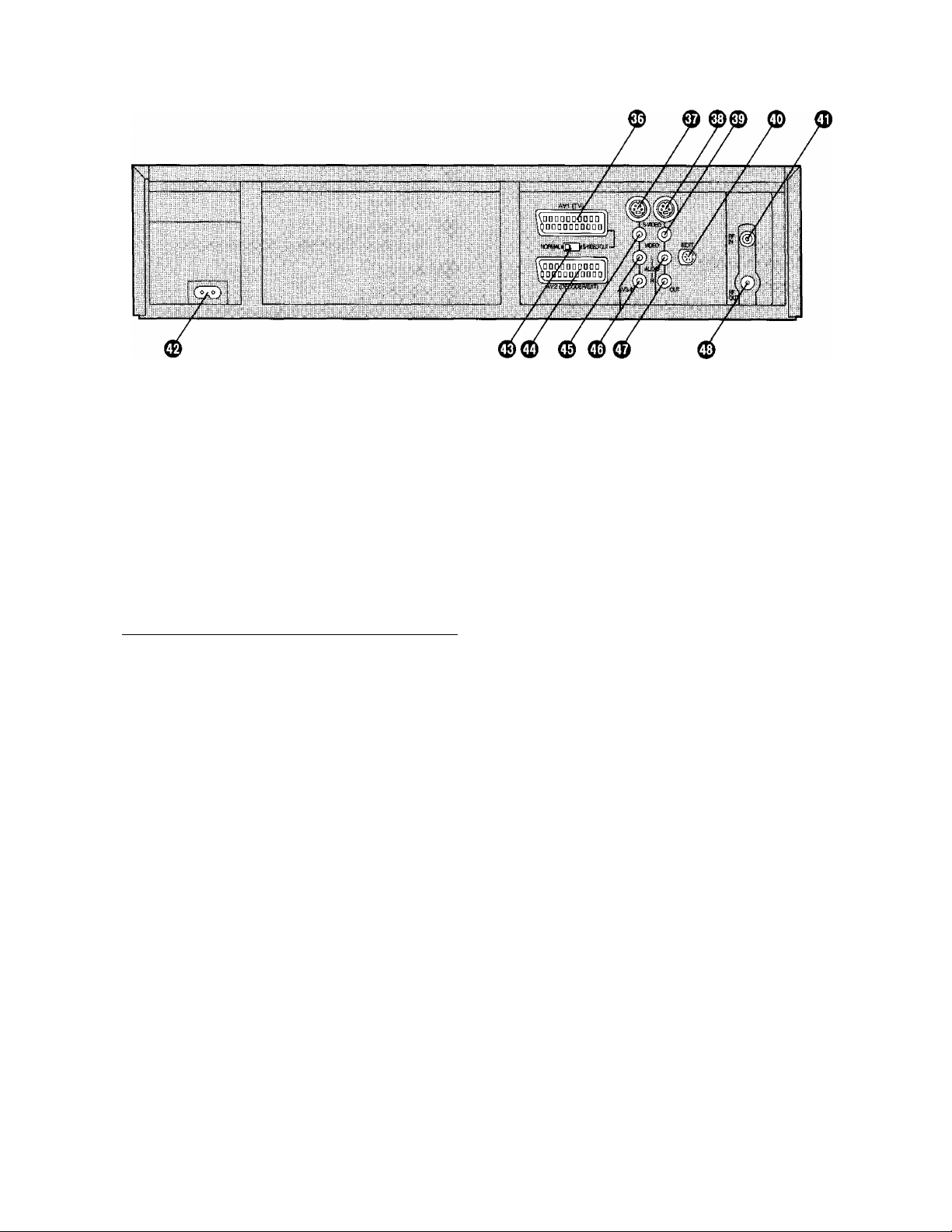
© AVI (TV)
This 21-pin scart terminal carries input and output
signals for both picture and sound. TV sets equipped
with a similar socket can be connected here.
This is also called Scart
Peritel
Euro Connector
Euro AV
20 18 16 14 12 10 8 6 4 2
\9 17 15 13 11
NORMAL (AVI/AV2)
9 7 5 3 1
S-VIDEO (AVI)
1 AUDIO OUTPUT 1 AUDIO OUTPUT
CH2 (R) CH2 (R)
2 AUDIO INPUT 2 AUDIO INPUT
CH2 (R)
3 AUDIO OUTPUT
CHI (L)
CH2 (R)
3 AUDIO OUTPUT
CHI (L)
4 AUDIO GND 4 AUDIO GND
5 BLUE GND 5 No connection
6 AUDIO INPUT CHI (L)
7 BLUE
6 AUDIO INPUT CHI (L)
7 No connection
8 SWITCHING 8 SWITCHING
VOLTAGE VOLTAGE
9 GREEN GND
9 No connection
10 Control (AVI only) 10 Control
11 GREEN
12 No connection
11 No connection
12 No connection
13 RED GND 13 COUTGND
14 BLANKING GND
15 RED
16 BLANKING
17 VIDEO OUTPUT GND
18 VIDEO INPUT GND
19 VIDEO OUTPUT
20 VIDEO INPUT
21 GND
Caution: RGB reservation
14 No connection
15 COUT
16 No connection
17 YOUTGND
18 VIDEO INPUT GND
19 YOUT
20 VIDEO INPUT
21 GND
for only E/E operation
when connecting the Pay TV decoder
© S-VIDEOIN(AV3)
To connect the S-Video cable to a movie camera or
to another VCR that has a S-Video output socket.
• If an S-Video cable is connected, other video input
(AV3) is automatically switched off.
© S-VIDEO OUT
To connect the S-Video cable to a TV or another VCR
that has a S-Video input socket.
© VIDEO OUT
To connect the video cable to a TV or another VCR.
© EDIT
By connecting the optional Editing Controller
(VW-EC310EA/W-EC300E) to this socket, such
editing functions as Assemble Editing, Insert Editing
and Audio Dubbing can be performed more quickly
and efficiently between two VCRs or between a VCR
and a movie camera.
To connect the supplied Edit cable to a movie camera
or to another VCR for One-Touch-Editing.
© RFIN
To connect to the external aerial.
® AC IN
TO connect to the main power supply.
© NORMAL/S-VIDEOOUT
NORMAL: Normally set to this position.
S-VIDEO OUT (AVI):
Set to this position when connecting the
VCR to a TV set equipped with 21-pin
Euro-AV Connector with pins for separate
Y/C signal input.
© AV2 (DECODER/EXT)
To connect to a decoder, another VCR or a satellite
receiver.

© VIDEO IN (AV3)
To connect the video cable to a movie camera or to
another VCR.
0 AUDIO IN (AV3)
To connect the audio cable to a movie camera or to
another VCR.
0 AUDIO OUT
To connect the audio cable to a stereo audio system.
© RFOUT
To connect to the aerial terminal on a TV set.
C
.O
•4^
.Q.
C
o
CO
CD
Q
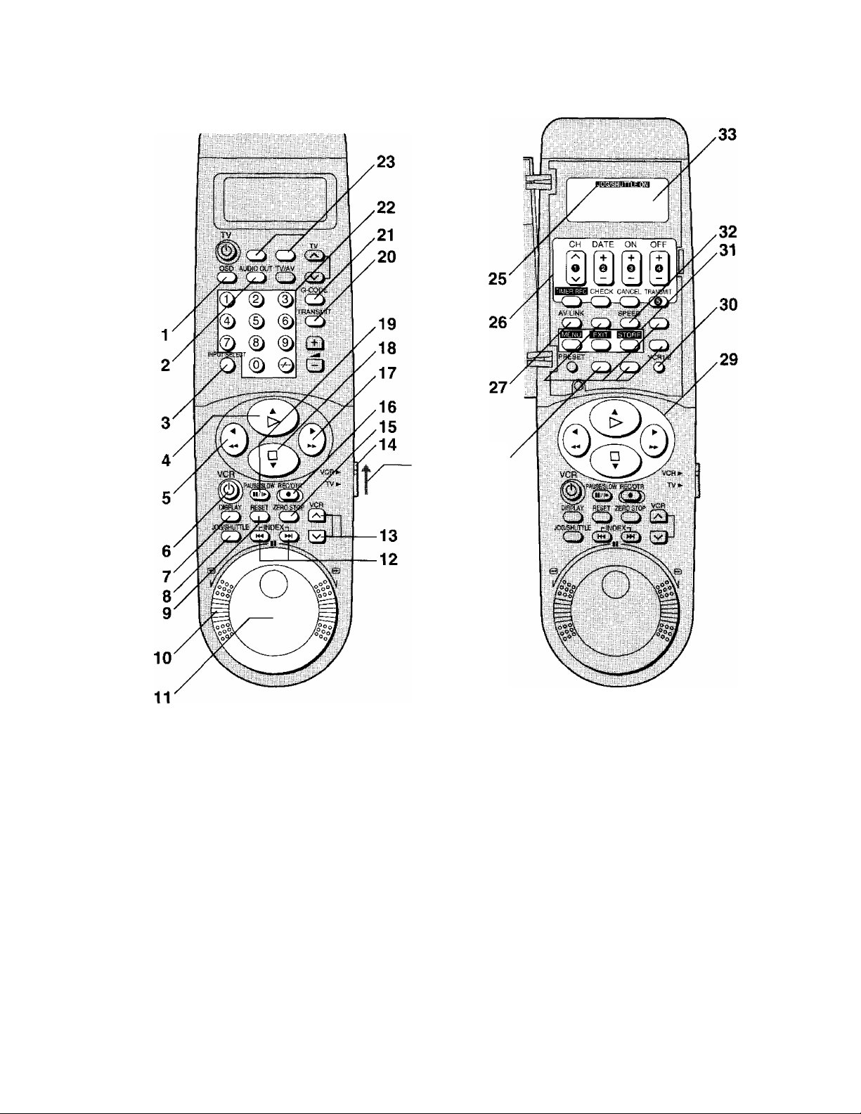
Infra-red Remote Controller
24
Set VCR/ 28
TV switch to
VCR for using
the numeric
buttons.
VCR OPERATION
1 OSD
For the On Screen Display function.
2 AUDIO OUT
To select the desired sound mode.
At the every push of this button, the audio output
mode changes as follows.
Stereo-^Left^Right-^Normal audio--------------—
track
The Left (L) and Right (R) Indicators shown which
sound mode is selected in the following way.
Stereo: Both the L and R Indicators appear.
Left: The L Indicator appears.
Right: The R Indicator appears.
Normal: Both the L and R Indicators don’t appear.
INPUT SELECT
To select the A1, A2 or A3 external recording source.
> (PLAY)
To start playback. “l>” is lit.
For the repeat playback function.
5 (REWIND)
In the stop mode;
In the playback mode:
In the rewind mode:
“OO” is lit.
6 VCR
Press to switch the unit from on to standby mode or
vice versa. In standby mode, the unit is still
connected to the mains.
DISPLAY
To change the indication on the VCR Display or On
Screen Display.
Clocks Counter-^ Remaining Tape Time-
To rewind the tape.
To search backward.
To obtain high speed picture.
C
8 JOG/SHUTTLE
Press this to switch to the Jog/Shuttle mode and
cause JOG/SHUTTLE ON to appear on the remote
controller display. Press again to make JOG/
SHUTTLE ON disappear.
In the stop mode: Still picture (Jog/Shuttle mode).
During playback: Still picture (Jog/Shuttle mode).

9 RESET
To reset the tape counter (elapsed time) to “0:00.00”.
•The tape counter is automatically reset to “0:00.00"
when a video cassette is inserted.
10 Shuttle Ring
Operate after pressing the JOG/SHUTTLE button to
switch to the Jog/Shuttle mode.
To adjust piayback speed backward or fonward.
11 Jog Dial
Operate after pressing the JOG/SHUTTLE button to
switch to the Jog/Shuttle mode.
To locate any desired frame with utmost precision.
12 INDEX
For the index search function.
13 V (VCR), TRACKING/V-LOCK +/-
To select the required programme position (TV
station).
For tracking adjustment and vertical locking
adjustment
• For manual tracking adjustment
The - and + buttons are used to adjust the tracking
when, for example, noise bars on the picture are
better removed manually than by automatic digital
tracking controi.
Press both buttons together to return to automatic
digital tracking control.
• For slow tracking adjustment
When noise bars appear during still or slow
playback, switch over to slow playback and adjust
with the - or + button to reduce the noise bars.
• For vertical locking adjustment
Use the - and + buttons to minimize any vertical
jitter during still picture playback.
Adjustment is not possible when the TBC is working.
14 VCR/TV switch
VCR: Seiects the VCR operation mode.
TV; Selects the TV operation mode.
15 ZERO STOP
For the zero stop function.
16 REC/OTR
To start a recording.
For One Touch Recording.
17 ►► (FAST FORWARD)
In the stop mode: To fast forward the tape.
In the playback mode: To search forward.
In the fast forward mode: To obtain high speed
picture.
“>t>” is lit.
18 □(STOP)
To stop any playback or recording.
19 PAUSE/SLOW(ll/l»^)
During playback:
• By pressing: Still picture. “QD” is lit.
• By pressing for 2 seconds or more:
Slow piayback. “Dt>” is lit.
During recording: Interrupts recording.
20 TRANSMIT
To transmit the data that has been set on the remote
controiler to the VCR.
21 G-CODE
For the G-Code programming.
22 Numeric Buttons
To select VCR on the VCR/TV switch.
•To select the programme positions (1-99) of the
VCR.
9: (9)
19: 0 - (1) - (9)
•To programme a G-Code number.
23 No function 24 Infra-red Transmitter
The programming data are transmitted from here to
the VCR.
25 JOG/SHUTTLE ON display
While this dispiay is lit, the unit is set to the Jog/
Shuttle mode.
•Check that the display is lit before proceeding with a
jog or shuttle operation.
•The display is automatically turned off if no
operation is performed.
26 Timer Recording Operation Buttons
CH, DATE, ON, OFF
To programme a timer recording.
TIMER REC:
To turn the timer recording function on and off.
B is lit or not lit.
Once operating timer recording function, the normal
VCR operation is not possible unless this button is set
to off.
CHECK:
To check timer programmes.
CANCEL:
To cancel the settings made for a timer recording.
TRANSMIT:
To transmit the data that has been set on the remote
controller to the VCR.
27 AV LINK
To select the VCR mode or TV mode for AV LINK.
28 No function
Q
c:
o
C
O
CO
CD
29
A ▼ ◄
To make selections from On Screen Display.
•These buttons can also be used for playback, stop,
rewind and fast forward mode.
VCR 1/2
30
To select the remote control mode. The selected
mode appears on the remote controller display.
VCR 1: Set to this position on both the VCR and
remote controller for normal use with one
VCR.
VCR 2: Set to this position when using two
Panasonic VCRs.
31 On Screen Display Menu Operation Buttons
The buttons written by green characters are used for
the on screen display menu operation.
MENU: To make On Screen Display Main Menu
appear on the TV screen.
EXIT: To exit the menu.
STORE: To confirm the selection, or to store.
32 SPEED
To select the tape speed desired for recording.
SP gives the best picture quality.
LP gives the longest recording time.
33 Display
40
10
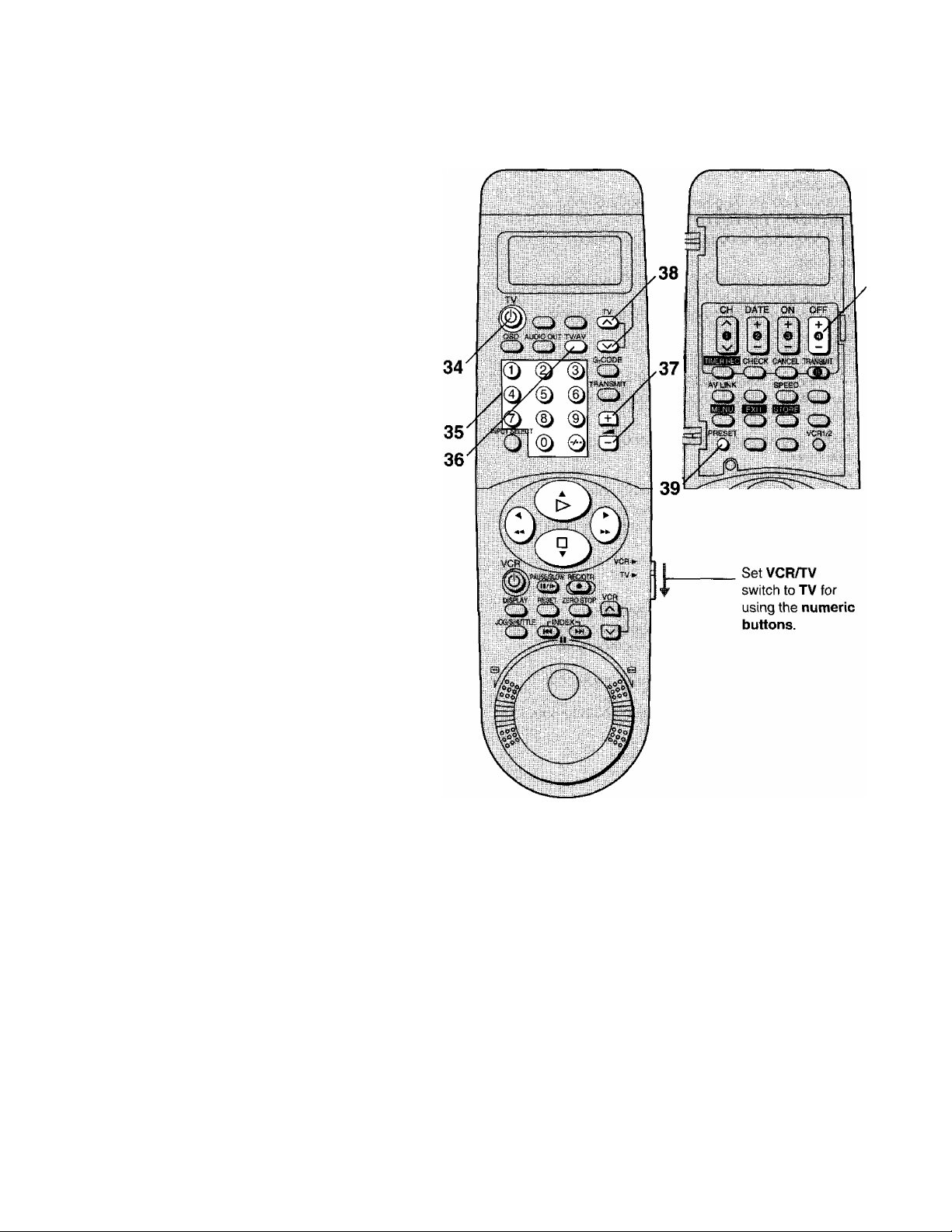
TV OPERATION
Refer to page 25.
34 POWER (TV)
To switch the TV from on to standby mode or vice
versa, in standby mode, the TV is stili connected to
the mains.
•With some TV models, it may only be possible to
switch the TV to standby mode using this button. In
this case, use TV/AV or \/ /s (TV) to switch the TV
on.
35 Numeric Buttons
Selects programme positions (1 -99) of the TV.
Ensure that VCR/TV switch is set to TV.
36 TV/AV
To seiect the TV input,
37 ^
Adjusts the volume of the TV.
38 V ^ (TV)
To select the required programme position (TV
station) of the TV.
39 PRESET
To set the remote controller for operation of the TV.
40 OFF
Sets the remote controller for operation of the TV.
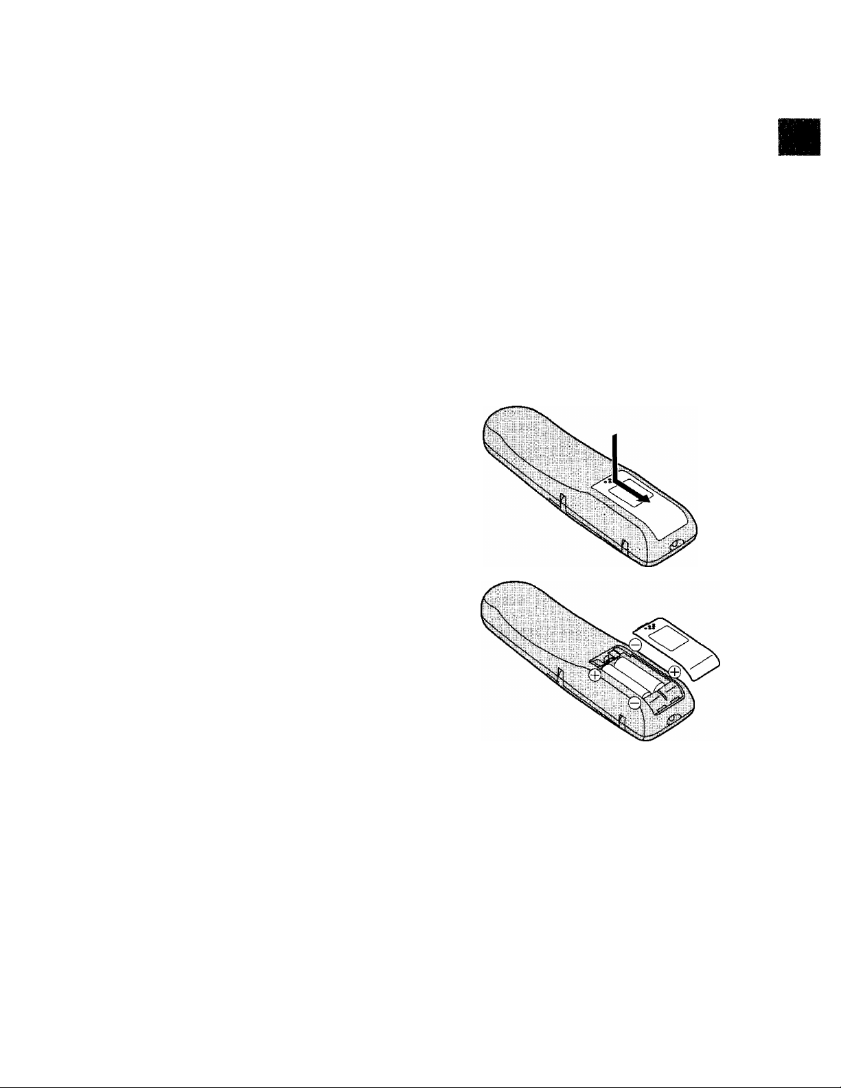
Power Source for the Remote Controller
The remote controller is powered by 2 “AA”, “UM3” or “R6”
size batteries. The life of the batteries is about one year,
although this depends on the frequency of use.
Precautions for Battery Replacement
• Load the new batteries with their polarity (© and ©)
aligned correctly.
• Do not apply heat to the batteries, or an internal
short-circuit may occur.
• If you do not intend to use the remote controller for a
long period of time, remove the batteries and store them
in a cool and dry place.
• Remove spent batteries immediately and dispose of
them.
• Do not use an old and a new battery together, and never
use an alkaline battery with a manganese battery.
Installing the Batteries
.o
Q
c
c
o
CO
q)
11
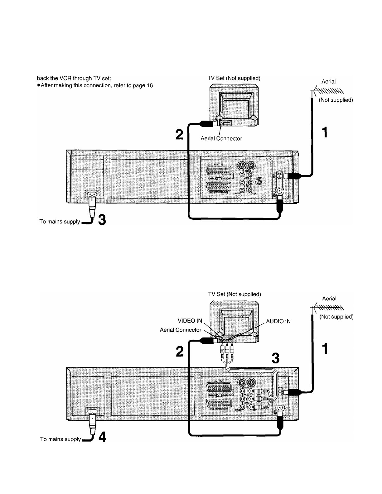
Connections
This tells you how to connect with an aerial, TV, etc.
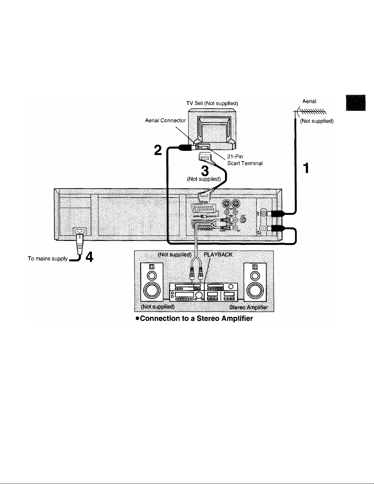
Basic Connections
The following connections are required to record and play
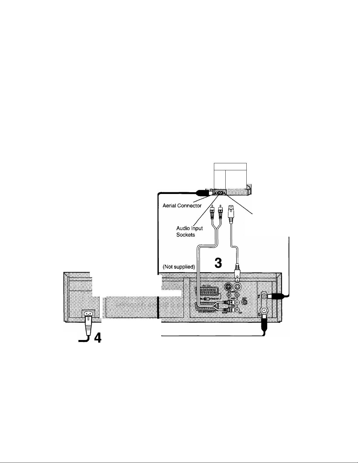
Connection to a TV using the Audio/Video Input Sockets
The following connections are required to record and play
back the VCR through TV set:
•After making this connection, refer to page 16.
12
Connection to a TV Set with 21 -Pin Scart Terminal
•After making this connection, refer to page 17.
Note:
Set the RF output channel of the VCR to “—” {RF OFF)
when the VCR is connected to the TV via the 21-pin scart
cable. See the bottom section on page 16.
§
.C
CD
CO
13
Connection to a TV Set with S-Video Socket
This VCR uses the S-VHS format that makes it possible to
obtain high resolution and high picture quality by using the
high-performance S-VHS video cassette tapes.
The conventionai video sockets of VCRs output (input) a
combination of the luminance signal (Y) and colour signal
(C) which are recorded on the video tape. The new S
(Separate)-Video Socket aliows separate transmission of
signals in order to obtain clearer pictures.
The connection with the S-Video Cabie can also be used
for playback of a tape that was recorded in the
conventional VHS system. The “S” in the “S-Video Socket”
stands for “SEPARATED Y/C” not for “S-VHS”.
TV Set (Not Supplied)
\
______
r
Aerial
/
' (Not Supplied)
To mains supply
—
—y
--------------------------------- g
— •—
---
---------------------------------------—»
S-Video Input
Socket
«:
S
«
1
14
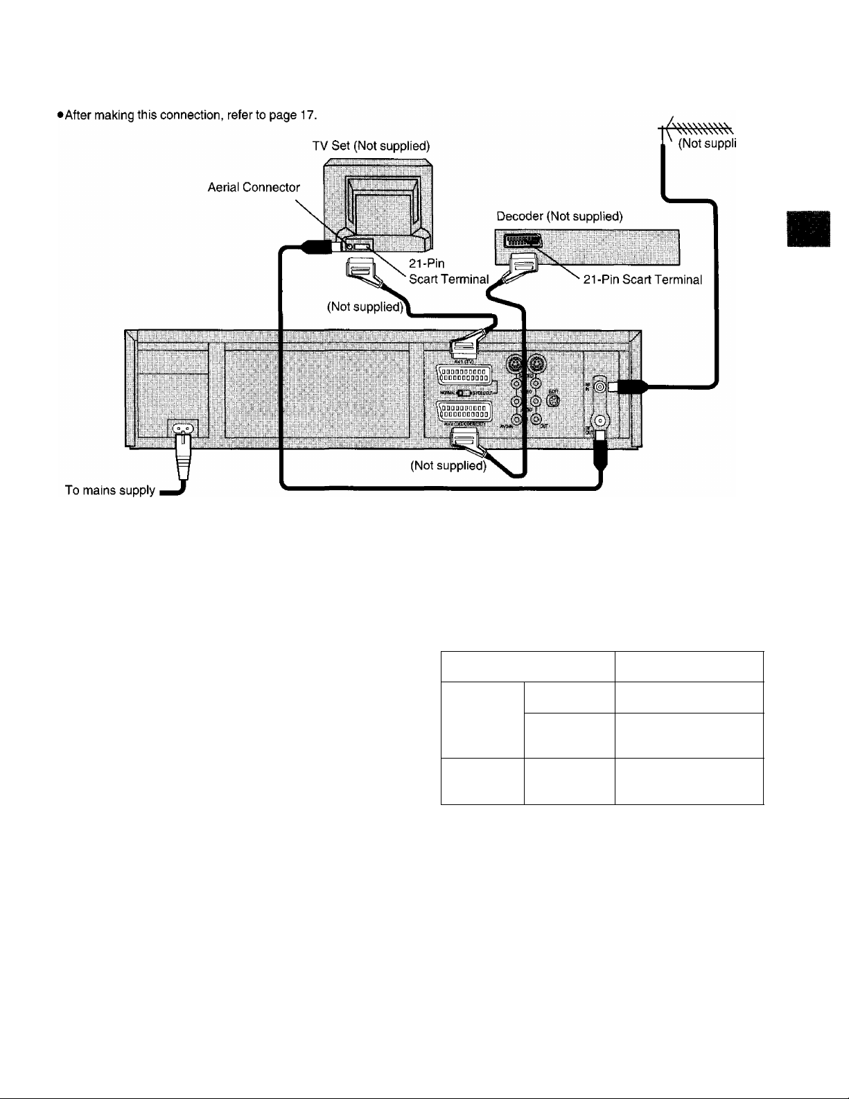
Connection to a Decoder
Aerial
O)
.C
£
Cl)
CO
Notes:
• If the TV set is provided with an RGB-compatible
connector, connect the 21 -pin AV cable from the VCR to
this connector. Use the fully-wired 21 -pin scart cable for
connecting the TV set and VCR and for connecting the
VCR and decoder.
•Set the RF output channel of the VCR to “—” (RF OFF)
when the VCR is connected to the TV via the 21-pin
scart cable. See the bottom section on page 16.
•When the decoder is connected to the AV2 socket, AV2
Connection must first be set to DECODER.
(See page 23.)
AV LINK
With this button the connected colour TV set can be
switched from TV mode to VCR mode (vice versa) when it
is connected by means of 21 -pin scart cable.
This makes a variety of functions possible, such as
simultaneous recording and viewing when a Pay TV
decoder or a satellite receiver has been connected.
VCR mode (VCR indicator lights):
To enjoy sound and pictures from the VCR.
•When MENU is pressed and the OSD (On Screen
Display) screen is displayed, the unit also automatically
switches to VCR mode.
However, if the unit is originally in TV mode, the VCR
indicator is not displayed.
•The unit also automatically switches to VCR mode when
playback is started. However, the unit cannot be
returned to TV mode during playback.
TV mode (VCR indicator goes off):
To watch another programme on the TV while recording
on the VCR.
•Select the programme to be watched using the TV set’s
tuner.
•The sound and pictures of a different channel are
received by the VCR.
VCR
VCR mode AV input selected
Power On
TV mode
Power Off
*When the VCR is set to the TV mode and the Pay TV
channel is selected, the signals will still be scrambled
even when Pay TV is selected by the TV set’s tuner. At a
time like this, either set the VCR to the VCR mode or
switch the TV set’s input signals to AV input.
—
Input from TV set’s
tuner*
Input from TV set’s
tuner
TVeet
15
 Loading...