

Panasonic NV-FJ623EG, NV-FJ623EGY, NV-FJ628EE Service Manual
Service Manual
ORDER NO. VRD0202004C2
Video Cassette Recorder
l NV-FJ623EG/NV-FJ623EGY/NV-FJ628EE
Z-MECHANISM
© 2002 Matsushita Electric Industrial Co., Ltd. All rights reserved. Unauthorized copying and distribution is a
violation of law.
1. INTRODUCTION
Note:
Procedures for Mechanism Chassis are separate volume from this service
The Model No. is indicated on the Schematic Diagram and Circuit Board
This service manual contains technical information which will allow service
personnel to understand and service this model.
If the circuit is changed or modified, this information will be followed by
supplementary service manual to be filed with original service manual.
1. Adjustment procedures, Disassembly Procedures and Assembly
manual./Please refer to the service manual for Z-Mechanism Chassis.
(Order No. VRD9802005C2)
2.
Diagrams as follows.
Model No. Indication Mark
NV-FJ623EG (EG)
NV-FJ623EGY
NV-FJ628EE (EE)
(EGY)
2.1.1 REPLACING IC7702/EEPROM
When the EEPROM: IC7702 is replaced, applicable model code, option code and electrical adjustment data will
not be available.
Therefore, enter and/or adjust the necessary data after replacing IC7702 by referring following procedure.
STEP1.REPLACE THE IC7702
1. Remove the C.B.A. with Mechanism unit by referring the Disassembly procedure.
2. Disconnect the AC plug and replace the IC7702.
STEP2.INPUT THE MODEL & OPTION CODE
1. Set up the applicable model code and option code by ordering the following table.
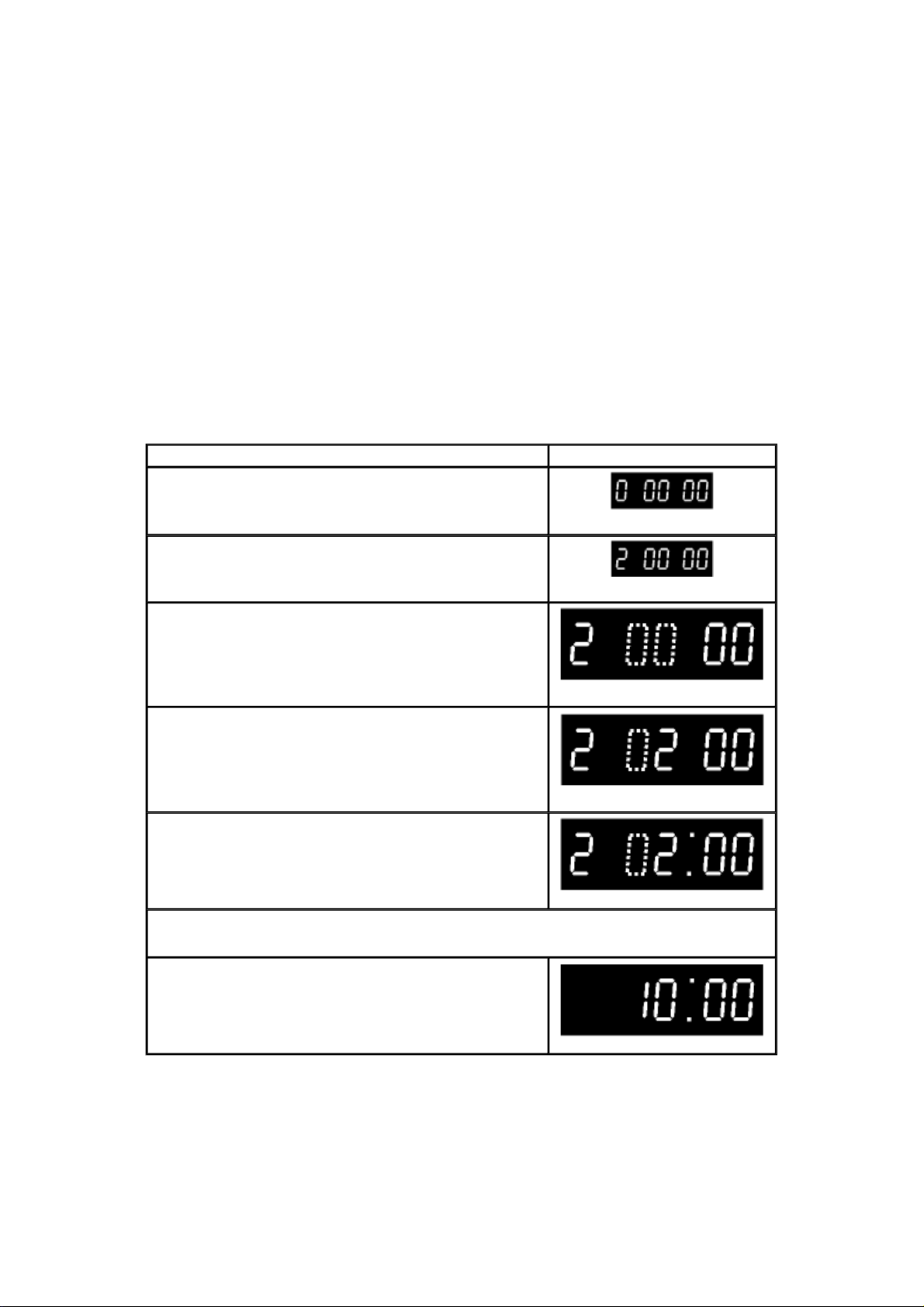
PROCEDURE F.I.P. DISPLAY
Turn on the Service Mode
1.Press the FF key and the EJECT key simultaneously for more than 3 seconds.
Activate the Service Mode 2
2.While keep placing FF key, press the EJECT key in twice.
Activate the Entering Mode.
3.Press the EJECT key for more than 3 seconds.
Set the Mode 2.
4.Press the CH UP key in twice.
Display the Setting Code.
5.Press the POWER Button to turn the power on.
(Colon starts flashing)
Enter the Model and Option Code.
6.Service Screen is displayed on the monitor.
7.Set the applicable Model and Option code by using REW, PLAY, STOP and FF keys on theRemote Controller. (See Fig.S1 & S2)
Exit from Service Mode.
8.Press the POWER Button to turn the power off.
9. Press FF and EJECT keys simultaneously in 6 times.
(Normal Indication)
Fig.S1 Service Secreen (sample)

NOTE:
Model No. Model
NV-FJ623EG/EGY 65
NV-FJ628EE 70
Option Code 1 Option Code 2 Option Code 3
Code
(41h)
(46h)
Fig. S2 Model Code & Option Code
125
(7Dh)
121
(79h)
196
(C4h)
196
(C4h)
6
(6h)
6
(6h)
Since all electrical adjustments data is still not available, perform the Electrical Adjustment continuously.
2.1.2 CYLINDER UNIT REPLACEMENT
1. CYLINDER UNIT REPLACEMENT
A. Remove the mechanism unit from MAIN C.B.A./Chassis by referring “SECTION 2. Disassembly
Procedure”.
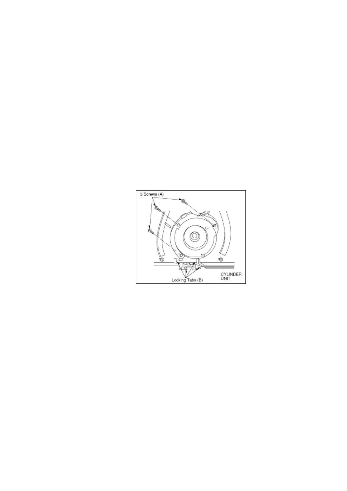
B. Remove the 3 screws (A) of the CYLINDER UNIT with a screw driver.
C. Unlock the 4 locking tabs (B) and disconnect the Cylinder flexible card from the FPC Holder.
D. Remove the CYLINDER UNIT.
CAUTION:
Handle the Cylinder flexible card with care. When it damaged, you should replace whole Cylinder
unit.
Fig. S3
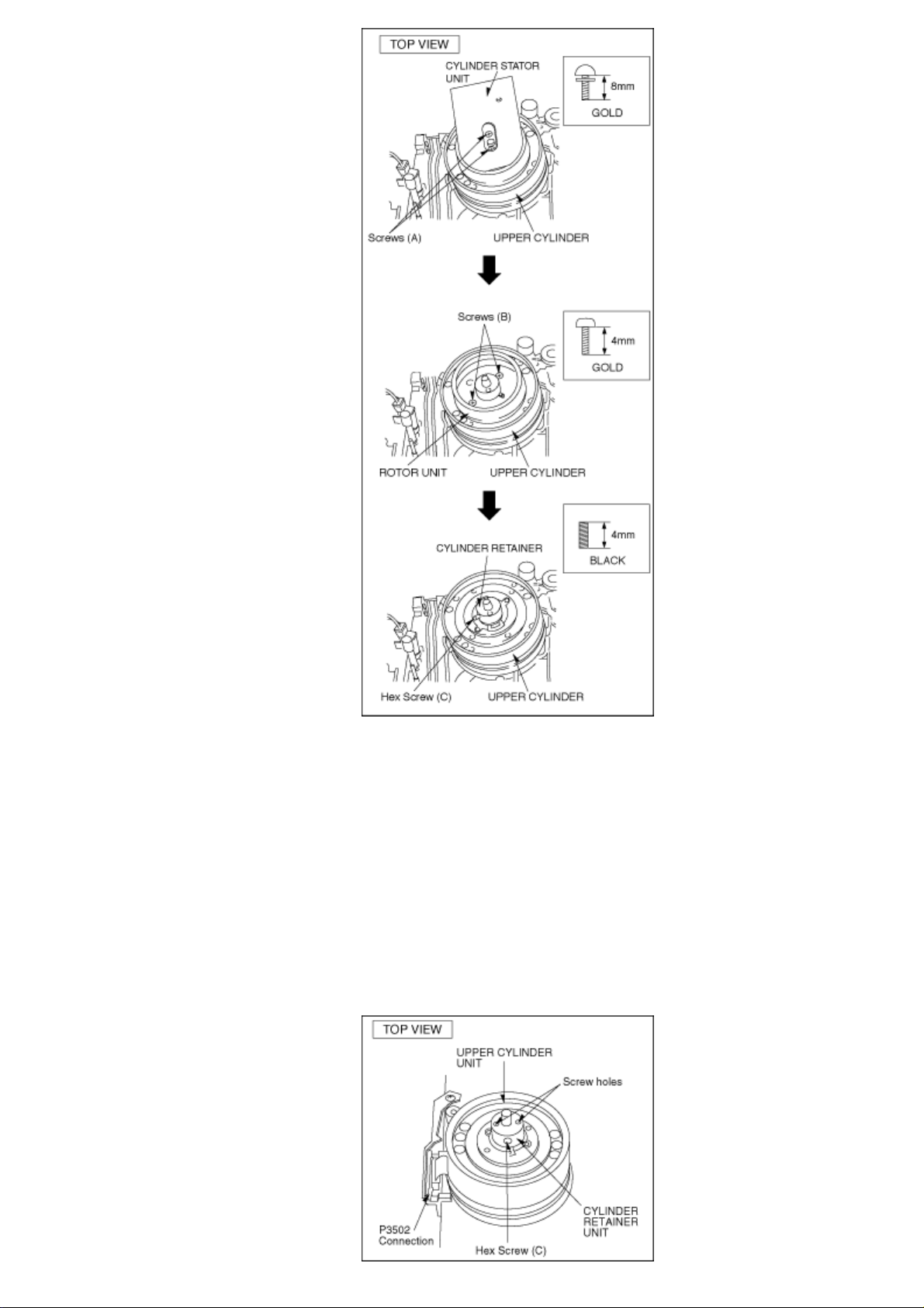
2. UPPER CYLINDER DISASSEMBLY
A. Remove 2 screws (A).
B. Remove the Cylinder Stator Unit.
C. Remove 2 screws (B).
D. Remove the Cylinder Rotor Unit.
E. Loose Hex screw (C) (1.5 mm) and remove the CYLINDER RETAINER.
F. Remove the Upper Cylinder.
Fig. S4
3. UPPER CYLINDER ASSEMBLY
When reassembling, perform the steps in the reverse order.
Notes:
A. Install the Cylinder Retainer so that the 2 holes on top of the Cylinder Retainer are at right angles
with the P3502 Connection.
B. Tighten the Hex screw (C) (1.5 mm) while pressing down on top of the Cylinder Retainer.
Fig. S5
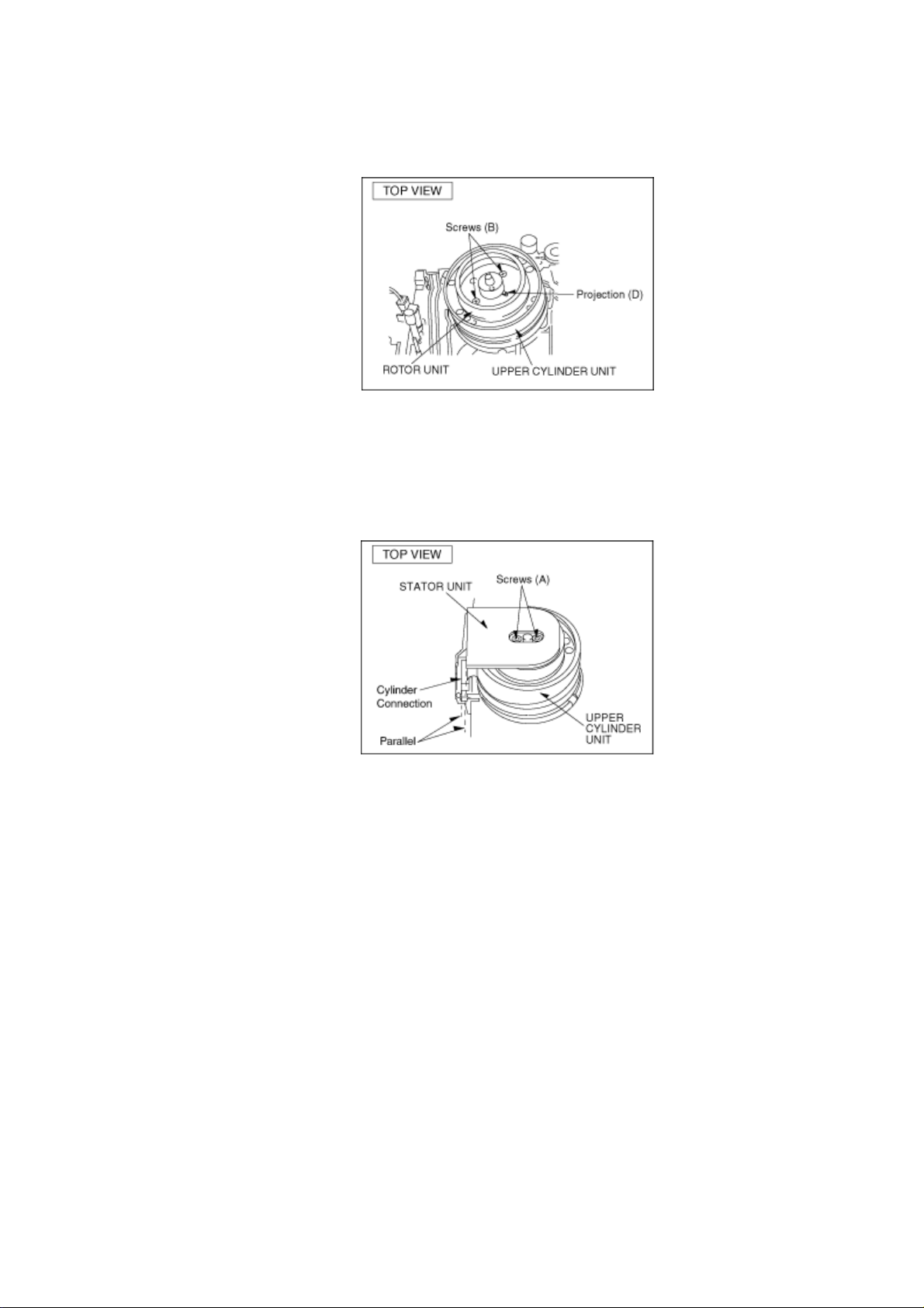
C. Install the Cylinder Rotor Unit so that the inner hole of the Cylinder Rotor Unit fits to the small
projection (D) on top of the Upper Cylinder.
D. Tighten 2 screws (B).
Fig. S6
E. install the Cylinder Stator Unit.
F. Tighten 2 screws (A).
Fig. S7
G. Confirm the PG SHIFTER ADJUSTMENT with the alignment tape (PAL: VFJ8125H3F) and adjust
it if necessary.
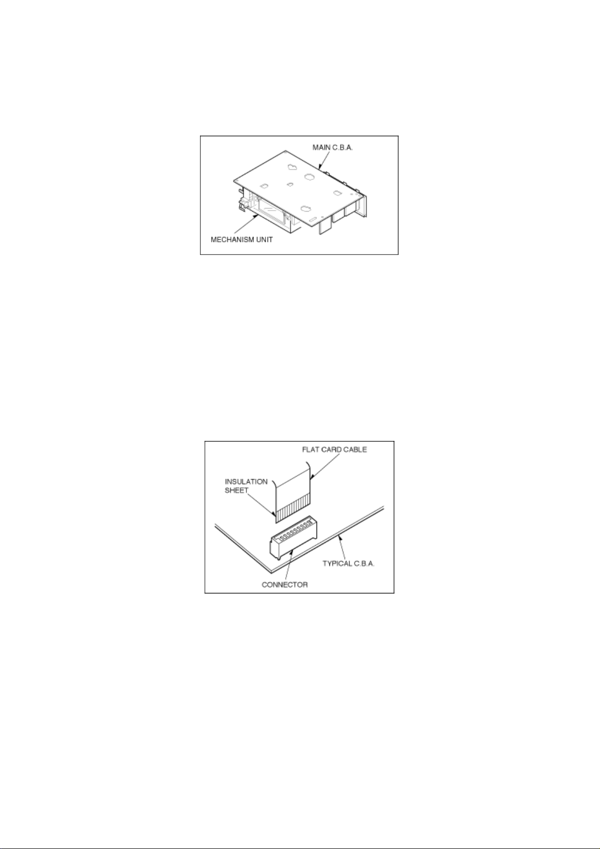
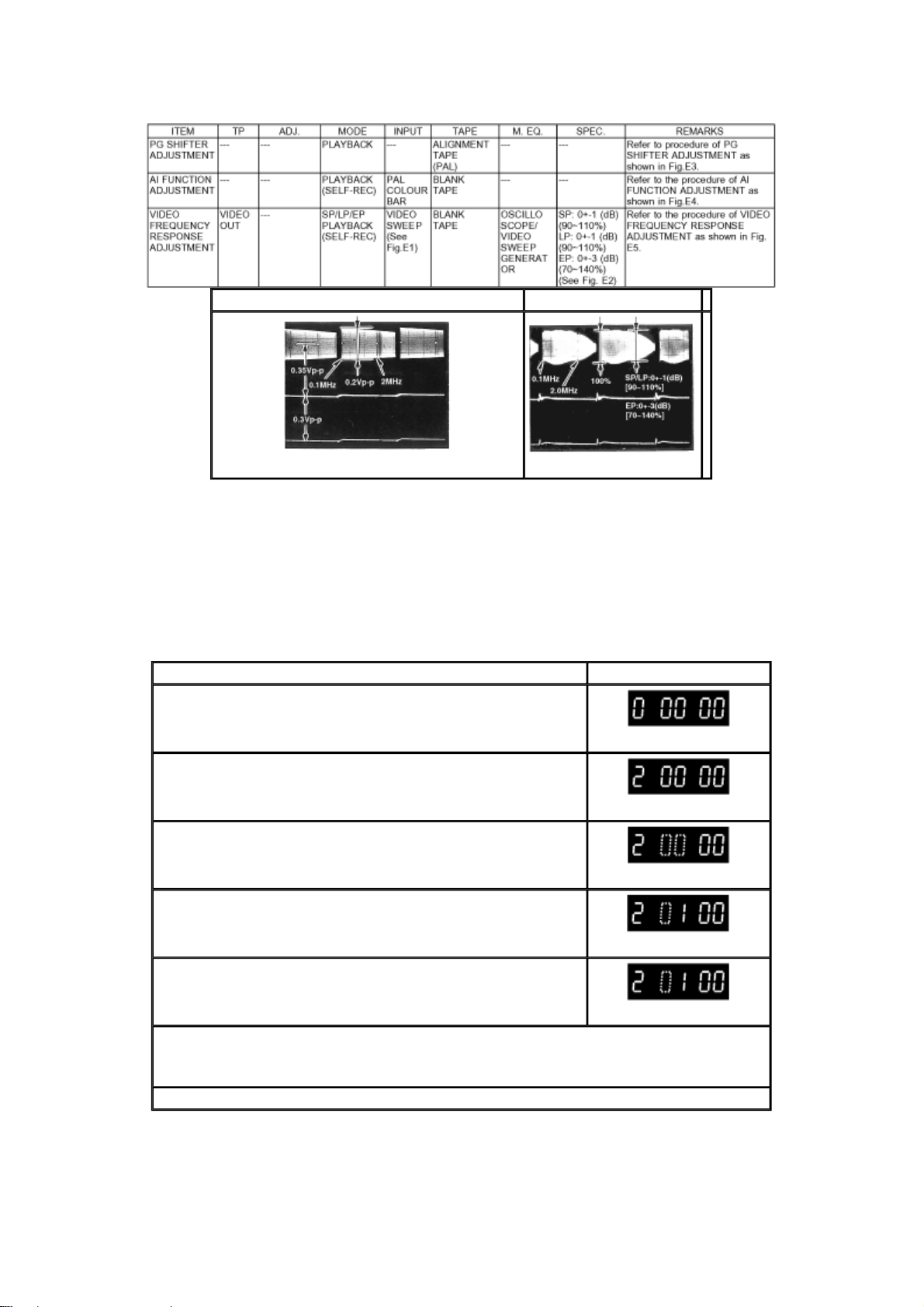
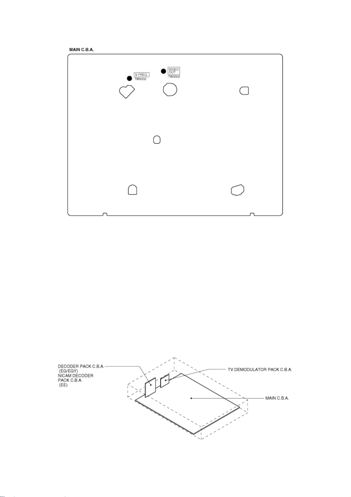
2.1.3 CHECKING OF MAIN C.B.A.
When servicing the MAIN C.B.A., take out the MAIN C.B.A. and mechanism from the frame and turn over.
Fig. S8
2.1.4 FLAT CARD CABLE INSTALLATION
When installing the Flat Card Cable on the connector, install the Flat Card Cable with the cable contacts facing
the connector contacts.
Fig. S9
2.2 REMOVAL OF CASSETTE TAPE
There are 2 ways to remove a cassette tape.
1. Service Information Display Operation
A. Press the FF and EJECT keys simultaneously for 3 seconds and set the Service Mode 7.
B. Press STOP key in order to rotate the Loading Motor for unloading operation. (Pay an attention of
tape slack)
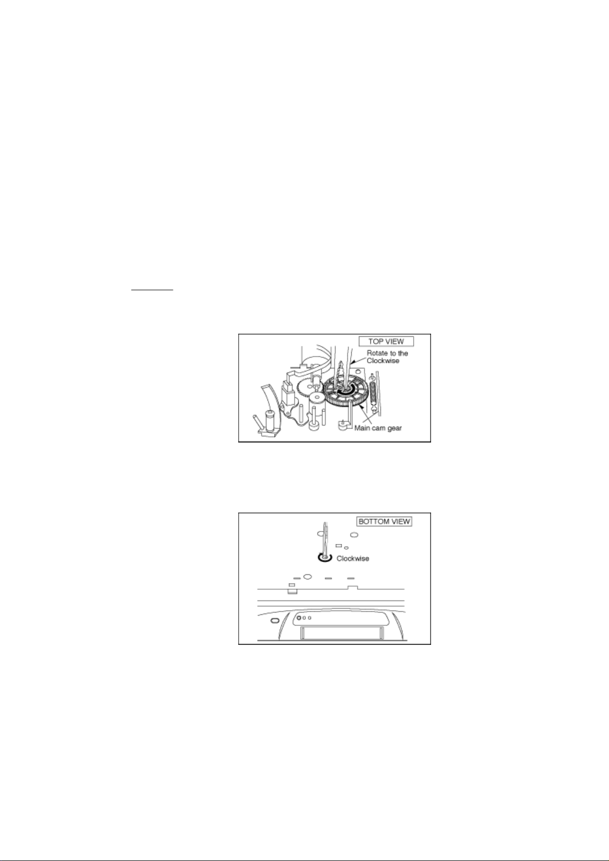
2. Manual Operation
A. Disconnect the AC Mains Lead and remove the Top Panel.
B. Rotate the Main Cam Gear clockwise until the Loading Posts move to fully unloaded position as
shown in Fig. S10 . (Tape is remaining)
Fig. S10
C. Rotate the Capstan Motor clockwise from the bottom side to take up the tape.
Fig. S11
D. Rotate the Main Cam Gear clockwise until the cassette tape is ejected.
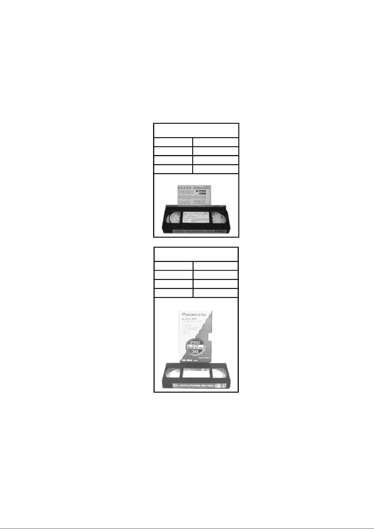
2.3 INTRODUCTION OF VIDEO HEAD CLEANING CASSETTE/
(POLISHING TYPE)
1. We are pleased to introduce Panasonic Video Head Cleaning Cassette, VFK0923FT [for service purposes]
and VFK0923FSE [ for end users] for all VHS/SVHS VCP and VCR.
2. These cleaning cassettes are exclusive removing the hard and sticky clogging on video heads.
3. These improve the efficiency of video head cleaning service and shortening cleaning time for end users.
VFK0923FT
(For Service usage)
Type of Cassette Full VHS Cassette
Cleaning Time 10 Seconds/Time
Tape Length 20 m
Usability in a Path 180 Times
Note:
VFK0823FSE
(For end users)
Type of Cassette Full VHS Cassette
Cleaning Time 10 Seconds/Time
Tape Length 3.34 m
Usability in a Path 30 Times
The tape material itself is the same in both types.
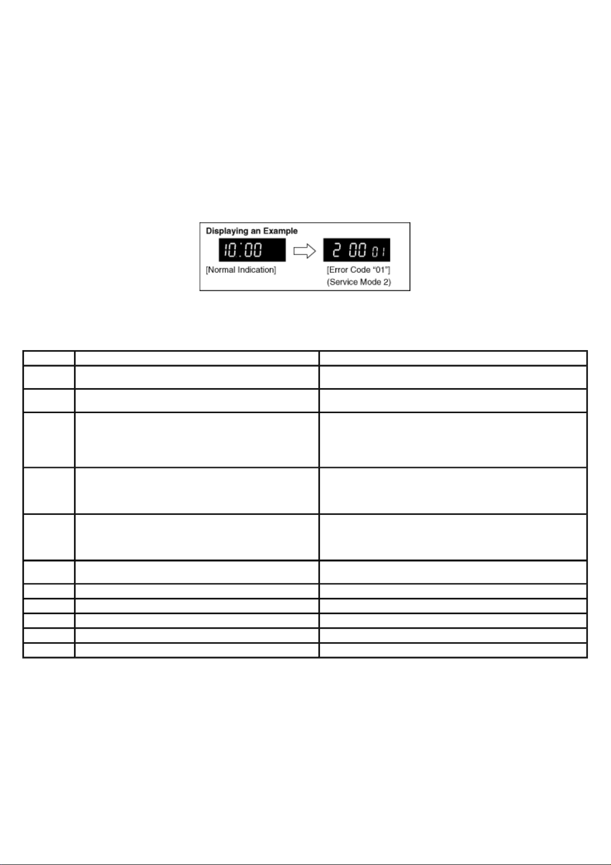
2.4 SELF-DIAGNOSIS RESULT DISPLAY
The "SELF-DIAGNOSIS RESULT DISPLAY & MEMORY function is built in this VTR.
It means that when the VCR detects undesirable condition, it can be displayed a “Error code (Two numbers from
the right)” with Service Mode 2.
Since the "Error code" is stored in the EEPROM, it can be displayed although after disconnected the AC leads. It
can be displayed with Service Mode 2.
(If a second error had been detected, only the most recent error is displayed. )
For more details, refer to the Service Manual for Z-Mechanism Chassis Order number VRD9802005C2.
Fig. T1 Self-Test indication Display
INDICATION
01 After cylinder lock is detected, the cylinder does not start rotating again
even after tape unloading.
02 Cassette tape is not wound up during the tape unloading except EJECT
mode.
03 Mechanism locks during mode transition except EJECT mode. 1. Check the loading motor drive circuit.
04 Mechanism locks during tape unloading. 1. Check the loading motor drive circuit.
06 Mechanism locks after tape unloading in EJECT mode. 1. Check the loading motor drive circuit.
07 During recording mode, recording signal is less than the normal condition. Protection of the over-current flowing in transistor which produces the power
08 Recording circuit works except recording mode. Check the recording circuit.
16 Cylinder lock detection. Check the cylinder unit and the cylinder motor drive circuit.
17 Supply reel mechanism lock detection Check the supply reel mechanism and the supply reel circuit.
18 Take-up reel mechanism lock detection Check the Take-up reel mechanism and the Take-up reel circuit.
2* PG shifter automatic adjustment error. Check the servo/system control circuit and the cylinder unit.
CAUSE REMEDY/CHECK
Check the cylinder motor drive circuit.
Check the capstan motor drive circuit.
2. Check the mechanism phase alignment.
3. Check the mode switch.
2. Check the mechanism phase alignment.
2. Check the mechanism phase alignment for cassette holder unit.
supply for recording mode.
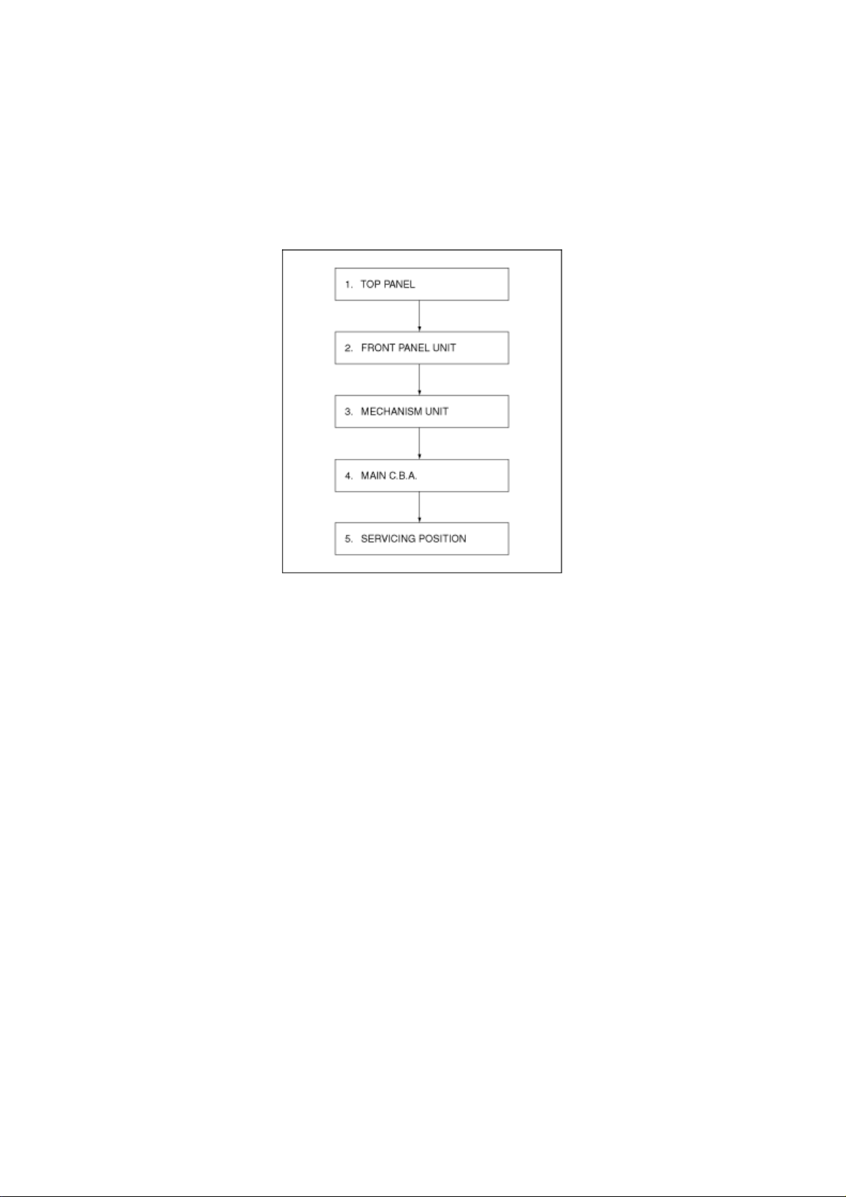
3.1.1 DISASSEMBLY FLOW CHART
This flow chart indicates disassembly steps of the cabinet parts and the circuit boards in order to find the
necessary items for servicing.
When reassembling, perform the steps in the reverse order.
Fig. D1
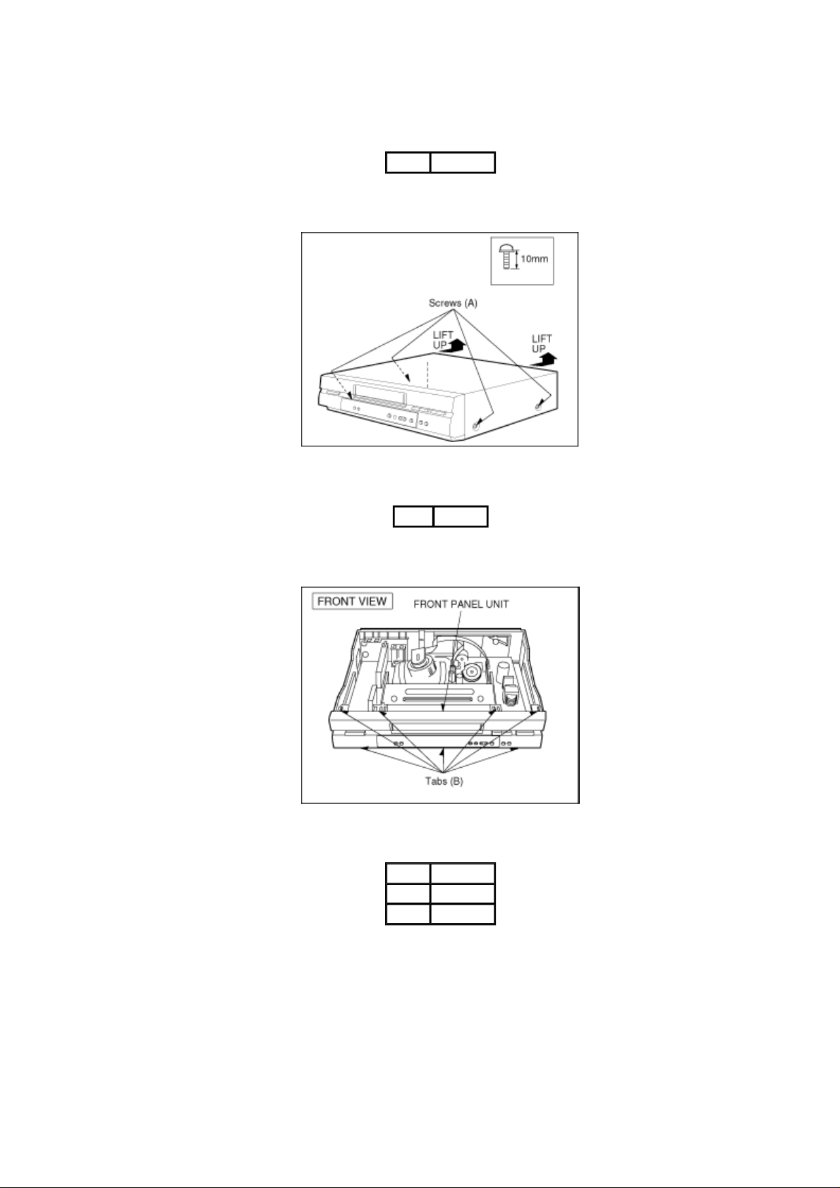
3.1.2 DETAIL OF DISASSEMBLY METHOD
1. REMOVAL OF THE TOP PANEL
Remove 4 Screws (A)
Fig.D2
2. REMOVAL OF THE FRONT PANEL UNIT
3. REMOVAL OF THE MECHANISM UNIT
Unlock 7 Tabs (B)
Fig. D3
Remove Screw (C)
Remove 3 Screws (D)
Remove 2 Screws (E)
Note:
A. Keep pressing 2 stoppers on Cassette Holder Plate and Press Cassette Holder Plate to the rear.
B. Remove the Mechanism Unit after bend the Cylinder Shield in the direction of the arrow.
Fig. D4
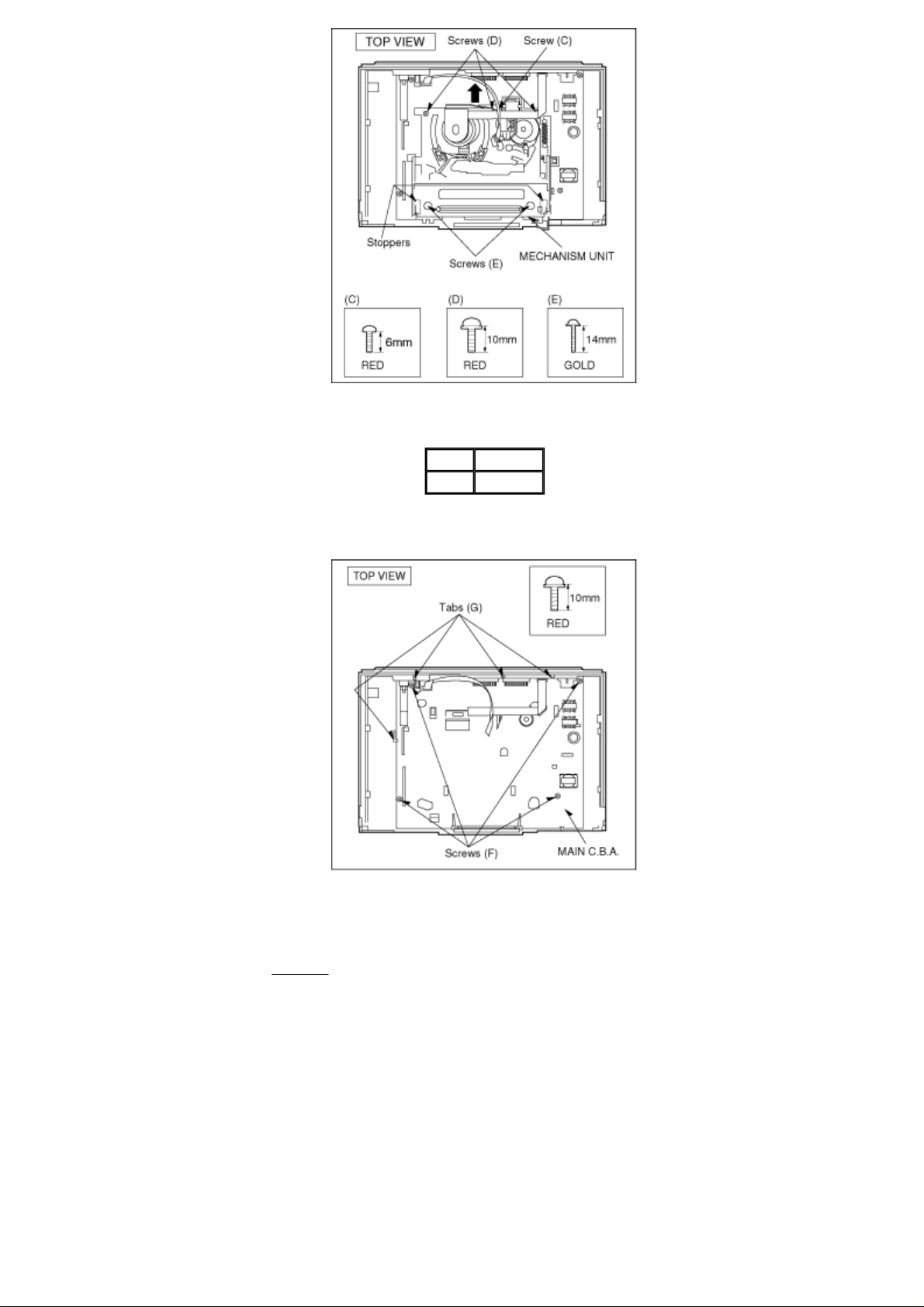
4. REMOVAL OF THE MAIN C.B.A.
Fig. D6
Remove 4 Screws (F)
Unlock 4 Tabs (G)
Fig. D5
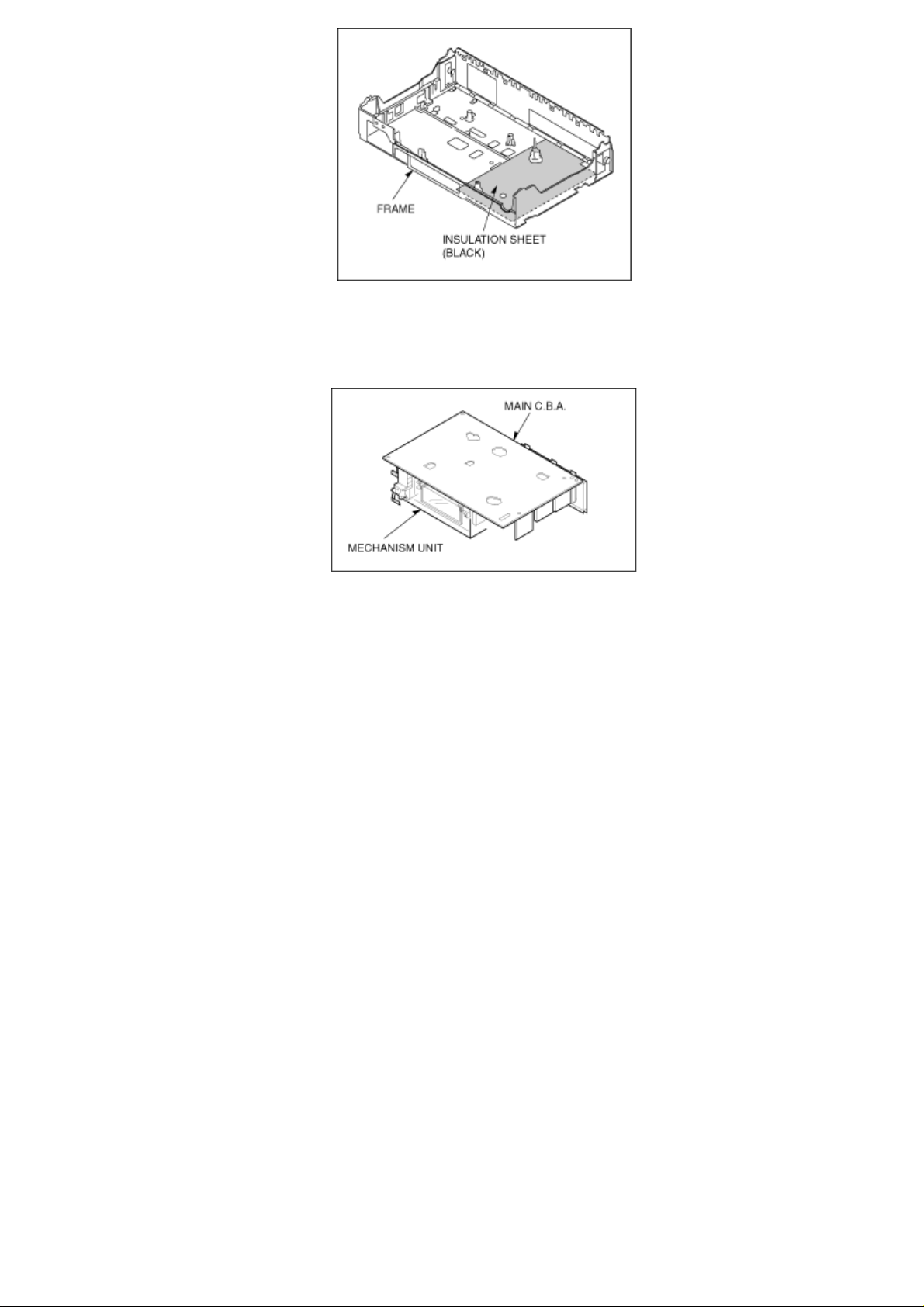
NOTE:
Before mounting the MAIN C.B.A. onto the frame, be sure to confirm that the insulation sheet is mounted
on the frame as shown in Fig. D6 .
5. SERVICING POSITION
Fig. D7
3.2 MECHANICAL ADJUSTMENT PROCEDURES
Refer to the Service Manual for Z-Mechanism Chassis./(Order No. VRD9802005C2)

3.3.1 TEST EQUIPMENT
(Set to signal input terminal number)
The following equipments are required for Electrical Adjustments.
1. Dual-Trace Oscilloscope
¡
Voltage Range: 0.005-5V/div
¡
Frequency Range: DC-35MHz
¡
Probes: 10:1 / 1:1
2. Frequency Counter
¡ Frequency Range: 0-10MHz
¡
Probes: 1:1
3. Universal Counter
4. Digital Volt Meter (D.V.M.)
5. Video Sweep Generator
6. Sinewave Generator
7. Video Pattern Generator
8. Monitor TV
9. DC Power Supply
10. VHS Blank Tape
11. VHS Alignment Tape
¡
Parts No.: VFJ8125H3F(PAL)
3.3.2 VCR SETTING
When no indication in the procedure, set each selector as follows:
1. TAPE SPEED: SP
2. CHANNEL: AV1
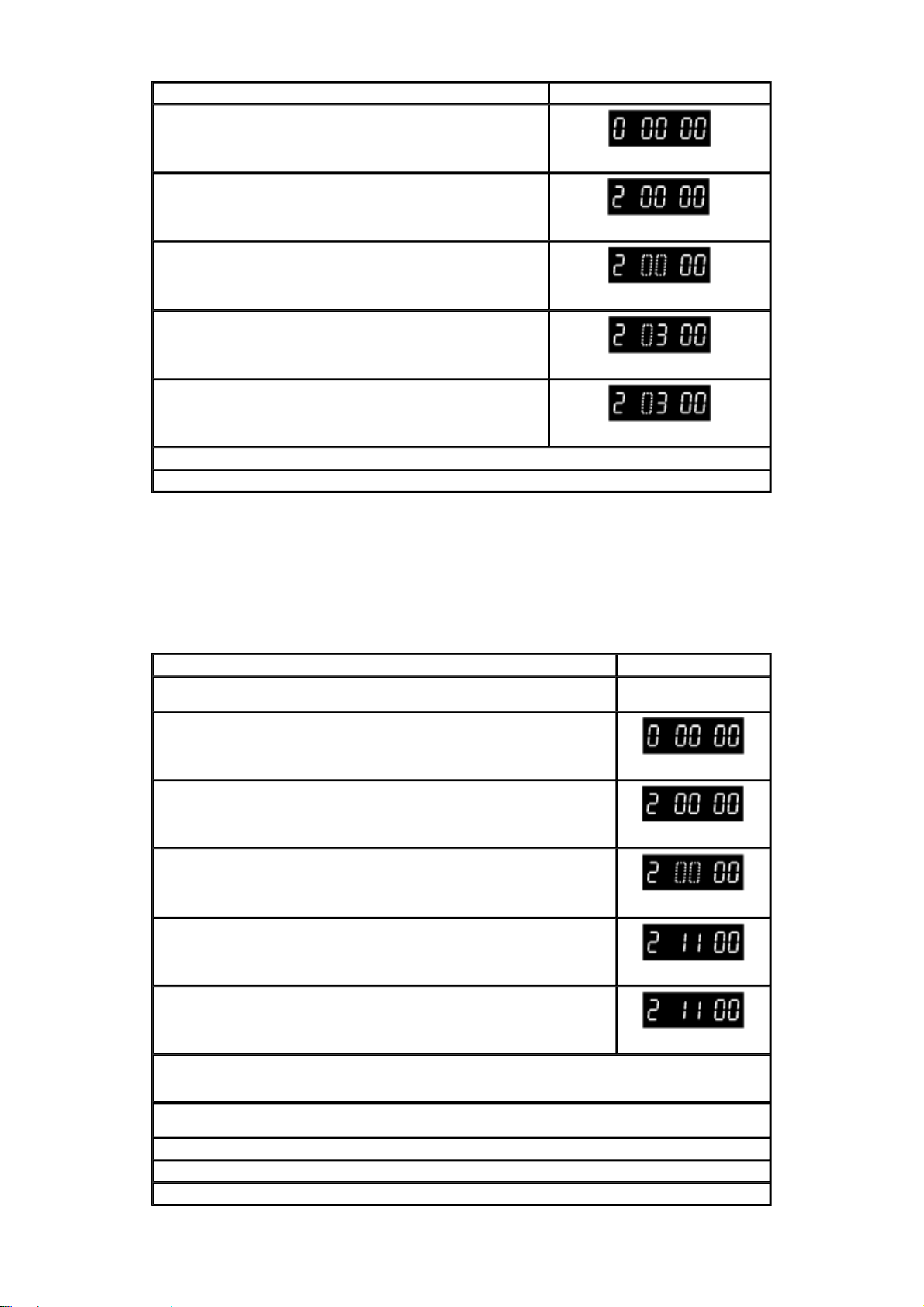
3.3.3 ADJUSTMENTS
Fig.E1 Fig.E2
CONDITION: BURST SIGNAL OFF / 75 ohm TERMINATED
3.3.4 PG SHIFTER ADJUSTMENT/(AUTOMATIC)
PROCEDURES FIP DISPLAY
Press the FF and EJECT Keys
simultaneously for 3 seconds.
Press the FF and EJECT Keys
simultaneously twice.
Press the EJECT key for 3 seconds.
Press the CH UP key once.
Insert the Alignment cassette tape. (PAL:VFJ8125H3F)
When the sequence of the automatical adjustment has been terminated, the following action has been made.
*SUCCEED: The cassette tape is ejected.
*ERROR : The "F2"is displayed on the FIP.
(Check the Servo/Syscon circuit and Cylinder unit.)
Release the Service mode by pressing the EJECT and FF keys simultaneously in 6 times until the FIP becomes normal indication.
Fig. E3
3.3.5 AI FUNCTION ADJUSTMENT (AUTOMATIC)
PROCEDURES FIP DISPLAY
Press the FF and EJECT Keys
simultaneously for 3 seconds.
Press the FF and EJECT Keys
simultaneously twice.
Press the EJECT key for 3 seconds.
Press the CH UP key in 3 times.
Insert the blank cassette tape.
(The adjustment is automatically started.)
When the sequence of the automatical adjustment has been terminated successfully, the VCR goes to STOP mode.
Release the Service mode by pressing the EJECT and FF keys simultaneously in 6 times until the FIP becomes normal indication.
Fig. E4
3.3.6 VIDEO FREQUENCY RESPONSE ADJUSTMENT
PROCEDURES FIP DISPLAY
Input the Video sweep signal.
(See Fig.E1)
Press the FF and EJECT Keys
simultaneously for 3 seconds.
Press the FF and EJECT Keys
simultaneously twice.
Press the EJECT key for 3 seconds.
Press the CH UP and/or CH DOWN key until "11" is displayed on FIP.
Insert the Self-recorded tape and playback it. (SP/LP/EP mode)
Connect the Oscilloscope to:
*CH1....Video Out (TW3002).
*CH2....V.FREQ.(TW6002)
Press the "4" key on the remote controller.
(Confirm that TW6002 becomes high(5V)).
Adjust the Frequency response by pressing the "2"(increase) and/or "8"(decrease) key on the Remote Controller. (See Fig.E2)
Store the Adjusted value by pressing the "5" key on the Remote Controller.
Release the Service mode by pressing the EJECT and FF keys simultaneously in 6 times until the FIP becomes normal indication.
Fig. E5
3.3.7 LOCATION OF TEST POINTS& CONTROLS
3.3.8 CIRCUIT BOARD LAYOUT

443NT [L]
A. COMP
A. COMPO
A. D.P [L]
A. D/L [L]
A. DEF [S]
A. DEF [S] [L]
A. DUB P [L]
A. DUB [H]
A. ERASE
A. H. SW
A. HEAD [R]
A. HEAD [W]
A. IN [L]
A. IN [R]
A. MUT [H]
A. MUTE [H]
A. OUT [L]
A. OUT [R]
A. RF OUT
A/VS/S. DATA
AC ONLINE
AC. O/EE. H
AFC S C
AFC [S]
AFC. DEF
ARFC OUT
ART. V
ART. V. MM
ART. V/H/N
AT. V/H/N
ATSW/TEST/NOR/SE
AUDIO IN [L]
AUDIO IN [R]
AUDIO OUT [L]
AUDIO OUT [R]
AUDIO SELECT [H]
AUDIO. L
AUDIO. R
AV CNT
AV CTL
AV CTL/S. CLK
AV. C.M.
AVCNT/METER. R
AVSW/METER. L
B MODE. H
B.G.P
BACKUP 5V
BAND. U.E.
BANDVL. D
BI/MI [L]
4.43 NTSC
AUDIO COMPONENT SIGNAL
AUDIO COMPONENT SIGNAL
AUDIO DUBBING PAUSE
AUDIO DUBBING PAUSE L
AUDIO DEFEAT
AUDIO DEFEAT
AUDIO DUBBING PAUSE
AUDIO DUBBING H
AUDIO ERASE
AUDIO HEAD SWITCHING PULSE
AUDIO HEAD (REC)
AUDIO HEAD (PLAY)
AUDIO INPUT (L)
AUDIO INPUT (R)
AUDIO MUTE
AUDIO MUTE H
AUDIO OUTPUT (L)
AUDIO OUTPUT (R)
AUDIO RF SIGNAL OUTPUT
AV SW/SERIAL DATA
AC ONLINE
AC ONLINE/EE
AFC S CURVE
AFC S CURVE
AFC DEFEAT
AUDIO RF SIGNAL OUTPUT
ARTIFICIAL VERTICAL SYNC SIGNAL
ARTIFICIAL VERTICAL SYNC
SIGNAL MONO MULTI
ARTIFICIAL VERTICAL SYNC
SIGNAL
ARTIFICIAL VERTICAL SYNC SIGNAL
TEST/NORMAL/SERVICE
AUDIO INPUT (L)
AUDIO INPUT (R)
AUDIO OUTPUT (L)
AUDIO OUTPUT (R)
AUDIO SELECT
AUDIO (L)
AUDIO (R)
AV CONTROL
AV CONTROL
AV CONTROL/SERIAL CLOCK
AV CONTROL MODE
AV CONTROL/LEVEL METER (R)
AV SW/LEVEL METER (L)
B MODE
BURST GATE PULSE
BACK UP 5V
BAND U
BAND VL
BILINGUAL/MIX
L
L
L
H
H
H/NORMAL
H
H
L
BIL
BIL [L]
BIL. [H]
BIL/M1 [L]
BS CLOCK
BS DATA
BS LCH IN
BS MIX [H]
BS MON [H]
BS MONI [H]
BS RCH IN
BS VIDEO
BS VIDEO/BS1
BS [H]
BS. LEVEL
BS. M [H]
BS/VTR [H]
BUS CLK
BUS LSN
BUS TLK
BUZZER
CAP EC
CAP M GND
CAP. ET
CAP. FG1
CAP. FG2
CAS. SW
CCN
CCP
CHM
CHP
CINEM [L]
CINEMA [L]
CINEMA/MIX
CKL
CKS
CL
CLK
CLK (C.G)
CLOCK. IN
CLP
COL/B/W/NOR
COLOR [H]
CONV
CS
CTL GND
CTL HEAD [
CTL HEAD [
CTL [
CTL [
CUE BIAS
CURRENT LIM
CYL ET
+
−
]
+
]
−
BILINGUAL
BILINGUAL
BILINGUAL H
BILINGUAL L
BS CLOCK
BS DATA
BS L CHANNEL INPUT
BS MIX
BS MONITOR H
BS MONITOR H
BS R CHANNEL INPUT
BS VIDEO SIGNAL
BS VIDEO SIGNAL
BS
H
BS LEVEL
BS MONITOR
BS/VTR H
BUS CLOCK
BUS LISTEN
BUS TALK
BUZZER
CAPSTAN TORQUE CONTROL
CAPSTAN MOTOR GND
CAPSTAN TORQUE CONTROL
CAPSTAN FG1 PULSE
CAPSTAN FG2 PULSE
CASSETTE SW
PLAYBACK CONTROL SIGNAL (−)
PLAYBACK CONTROL SIGNAL (
CONTROL SIGNAL (+)
CONTROL SIGNAL (
CINEMA
CINEMA L
CINEMA/MIX
RATCH LOCK
SHIFT LOCK
CLOCK
CLOCK
CLOCK
CLOCK INPUT
CLAMP
COLOUR/BLACK & WHITE/NORMAL
COLOUR H
CONVERTOR
CHIP SELECT
CONTROL GND
]
]
CONTROL HEAD (
CONTROL HEAD (
CONTROL HEAD (
CONTROL HEAD (
CUE BIAS
CURRENT LIMMITER
CYLINDER TORQUE CONTROL
H
L
L
H
+
)
−
)
+
)
−
)
+
)
−
)

CYL GND
D.F.M. REC [H]
D. FM REC [L]
D. GND
D. REC [H]
D4/S. LED
D4/STILLED
DAC [CLK]
DAC/FSCS
DAREC [H]
DATA
DECODER [L]
DECODER [R]
DEW
DEW SNS
DFMRE [H]
E. REC 5V
EC
ECR
EDT TRIG [L]
EDIT [H]
EE [H]
EE [H]/INS [M]
EE. VV. TR
EJECT. PO
EJECT/VDET
ENV. SEL
ENVE. OUT
ENVE. SEL
ENV SELECT
EP [H]
EP/LP [H]
EP/LP/SP
EP/SS [H]
EPROMCS
EX. REC 5V
FF/REW [L]
FG1 IN
FG2 IN
FILTER ADJUSTMENT
FLY ERASE [H]
FLY ON [H]
FLY. E [H]
FM MUT [H]
FM MUTE [H]
FM OUT [L]
FM OUT [R]
FM PACK OUT [L]
FM PACK OUT [R]
FM/BS SEL [L]
FM/BS SEL [R]
FS. CLK
FUL. E [H]
FULL. E [H]
CYLINDER GND
DELAIED FM RECORDING
DELAIED FM RECORDING L
DIGITAL GND
DELAYED RECORDING
D4/STILL LED
D4/STILL LED
TUNER DAC (CLOCK)
TUNER DAC/FS CHIP SELECT
DELAYED AUDIO RECORDING
DATA
DECODER (L)
DECODER (R)
DEW
DEW SENSOR
DELAYED FM AUDIO RECORDING
EXCEPT RECORDING 5V
ERROR TORQUE CONTROL
ERROR TORQUE CONTROL
REFERENCE VOLTAGE
EDIT TRIGGER
EDIT H
EE H
EE H/INSERT M
EE/VV/TRICK PLAY
EJECT POSITION
EJECT/REVERSE SLOW LOCK
ENVELOPE SELECT
ENVELOPE OUTPUT
ENVELOPE SELECT
ENVELOPE SELECT
LP
H
LP H
LP/SP
LP/SLOW/STILL/STOP
EPROM CHIP SELECT
EXCEPT RECORDING 5V
FIRST FORWARD/REWIND
FG1 PULSE INPUT
FG2 PULSE INPUT
FILTER ADJUSTMENT
FLYING ERASE HEAD ON
FLYING ERASE HEAD ON H
FLYING ERASE HEAD ON H
FM AUDIO MUTE H
FM AUDIO MUTE H
FM OUTPUT (L)
FM OUTPUT (R)
FM PACK OUTPUT (L)
FM PACK OUTPUT (R)
FM/BS SELECT (L)
FM/BS SELECT (R)
FS CLOCK
FULL ERASE HEAD ON
FULL ERASE HEAD ON H
L
H
H
H
H
H
L
H
H
FULL. E. 12V
GND [A]
GND [TU]
GND/N. SW. 12V
H. SYNC
H. AMP. SW
H. P <R>
H. P <L>
H. P GND
H. P OUT [L]
H. P OUT [R]
H. SW
HEAD PHONE [L]
HEAD PHONE [R]
HEAD SW
HEATER [
HEATER [
HSS
HTR [
HTR [
I RFE
ICL
IF
IN SELA1
IN SELA2
IN SELA3
INS L/R [L]
INS. [H]
INSEL A1
INSEL A2
INSERT
INSERT [H]
IO CS
JOG1
JOG S3 LED/FOWRD
JOG/F. LED
JSB [H]
JST. CLCK
JST. CLK
JST. CLOCK
L. OUT
L. CH [H]
L. CH [L]
LED (MAIN)
LED (STEREO)
LED (SUB)
LED CKL
LED CKS
LED DATA
LINE IN 1 [L]
LINE IN 1 [R]
LINE IN 2 [L]
LINE IN 2 [R]
LINE IN V
LINE IN [L]
+
]
−
]
+
]
−
]
FULL ERASE 12V
GND (ANALOG)
GND (TUNER)
GND/NON SW 12V
HORIZONTAL SYNC
HEAD AMP SW PULSE
HEAD PHONE (R)
HEAD PHONE (L)
HEAD PHONE GND
HEAD PHONE OUTPUT (L)
HEAD PHONE OUTPUT (R)
HEAD SW PULSE
HEAD PHONE (L)
HEAD PHONE (R)
HEAD SW
H
H
H
+
)
−
)
+
)
−
)
L
HEATER (
HEATER (
HORIZONTAL SYNC SIGNAL
HEATER (
HEATER (
REFERENCE CURRENT
CONTROL AGC CIRCUIT
INTERMEDIATE FREQUENCY
INPUT SELECT A1 POSITION
INPUT SELECT A2 POSITION
INPUT SELECT A3 POSITION
INSERT Lch/Rch
INSERT H
INPUT SELECT A1 POSITION
INPUT SELECT A2 POSITION
INSERT
INSERT
INPUT/OUTPUT CHIP SELECT
JOG1
JOG LED/FORWARD LED
JOG LED/FORWARD LED
JSB
JUST CLOCK
JUST CLOCK
JUST CLOCK
Lch OUTPUT
Lch
Lch L
LED (MAIN)
LED (STEREO)
LED (SUB)
LED SERIAL CLOCK
LED SERIAL CLOCK
LED SERIAL DATA
LINE INPUT 1 (L)
LINE INPUT 1 (R)
LINE INPUT 2 (L)
LINE INPUT 2 (R)
LINE INPUT VIDEO
LINE INPUT (L)

LINE IN [R]
LINE OUT [L]
LINE OUT [R]
LP [H]
LPTRI [L]
Lch/A. DUB
M GND
M REG
MAIN OUT
MAIN [L]
MAIN/MONO
MAX IN
MES [H]
MESE [H]
MESE [L]
METER 5V
METER [L]
METER [R]
METER. L/AVS
METER. R/AVC
MI/BI [L]
MIC GND
MIC IN
MIC IN [L]
MIC IN [R]
MIC [H]
MIX [H]
MIX [H]/CINEMA [L]
MIX/CINE
MIX/CINEMA [L]
MN. H/M. L
MN. H/MAI. L
MN2/MES. L
MODE SEL
MODE SW
MODE. S. IN
MODE. S. OUT
MONO [H]
MONO [H]/MAIN [L]
MONO2 [L]
MONO2/MESE [FM(L)]
MOTOR GND
MUTE
N. A. REC [L]
N. SW 12V
N. SW. 5. DET
NICAM
NICAM [L]
NOL [H]
NOR/SOFT [H]
NORMAL [H]
NR BIAS
NTSC [L]
OCH
OUT
LINE INPUT (R)
LINE OUTPUT (L)
LINE OUTPUT (R)
LP
H
LP TRICK PLAY L
Lch/AUDIO DUBBING
MOTOR GND
MOTOR REGULATOR
MAIN OUTPUT
MAIN
L
MAIN/MONAURAL
MAXIMAM INPUT
MESECAM
MESECAM H
MESECAM L
LEVEL METER 5V
LEVEL METER (L)
LEVEL METER (R)
LEVEL METER (L)
LEVEL METER (R)
MIX
MIC GND
MIC INPUT
MIC INPUT (L)
MIC INPUT (R)
MIC
MIX H
MIX H/CINEMA SOUND L
MIX H/CINEMA SOUND L
MIX H/CINEMA SOUND L
MONAURAL H/MAIN L
MONAURAL H/MAIN L
MONAURAL 2/MESECAM L
AUDIO MODE SELECT
AUDIO MODE SW
AUDIO MODE SELECT INPUT
AUDIO MODE SELECT OUTPUT
MONAURAL
MONAURAL H/MAIN L
MONAURAL 2
MONAURAL 2/MESECAM (FM
MOTOR GND
MUTE
NORMAL AUDIO RECORDING
NON SW 12V
NON SW 5V DETECT
NICAM
NICAM
PAL H/4.43 NTSC M/3.58 NTSC
NORMAL/SOFT TAPE PLAY H
NORMAL H
NR BIAS
NTSC
CONTROL AGC CIRCUIT
OUTPUT
H
H/BILIGUAL
H
H
L
L
P-OFF [H]
P-OFF [L]
P. FAIL
P. OFF [H]
P. OFF [L]
PAL [H]
PAL [L]/NTSC [H]
PB ADJ OUT
PB OUT
PB. H
PFG
PHOTSN +B
PICT. CNT
PLAY LED/RVS LED
PLAY. PO
PLAY/R. LED
PLY/DEW
POWER OFF [L]
PREROLL [H]
PWRFAIL
R. CH [H]
R. CH [L]
R. ST
R/S/F
RCH [H]
REC 12V
REC CHROMA
REC H
REC IN
REC OUT [L]
REC START
REC VR [C]
REC VR [L]
REC VR [R]
REC Y
REC [H]
REC. C
REC. Y
REC/EE CTL
REEL-T
REEL-S
L)
REGULATOR FILTER
RESET
REV M F/R
REV M V1
REV M V2
REV MOTOR F/R
L
REV MOTOR V1
REV MOTOR V2
REV MOTOR [
REV MOTOR [
REV. M. GND
RF. CHROMA
POWER OFF
POWER OFF L
POWER FAILURE DETECT
POWER OFF
POWER OFF L
PAL H
PAL L/NTSC H
PLAYBACK ADJUST OUTPUT
PLAYBACK OUTPUT
PLAYBACK
PG/FG
PHOTO SENSOR +B
PICTURE CONTROL
PLAY LED/REVERSE LED
PLAY POSITION
PLAY LED/REVERSE LED
PLAY/DEW
POWER OFF L
PREROLL H
POWER FAILURE DETECT
Rch
H
Rch L
RESET
REVERSE H/STOP M/FORWARD
Rch H
RECORDING 12V
RECORDING CHROMINANCE SIGNAL
RECORDING H
RECORDING INPUT
RECORDING OUTPUT
RECORDING START
RECORDING VOLUME (COMMON)
RECORDING VOLUME (L)
RECORDING VOLUME (R)
RECORDING LUMINANCE SIGNAL
RECORDING H
RECORDING CHROMINANCE SIGNAL
RECORDING LUMINANCE SIGNAL
RECORDING/EE CONTROL
REEL PULSE (TAKE-UP)
REEL PULSE (SUPPLY)
REGULATOR FILTER
RESET
REVIEW MOTOR
FORWARD/REVERSE
REVIEW MOTOR V1
REVIEW MOTOR V2
REVIEW MOTOR
FORWARD/REVERSE
REVIEW MOTOR V1
REVIEW MOTOR V2
+
]
−
]
REVIEW MOTOR (
REVIEW MOTOR (
REVIEW MOTOR GND
RF CHROMINANCE SIGNAL
H
H
H
H
L
L
+
)
+
)

RF OUT
RF Y
RF. Y. IN
RF. Y. OUT
ROTAR. SW
ROTARY
RST
RST [L]
Rch/INST
S IN
S OUT
S-PHOTO
S-RL. PLS
S. CLK
S. CLK/AV
S. DATA
S. DATA/A
S. PHOTO
S. TAB [L]
S/P/N
SC IN
SC OUT
SCK SELECT
SEL OUT [L]
SEL OUT [R]
SHUTTLE 1
SIF
SLMUT [H]
SLNID [
SLNID [
SLW TR. MM
SLW TR. REF
SNS. GND
SOFT [H]
SOFT [H]/NORMAL
SOLENOID ON [L]
SP [H]
SP/L/SLP
SSS [L]
STEREO LED
STEREO [H]
STEREO [L]
STOP. PO
STOP/5V
STOP1/TAPE SEL
STOP1/PAL:ST
STOP2. PO
STOP2/S-TAB
STREO [H]
SUB BIAS
SUB. SW
SVHS CAS [L]
SW. 5. DET
SYNC [L]
+
]
−
]
RF OUTPUT
RF LUMINANCE SIGNAL
RF LUMINANCE SIGNAL INPUT
RF LUMINANCE SIGNAL OUTPUT
ROTARY SW
ROTARY SW
RESET
RESET
Rch/INSERT
SERIAL DATA INPUT
SERIAL DATA OUTPUT
SUPPLY PHOTO TRANSISTOR
SUPPLY REEL PULSE
SERIAL CLOCK
SERIAL CLOCK/AV
SERIAL DATA
SERIAL DATA
SUPPLY PHOTO TRANSISTOR
SAFETY TAB SW ON
SECAM/PAL/NTSC
SERIAL CLOCK INPUT
SERIAL CLOCK OUTPUT
SERIAL CLOCK SELECT
SELECT OUTPUT (L)
SELECT OUTPUT (R)
SHUTTLE 1
SOUND INTERMEDIATE FREQUENCY
INPUT SELECT MUTE H
SOLENOID (+)
SOLENOID (
SLOW TRACKING MONO MULTI
SLOW TRACKING REFERENCE
VOLTAGE
SENSOR GND
SOFT TAPE PLAY
SOFT TAPE PLAY H/NORMAL H
SOLENOID ON L
SP H
SP/LP
SLOW/STILL/STOP
STEREO LED
STEREO
STEREO L
STOP POSITION
STOP POSITION/5V
STOP1 POSITION/TAPE SELECT
STOP1 POSITION/PAL
STOP 2 POSITION
STOP 2 POSITION/SAFETY TAB SW
STEREO H
SUB BIAS
SUB SW
S-VHS CASSETTE
SW 5V DETECT
SYNC
L
L
H
L
−
)
H
L
SYSCON 5V
SYSTEM
T-PHOTO
T-RL. PLS
T. BUSCLK
T. BUSLSN
T. BUSTLK
T. END [L]
T. PHOTO
TAPE END [L]
TAPE END [L]/CAM
TEST
TPZ
TRIC [L]
TRICK [L]
TRK. ENV
TU. AUDIO
TU. GND
TU. V. IN
TU. VIDEO
TUN NOR IN
TUN R
TUN. AUDIO IN
TUNER 12V
TUNER L
TUNER V IN
TUNER [L]
TUNER [N]
TUNER [R]
TUNER. 12
TUOFF [H]
TV. AUDIO
TV/VTR
TXTON [L]
U. REG45V
UNREG
UNREG19V
V. REF
V. EE [H]
V. EE [L]
VCO REF
VD. IN
VD. OUT
VIDEO EE [L]
VIDEO IN
VIDEO OUT
VM
VM DOWN [L]
VSS
VTR [H]
VTR. 12V
X IN
X OUT
SYSTEM CONTROL 5V
SYSTEM SW
TAKE-UP PHOTO TRANSISTOR
TAKE-UP REEL PULSE
TIMER BUS CLOCK
TIMER BUS LISTEN
TIMER BUS TALK
TAPE END
TAKE-UP PHOTO TRANSISTOR
TAPE END
TAPE END L/CAMERA PAUSE
TEST MODE
TRAPEZOIDAL WAVE CIRCUIT
TRIC PLAY
TRIC PLAY L
AUTO TRACKING ENVELOPE DETECT
TUNER AUDIO
TUNER GND
TUNER VIDEO SIGNAL INPUT
TUNER VIDEO
TUNER NORMAL INPUT
TUNER AUDIO (R)
TUNER AUDIO INPUT
TUNER 12V
TUNER AUDIO (L)
TUNER VIDEO SIGNAL INPUT
TUNER AUDIO (L)
TUNER AUDIO (NORMAL)
TUNER AUDIO (R)
TUNER 12V
TUNER OFF
TV AUDIO
TV/VTR
TEXT ON
UNREGULATOR 45V
UNREGULATOR
UNREGULATOR 19V
REFERENCE VOLTAGE
VIDEO EE
VIDEO EE L
REFERENCE OSCILLATER
VIDEO SIGNAL INPUT
VIDEO SIGNAL OUTPUT
VIDEO EE
VIDEO SIGNAL INPUT
VIDEO SIGNAL OUTPUT
MOTOR VOLTAGE
MOTOR VOLTAGE DOWN
VERTICAL SYNC SIGNAL
VTR
VTR 12V
OSCILLATOR INPUT
OSCILLATOR OUTPUT
L
L
L
H
L
H
L
L
H
 Loading...